


rraisley
-
Posts
80 -
Joined
-
Last visited
Content Type
Profiles
Forums
Gallery
Events
Posts posted by rraisley
-
-
You may have seen these advertised on eBay: small Stern- and Mid-Sections (maybe Fore- as well) ship sections in 1:128 scale (pretty much fit in your hand) and are basic structural sections without a lot of detail. They interest me, looking for a new but simple project to work on. I know they are made in China, and know the opinion here about knock-offs, but don't see that they are copies of any other model. On eBay they sell for about $80 or so each, and are definitely shipped from China. I think I've seen Chinese sites offer them direct at lower prices, but they use the same photos, so if they both come from China, I would expect them to be identical kits and not, again, knock-offs. But I don't know that.
I searched here and found nothing, but was wondering 1) If there are thoughts against these types of kits, assuming they are /not/ knock-offs, and 2) Has anyone seen any or had any experience with them?
I could post links and pics, but haven't (yet) in case these kits are considered "no-no's".
-
On 5/21/2021 at 7:27 AM, allanyed said:
Piet,
What drawing format did you use? I have never done 3D drawings but have drawings in three views in 2D. Would that work?
Thanks
Alan, I can send you STL files for the guns we worked on, and if you'd like a different gun, send me the 3 view drawings and I'll see if I can make it for you. You've been a lot of help to me. Of course, if you're interested in doing it yourself in 3D, that's fine too.
- mtaylor, allanyed and Keith Black
-
 3
3
-
3 hours ago, Keith Black said:
I don't know that more uses for wood is a good idea? Wish they were using plastic waste.
Nah. Plastic waste can be clear and doesn't have a wood grain. Not suitable for window replacements. Let's chop down another tree, instead. 🤪
- mtaylor, Keith Black and davyboy
-
3
-
-
-
-
-
I took the easy way out and used 1/16" wide auto striping tape. I tried some graphic tape first, but it didn't stick well enough. I painted my mast yellow first, and then applied a gloss spray coat, to which the tape will stick (it won't stick at all on dull paint}. I then sprayed the mast, including the tape, with Dull Coat, figuring/hoping it would help seal the edges of the tape and help adhere it in place.
I think it looks good and expect it will last as long as I will on my model.
- Keith Black, mtaylor and thibaultron
-
3
-
3 hours ago, allanyed said:
Rick, Peterson's book is based on one contemporary model of a specific ship/rate/era (36 gun frigate late 18th century) and will not always be accurate for Victory compared to other books. Petersson's sketches are good and pretty easy to follow if you are building a fifth rate from that time frame.
So I see. There are a few pages that are helpful, and at least they usually show where the lines terminate.
-
7 hours ago, Ian_Grant said:
f you are not familiar with rigging in general, I recommend you obtain "Rigging Period Ship Models" by Petersson. This great book has almost no text, just line by line diagrams of each rigging component, one or two per page. Here is a sample page:
I just purchased an electronic Kindle copy of Petersson's book. I have also promised myself it is the last book I will buy in attempting to build this model.
When lines shown by authorities' drawings are "bogus", and when line descriptions here, and in the books, require a Google search by me for every other word (and conflict with other "authorities"), I think a visual representation which I can use while looking at diagrams, and fitting them to my situation, is best for me.
Thanks to everyone for your responses.
-
On 4/1/2021 at 7:12 AM, ubjs said:
But I want to build the model in a simpler way, I just want something that looks ok for someone who is not a specialist in ship models. I am looking for tips on how I can simplify construction.
I can definitely appreciate what you're trying to do. The last ship model I completed was the Popular Mechanics Chebec, when I was 16. It took me a year (a lot of time when your friends are out dating), and 60 years and 10 moves later has gone the way of the trash. Even then, it was simplified, due to my limited tools and budget (never could afford all the cannon).
I got my Victory cross-section model over 30 years ago, and it's not done. I bought the Corel (?) Berlin in between, and was smart enough to realize I would never finish it. I've seen finished, imported models on eBay (an example is a Victory cross-section), that finished, costs less than I paid for my Victory kit (not counting hundreds of dollars of add-ons and tools). I hope my Victory, assuming I finish it, will surpass the imported finished model, and I have seen some imported models, and the craftsmanship is not very good. But sitting on a shelf in the store, or a mantel at home, it is just as impressive.
The more I see of the level of craftsmanship displayed here, the more I realize my result will be closer to the imported model than to what others do here. But I am enjoying it. And I'm spending time, even for this model, that NO ONE will ever appreciate that sees the finished product.
No matter the model, if you enjoy building it and are happy with the result, just do it. Your way. The way you want to, simplified, partly built or whatever. I know my model would never be admired by sophisticated modelers; but unless I post it here, they'll never get to see it. My friends think it looks good (not knowing it from a plastic, pre-painted kit), and it will look good to me. At least from a distance. And if it doesn't, I just back up a little further. 😉
-
8 minutes ago, DelF said:
If you really want to press ahead then the best source I know is The Anatomy of Nelson's Ships by Longridge which, despite the title, just covers (in great detail) his construction of a 1:48 scale model of Victory.
I have Longridge's book, and have removed the rigging diagrams for reference. They have yet another version of the above information (similar for Lifts, short Halyards, if indeed that is what they are stopping at the main topgallant yard. Again - added confusion.
34 minutes ago, Mark P said:I think that the best solution to your dilemma is to try and purchase copy of James Lees' book 'The Masting and Rigging of English Ships of War, 1625-1860.
The cheapest I see it is $75. I just bought Wolfram zu Mondfeld's Historic Ship Models, and it has lots of great detail, but doesn't really answer a lot of my questions. Also bought Longridge's book as noted above, McGowan's HMS Victory, McKay's Victory book, etc. and am not getting far. Additional, conflicting yet incomplete information is not really helping.
-
I'm trying to start on the rigging of my Corel Victory cross-section, and think the rigging described and shown in the kit is rather simplistic (despite the fact that I still can't figure it all out), and so I've looked at maybe a dozen sources, and in many ways, am more confused now. I want to plan the rigging ahead of time, attach the appropriate blocks and connections to the correct places, prior to running thread all over.
I'm starting with the simple topgallant yard, by far the simplest, and I'm already confused. I'm showing portions of two rigging diagrams in McKay's book, which seems a good start:
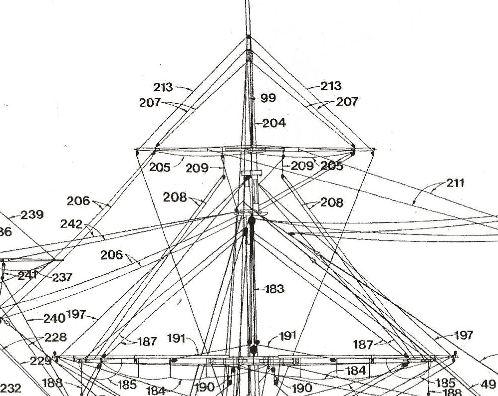
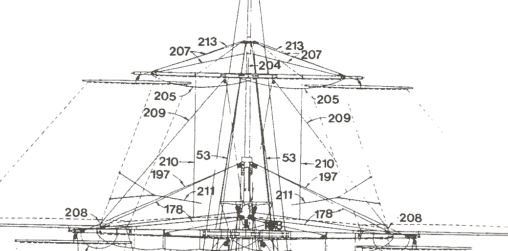
Using the table in the book, 207 are the Lifts for the Main Topgallant Yard, and consist of 2 blocks and 4 thimbles (I assume single, and that quantities are each side, with the quantities of this Lift being 2). I believe there will be a single block where the lift attaches to the yard, and another attached to the mast, where the rope will then continue downward. I guess there would be a thimble where the rope attaches to the mast, then another connecting the block to the yard and a third connecting the second block to the mast; I have no idea where a fourth thimble would be. As to the rope going down, would it go to all the way down to belaying pins at the base of the main mast, or would it be connected somewhere between? The 2.5" rope is listed as 65 fathoms long, so probably at the deck?
In the same area in this diagram are item 213, called the Halyard. It is 2" rope 84 fathoms in length with 6 blocks! Each side! Well, that short piece of rope between the mast and the yard is no 84 fathoms long, so it must continue down through a block attached to the end of the spar, back toward the Top. But where would it go from there? Where are the other 5 blocks? Why isn't this line shown on the second diagram above? (And it's not shown at all on the model's plans. And also not at all on some apparently excellent models I've seen.) While at first they seem to do the same thing (hold the topgallant yard in place), I realize that the Halyard line does not actually hold the yard, as it (probably) goes through a block on the yard.
You can see my level of confusion here: with only these first 2 lines, I don't know how they attach or where they go, and sources for this information varies. And confusion compounds as I go lower on the main mast, with so many more lines, whose function and connection are even more confusing. I hate to leave my cross-section model at only the hull and decks, or with a bare main mast, but I've spent over a month researching and buying books and am getting nowhere.
-
14 hours ago, Dr PR said:
I believe the tackle used to position the studding sail booms was temporary, and not left rigged permanently. It was taken aloft to rig the sails.
On smaller ships the booms may have been manhandled to push them out or haul them back in. When in position in/out the inboard end of the boom was lashed around the yard to hold it in place.
That makes a lot of sense. So the only thing I would model might be some eyes on the boom to connect the tackle. Actually, just one eye on the inner end would work.
-
2 hours ago, popeye2sea said:
To run out the booms, one end is hooked to the eye bolt in the inside end of the boom and the other end is hooked to the outer boom iron.
I haven't seen an eye bolt on any boom drawing. This drawing posted in another thread:

Does show a hold through the boom, close to inner end. McGowan appears to show a ring or cap on the inner end, to which a tackle is attached
Also, when the studdingsails are not in place, would the blocks mounted on the booms (again, shown in McGowan) which are used to hold the studdingsail yards and sails still be in place on the boom, just not used?
-
Back on the Studdingsail Booms, how are they moved in and out? While Studdingsail Yards and Sails are beyond the scope of my Victory cross-section (not having them), I'm sure there should be lines to extend and retract the Booms. But I don't see in McKay any attachments directly to the Booms. Page 190 of McGowan's HMS Victory book appears to show a tackle between the inner Stunsail support iron and the end of the boom, roped back to a block under the main spar, that would extend the boom, and ropes to the end of the boom which might go back to near the after mast, but I'm not sure and don't think I could model that on a cross-section, as there'd be nothing to attach it to.
-
As an retired engineer, I found this topic very interesting, especially the Age of Sail Ships available on Age of Sail Books at the Historic Naval Ships Association.
I also noticed with great interest Plate 5 of Chapter 1, which shows top masts and yards, as it definitely shows a practice I always felt was correct, but often not modeled, in the shape of the spars. I think typically, on models, spars are tapered linearly, that is having a constant taper beginning at the normally straight/parallel/octagonal center section, and tapering to a smaller diameter at the end. Thus, the proliferation of articles on tapering spars on a lathe, using two straight pieces of wood with sand paper on them, using a plane with guides or even using a chopstick-maker, all of which result in a straight and linear taper. But, from an engineering standpoint, a spar with a linear taper is weaker toward the center than ideal and/or thicker to the end, resulting in an inefficient use of wood and weight, especially so high up on a sailing ship.
I always felt that spars should be closer in shape to a really flat ellipse, tapering not at all near the center, and tapering much more toward the end. As the strength (section modulus) of any round component is proportional to the CUBE of the diameter rather than the diameter, so even if the bending moment were half the maximum the halfway out the spar, the required diameter would be closer to 80%, not 50%
Anyhow (sorry for being so wordy), the diagram quoted, from the above source, CLEARLY shows the taper in spars is NOT linear, but much more rounded, giving more strength toward the center than a linear taper would give it:
This is probably clearest on the largest Main or Lower Yard, by comparing its shape with the Studdingsail Boom above it on the left side. Also, the dimension of the diameter in fractions of the full diameter is given in many cases, and examining those values will show the varying taper along the length. (I used a spreadsheet, of course -- engineer!)
While I'm sure many modelers do make the spars "rounded" correctly this way, rather than with a linear taper, as I said above, with so many articles geared around producing a straight taper, it definitely gives the impression spars should have the linear taper, when in fact that is not correct (at least for many ships).
It's good to know that my "lazy" way of tapering spars, by using a belt sander and tapering by eye, resulting in a non-linear taper, in fact gives the more correct result! 🙂
- mtaylor, archnav and Jorge Diaz O
-
2
-
 1
1
-
-
I appreciate all your views. I'm a bit surprised that in the reviews of the medical style binocular loupes, no one has mentioned modeling, only dental and medical use.
I do have an Optivisor, and while it's a quality piece of equipment, I find it very cumbersome to use. You have to lift the hood up to see normally, and it very much limits view. The 3.0, 4.5 and 6.0 diopter reading glasses have been a great benefit in that way, easily seeing above or below the lenses, their extremely light weight, etc. But higher power means having your head extremely close to the work, which is what I'm thinking might benefit from the medical style I posted.
- Rik Thistle, Canute, thibaultron and 1 other
-
4
-
My 78 year old eyes are not what they used to be. And after cataract surgery, for which I paid extra for dual-focus (close and far) vision, turned out to be great for far, and crap for close, I've resorted to 3 pair of closeup reading glasses: 3.0, 4.5 and 6.0 diopter. They work pretty well, but require my object to be within as little as 6" from my glasses, not always optimum.
I was watching a TV operation tonight, and they used Surgical Binocular Loupes. A bit of research turned up these on Amazon. Not professional quality, but they give you 3.5 power at a distance of 420 mm (16" although a reviewer says it's closer to 12" which would be better for me, I think).
Has anyone used these or anything like them. My glasses work well, but I find myself hunched over my work in an uncomfortable position. Thought these might work well and preserve my posture and spine.
-
Similar to Jaager, I used a cut-off brad inserted into the bottom of the mast, and drilled a matching hole in a block at the keel. On my Victory cross-section, right from the beginning, I glued a piece of 1/16" walnut sheet across the top, from one side of the hull to the other, with a matching hole for the mast. In all stages of construction, from when I first started the hull until the net to last deck went on, I've simply slid the mast in place and used it as a guide to placing of support members and openings on all decks. By the time I got to the upper gun deck, the mast was held securely and accurately in place by the pin a the decks above it, so could remove the walnut piece.
-
19 hours ago, Don Case said:
Anyone use one of these? I was thinking it may be handy for fairing the inside of frames. They've always looked like an awkward thing to use to me. They are usually a couple hundred bucks but there is a Wen on Amazon.ca for $66. You usually get what you pay for but in this case the price is so different that you could get 3 for the price of a good one. I have read good reports on other Wen tools.

I bought the Wen 1/2" x 18" on Amazon (US) for $36.40 in January, and have found it very useful. From sanding off the extensions of grating assemblies, to tapering the pieces on the top of the Victory top, to squaring off portions of masts. At low speed, it works well enough, is easy to handle, and I even occasionally use it in my den, over the wastebasket, with my cat only 3 feet away, and it doesn't bother her. Definitely worth the money for me.
-
I have the same problem with my HMS Victory cross-section: Longridge's book shows parrals with rollers on the upper two locations, but mentions a truss on the lower mast. Yet the only drawing I've seen of a truss is simply a rope looped around it. It just seems funny to me we have a fancy holding mechanism on the upper two, and a length of rope on the lower one.
I'm really fairly stymied on the procedure with the main mast and spars; I know there should be blocks attached in some places, but it's hard to determine where. I'm afraid of getting ahead of myself, and finding it impossible to add what I need in the places they need to be. I've just been reading and searching everything I can, and looking in the four books I did buy to make this model. I can't justify more sources yet. Especially since no one but I will notice it. 😉
-
My only modeling tool for a l-o-n-g time was one of my dad's double edge razor blades. You know, the kind that cut the two fingers holding it with the less-sharp interior cuts. Later on, I learned to cover one edge with masking tape, meaning I could apply more pressure.
When I discovered single-edge blades, I thought I was in Heaven! I honestly don't remember any other tools in early modeling, as my dad's tools were mostly too large.
- bruce d, mtaylor, FlyingFish and 2 others
-
5

La Couronne by majq - Mantua - 1:98
in - Kit build logs for subjects built from 1501 - 1750
Posted
Just ran across this thread from a link on Pinterest, and so glad I did. Wonderful build! Just the kind of model I'd love to build, but probably couldn't. Great work!