Ian_Grant
-
Posts
2,153 -
Joined
-
Last visited
Content Type
Profiles
Forums
Gallery
Events
Everything posted by Ian_Grant
-
 Ah, now I understand. Thanks everyone! I had thought the post was connected to the big bar, which I now know is the traveller. Guess I didn't look hard enough. 😉
 -
Interesting photo, like nothing I've ever seen. Questions: Is that the steering gear? Does the big beam slide side to side through the bulwarks? Does it move twin rudders? Why a tackle on one side only? Questing minds seek to know.🤔
-
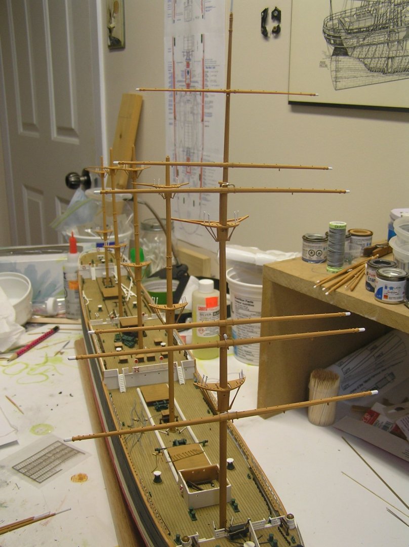
Not too realistic. I've procured a lot of 3/32" blocks for the lower yards. For the uppermost I will probably just use beads and live with it. I may have bitten off more than I can chew with the number of 3/32" blocks. Also, still wondering how to represent the sister blocks on the bulwarks for the lower yard braces. Simply gluing some blocks on sideways seems a bit fragile. Here she is with all yards crossed now, if not all straight. You can see why I'm reconsidering the foot ropes 🙄.

-
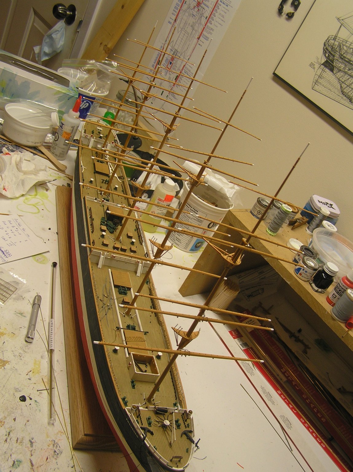
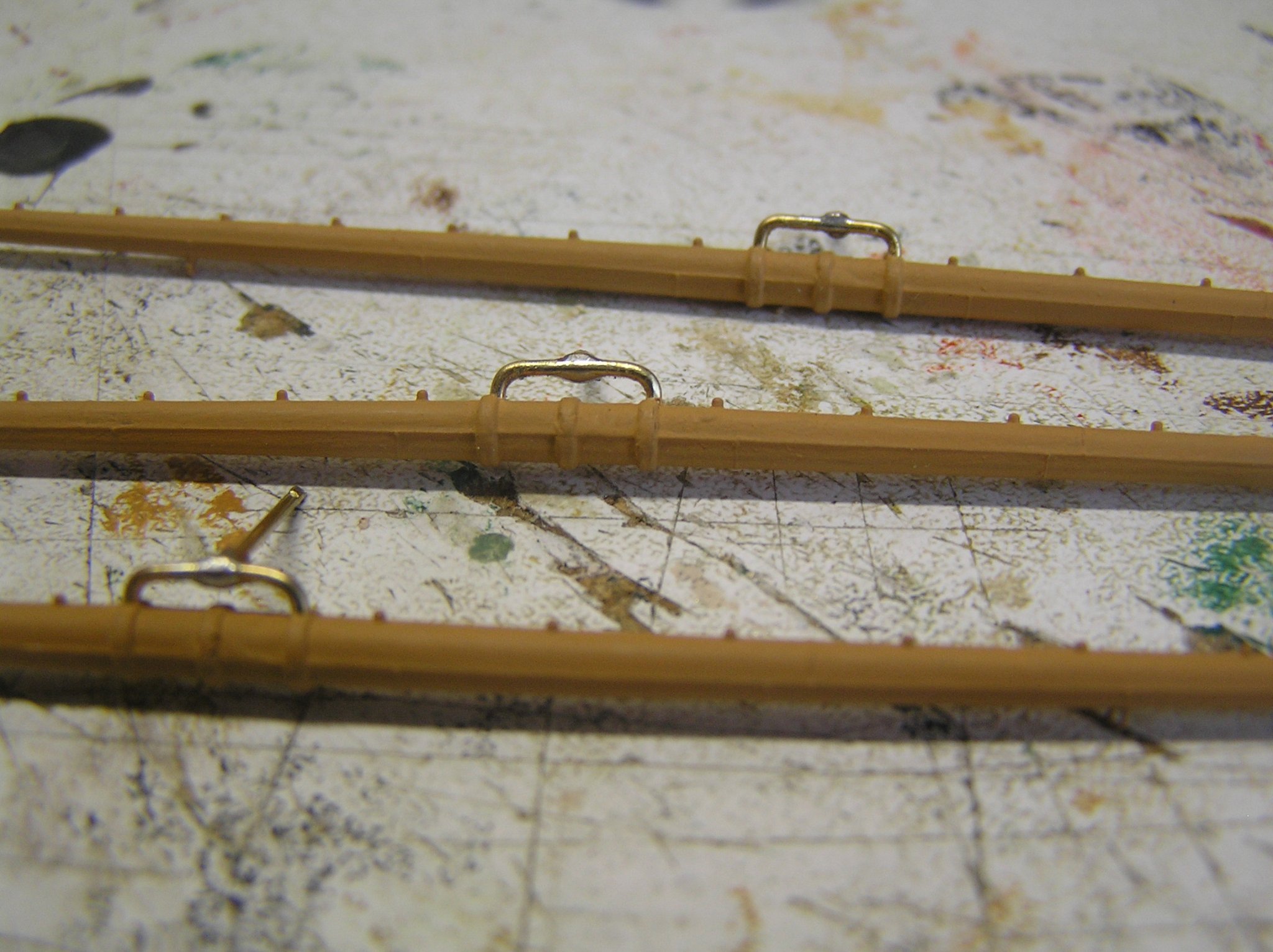
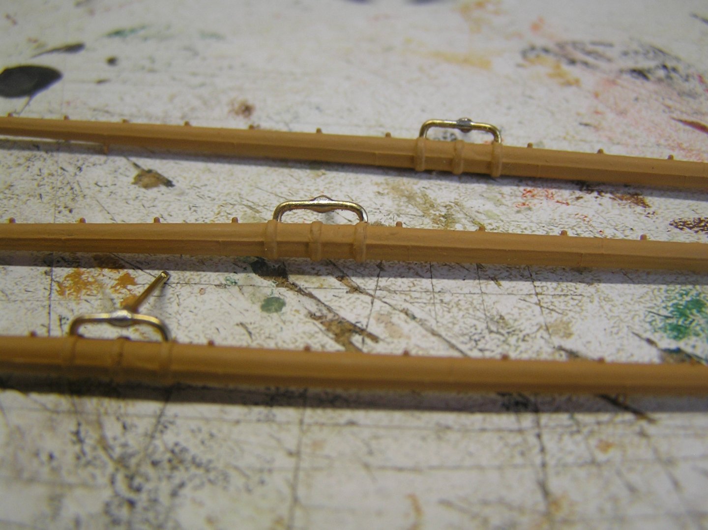
I'm back at Preussen after a long hiatus. Partly it was because of summer, partly because I spent some time developing arduino software to control the oars in an as yet hypothetical RC galley build. If interested the log for the rowing jig development is here: https://modelshipworld.com/topic/29294-arduino-code-and-rowing-mechanism-for-radio-controlled-galley/ I've been drilling holes in masts and upper yards to cross them, and adding yet more eyes on yards, mainly for sheets. The lower and lower topsail yards have larger eyes to accommodate chain sheets for the topsails. Bracing myself (no pun intended) to attach threads to the Jarvis and halyard winches so I can glue them on deck and get going on rigging. Wondering whether to try foot ropes at this scale. It occurred to me that I could use etch brass eyes for the stirrups, glued into yet more holes drilled along the aft edge of the yards. Kind of daunting for 30 yards. Still having problems blackening brass, and the copper chains. I made the trusses for the lower topgallant yards, which allowed the minor milestone of crossing all six yards on a mast for the first time. The topgallant mast is dry fitted. That's all I have to report at the moment.
-
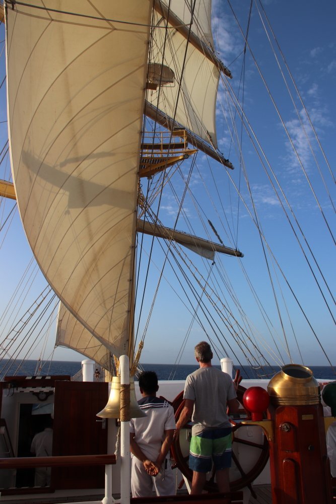
It's funny how you imagine a face for characters in novels, or people on the radio. None of you look anything like I had imagined. Somehow I didn't think of showing you this picture - me steering Royal Clipper one afternoon, under sail, all 5000 tons of her! What a rush, and talk about bucket lists! It certainly takes getting used to; you move the wheel and nothing happens at first then when she does start to swing the huge inertia is hard to reverse. We had just left anchor off a beach where I'd been snorkeling hence my bathing suit. She has a forward bridge. Note the missing fore lower topsail - it tore in a very heavy wind and the bosun repaired it the next day with the largest sewing machine arm I've ever seen.
-
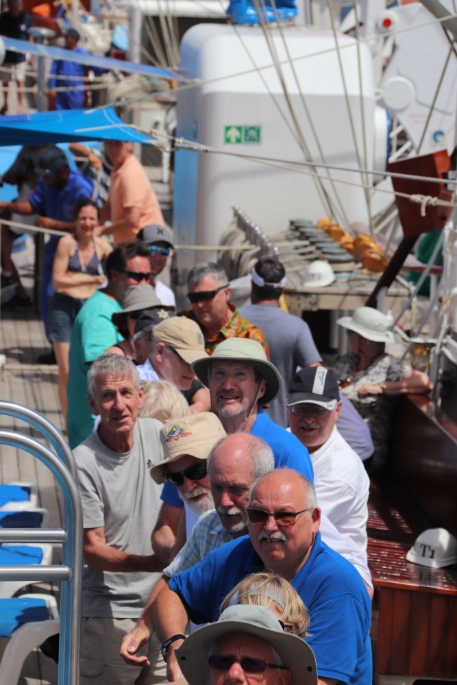
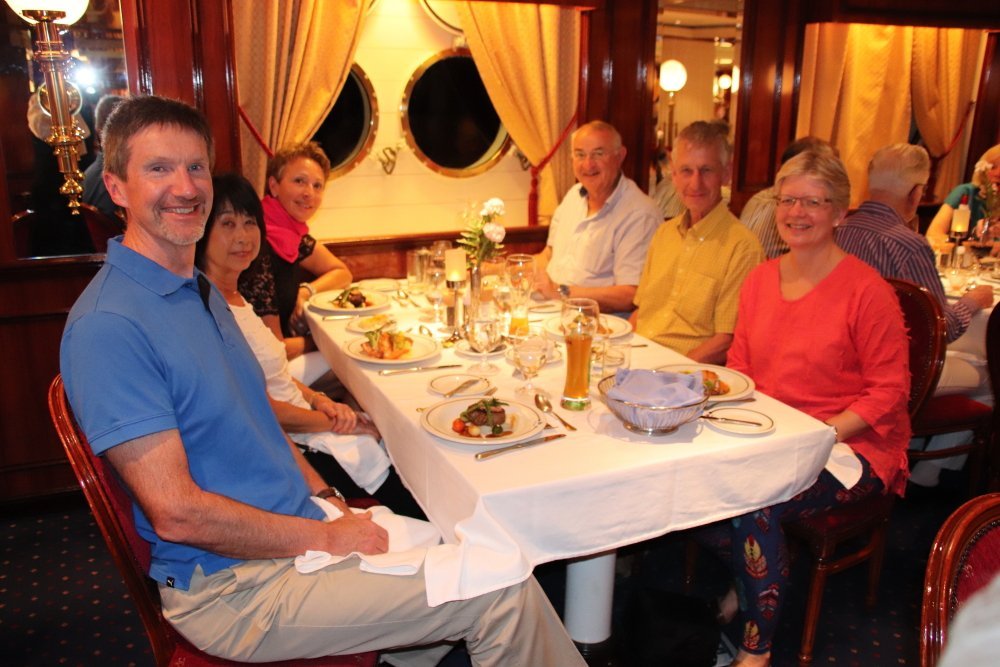
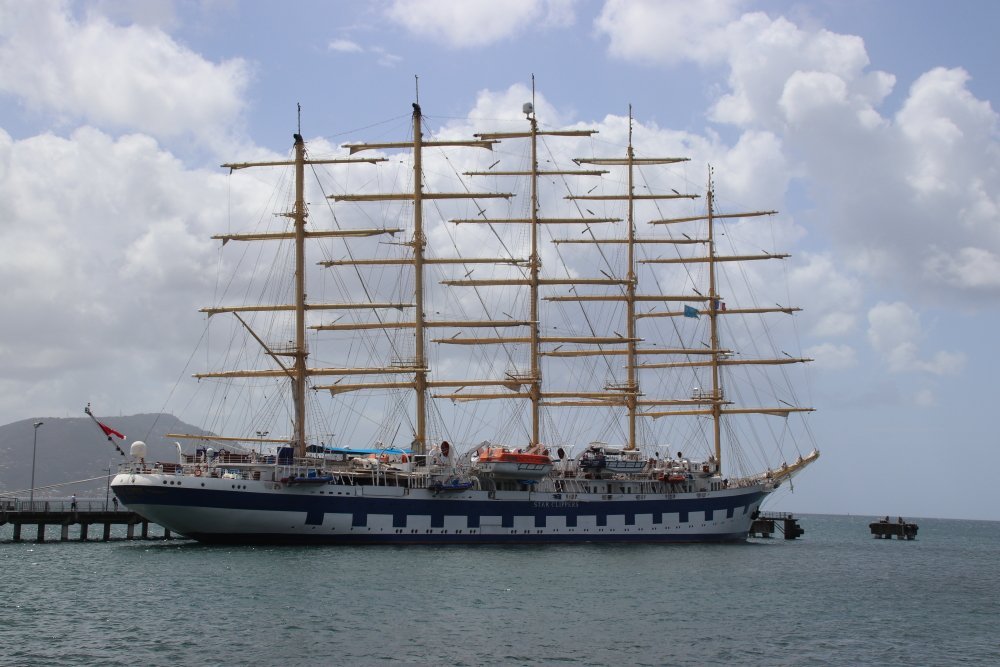
OK. Here's a picture; I am sixth from the bottom of the frame, tilley hat, grey beard, and blue shirt. Nowhere near as handsome as you Bill! 😁 We are busy hauling on a halyard to hoist a staysail aboard "Royal Clipper" . We took a cruise just before Covid. Awesome ship and we had a terrific time! I want to do an ocean crossing on her sometime. Oh, and hoisting just that one single sail was a workout! Second picture is one night at dinner aboard. I'm in the same blue shirt (??). Third is the ship herself quayside. Highly recommend a cruise, and no I have no affiliations with StarClippers.
-
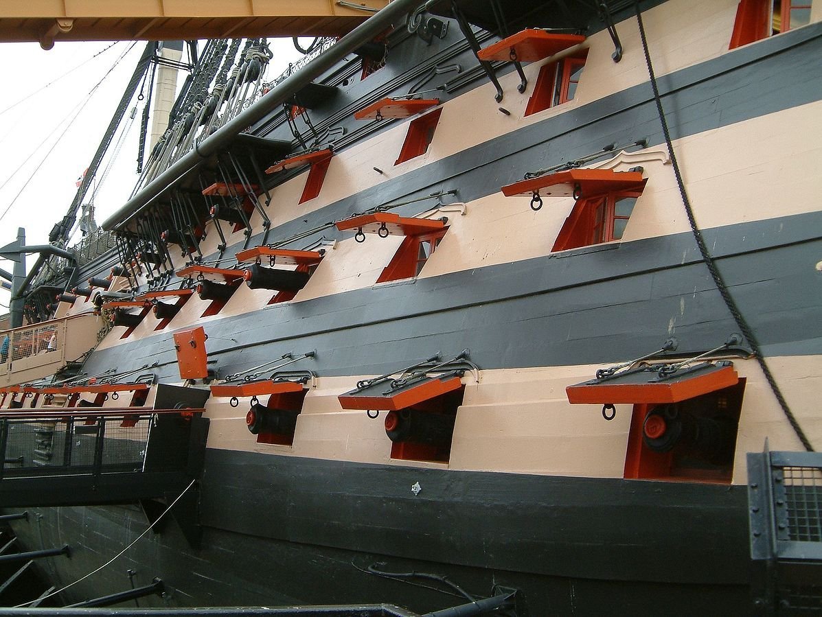
Bill, are you sure about adding evergreen to thicken the port lids? They are thin compared to the hull, only reaching into the shoulder around the port perimeter. I found this shot below, maybe you can get away with just thickening the lower deck ports.
-
Nice, but the brass etch ones are even smaller and cleaner, worth the money. Here is a rather poor photo I took of my lids with their inside eyes......
-
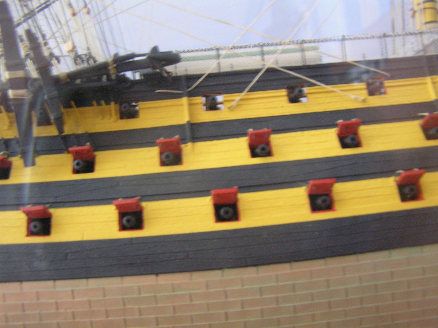
Yes, that's the so-called "chequerboard" appearance. I used etched brass eyebolts for the lids, two inside and two outside. The inside pair gives a good effect but you have to be looking very closely to see them 😆.
-
Nice job!!
-
Nice pond! Is that the model club's nice shaded launch dock or do people swim there too?
- 454 replies
-
- 2
-

-
- Union Steamship Company
- Stepcraft 840
- (and 3 more)
-
Whaaaaat? It's fixed already? I may just give up modelling given my slow pace 😀.
-
I ask out of interest knowing I want to do an RC model (my first in decades) once my current static build is completed: what do you use for ballast? Can one still buy lead whether as bars or shot?
- 454 replies
-
- 1
-
-
- Union Steamship Company
- Stepcraft 840
- (and 3 more)
-
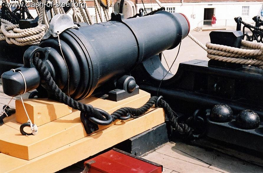
Dear Bill, I like your nets and hammocks......I hesitate to say, just tell me if I should stay 🤐from now on,..... there should be a gap in the forecastle netting in front of each carronade, just where the bulwark has the circular dip in front of the carronade pad on the deck 🤨. here is an image; you can see the black net ending on the right, that on the left is hidden.
-
Looking magnificent! I'm interested in your plans to transport her to water. What do you expect her to weigh, ballasted? Is a custom trailer next?
- 454 replies
-
- 2
-
-
- Union Steamship Company
- Stepcraft 840
- (and 3 more)
-
Great model and display! I've never tried a ship-in-bottle but can appreciate how painstaking it must be. Congratulations!
- 71 replies
-
- 1
-
-
- Charles W Morgan
- bottle
- (and 1 more)
-
I have adopted another orphaned kit
Ian_Grant replied to mtdoramike's topic in RC Kits & Scratch building
Mike, Are you sure that cloth is wetted out properly; or is that sanded white filler underneath it? Just askin' 🙂 Ian -
Paul, the challenge with finding thimbles is guessing what a supplier might call them, for the purposes of using their search engine. I used to buy them from The Model Dockyard, called "single hole deadeyes". but Nick retired and closed up. Take a look at "Cording Roller Wood" (???) at Model Dockyard (oops, corrected) Cornwall Model Boats; they have several sizes down to 2.5mm and 3.5mm. However their holes look perhaps smaller than on the ones I used to buy. Good luck! Ian
-
Thanks! It's been fun getting it to run, but now I have to get my head back into ship rigging in order to clear my none-too-large model bench for a possible galley build. Cheers!
- 536 replies
-
- 3
-
-
- Quadrireme
- radio
- (and 1 more)
-
Interesting! Thanks for that....
- 1 reply
-
- 2
-
-
Modified the software to incorporate Bedfords' suggestions. The return stroke speed is now multiplied by a variable "returnFactor" which I enter at the start of the program. I have renamed the variable which defines the pause at the end of the power stroke to "powerPause", and added a new variable "returnPause" which defines a pause at the end of the return stroke. The two can be given different values if desired. Zero is a valid value. In the video below, "returnFactor" is set to 1.5, and both pause variables are set to 5 which yields a pause of 1/10 second but is not really discernible yet. Some value between this and the previous 1/4 sec can be entered later during sea trials. I decreased the cruising strike rate (variable "CSR") to 24 strokes per minute but maximum strike rate (variable "MSR") is still at 40 which is a bit too fast.
- 536 replies
-
- 6
-
-
- Quadrireme
- radio
- (and 1 more)
-
Thanks Bedford for your interest and especially your suggestions! Yes, I entered 40 or maybe it was 50 strokes per minute for the top speed which is not humanly possible as the trials of Olympias demonstrated. But it just looked so s..l..o..w when I ran it at 30 😁... Yes again, I thought of changing the return speed but didn't get around to it before making the videos. It would be very easy to do in the code. Having said that, in a real model the sweep servos may slow naturally on the power stroke in the water compared to the no-load return. Sea trials would be required to finalize all the variables. Yes again, again, I enter a value for the pause at the start of the code, in terms of "number of 20 msec increments". It can be any integer value; the video uses "12". I went through this exercise to decide if a rowing model would be feasible. My conclusion is that a model could be built, and that software can be easily adapted to tailor the rowing motion to a model's in-water behaviour. So that's great. My one worry is about overheating the sweep servos. I'd definitely select a type with a metal housing, the better to conduct heat away from the motor. In fact, with my mind free-associating while walking the dog, it occurred to me that if I select waterproof servos for the sweep they could sit in an open well in the hull with their housing bottoms actually in the cooling water. 🤪 Not that I'm eager to have a big hole in the bottom of the boat......but if needs must......
- 536 replies
-
- 1
-
-
- Quadrireme
- radio
- (and 1 more)
-
I was probably 2.5 years in to get to where you are!😃 Well done!
-
Thanks for the tip! That works.