Ian_Grant
-
Posts
2,156 -
Joined
-
Last visited
Content Type
Profiles
Forums
Gallery
Events
Everything posted by Ian_Grant
-
 Marc, where did you find such tiny blocks? During my Victory build the smallest I saw was 2mm.
- 2,699 replies
-
- 3
-

-
- heller
- soleil royal
- (and 9 more)
-
Another wreck very well preserved in frigid water. https://www.smithsonianmag.com/smart-news/archaeologists-discover-an-almost-entirely-intact-142-year-old-shipwreck-in-lake-michigan-180982848/?utm_source=smithsoniandaily&utm_medium=email&utm_campaign=editorial&lctg=92646438
- 1 reply
-
- 2
-
-
Good God! And all this will be nearly impossible to see when model is complete! I second the mention of maybe doing cut-away model. I've seen many engines in the local airplane museum with openings cut in parts, with edges painted red to delineate them. It could be phenomenal, Chris!
-
"Wow" just doesn't cut it. Tackle hooks at 1/168 scale????!!!!!! In-cre-di-ble!!!!!!
-
Yes. nine a side. Each euphroe hole has to connect to a hole on the top each side of centre.
- 347 replies
-
- 4
-
-

-
- Sophie
- Vanguard Models
- (and 1 more)
-
Hi Bill. Good questions. I don't have definitive answers. I'll give you my impressions as formed by what little I know of seamanship. Two cents worth. Perhaps someone with more knowledge can correct me.... For the bowlines, I would expect that if in harbour, they would be removed to enhance a neat "harbour furl" of the sails. If at sea on a long blue-water voyage with the trade winds, perhaps not rigged either. If at sea in varying wind areas, then rigged. Staysails? We would have the halyards, downhauls, and sheets to deal with. If a staysail was not bent, I would expect that the halyard and downhaul would be left in place if at sea as above. Obviously the sheets would be absent as they only attach to the sail. I'd guess the halyard and downhaul ends would be attached to each other or else both attached to a convenient point at the foot of the stay, If one wanted to bend the sail, one would haul it up to the foot of its stay and attach it by its hanks; then attach the halyard and downhaul to the head of the sail before hoisting it up. The "tack" would be a simple length of rope from the foot of the sail to a fixed point at the foot of the stay. I believe the common thing to do on a model is either omit everything, or rig the halyard and downhaul as one continuous piece of thread or optionally as two pieces with their ends joined at a representative knot. I looked in "Harland" and "Lees" for more info, but Lees is detailed in rig and short in explanations. Harland has staysail tidbits scattered throughout but nothing as detailed as what you ask, that I could find. Staysails always seem to be an afterthought in books; for instance Harland has an entire chapter on studding sails but no section on staysails. Even Longridge as you may recall lacks his usual detail when it comes to staysails. Yours will be a beautiful model either way. Regards, Ian
-
Richard, I know you will come up with a few ingenious jigs for the job. I used three to produce oars for my galley, but I only had 88 to make. 😏 This is one of the most impressive builds on MSW, absolutely!
-
A true work of art!
-
Where does one find such figures as a little girl wearing a gas mask and holding a teddy bear? Or a dog in a gas mask? Great model, great diorama, great imagination! Your work "goes to 11".
-
You're making a beautiful job of her Glen!
- 301 replies
-
- 7
-
-
-
- Constitution
- Bluejacket Shipcrafters
- (and 1 more)
-
Amazing work as always, Michael. Is the handlebar on the fish davit etched brass eyelets with wire? Or did you work up something even smaller, for the scale?
-
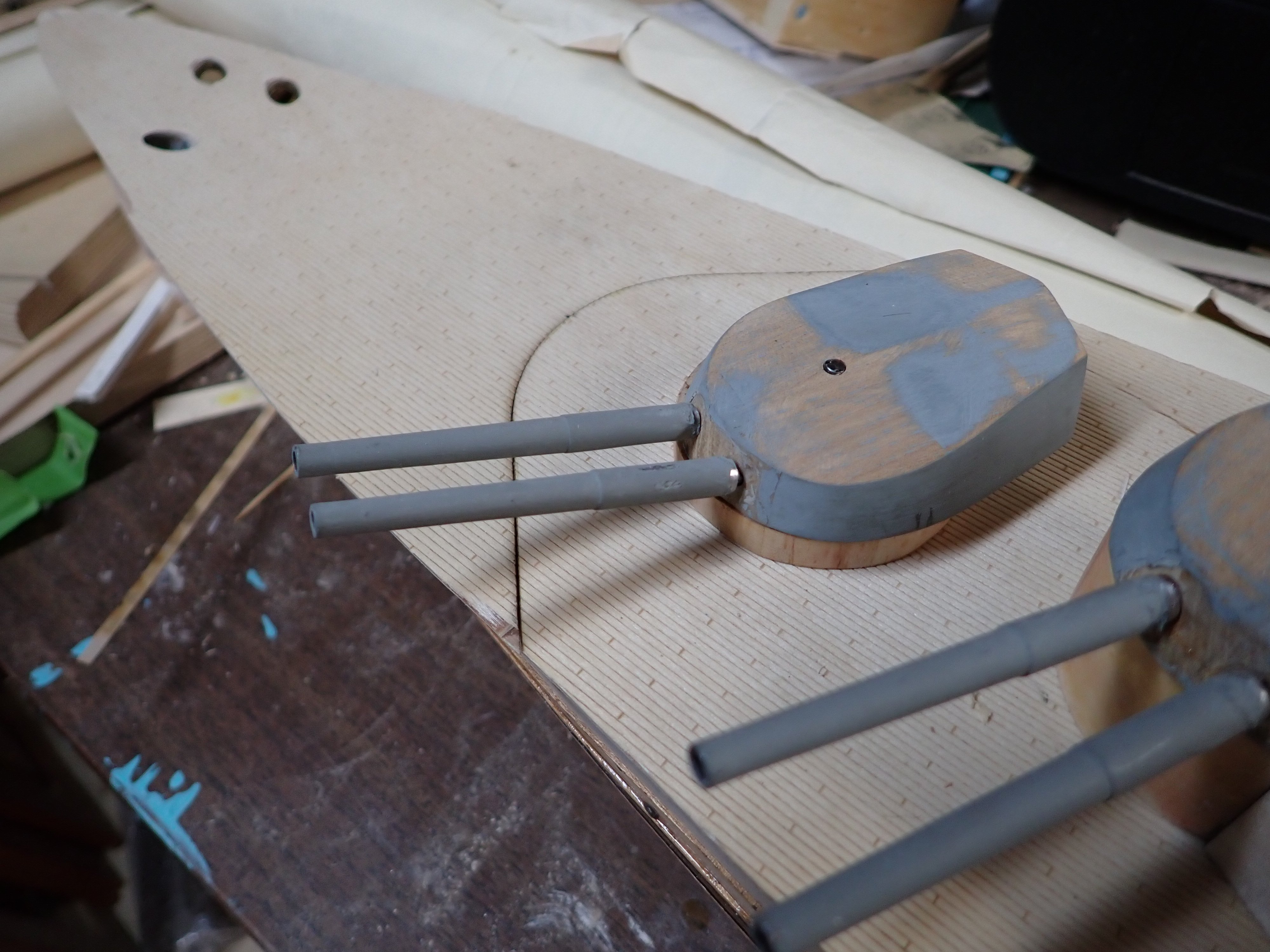
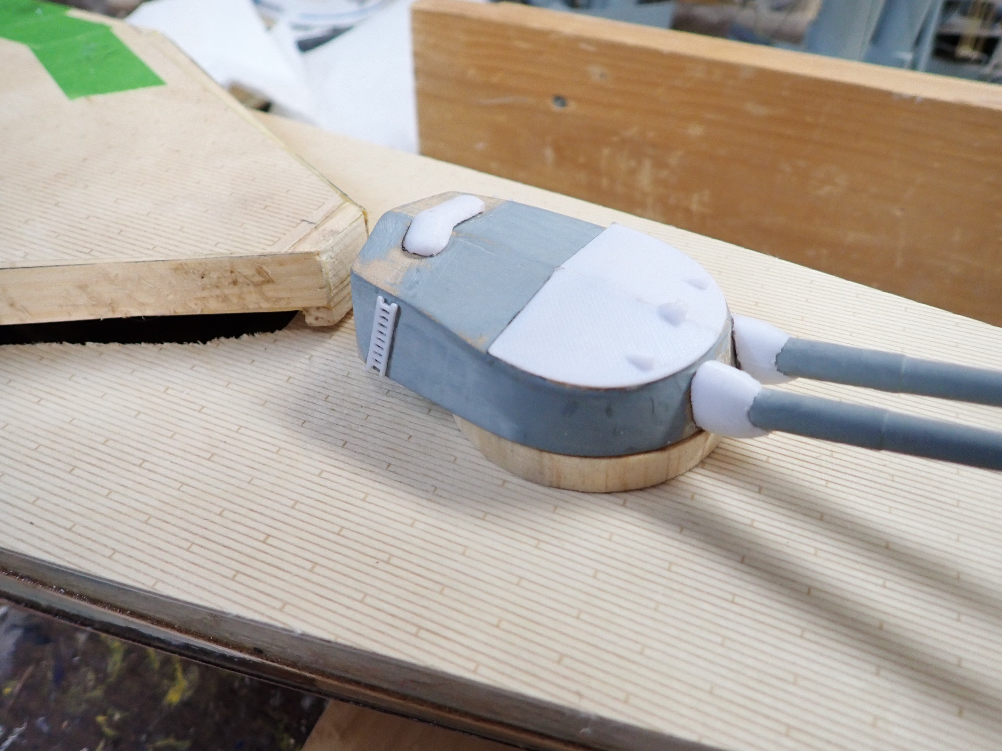
Working on turret enhancements that teenaged Ian skipped. I printed two quarter-circle tapered parts to bring up the top of the front edge and also add the sighting hoods. Then I printed some little wee ladders, and some what would you call them, weather-protective canvas bellows?, for where the guns emerge from the turret. Here's an original turret. Notes (1) the hole in top is from me re-drilling to get a more accurate axis location, (2) teenaged Ian wrapped some large-dia solder around each barrel, since removed, and slapped on some grey paint. Here is "X" turret with enhancements; further fettling and filling required. By the way, I seek opinions on the grey that teenaged Ian used. The drawings have a note saying she was "medium blue-grey" but this looks too blue to me now. I bought a lighter grey which looks ok in the shop, but is very pale in daylight. Suggestions?


-
OK sorry; didn't realize this was already posted. Should I delete this topic?
-
Kind of tangential topic but may be of interest to some members: https://www.smithsonianmag.com/history/abraham-lincoln-only-president-have-patent-131184751/?utm_source=smithsoniandaily&utm_medium=email&utm_campaign=editorial&lctg=92646438
-
Lower yards are not readily lowered, normally, except by jeers which your AOTS diagram does not show. As for lower lifts, they have to run forward of the shrouds,no choice (they can't run through them). When the lower yard is braced round, the windward end will be further forward and its lift goes nowhere near the shrouds; on the other hand the leeward yard end will be abaft the mast and they'd have to slacken that lift to prevent it twanging against the forward shroud. I expect the only time both lifts are nice and taut is at anchor when the yards are squared for appearances, or maybe when running before the wind.
-
That is a puzzle Bill. I have little to offer here. Is that AOTS book specific to Endeavour? That diagram has #2 pointing to both sides of the rope through the block, suggesting that the sling is just looped round the mast with the running end passed through the spliced eye then seized to itself. Not sure why the block is needed/used. Other than the block it's sort of normal. Not sure what occre wants you to do. They seem to want a halyard on the lower yard, not a sling. Haven't seen that before. Maybe on merchant ships? Maybe have two halyards; each attached at the heel of one of the single blocks , running through one sheave of the double block, then up through the other single block and down to deck? Not sure what else to suggest. I would tend to trust AOTS over occre, though maybe I'm biased given my past experience with Heller instructions? 😏
-
That's the plan, but I don't think the total mass of superstructures and RC is a significant enough fraction of the hull displacement to make much difference. I left it needing two or three of the old metal rectangle pieces as adjustable ballast so I do have some leeway. If I ever change to brushless motors and NiMH pack, there will be a LOT of extra ballast needed. Hoping the 50-year-old brushed motors are ok. 🫰
-
Lead shot ballast added according to the results of the flotation tank test (why is it "float" but "flotation"?). Compartments with lead were "capped" internally to stop lead from shifting around. Foredeck added. Before adding aft deck I needed to get "X" turret rotation sorted. Here's a quick video of the four turrets rotating together. Now I can add the aft deck and get going on the aft superstructure. I am now working on printed additions for the turrets, which fix the turret fronts which dipped a little low, and add the three sighting hoods. There's also a hatch or something shown on the drawings at the top rear of all turrets except "A". Not sure what they are as they seem too low to be rangefinders, and are asymmetrical from side to side. (??) The 3D rendering has imaginative apparent rangefinders here but this is not in the photos of Lion in my book, even in 1918 after wartime modifications. Also need to decide whether gun barrel holes need to be plugged and re-drilled slightly higher. HMS Lion Turret Rotation.mp4
-
Yes; if you ever build a Heller Victory there is much extra prep work before starting the rigging. For example, Heller's instructions have no means of holding the yards to the masts; in the case of the lower yards you need to add blocks at the feet of the masts for truss pendants. As you say this is much easier before the masts are even stepped. The Heller Victory instructions are diabolically bad.
- 301 replies
-
- 4
-
-
- Constitution
- Bluejacket Shipcrafters
- (and 1 more)