Ian_Grant
-
Posts
2,156 -
Joined
-
Last visited
Content Type
Profiles
Forums
Gallery
Events
Everything posted by Ian_Grant
-
 Fantastic - immaculate - not a single glue mark!!!!
 -
Great job on the pikes. I expect to see them on your upcoming SIB too, mind! 😁
- 301 replies
-
- 3
-

-
- Constitution
- Bluejacket Shipcrafters
- (and 1 more)
-
Too bad you're on the opposite side of the world......I have two copies! I thought I'd lost the first, bought the second, then found the first months later. I suppose I should try to sell it on. It's a limited market.
- 201 replies
-
- 1
-

-
- Flying Cloud
- Mamoli
- (and 1 more)
-
Harry, do you have a copy of Underhill's "Masting and Rigging the Clipper Ship and Ocean Carrier"? A great reference for such ships. I bought it to help with rigging my Preussen.
- 201 replies
-
- 1
-
-
- Flying Cloud
- Mamoli
- (and 1 more)
-
Nice print!
-
Rigging looks daunting, but as you go through it in manageable pieces it all comes together in the end, so long as you have good instructions. 😏
- 201 replies
-
- 1
-
-
- Flying Cloud
- Mamoli
- (and 1 more)
-
She is is very shipshape and really looks the part of a naval vessel, Glen. Immaculate!
- 301 replies
-
- 3
-
-

-
- Constitution
- Bluejacket Shipcrafters
- (and 1 more)
-
Well done, Bill. She looks wonderful! Looking forward to your AV build; seems quite a bit more complex than Endeavour....
-
Seems to be a very small aircraft; kind of stubby.
-
Great work, Glen. Your clients will be thrilled! Ah yes, mai tais. I don't have much experience with cocktails but I discovered the mai tai while in Hawaii. And the pino colada while on a boat in the Galapagos. My two favourite (and almost my only) cocktails...
- 301 replies
-
- 5
-
-
- Constitution
- Bluejacket Shipcrafters
- (and 1 more)
-
I always get that flaky finish too! And I too dump the chains into the solution. I will try your new method. Thanks Keith!
- 732 replies
-
- 3
-
-
- Lula
- sternwheeler
- (and 1 more)
-
The other thing about chains which drives ME batty is blackening them. I have had little success. 😞
- 732 replies
-
- 1
-
-
- Lula
- sternwheeler
- (and 1 more)
-
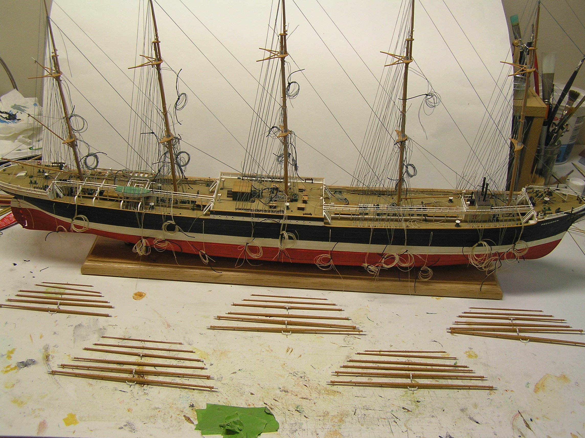
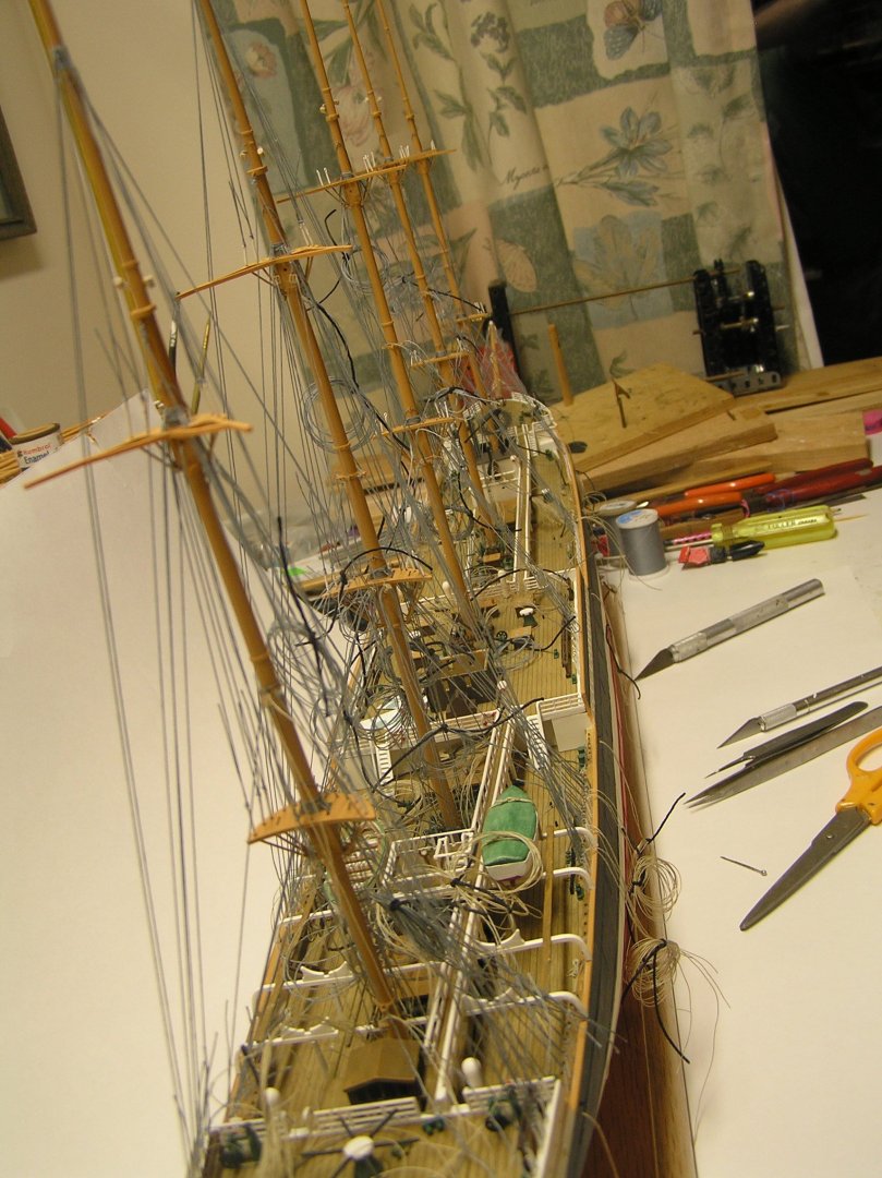
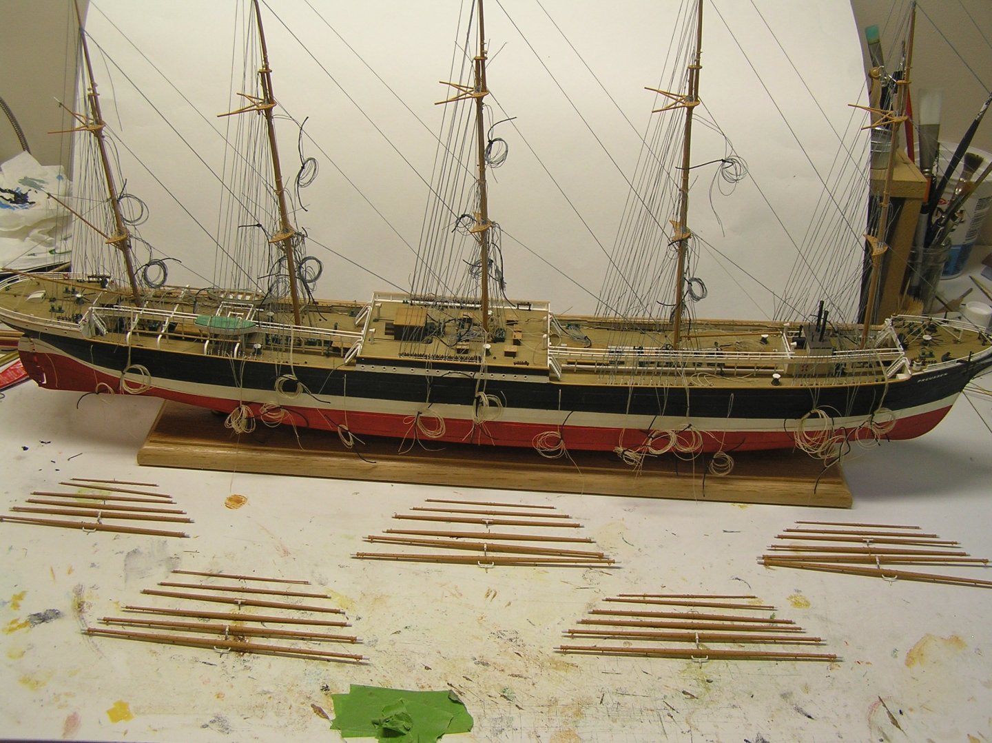
She's looking great, John! But I don't seem to see the scramble of unsecured rigging?? Here's a shot of my Preussen build.........😏 (paused about three years now) 😞
-
I ran across this article on dazzle paint in WWI. I added a topic in "Nautical/Naval History" but thought I'd mention it here for those who don't commonly browse that forum.
-
Interesting article examining whether dazzle patterns had any real effect on U-boat targeting of ships in WWI. https://www.popsci.com/technology/wwi-dazzle-camo/?utm_source=firefox-newtab-en-us
-
- 3
-

-
-
Interesting to see it come together. Not to diverge too much from this log, but in my handyman days I was once hired to "restore" a large L-shaped basement area where the lady's deceased husband had run his model RR along with his friends. This area encompassed half of the basement of the house. RR track completely encircled the room (except for one doorway) with as much as three feet depth from the walls, which were adorned by very skilfully painted hills and trees (I know this because I saw the area before the husband's friends came to remove the whole thing to another location). Anyway, when I went back for the job the walls were riddled with large jagged holes where they had apparently just ripped stuff off them as opposed to unscrewing. The lady was surprised when I proposed to just patch everything up rather than install new drywall but that would have been a big job and I was getting too old to be lugging drywall sheets down stairs any more. It was one thing to patch and tape the holes (and build a little closet around the incoming water valve) but effectively hiding all the painted forests took about four coats of primer. The finished job delighted the lady with the fresh new room. I've found that one advantage of doing a job for senior ladies is that they keep you fed while you're there! 😏 Now back to our regular programming; sorry.
- 303 replies
-
- 10
-
-
-
Every summer our RC boat club puts up a table pondside at a local fair and runs boats around. People come over to see the models all lined up on a long table and are really interested. Well, I guess only those interested would come over HaHa. Last year I took my Roman galley (didn't have it on the water, too windy) nonetheless people were fascinated to see the oars rowing. It was great talking to them and showing how they worked.
- 732 replies
-
- 6
-
-
- Lula
- sternwheeler
- (and 1 more)
-
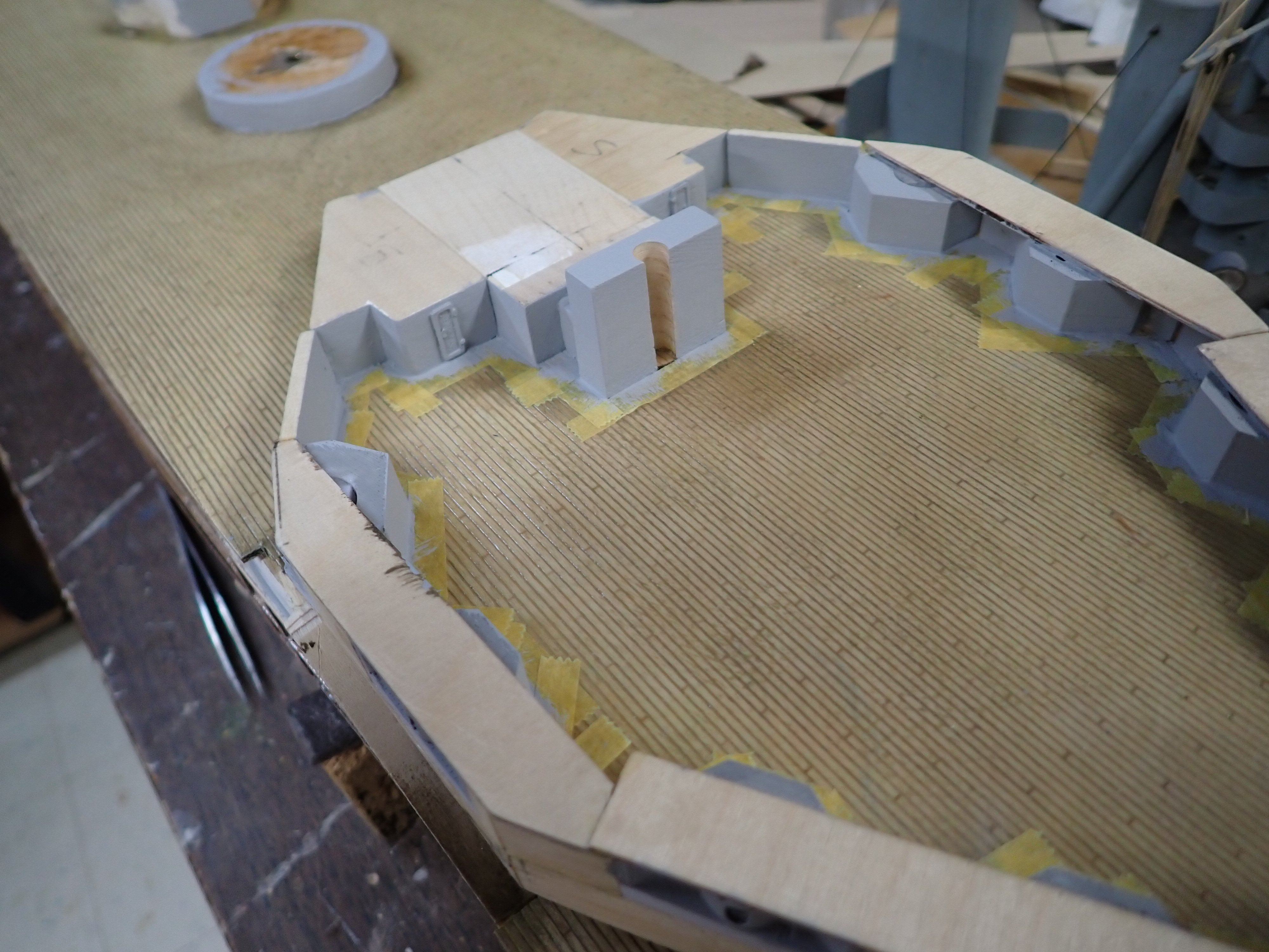
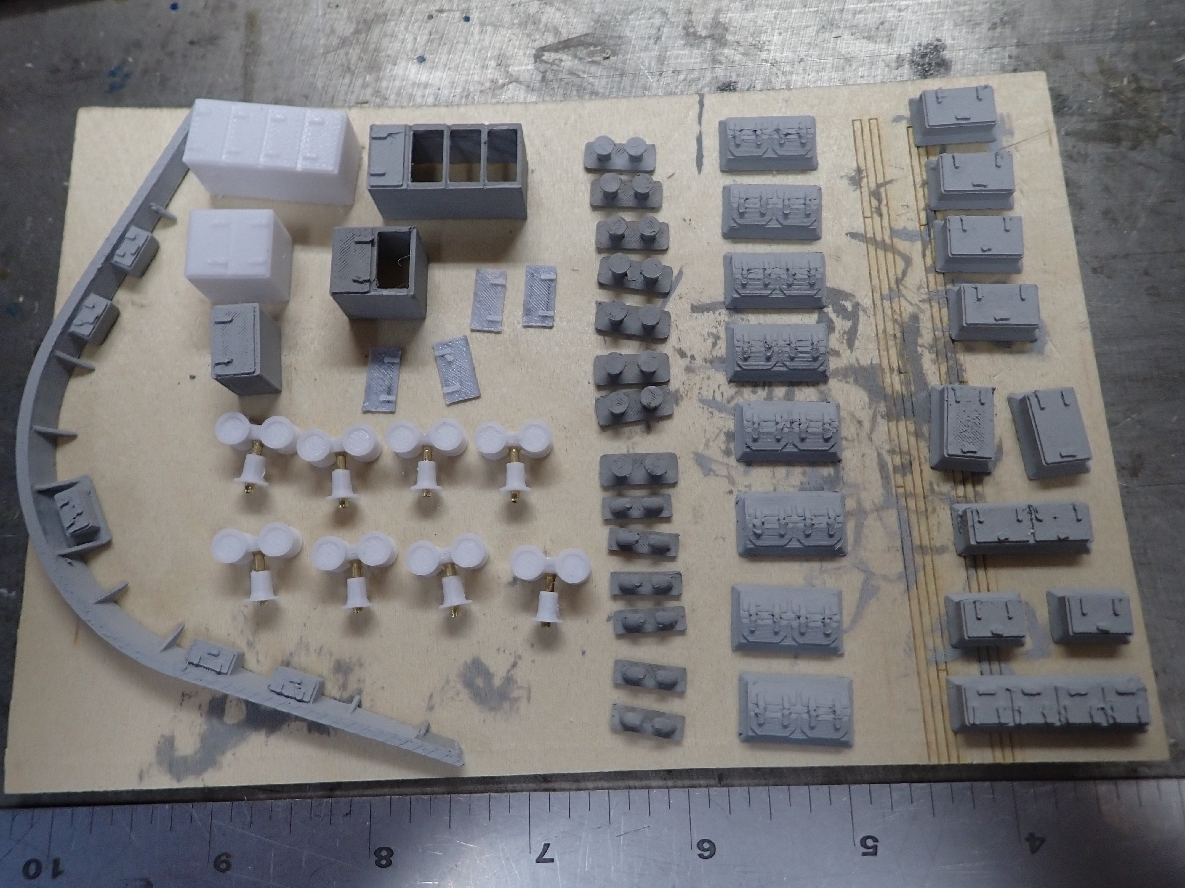
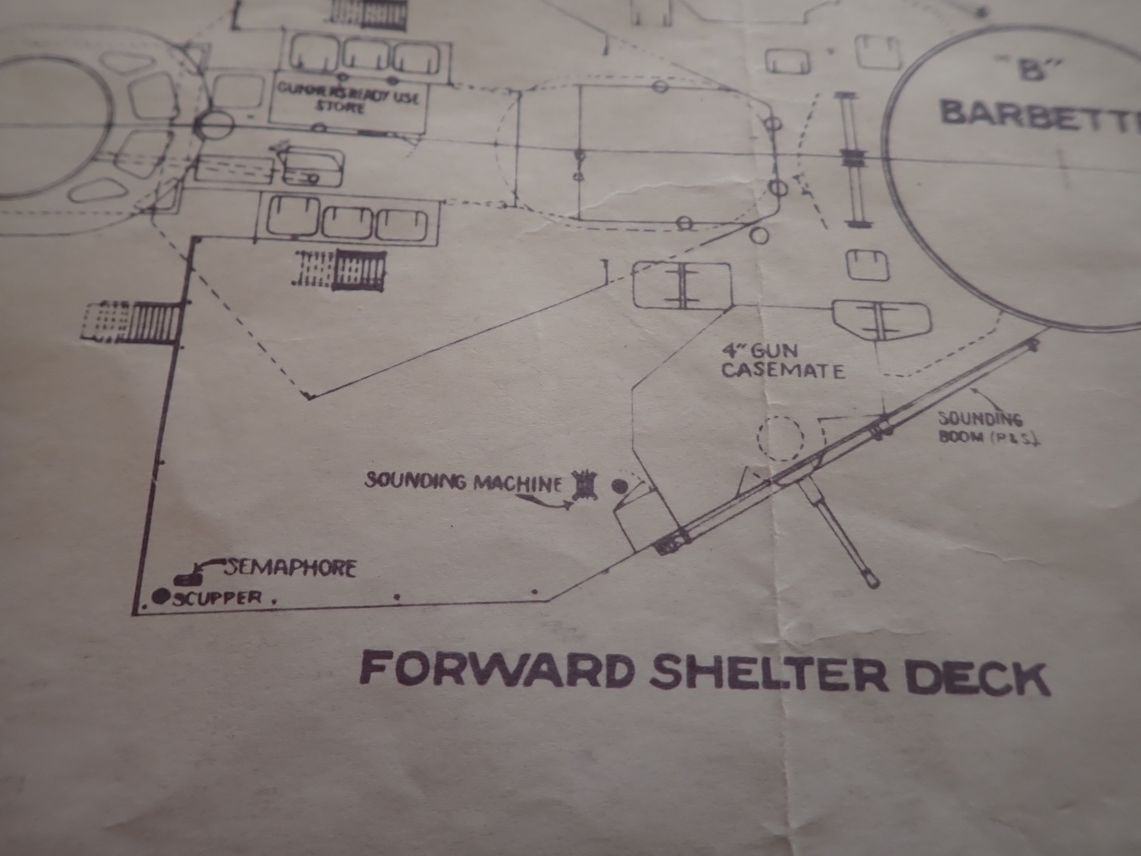
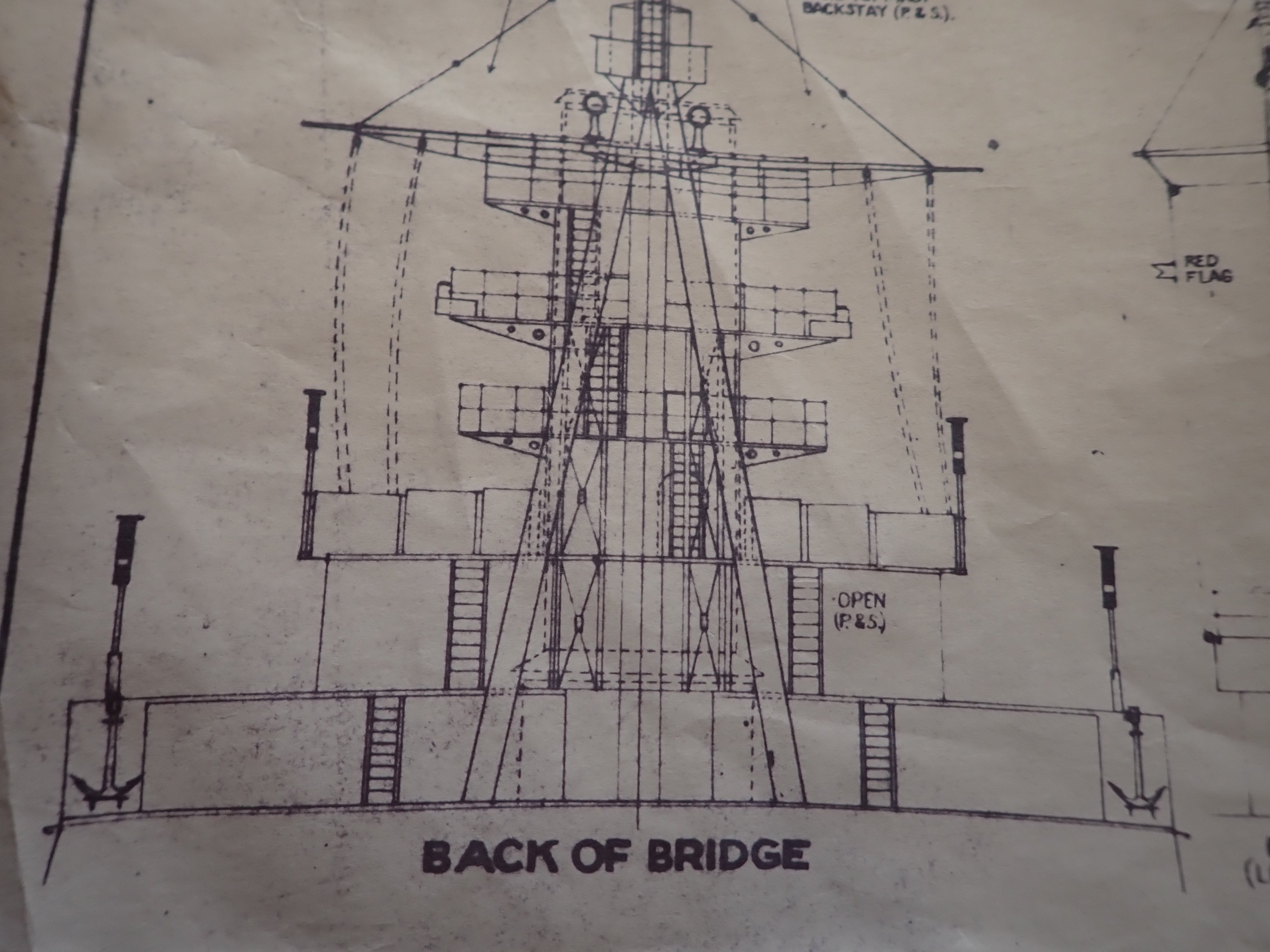
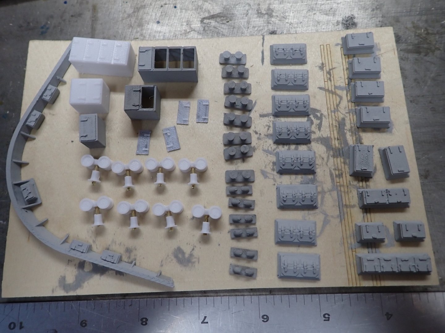
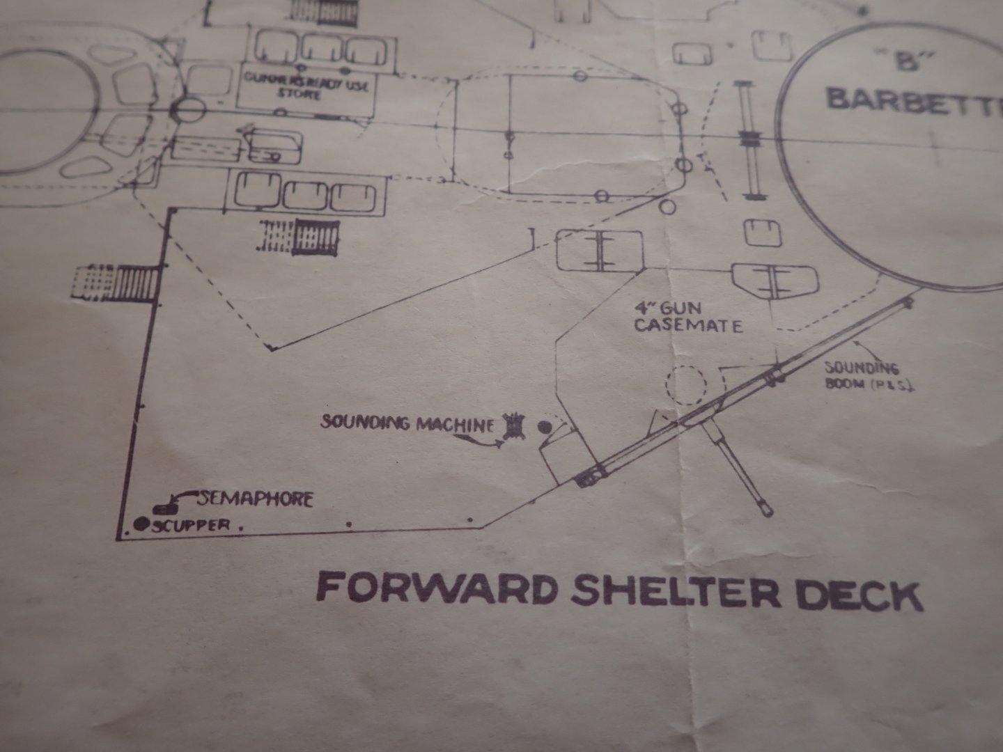
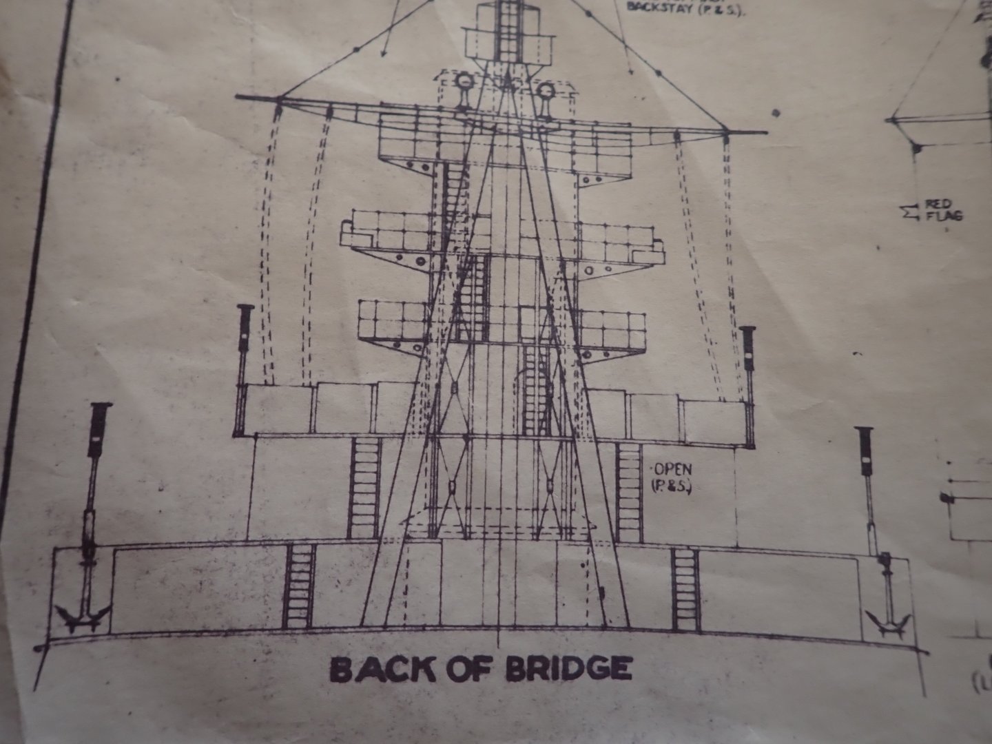
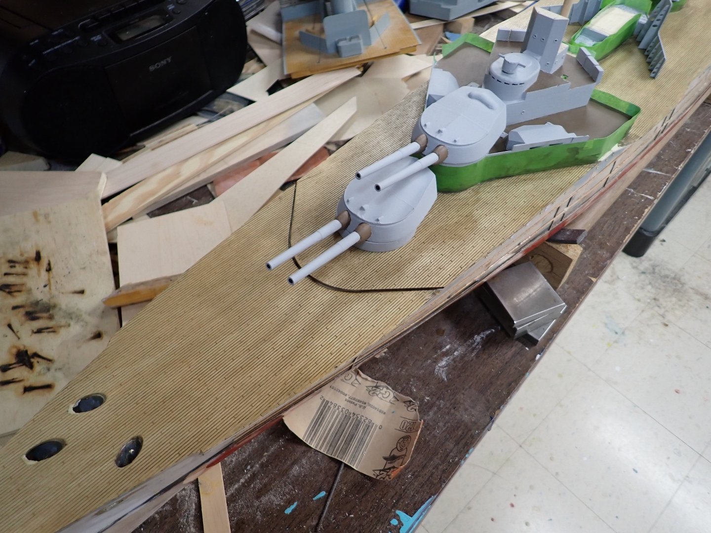
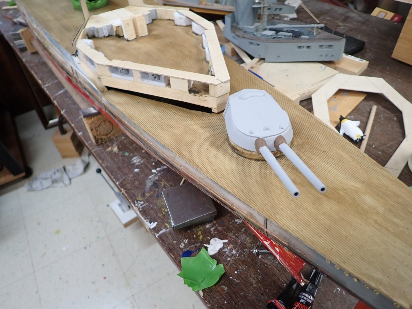
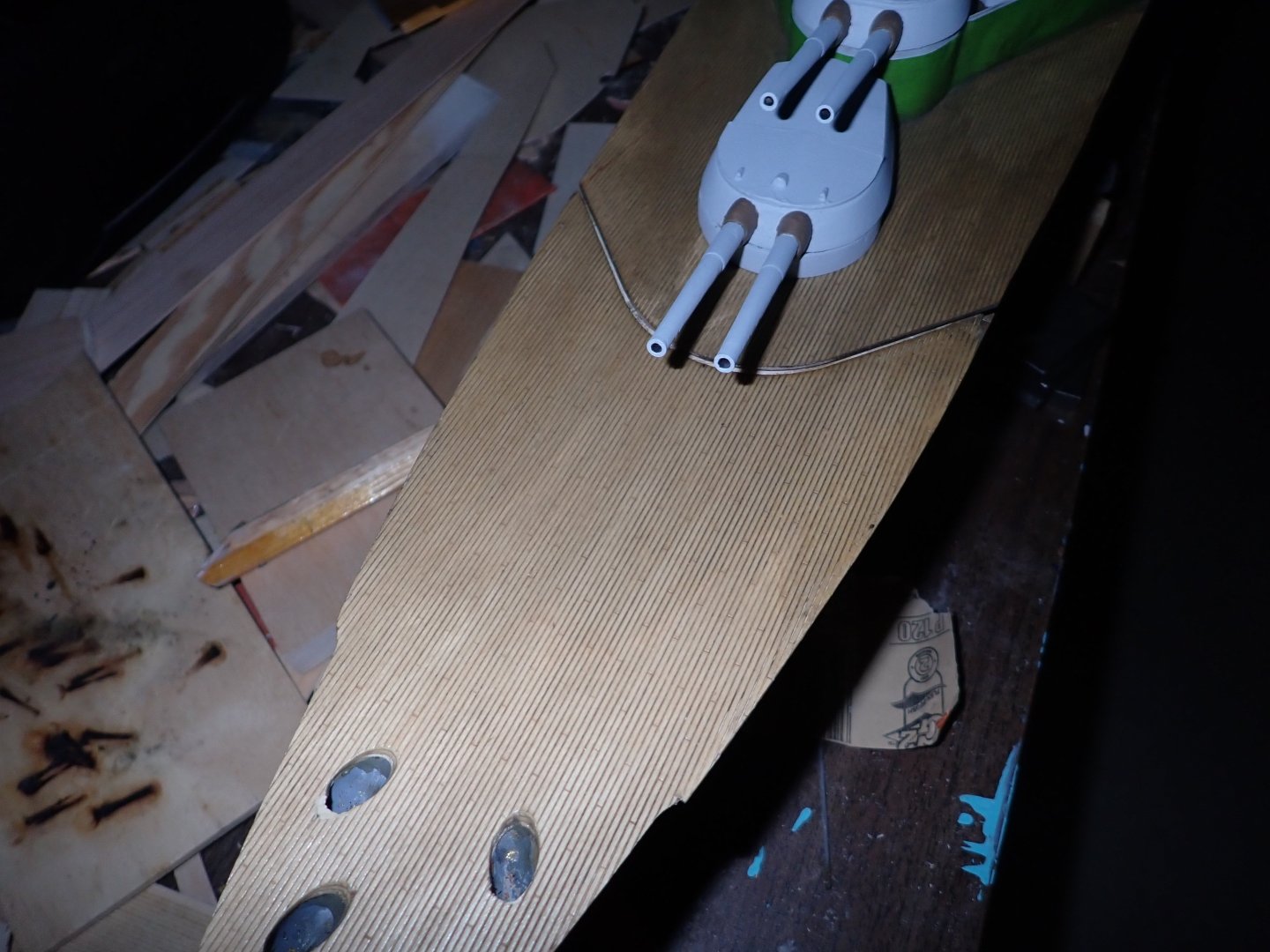
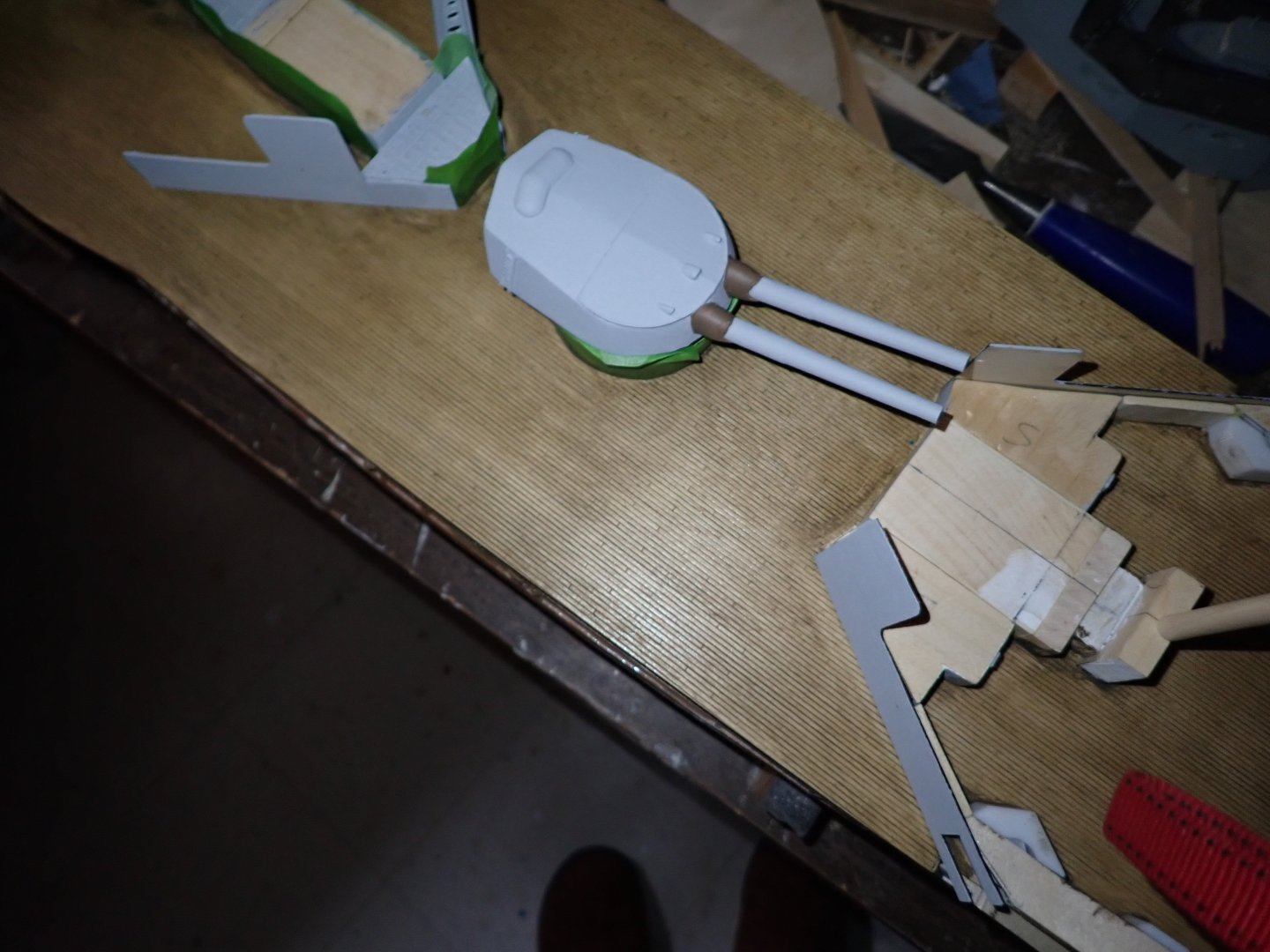
I got up the morning after my last post, walked downstairs, and my immediate reaction to the deck was,"God it's awful!". I bought some "white spirit" and wiped down the decks with it thus removing all the yellowish tones and most of the dark brown. The laser-etched planking once again became readily visible. Whew! I was left with a faint, weird "greenish tone" in places. Don't know where that came from; seemed to be highlighting the grain of the surface ply even though I had four coats of clear-coat on it, somehow. So I used the "desert sand" wash one more time, then a wash with "white" and I like the decks a lot now. They have received three coats of exterior satin water-based varnish. I know, it should be matte, but I can't find an exterior matte clear-coat. Here's a pic showing part of the decking, and also the interior "walls" of the aft superstructure which will be visible since there is a large well deck here. Teenaged me missed the fact that it was open; I don't blame me because it is not obvious in the single sheet plan and top view drawing. Rather, it is shown only in one of the cross sections in the lines drawing which I probably rolled up and ignored after making the hull. Incidentally, I'm not sure what the secondary armament looked like in the aft well deck. Norman didn't show casemates for them (like the upper pair in the forward SS) but if they were open the crews could all be killed if a single shell landed in the well deck I would think. I decided to add casemates partly because they're not conspicuous when viewing the ship from outside, and partly because I didn't want to have to construct the gun breeches in the absence of casemates. Close enough for RC. 😏 I'm now working on printing weather deck fittings. From left: - breakwater for the foredeck. - top left, engine room vents for the aft well deck, "closed" and "some open" options. - below left, twin searchlights; printed housing and base, brass rod. - printed bollards and cleats. - printed skylight covers, all closed. Thinking of making a couple with steel covers open. -various printed hatches for the weather deck I'm thinking of starting to paint the hull tomorrow. That would be a giant leap ahead for sure. Incidentally, does anyone know if these ships had some sort of mechanical semaphores for visibility? My drawings show items labelled "semaphore" in four places in the forward superstructure (two at back corners of the shelter deck, two on the flag deck above). They aren't shown in detail but they could be a mechanism with the arms folded down, not in use. Or are they just big signal lights to flash Morse, not related really to a man manipulating two tiny flags?? Can't find anything about it in what books I have, or by a brief google search. Here's a pic or two: 1) Showing a semaphore placed in the corner. 2) See the four of them in this section view. They're a good 10 ft tall, whatever they are. They look more like lights here.

-
Interesting discussion. Here's a theory .... When coming in to harbour they'd be under topsails alone, probably. Knowing they were about to anchor they could remove the bumpkin shrouds. If when anchored the tide was across the wind or whatever the anchor cable could be at any weird angle without fouling the absent shrouds. As to whether Endeavour herself had bumpkins, I have no idea.
-
Today I bought a Vallejo wash "Desert Sand" and have applied it three times. It adds a yellowish tone and is making a difference. It looks pretty good to me now but in the morning I'll probably apply the wash a 4th time. It only needs 20 min to dry, 40 min to recoat. I bitterly regret, though, applying that dark wash just because it was in stock at the local store. The really foolish thing is that yesterday I forgot my reading glasses so I could barely see the labels thus I missed the Vallejo washes entirely; there are just a few wash colours at the bottom of the Vallejo paint rack and their labels don't really differentiate them from regular paint colours. 😞
-
"Ironton" wreck 1894 located in Lake Huron STILL WITH MASTS
Ian_Grant replied to Ian_Grant's topic in Nautical/Naval History
I'll say. I used to go shipwreck diving at Tobermory in the 80's. When we took the kids camping up the Bruce about 15 years ago I was amazed to see the water clarity in Georgian Bay. It looks like the Caribbean now, that is until you jump in. -
Plugging along slowly. I shopped for a wash to apply to the decks. I like MIG washes but the only local source was stocked out on them. I ended up buying AK301 "Dark Wash for Wood Decks", only because the local stores are out of AK263 "Wash for Wood". I'm not sure I like it; maybe too dark. Opinions? The camera has lightened the colour in the above shots. If it truly looked like that I'd be pleased. Here's the best I could get on trying again; in the dark with the camera's LED on. LED glare is the whitish spot near bottom centre. Deck's true colour is best seen beside Q turret and between it and the blast shields behind it. True colour is near turret not ahead of the deck split.
-
Another day, another Great Lakes shipwreck announcement.......... https://www.smithsonianmag.com/smart-news/ironton-shipwreck-lake-huron-180981741/?utm_source=smithsoniandaily&utm_medium=email&utm_campaign=editorial&lctg=92646438