Ian_Grant
-
Posts
2,156 -
Joined
-
Last visited
Content Type
Profiles
Forums
Gallery
Events
Everything posted by Ian_Grant
-
 Agreed.....I just bought a 3D printer capable of printing large sections of a ship's hull. Would be way cool.
 -
Loved Hawaii. Recommend taking a beginner surfing lesson for fun! Have a great time!
- 301 replies
-
- 5
-

-

-
- Constitution
- Bluejacket Shipcrafters
- (and 1 more)
-
No, you can't have seen it because I grew up in Bramalea just north of Toronto airport. Moved to Ottawa in 1981 after university but Lion hasn't seen water since. I just started on ship models again a few years ago and only joined the local RC club last year.
-
In the case of Glen and his wife, "junk item" could be construed as "a short section of railway track".
- 185 replies
-
- 7
-

-
-
- Flying Dutchman
- Black pearl
- (and 2 more)
-
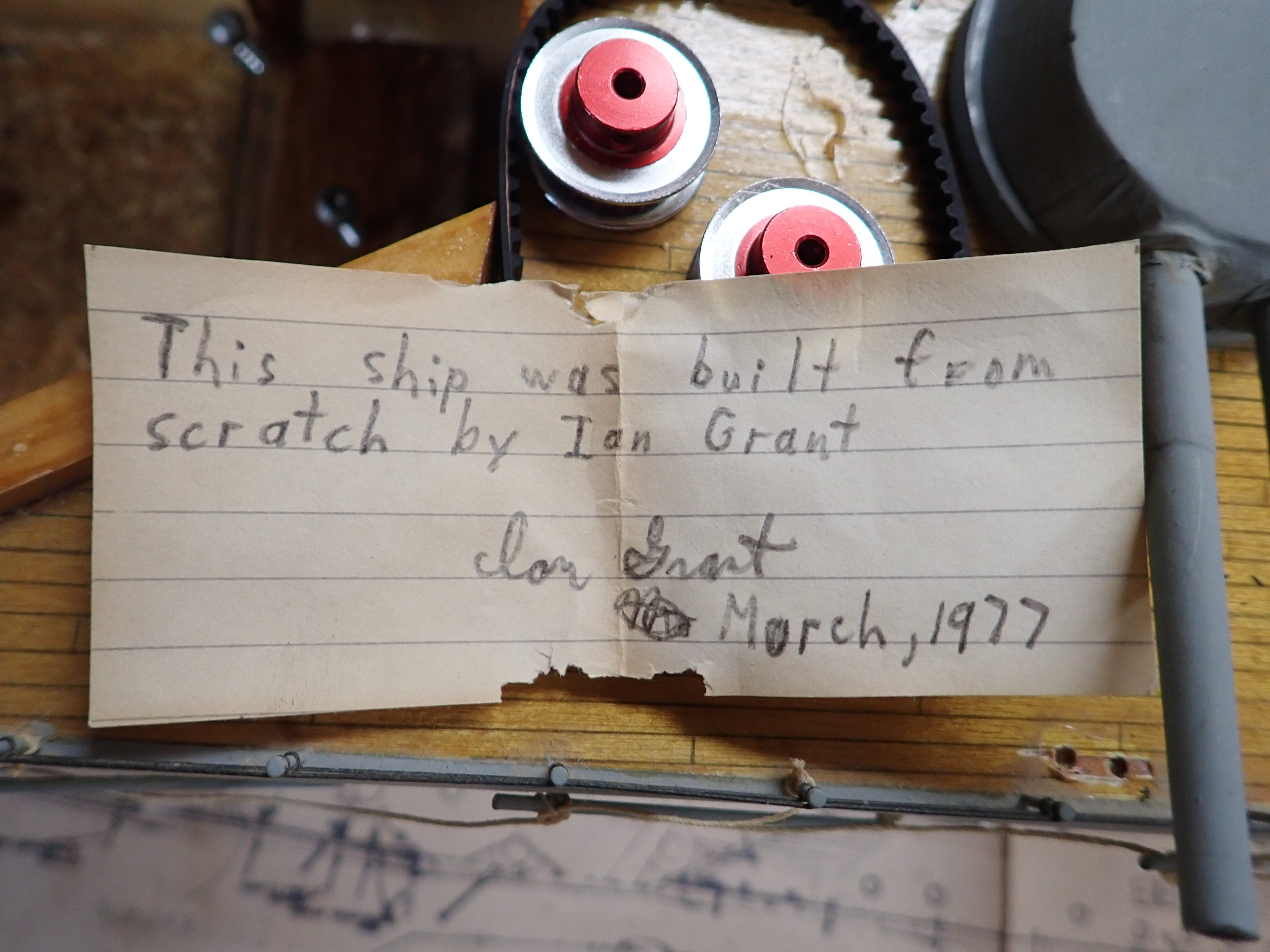
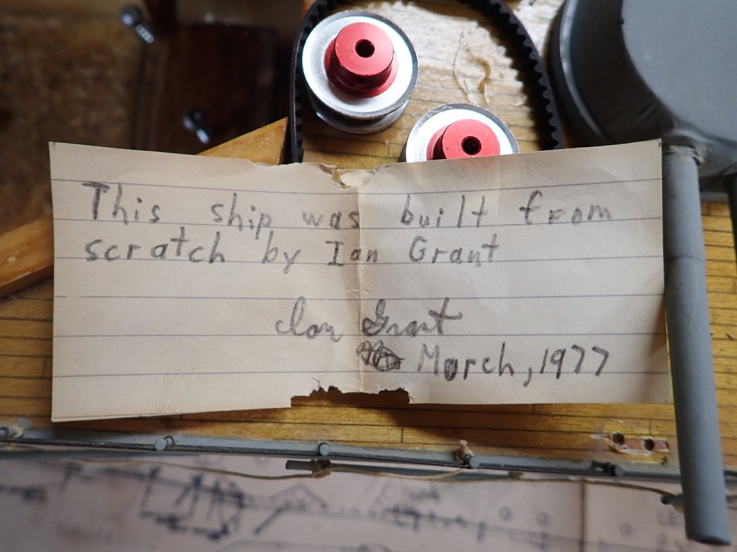
Yes it was nostalgic to find the note, and remember my young self. When the time comes I will put the note back, along with a new one dating the rebuild. Full disclosure: build quality was helped by my dad. He turned the main gun barrels from aluminum in spare time at work, and made the turrets on a mill. The secondary armament and fittings I bought somewhere. The rest was me. I think the funnels are balsa too; I recall wrapping them in silkspan to improve the finish.
-
I think I had David MacGregor plans for Hood too! Many more sheets than the two for Lion.
-
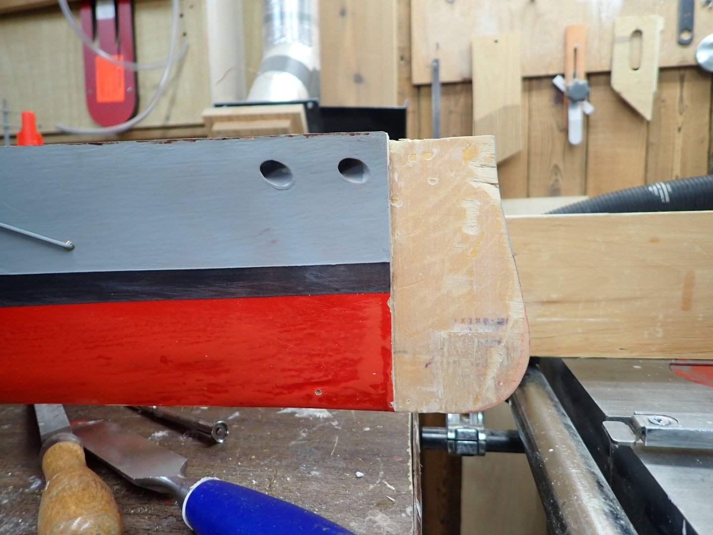
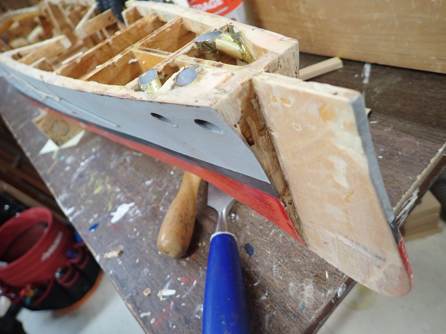
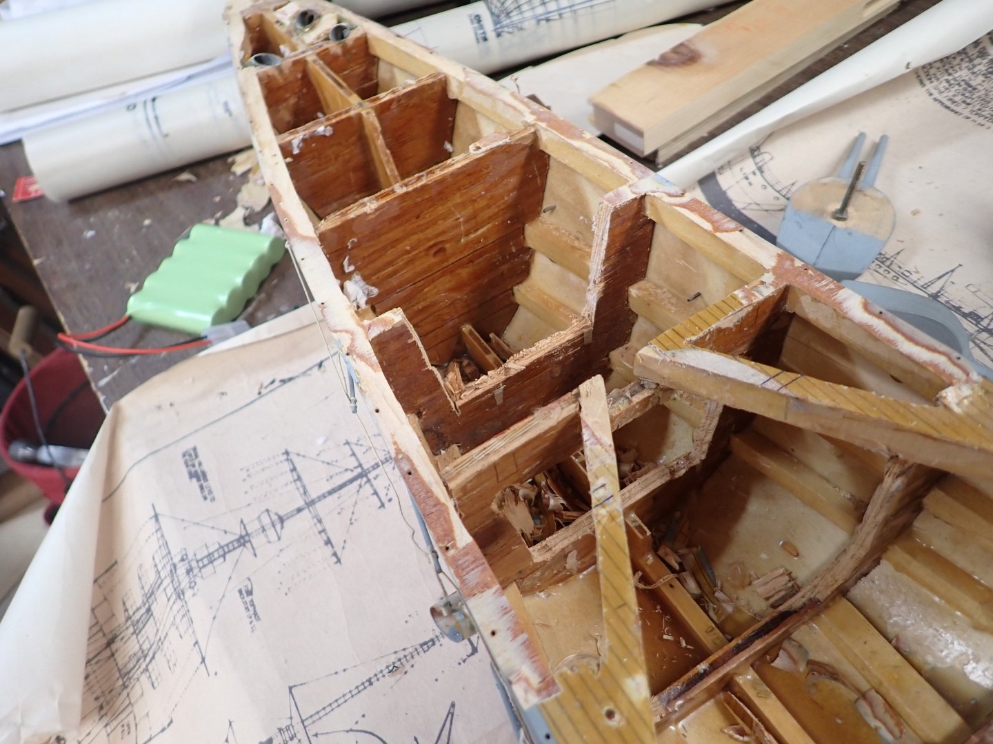
Short update. I needed to patch the bow but while doing so I found it is balsa ahead of the first bulkhead. Delicate choice; I decided to chisel off the balsa and will replace with pine. I did cut the curve of the forefoot into the proper shape . Before I removed the balsa she looked much better than the old squarish forefoot. Also found a dip along about 4" of the port forward sheer while I was trying to align supports for the A/B turret baseplate. Clamped on a thin piece which I will shave. This project has evolved into more work than I expected initially but I'm excited about the final outcome. Still thinking about the smoke unit. We're going away until later in Nov so this log will be quiet for a while.
-
Now that all the ballast is out, the hull weighs next to nothing. I'm guessing 1-1/2 pounds, maybe? Maybe even less?
-
Thanks Patrick for taking the time for a long drive to get it straight from the horse's mouth.
-
George - another magnificent model meeting your exceedingly high standard! Fantastic at this scale, or indeed any scale.
-
Suggestion: 3D print.
-
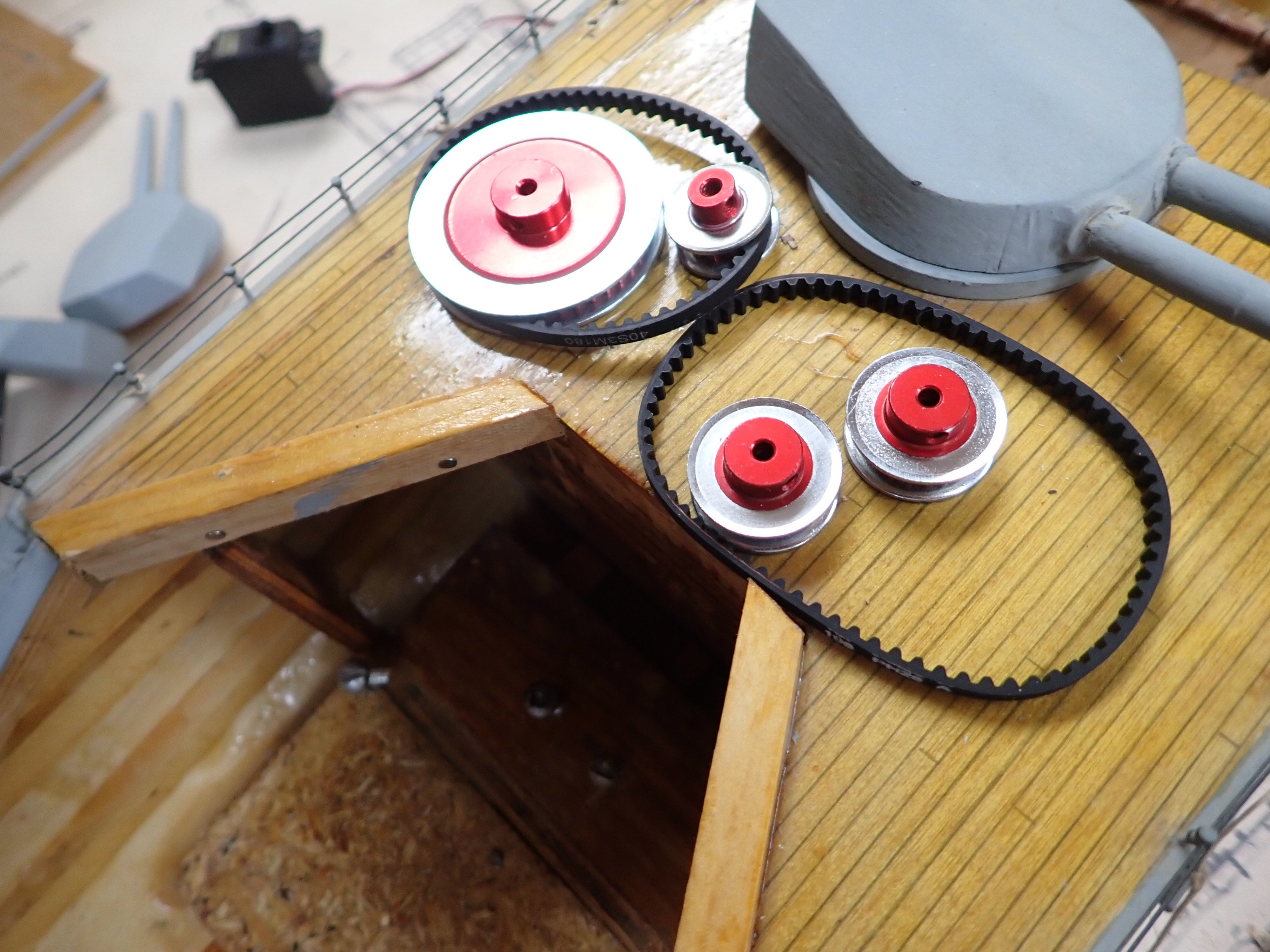
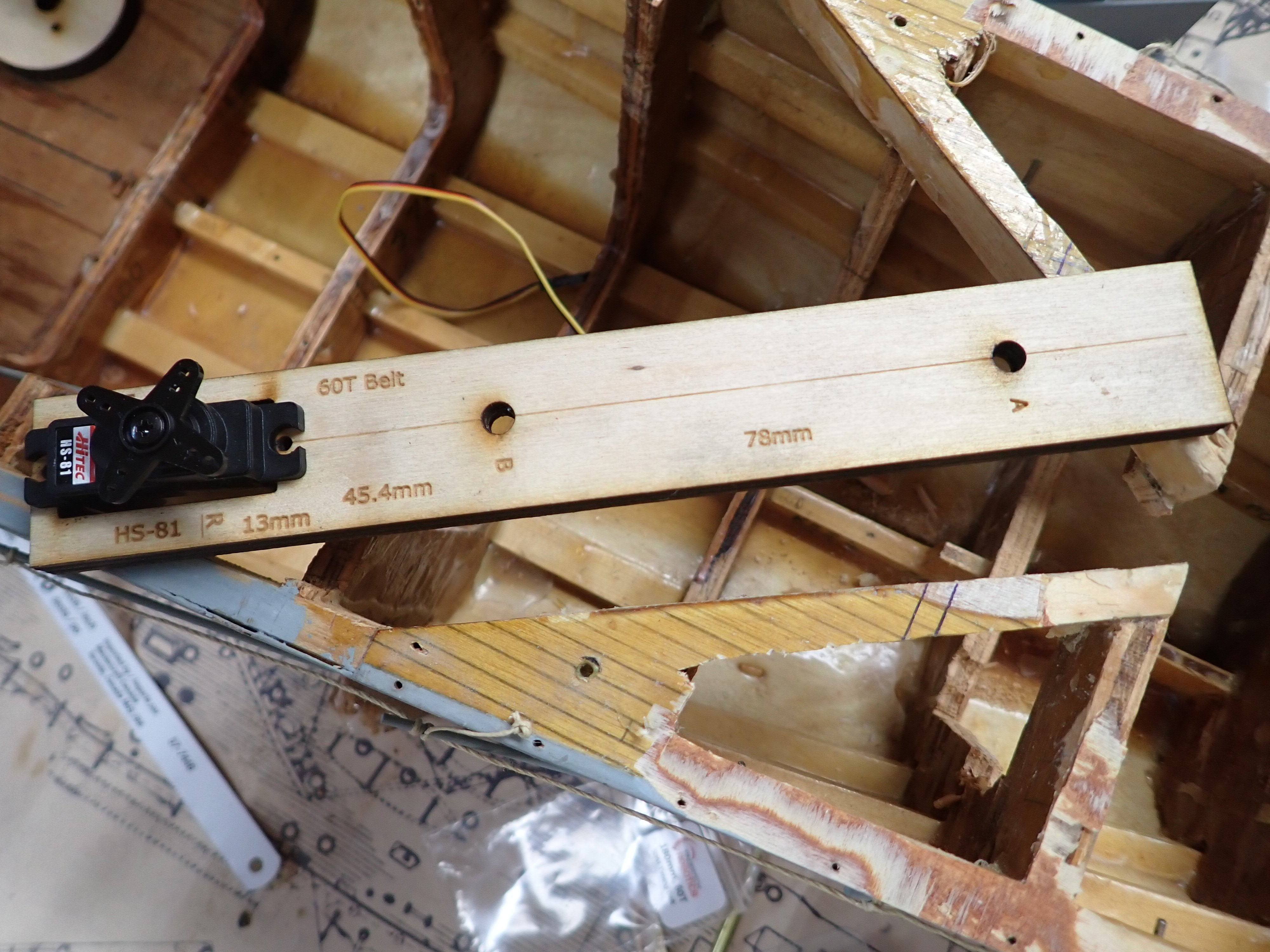
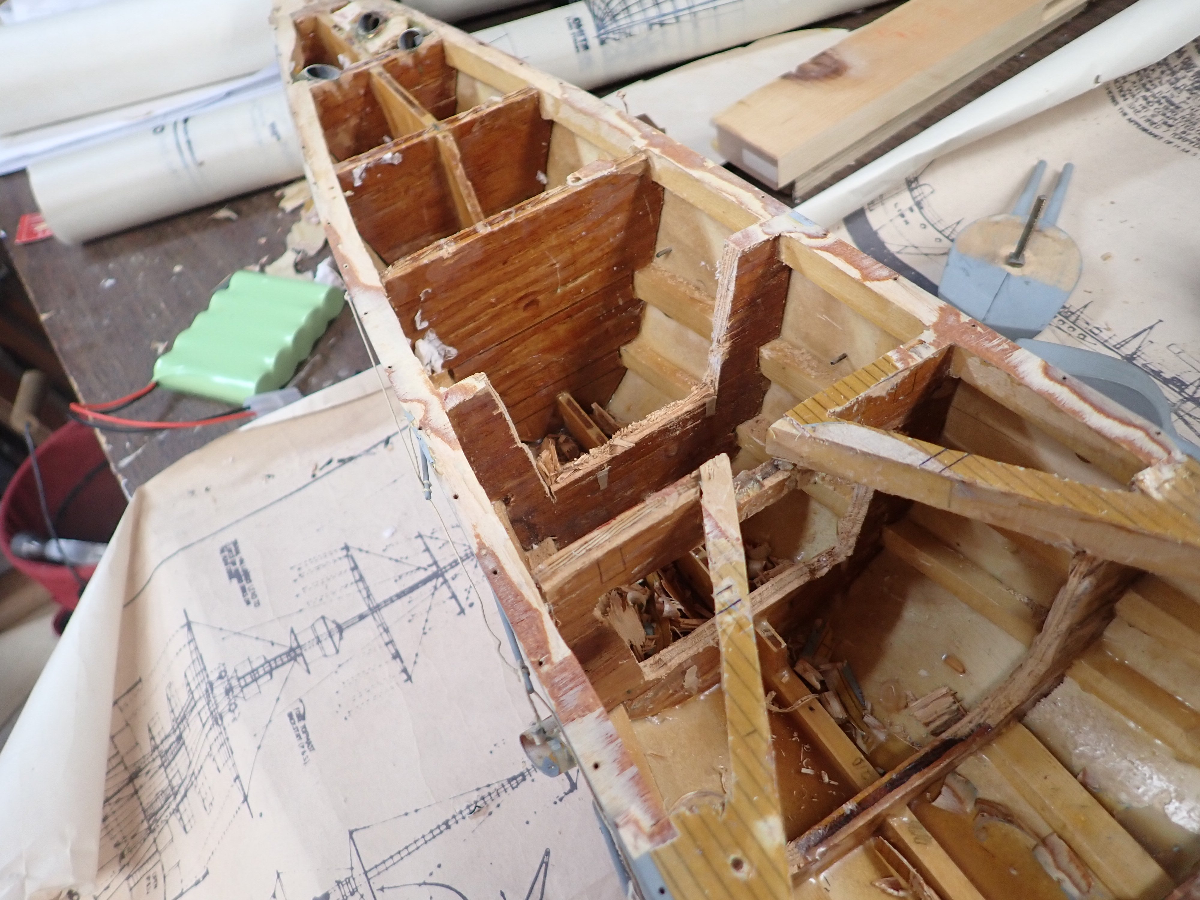
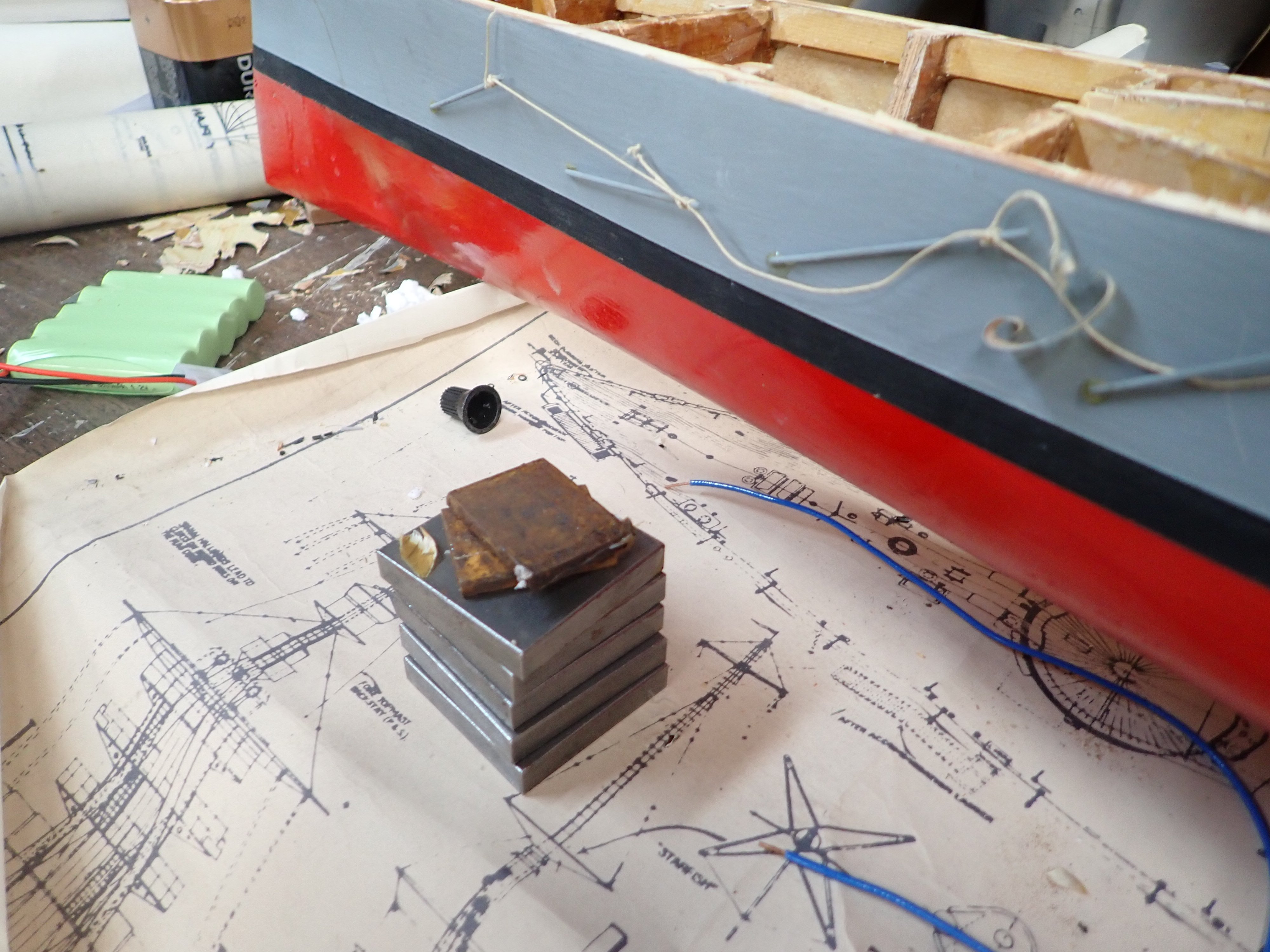
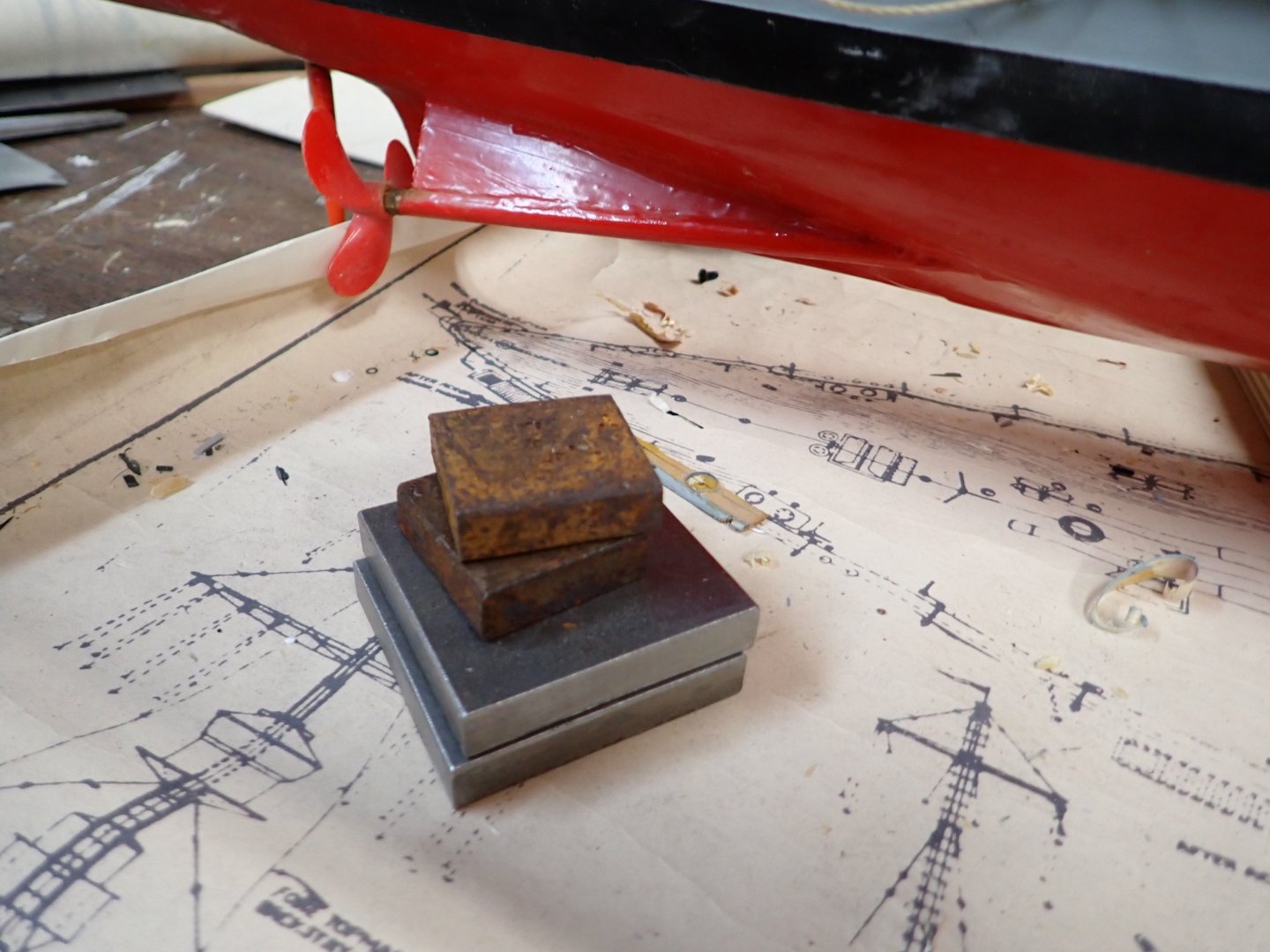
Removed the aft deck to find more ballast and more sytrofoam in the inaccessible aft compartments, and also a time capsule note for posterity...... 😏 Aft compartments, with rudder linkage. Here's how much metal ballast was enclosed aft. Speaking of posterity..... Here are the timing gears and belts involved in pivoting A and B turrets in unison. I laser cut a plywood baseplate to set A and B shafts at the correct centres for the first belt, and also set the micro servo's arm axis at the correct centres for the second belt to B shaft. I hope to assemble and test tomorrow.


-
Nice pics of scenic landscapes. An area I've never been to.
-
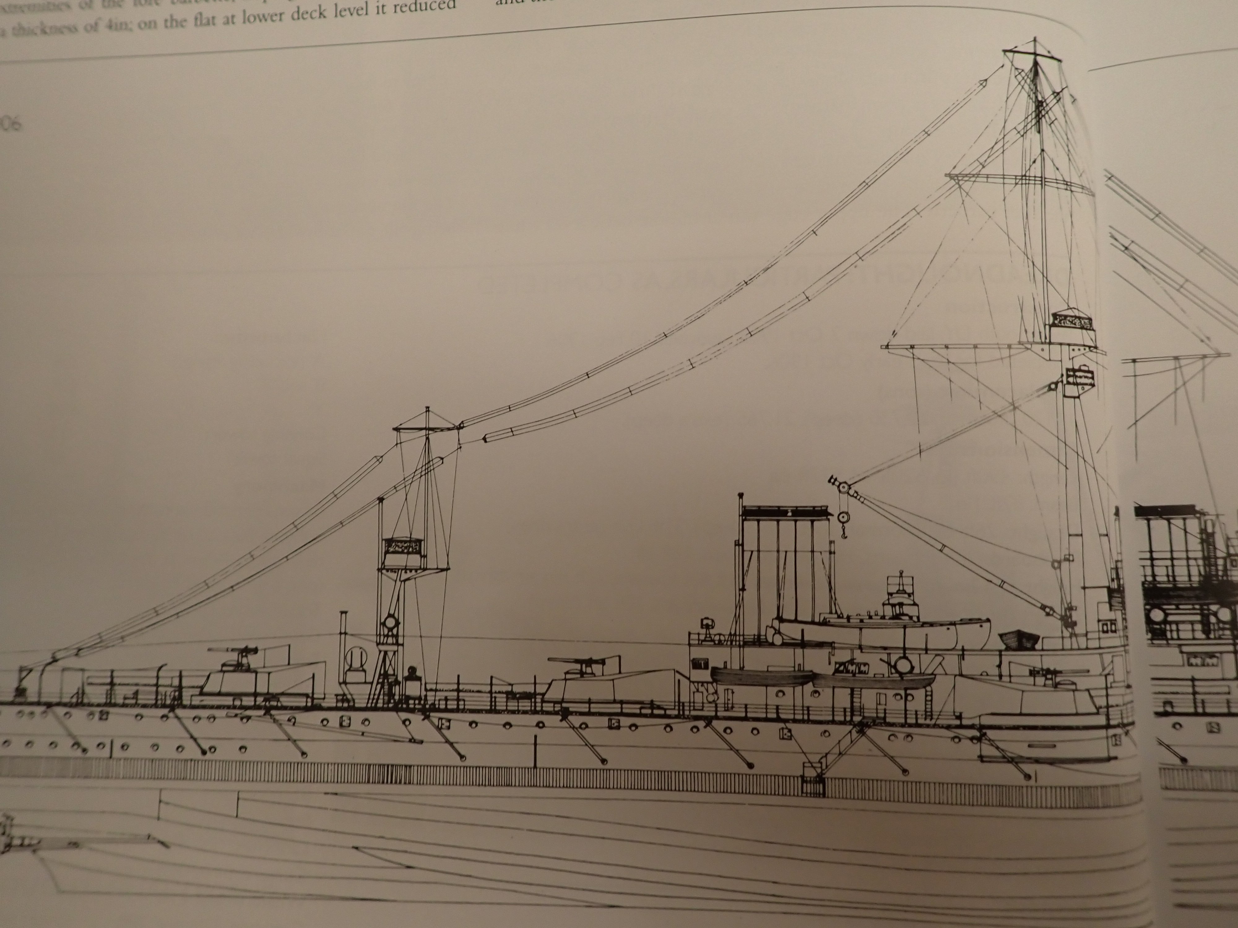
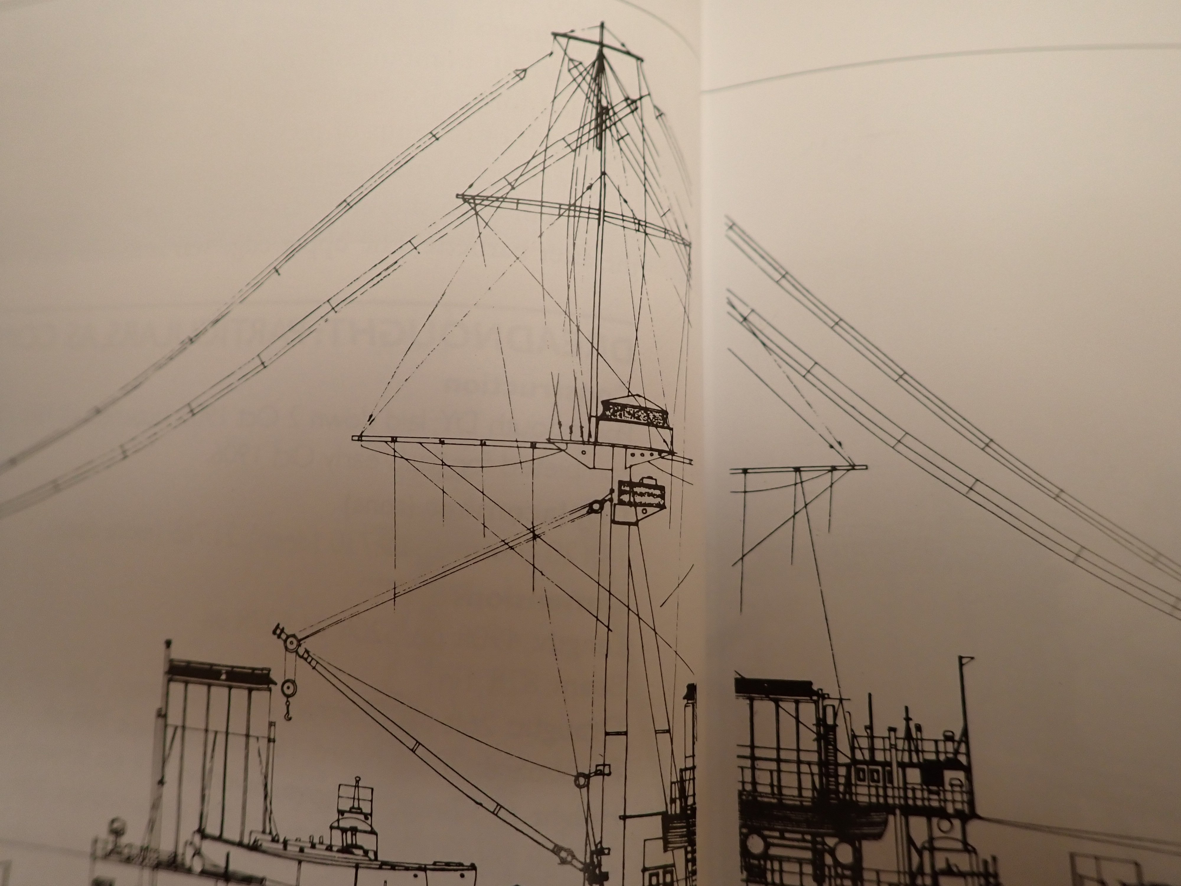
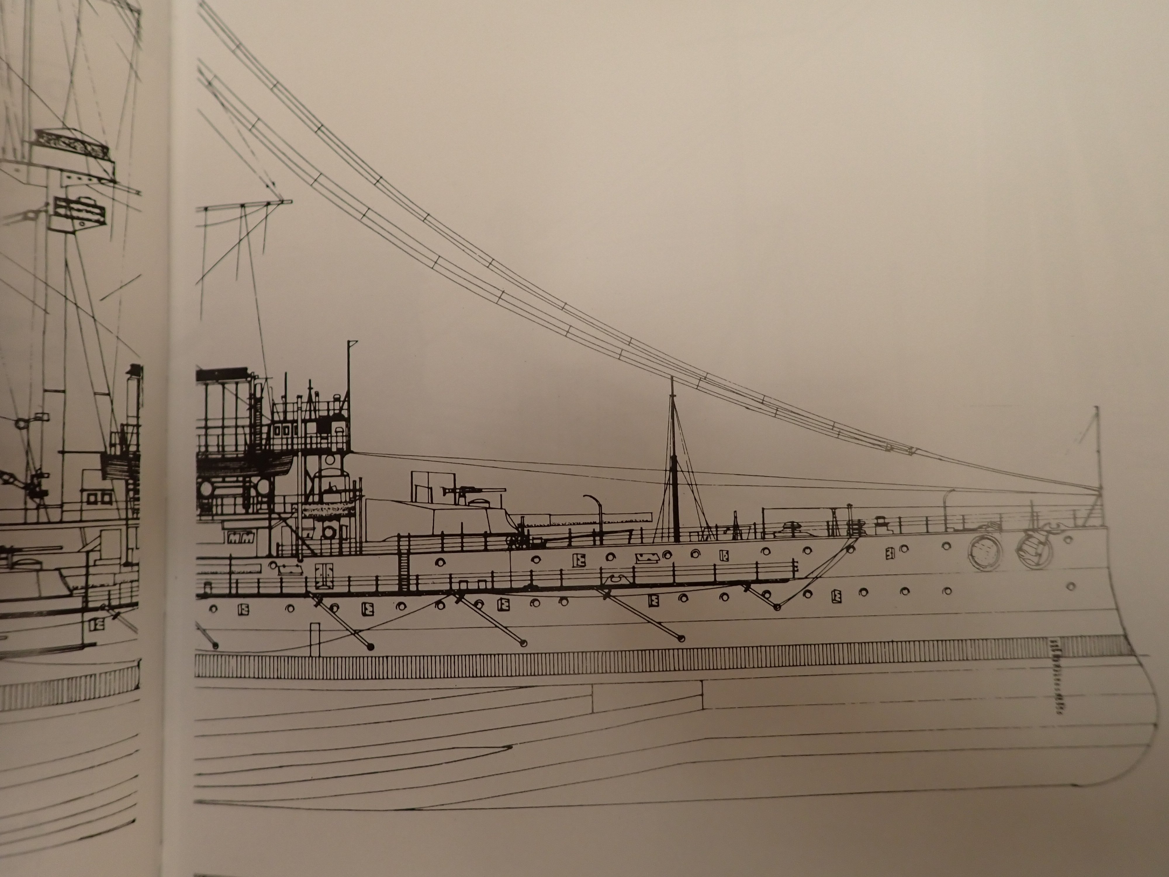
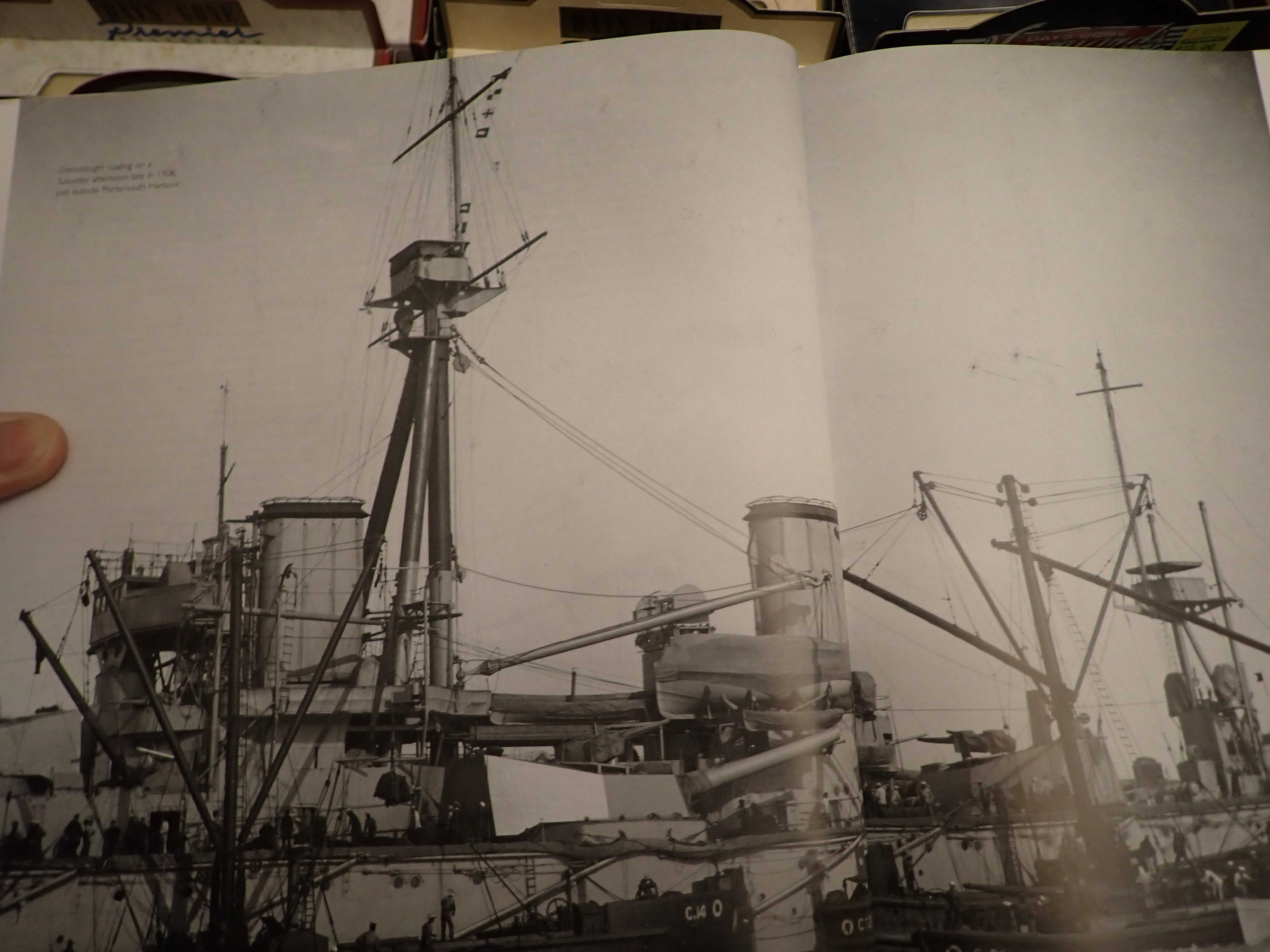
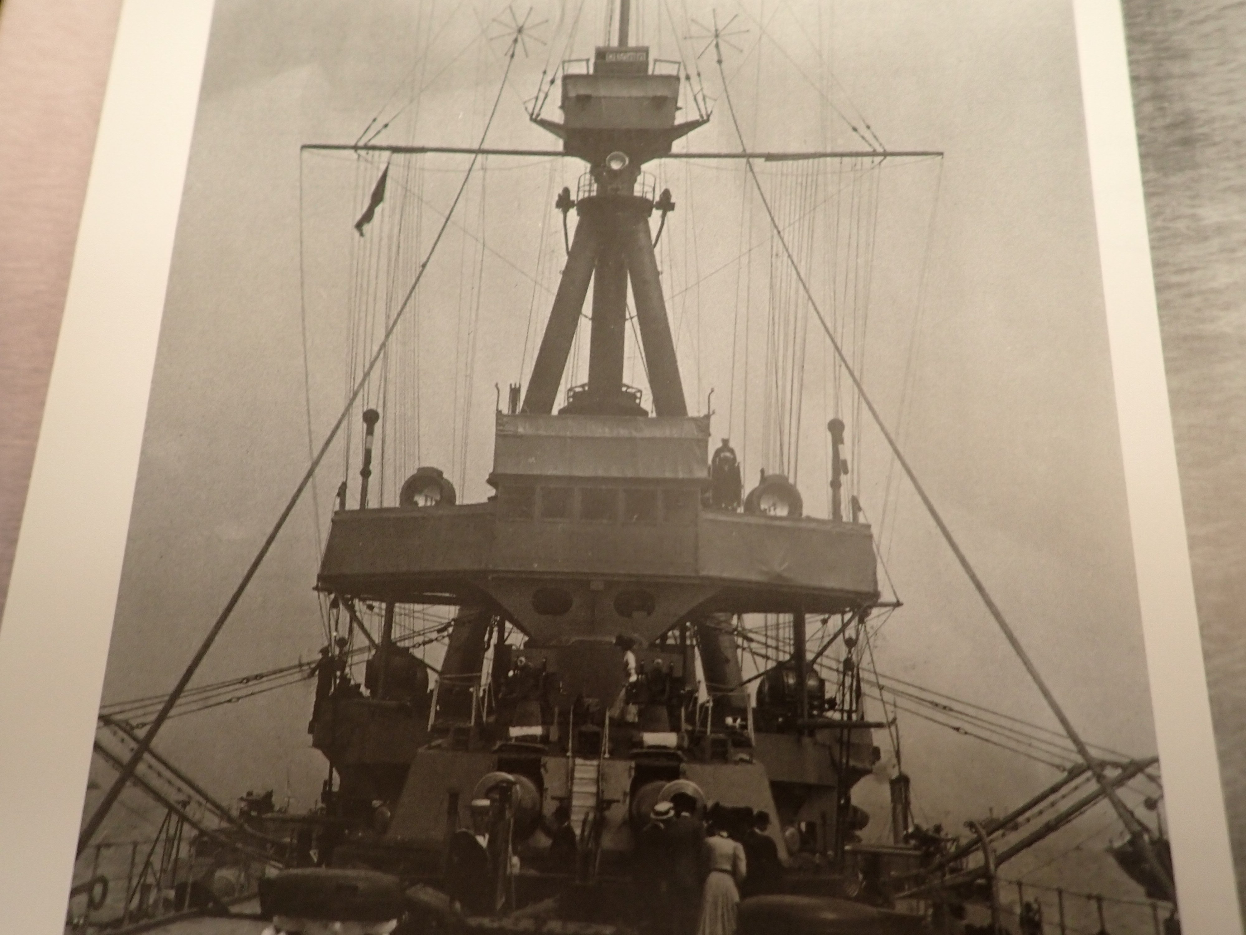
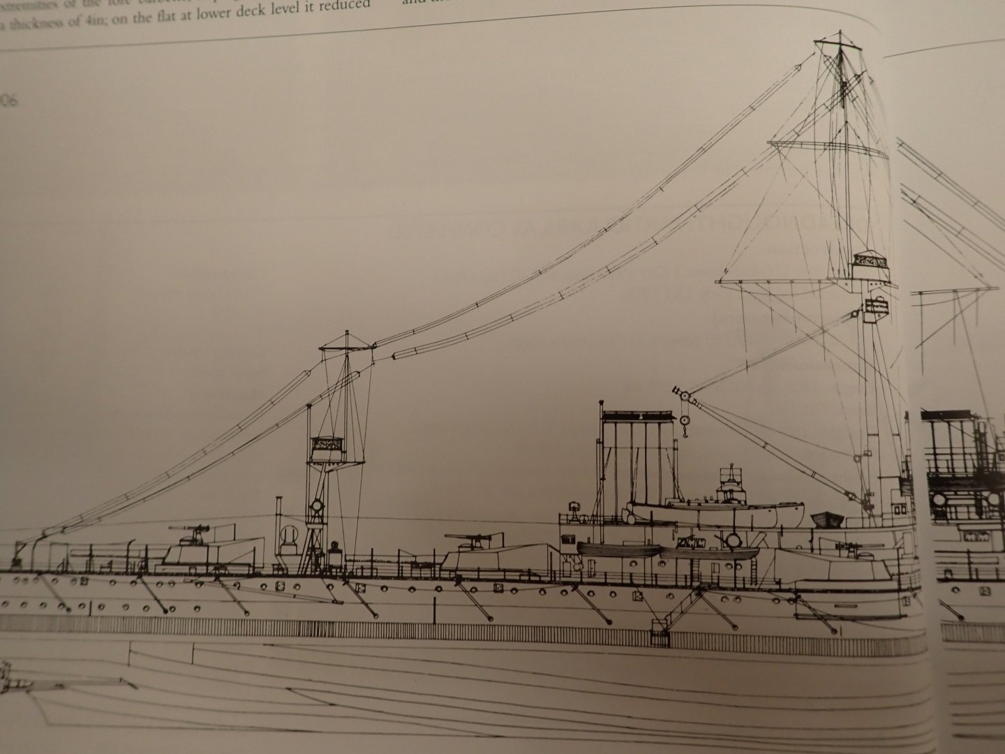
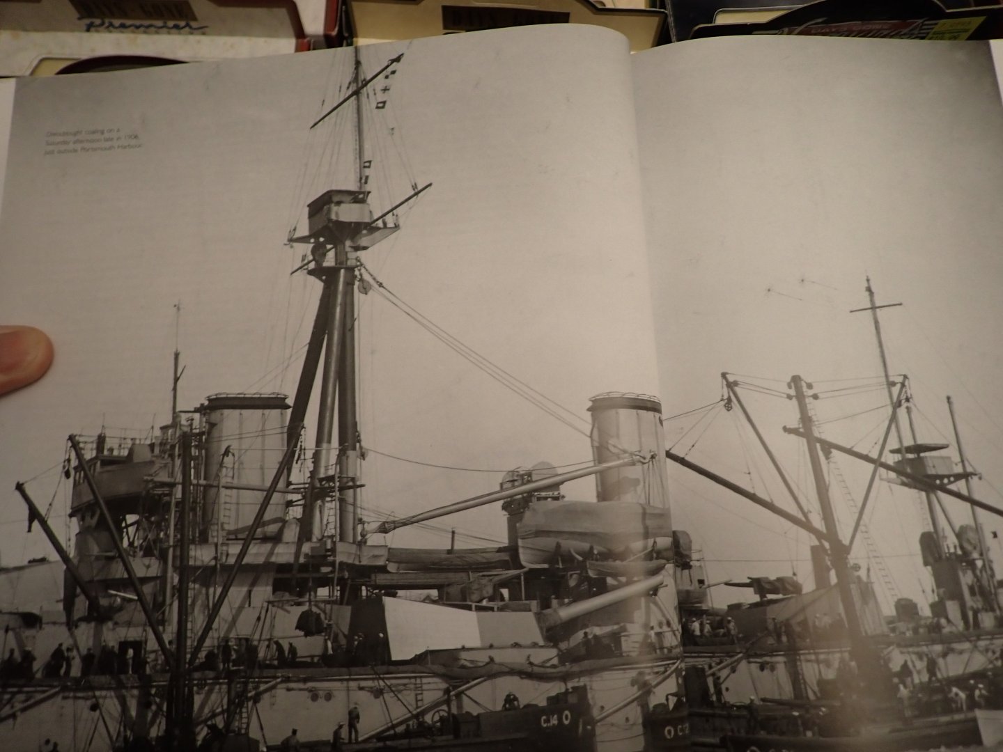
Funny you should ask....I just recently ordered "British Battleships of WWI" by R.A. Burt (I'm re-detailing an RC model of HMS Lion I scratch built in the 70's). This book obviously includes Dreadnought. Here are a few pics which might assist you. In the line drawings of profiles in this book, signal halyards from the yardarms just kind of fade out in mid-air but they all were cleated on the flag deck which at least on Lion is one deck above the shelter deck which is one deck above the weather deck. One of the photos shows a set of signal halyards pretty clearly. If you need a pic of some particular view, let me know and I'll check the other photos. By the way, she looks great! I've never airbrushed a model, I'm such a dinosaur....😭 Ian


-
Hi Glen; FYI usual practice is to hang long weighted lengths of thread for shrouds on the wall to stretch them out. For days. When rigging them, they can then be pulled nice and straight without too much tension.
- 301 replies
-
- 6
-
-
-
- Constitution
- Bluejacket Shipcrafters
- (and 1 more)
-
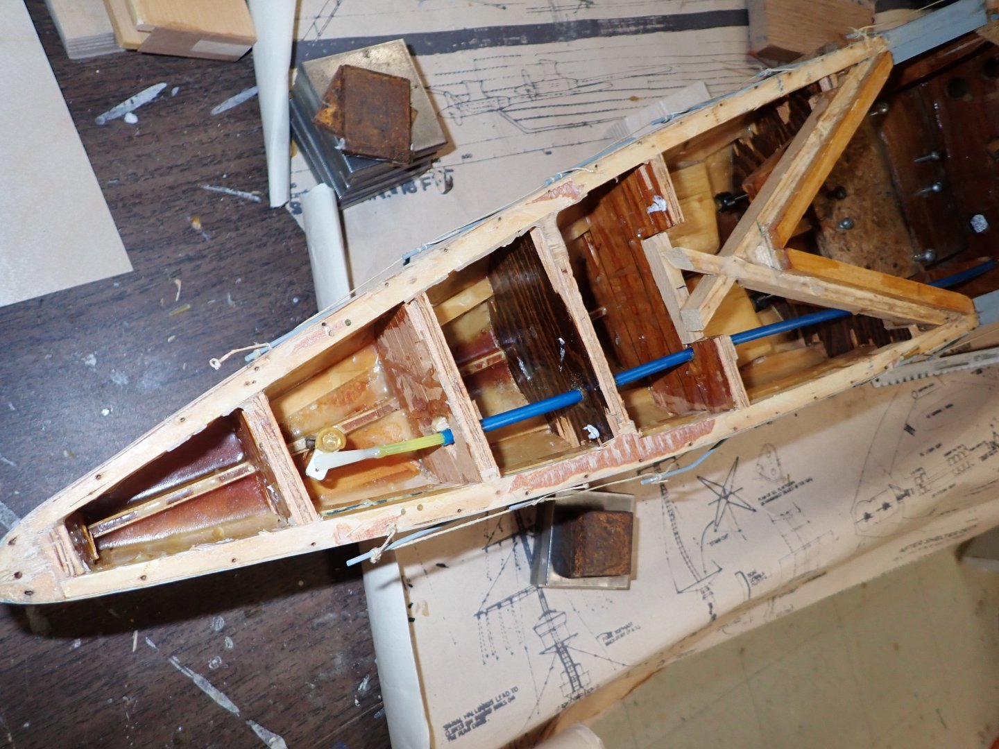
I wanted lots of framing because the skin is only 1/32" plywood. Don't know the weight yet; by the heft of her there's more ballast under the after deck which I haven't torn off yet. 😶
-
Butchered inside the hull for "A" and "B' turret linkage. Hacked out the centre portion of the two bulkheads involved so I can get my hand in up to beneath "A" turret. I'm not sure what the assembly sequence will be vis-a-vis locking the timing gears on their shafts, given that the deck and barbettes must be on before the turrets are added. I'm about to make a plywood "base" which will define the spacing between the brass tube liner shafts for the turrets, and the required servo. I realized that I can reverse the servo's rotation simply by mounting it upside down which also has implications around fixing the gear to the servo arm below the servo body. The good part is I can use the laser cutter to form this plywood part, with shaft pilot holes and servo mounting holes drilled with pinpoint precision so belts/gears will work well. Bulkheads hacked out. Here is all the metal ballast from the bow compartments. It's a considerable weight. I'm not sure what battery I will be using, the 70's gel-cell was itself very heavy yet all this extra metal was needed. I can see I'll need to buy a battery and build a shallow tank in the shop for some flotation tests before the decks go on again. I lubed the two motors for the first time in 40 years. The prop shaft stuffing tubes sound absolutely dry too.

-
I finally unboxed the A1 3D printer. Is it just me, or is it harder to figure stuff out without an included printed manual? Their included "quick start" comprises about eight 3"x2" pages. My first problem was encountered while attempting to screw in 10 machine screws to attach the printer head frame to the base. The six central ones simply would not go in. I took it apart and tried again twice before finally noticing the six threaded holes in the base were covered by very tough transparent tape which of course peeled off in tiny shards. There is absolutely no mention of this in the "quick start". And no apparent reason for the tape, at least to me. I had problems trying to produce a sample print. What do I as a raw beginner know? This is supposed to be a beginner's machine. After plodding my way through getting the printer to bind to my Bambu account and giving it a name for the network, and waiting about an hour for it to do a full self-calibration, I could not get it to notice the filament I pressed into the tube. What is there to know, I thought? Just push the filament into the plastic sleeve until it enters the printing head and stops. Then I tried to get a pre-stored sample design (a little boatie) to print. Nothin' doin'. I had to google to youtube to find out that I have to go through menu screens to find "Load Filament" and press it and then the thing warms up the head and tells you to push the filament in "now" ( and by the way before you do this you have to find the menu locstion to tell it exactly what type of filament you propose to use. It then failed to see the filament and bleeped "retry" several times with me pushing the filament each time. Then it spent about ten minutes doing I don't know what, with the head moving around sometimes touching the base plate and sometimes going over to the head cleaning attachment while I wondered what was wrong. Finally it started the print and came out with a beautiful print in less than 15 minute , which surprised me because it was moving so fast the desk and floor were shaking. It's blindingly fast compared to the library printers. I think I will set the speed to 60% from now on, which is the next option down from 100% which was the default. I find it annoying that I needed to blunder around on youtube to find out such basic info instead of it being provided in the box on just a few sheets of paper. It will be interesting to discover if there was needless delay because of some other menu option I am not aware of, or if the head cleans itself several times before every print. Anyway, the print is beautiful and I'm sure I will get used to printing with time. Next up: Have to figure out Bambu's slicer program. Another thing I have never used. At the library "Makerbot" just does it for you with no manual intervention necessary.
-
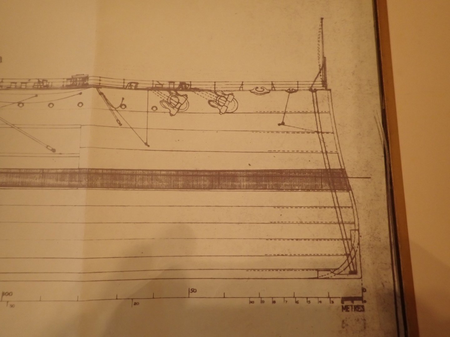
I took another look at my Norman Ough drawings. I can see why the teenage me made the forefoot squarish thinking that's just the way these old ships were, but looking now it seems that there is a gadget placed over the forefoot and clinched in place by lines/chains to the cleats on the foredeck. Some sort of cable cutter ,maybe? Or something to do with paravanes?
-
Looks great Glen! Awaiting with bated breath the insertion video!!
- 185 replies
-
- 8
-
-
- Flying Dutchman
- Black pearl
- (and 2 more)