MEPering
-
Posts
91 -
Joined
-
Last visited
Content Type
Profiles
Forums
Gallery
Events
Everything posted by MEPering
-
Well, I finished my deck, and immediately got thrown into another situation. And then another after another. So Constitution is still on hold. But I got impatient. Ship building, I find, is sort of addictive... Coming from railroading, it surprises me how satisfying it is. But I want my Connie to be as perfect as I can get her, so I have not touched it since my last update. That being said, I was frustrated at not being able to practice modelling, so I went to my local hobby shop and bought Model Expo's "Fair American". That was last March. I finally started it around a month and a half ago, just to try my hand at various tasks that would be required for Constitution. It really didn't occur to me to start a build log on it, but I notice now that there are not many on it. So Constitution is on hold for the moment. The build of "Fair American" is coming soon. Matt
- 117 replies
-
- 5
-

-
- constitution
- model shipways
- (and 1 more)
-
Hi Tom, I did the same on my Constitution build, and it truly makes for a much more stable frame, and I would not want to try and fair without the braces. It took me a couple of days to brace mine, using a pair of calipers to try and get it all exactly spot-on. Looking forward to your progress and will be following. Matt
-
That turning looks 100% better than the brittania castings that come with the kit, Ken. Especially considering that these parts on the prototype are bright finished wood. The deck looks great too. Matt
-
Actually, Geoff, the rivets go all the way through, but are flush with the back of the bulwark planks. CA or super glue will probably be applied from the back to hold them in position, relying on capillary action to suck the glue in. The problem with this is that it stiffens the plank quite a lot. So heating the plank will be necessary to make it fit after the studs are mounted, and after the fairing has occurred. This may be easier than it appears, since the copper wire conducts heat very quickly. Brass wire would do so almost as quickly. This being said, I think that the bulwarks should be done on the interior of the deck before the external planking should go on. This allows for mistakes to be removed more easily. Of course, this means exterior planking, at least for the bulwarks, needs to be perfect. Due to less curvature in the outer planking, I think this should be the better approach. I wish I could get to the ship to test some of these things, but it has been so busy this summer, I can't seem to do this at this time. Building this deck off the house is taking all of my time at the moment, and probably will through the first of July... Possibly longer. But this gives me time to think, so it is not all bad. As a first ship for me, I think I should be spending about 10 hours of thinking for 1 hour of building. The building I miss though, and I shall return to it as soon as I can get to it. Matt
- 117 replies
-
- 4
-
-
- constitution
- model shipways
- (and 1 more)
-
Thanks for the responses, CaptainSteve, EJ. and Jon. I don't think there is a wrong answer here. I do think that I am going to attempt the bolts/rivets after thinking about it more though. What made me wonder about it was that I wanted to fair the inner bulwarks, which if I had the bolts/rivets installed, would not be possible. So I had to come up with a solution. I think I have now. So I will be installing them. There were basically 4 ways to approach this problem. The first option was to forget about emulating the feature, but it is prominent on the ship, so I decided against it unless I can't make my method work. The second option was to just fit the planks with the fixtures, and not worry about fairing them. This is an unacceptable solution to me, since at this scale, with the variance in the planks I have, things would have looked too much out of scale. The third way to do this is to install the planks, fair them, and then install the fixtures. This is a viable approach, but it is labor intensive, and could lead to excessive variance in fixture height. Well, except for the third approach, these are not viable from a modelling perspective. However, the fourth solution seems to be the best. This is, to mount the planks with an easily dissolved adhesive, fair them, then dismount them one at a time, attach the fixtures, and remount them permanently. This seem like a lot of work, and I am sure it will be. But this seems to me to be the best way to handle this problem. If anyone can suggest a better way, I would love to hear it. The fixtures have to be very subtle, due to scale. Tiny dots of glue I have used on plastic models, but I have never been satisfied with the irregularity this method has given me. I will do a test on this method, and post it soon. Matt
- 117 replies
-
- 5
-
-
- constitution
- model shipways
- (and 1 more)
-
Thanks, David. I am noticing that the fairing is not to bad here as well, but having time to get a bit of it done is. Since we are both doing the MS version, I wouldn't expect it to be that different. However, for me, to find time to work on it is getting to be a challenge. I mentioned in and earlier post that I am busy with a deck on the rear of our home, and that is preventing me from shipyard work at the moment. But this too shall pass and I will get back to it. But that doesn't mean I don't have time to think about the ship. I have decided that if I am going to do the simulated rivets, I need a bit smaller wire. It is currently looking like .010 or perhaps even smaller. This gives rise to another question though... How am I going to make them seen. I feel this is an important detail, but it must be close to scale. To exaggerate a fine detail like this will detract from the model instead of making it more realistic. I know it is impossible to make an exact model, but I want to make this as close as I can to the prototype. With that being said, perhaps this detail should not appear on the model. I have seen others who have included it, and I applaud them for such a titanic effort, bit is it worth it? I know it is going to bother me if I don't include it, but I also know that most people won't notice if I do include it. So the quandary continues. I am still not sure. When we are considering a projection of 1/2" at most from the bulwark on the prototype, it becomes very hard to justify the inclusion of such a detail. So what do you all think? Is it important, or should it be ignored? I shall await responses. Matt
- 117 replies
-
- 2
-
-
- constitution
- model shipways
- (and 1 more)
-
Fairing is coming along slowly, as the deck off the back of our house is taking priority, but I almost have the starboard side done. I don't have pics of it, but it is pretty standard stuff, but the crappy luane plywood that the bulkheads are faced with are terrible when it comes to adhering to their substrate. I have been impressed by Model Shipways in their craftsmanship so far, but these bulkheads are crap as far as the faces. Why even face them, when they aren't even seen anyway? Maybe they got a deal on this cheap stuff. I don't mean to sound like I am bashing Model Shipways, but it is what it is. It is a quality kit. Perhaps my technique should be modified to reinforce the bulkheads with CA. But that makes it a bit tougher to fair also. I will not be using CA to attach the planking, as I prefer a PVA for this. I knew a man once who did use CA to attach a quarter to his front steps, just to see how many bent over to pick it up. This was right after CA came out, and he did have some stories to tell about it. A quarter was worth a lot more back then. Anyway... Fairing continues on the starboard side, and hopefully I will be planking in a couple of weeks. Matt
- 117 replies
-
- 3
-
-
- constitution
- model shipways
- (and 1 more)
-
Elijah, Mikiek is giving very good advice there. You should decide which side is going to be prominently displayed first, and use the other for experimentation/first build stuff. Since I am also doing a first build, I decided my port side would be the most prominent, since the place I intend to display it shows it off better like that. So I am doing most things on the starboard side first. But this advice also needs to be taken with a grain of salt, because planking should be done on both sides equally, from my understanding. This is probably less important with a solid hull like you have, but with a POB or POF planking, it is important, I think. Like Bill and EJ said, the first plank is most important to get right. Of course you can correct for it later, but that just makes for more work that really isn't necessary if you just get that first one right. After that, make sure your wood is dry after you bend it before mounting it to the ship. It is amazing how much wood can swell when thoroughly wetted. Or you can use strictly a heat bending method, which insures the wood is dry, but this is a more delicate process and you have to be careful not to scorch the wood. This is my preferred method, but wetting is also a good method, considering that the planks are very thin, and don't take much time in the water to saturate. Matt
- 701 replies
-
- 4
-
-
- phantom
- model shipways
- (and 1 more)
-
Yes, Ken. Thanks. Corrected. Matt
-
Sorry to hear of your loss, Pat. Back in the '70s I was building the 1/96 version, but never got it quite totally completed, due to an accident as well. So I feel your pain. I think you will be happier working with wood anyway... Loosing a piece of wood just means you need to remake it. Loosing a casting is the same, but much more complicated if you can't order a replacement from the supplier. Also, if you use the right adhesives in wood, some things are reversible. Plastic is not usually so forgiving. I will be looking forward to seeing your build log of the Lady Nelson. I have heard it is a great starter kit. And having the room is more important than you might think. I have one bench that I have to use for all of my work. I build 18th century firearm reproductions for a living, and when I want to work on my ship, all of that has to be set aside and it gets to be a real headache. Having a dedicated space is not just a convenience... It is more like a must if you want to work efficiently. My bench is only 3' x 7', so there is only space for a single project at a time. When I was a kid, I used the kitchen table for modelling, so I spent as much time cleaning up as modelling... lol. I will look for that new log of yours. Matt
- 32 replies
-
- 2
-
-
- constitution
- revell
- (and 1 more)
-
Looks like excellent work, Ken. Are you also going to be using 3/64th" planking instead of 1/16th" to adjust for the 1/64th" in the plywood carrier? As Jon pointed out, there would be 1/64th" difference if you were going with the original planking. If not, I don't see how waterways and gun ports would align properly either. Matt
-
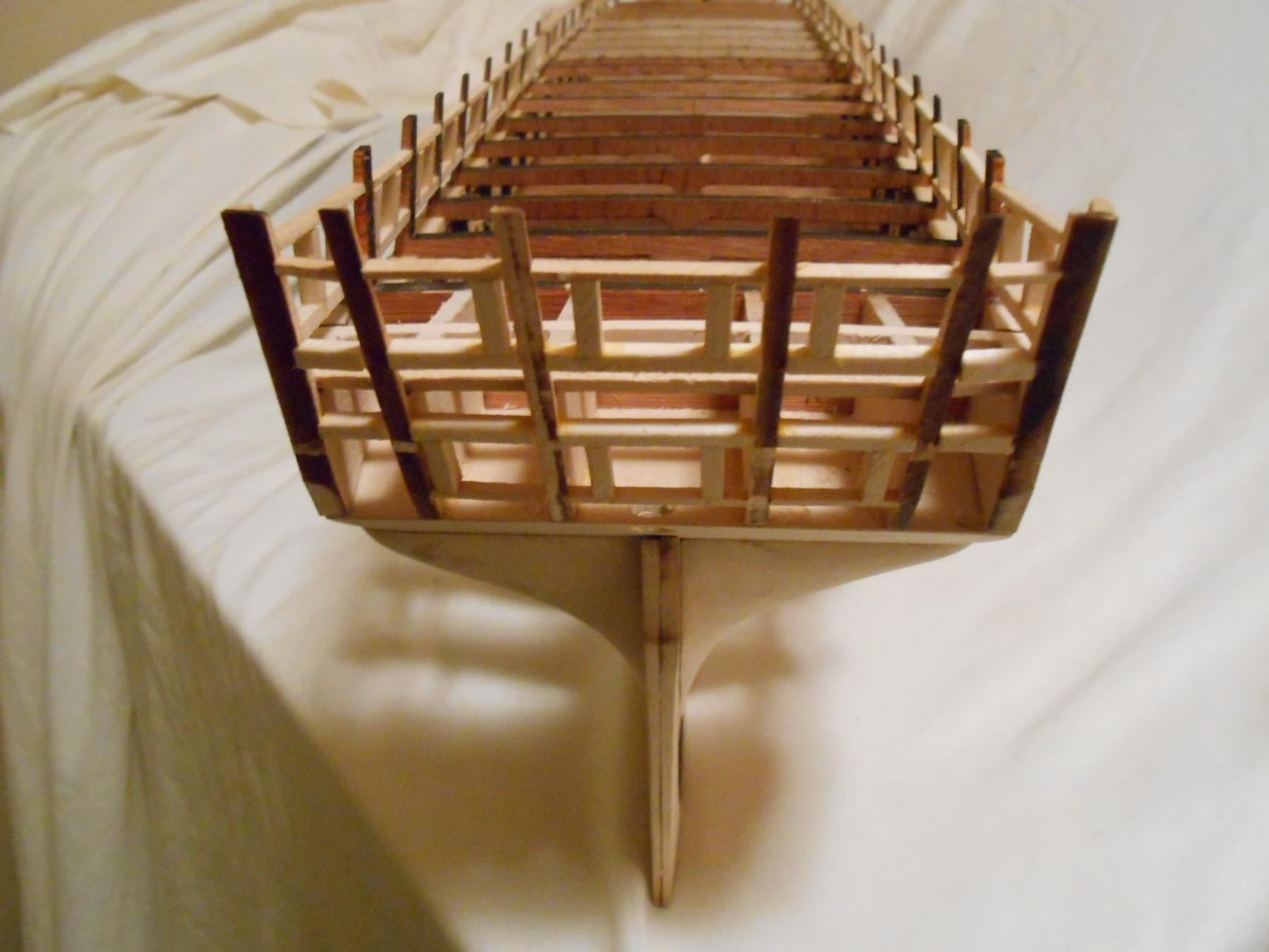
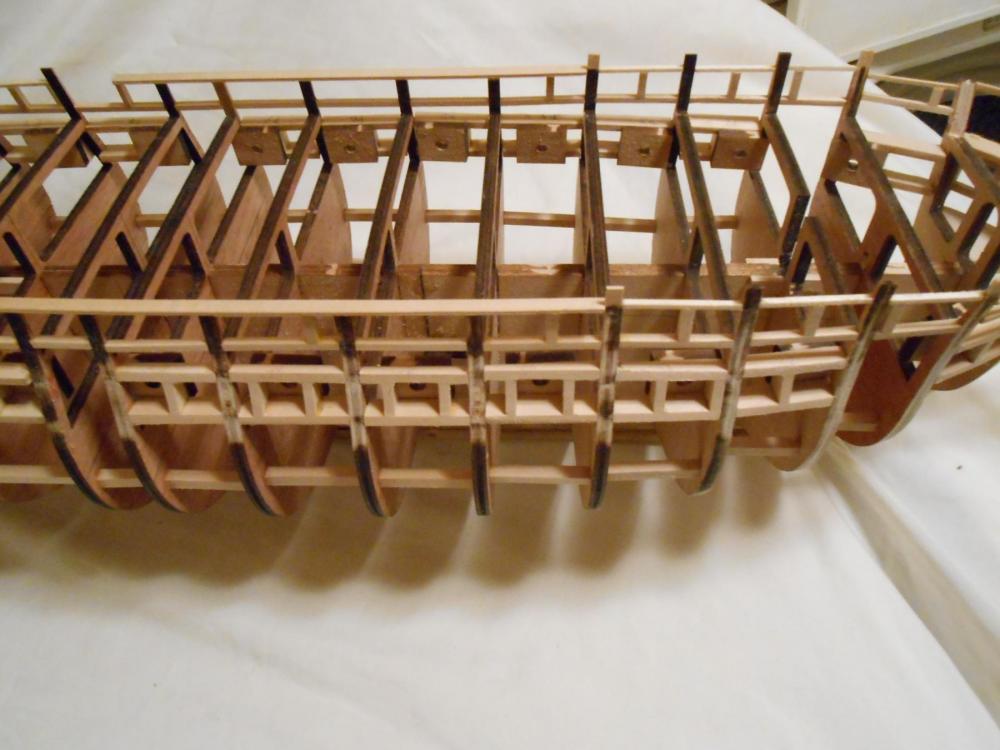
It has been a few days since my last update, but my Admiral sprung on me that she wants a deck built on the bacl of the house, 12' x 30", and she wants it by the 4th of July. Since I am a one-man-shop, this leaves little time for shipyard work. But I did get just a little time tonight to check some things as I was beginning fairing. I made a mistake. My gun deck gun ports are not in the correct position. The are very close, but they are still off. This is a mistake, but it is not major, since I intended on showing the ship with ports closed in most positions anyway. The way I positioned the ports was to use a 1/4" spacer to make them even with the top of the gun deck's bottom. This did not work, since there is variance in how the laser cut bulkheads are cut. Perhaps if I had faired the gun deck first, then this would have worked. But I didn't. In hindsight, I should not have assembled the gun port frames off of the ship. Or perhaps I should have done it differently. But if I were to do it again, I would assemble them on the ship, and then fit the laser cut backs to them. This would have been much more accurate. Had I done it in this manner, this mistake would have been totally avoided. You should be able to see the variance in the picture below. So how to solve the problem? Well, it is more simple than it might seem at first. Once the planking is on from the main rail down to those ports, then it is a matter of shimming and filing. As I said, the error is not that much, and since most of my gun ports are going to be closed, this is how I will solve the problem. Now I could also go to an extreme and chop out those ports and rebuild them, but it is really unnecessary. In most cases, this is only 1/32nd variance. If you look carefully at the picture, You should be able to see that. And it is just a few that are off. I just wanted to throw this out there to warn people about using my original method. When a ship sits in port, the ports are often opened to provide ventilation and drying. My ship is in port with sails off for repair, but I am only going to show a few open, so it is not a major fix. Just a warning to you who are starting this ship. Matt
- 117 replies
-
- 7
-
-
- constitution
- model shipways
- (and 1 more)
-
There are a couple of approaches to how glass is handled in modeling. Acetate is common, and can be curved to fit if necessary. But in real life, you rarely see curved glass for glazing. It is seen, but it is not only uncommon, it is rare. Most glazing is done with ordinary flat sheets of glass, cut to fit an arbitrary opening. I have used acetate in most of my models, but after the last couple, have been using microscope cover glass. It is a quartz glass, which is very tough for its intended purpose and is highly reflective, and it is excellent as far as light transmission goes. I have a couple HO model cars I have used it in, and I am very happy with it. On the downside, it is very fragile and difficult to work with. I use a piece of smooth marble tile when I am working it, and I use a stone to refine the edges. Now if that doesn't deter you from trying it, I think you will be quite impressed with the way it looks. Matt
- 652 replies
-
- 3
-
-
- royal william
- euromodel
- (and 1 more)
-
Sorry the tape didn't work Tom. I have used it with success before, but not on parts this tiny. But I am glad you found a solution. The capstan looks great. My solution for drill wandering is to center punch where I want the drill to center. It had to either be the wandering, or possibly lash in the dividing head. Yours looks fairly new, so I wouldn't suspect this as much. Matt
- 1,348 replies
-
- 1
-
-
- constitution
- model shipways
- (and 1 more)
-
Thanks David and E.J. It is good when you haven't got any experience to get feedback like this from those who do have experience. I did consider the LSS course, but that was before I discovered Model Ship World... lol. Actually, I like the challenge of figuring things out, and Bob's practicum probably would have been too much direct instruction for my liking. I typically learn the most when I have a steep learning-curve to surmount. And yes... It has been a lot of fun so far... more so than I had originally anticipated. And I haven't even gotten to the visible parts of the ship yet. But I think this forum has contributed quite a bit to that too. I don't feel I am stumbling along in the dark as much with the build logs I can read and feedback I get here. Matt
- 117 replies
-
- 4
-
-
- constitution
- model shipways
- (and 1 more)
-
Actually David, you make a good point. My thinking was that it might help strengthen the bulwark extensions, but now that I think about it, the planking should be adequate enough to protect them. And I am pretty certain I am going to be fairly rough on the ship once planking begins. Like the gangway and hammock boards I wouldn't think of mounting before finishing planking and coppering, why should I risk the topgallant rail with it's intricate, fine molding? A most logical suggestion, David, and I think I will take it. Once again, I am finding the instructions should be considered as suggestions rather than instructions. Thanks. Matt
- 117 replies
-
- 3
-
-
- constitution
- model shipways
- (and 1 more)
-
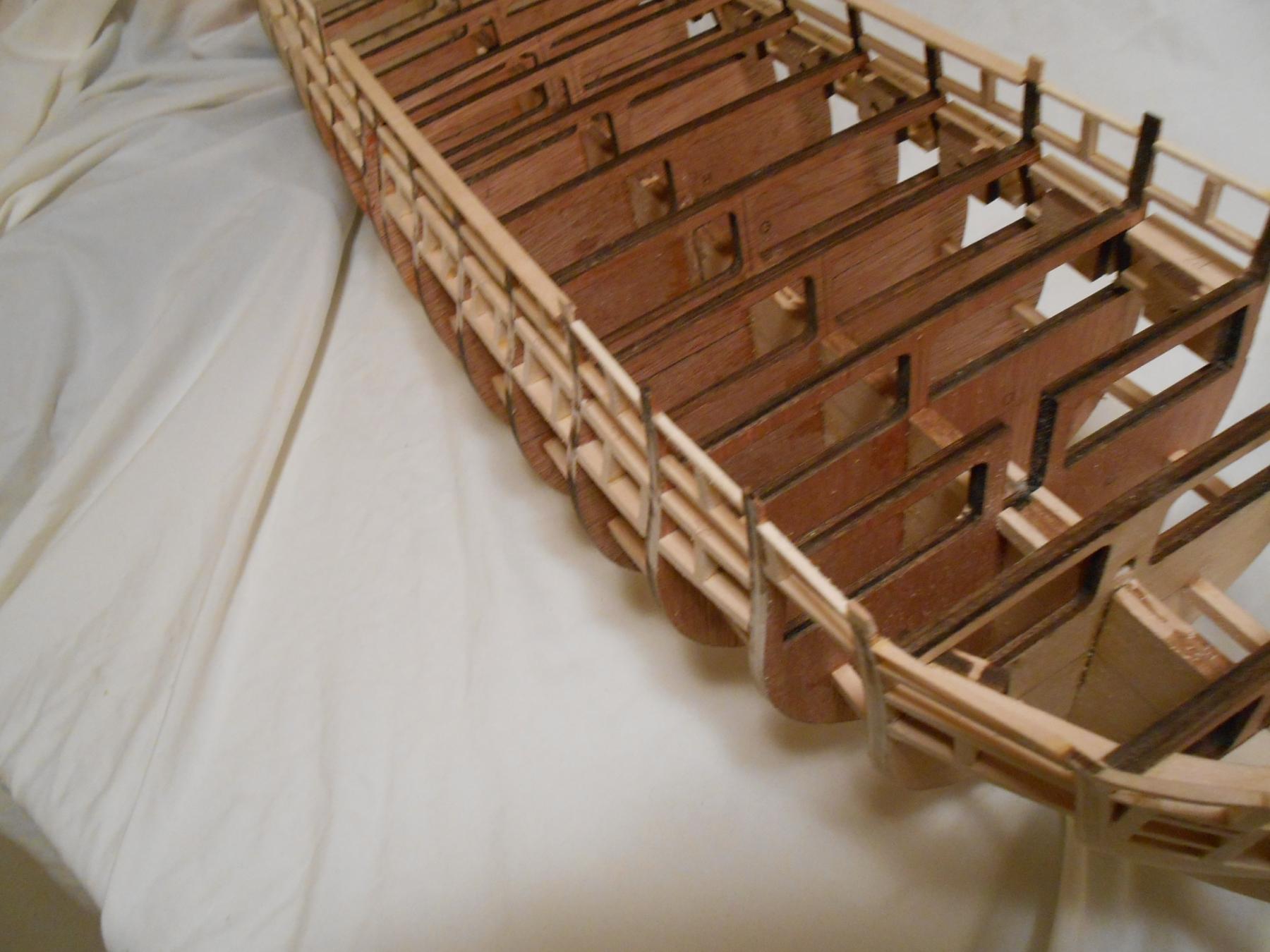
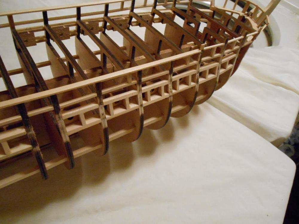
Finally got a little more work done on the ship. I finished up the chase ports. Now to finish up the topgallant rail and waterways and then finish fairing. Planking is quickly approaching. Apologies for the blurry pictures. Matt


- 117 replies
-
- 5
-
-
- constitution
- model shipways
- (and 1 more)
-
Hi Mark. I feel your pain with the weather being so good for the last few days, it doesn't give us much time to model. Lots of yard work and gardening here. I do have a question though... Are those lower transom carvings actually castings? They look super, and with what did you paint them if so? Thanks. Matt
- 652 replies
-
- 3
-
-
- royal william
- euromodel
- (and 1 more)
-
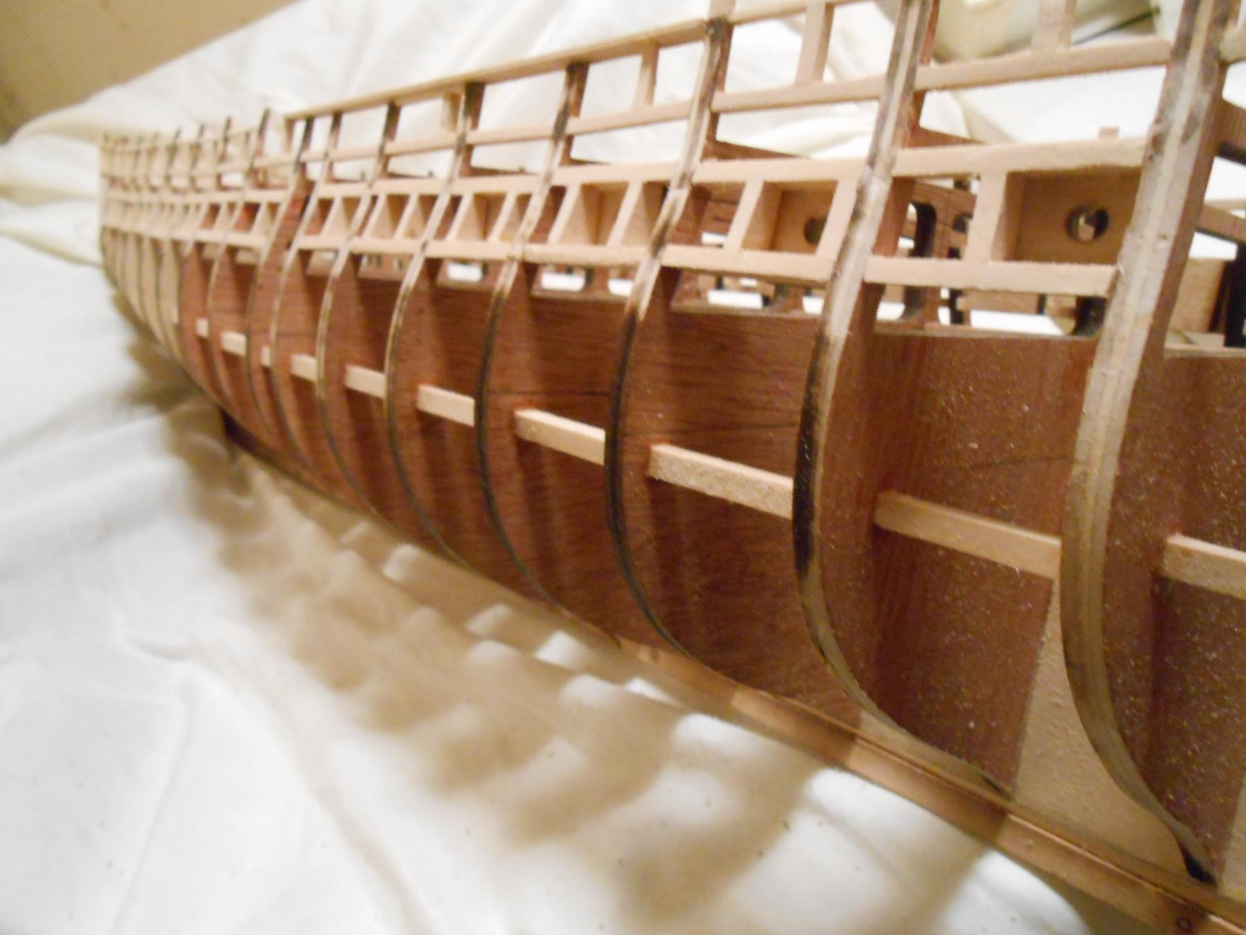
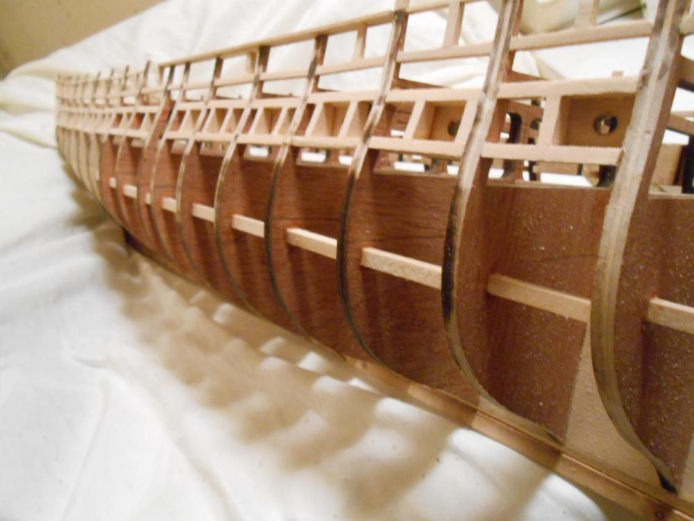
So instead of waste my whole day on gardening, planting and fixing one of the cooling fans on my car that wasn't running, I decided to do something important like starting to fair the hull of the Constitution. I got the front starboard gun, anchor and bridle ports done. I used my Dremel flex-shaft to get it roughly there, and the 150 grit sandpaper backed with wood to finish it. I don't see any reason to go any finer than 150 grit for this process. If someone thinks it needs to be finer, please let me know. My logic for this rougher paper is that the glue I use in the planking process will have more 'tooth' to bite into. Curiously, the instructions totally ignore the fairing process, though I did see a casual reference to it somewhere. Having never faired a ship before, I am a bit in the dark here. I think the only reason for this is to get the bulkheads and other structures mounted to them even, so that the planking lays flat upon them. If this is the case, I think that this practice must have come about back when hide glue was the only available adhesive. Hide glue used to be about the only glue there was for woodworking. I have used true hide glue before, and it is a real headache. It has to be hot, and it stinks. But as far as strength goes, it is very, very strong. It does have several drawbacks though... It won't fill gaps like modern adhesives can. It also doesn't do well in humid environments. I do like hide glue for what it is capable of, but I won't be using it on the Constitution. Modern adhesives are better when things don't fit perfectly. Hide glue also has the advantage that it is easily released... All it takes is some water. And as mentioned before, it is very strong. So here are the photos of the fairing so far. I expect to get the rest of the starboard ports completed tomorrow. It just takes a bit of work, and making sure the sanding board isn't digging in where you don't want it to. This amount of work took me about 45 minutes, so I figure fairing will take me about 5 or 6 hours to complete. Remember, there is inside bulwark fairing to do as well, which is more difficult. I have done a bit of it too, and it is harder to get to with the portion of the main rail installed. Matt

- 117 replies
-
- 9
-
-
- constitution
- model shipways
- (and 1 more)
-
Hi Xken... Thanks for those links. I will probably get those rivets in the future, but on this build, their smallest (.4mm) is just a little too big. However, I have their site bookmarked, since I know of an unrelated application I can use those on, and looks like they have a lot of things I might have a need for. And BTW, nice catch on that bowsprit round-to-square shaping on your build. Had I not seen your post, I might have missed it. Thanks. Thanks, E.J. ... I decided to precut some of these rivets/bolts today, to get an idea as to how long it was going to take. For 100, it took me about 15 minutes, so I didn't think that was to bad. I should be able to do 1000 in a couple hours with practice. And I am guessing at this, but I am starting to think there are close to 5000 of them. My jig for cutting them is just a piece of wood with a hole in it, drilled to the correct depth. Then the wire is inserted and cut flush. Once I get to the point where I am actually doing this ceiling planking, we shall see how it goes, but I think it will look fairly true to the prototype. Matt
- 117 replies
-
- 2
-
-
- constitution
- model shipways
- (and 1 more)
-
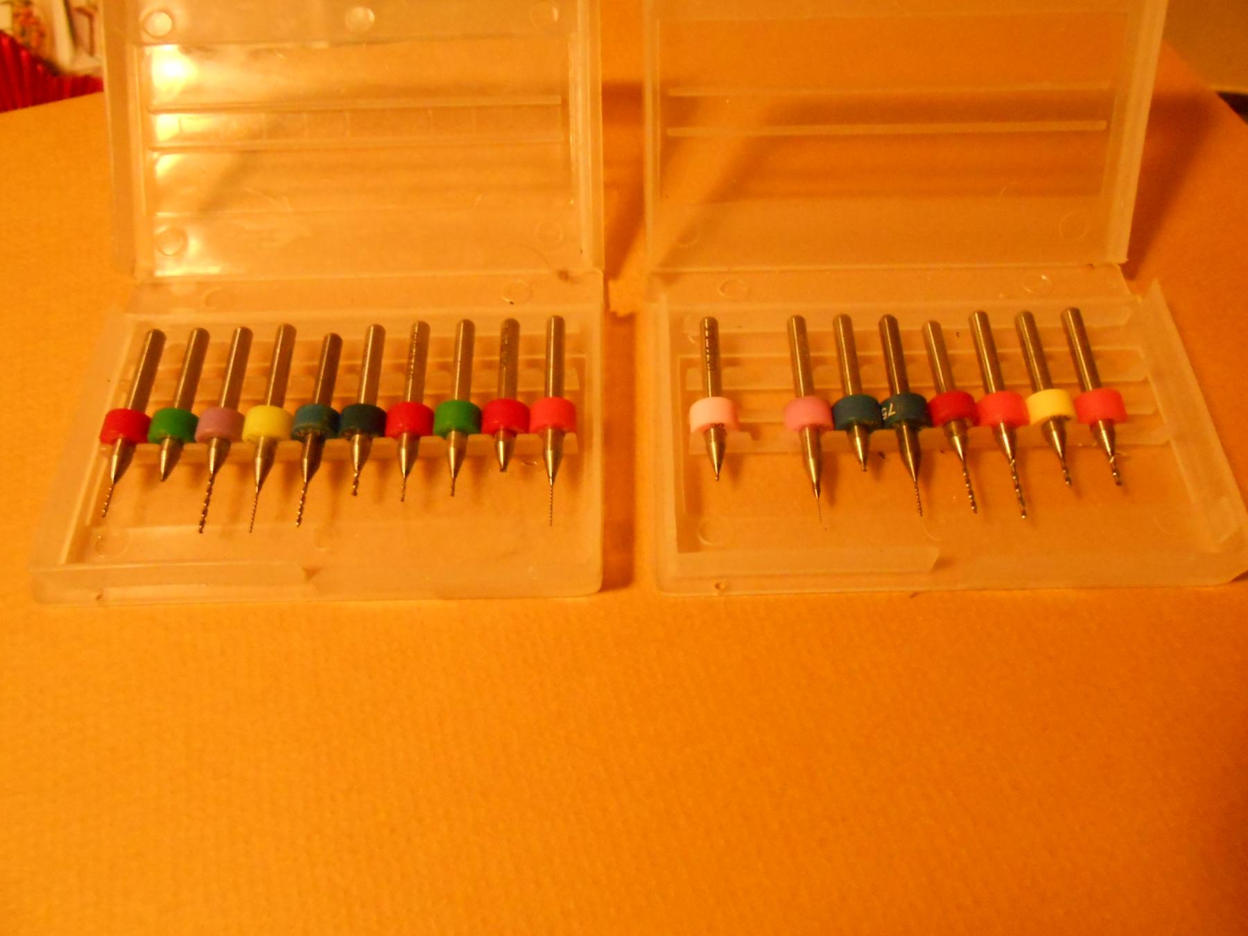
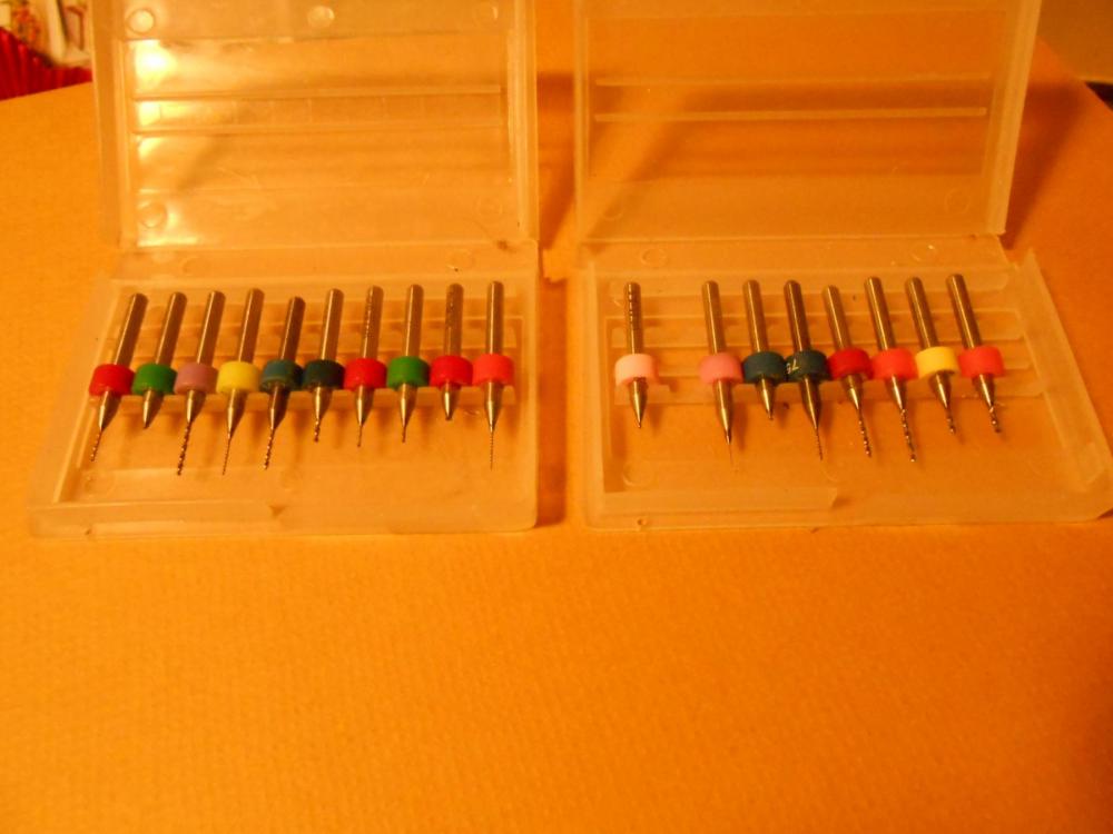
Thanks Tom and yes... Dremel calls it a "workstation", but I call it a drill press. It is Dremel item number 220-01. It is a handy tool. I have used it to drill railroad tie for hand-laid track and wire holes in etched circuit board. The Dremel tool I have mounted in it is just standard, and that includes the chuck. The tiny drill may have made it look like a precision, but it is just off-the-shelf. The drill bit itself is .0145", one of a cheap set I picked up at Harbor Freight Tools years ago. Picture below. Thanks Jon. I have used rivets from Tichy Train Group in the past, and they are fine rivets, but in some cases, I have used N scale rivets on HO models just because they were more to scale for that application. I have also heard good things about the rivet decals that are out, and I can see why they are much more convenient and much, much faster. But the downside is you are stuck with the spacing that the company puts out. The Tichy rivets are individual, and don't suffer this problem, but they are also expensive. With possibly thousands of rivet/bolts on the Constitution, this seemed like a more reasonable solution. I considered using the glue-drop method, but this has never worked well for me, since I have a problem with controlling the size of the drop applied. Some always end up looking too big or too small to me. But I know of guys that have pretty decent success with it. I am afraid though that I am going to run out of brass wire. I only have 8 feet of it, and even though each rivet/bolt is only .060" long, I don't think I have enough, so I had better order some. These little drills actually work quite well, but are easily broken, as you can see. But I have never broken one using it in the drill press... Only when trying to use it freehand or in a pin vise. Matt
- 117 replies
-
- 6
-
-
- constitution
- model shipways
- (and 1 more)
-
CaptainSteve, this is going to take a long time once I get to it. At least a month instead of 1 week as I had predicted. But I am not in a race, and this is an important detail to me. I am going to try and complete it, however it is a lot of work, and I am leary of whether it is going to be worth it. Looking at some of the beautiful models that are here, it is obvious that this is not a necessary detail. David Lester's model doesn't have this detail, and it is still beautiful. Modeling is a fun thing... Some of us see details that we find important, and other are looking at other things that they find much more important. When I model something, I want it as close to the original as I can possibly get, but that doesn't mean every tiny detail. My bolts/rivets are not spaced like they are on the real ship, but they give the impression of what they are. That is what modeling is. I know my bolts/rivets are to tall to be true, but if I made them much closer, nobody would see them other than me. This is a balance we all have to walk between what is real and what is the model. It is true that we have little choice how we must make these adjustments, and it is important how we think through these things. When I made those test pieces, I knew they were too long, and they will be maybe a 64th shorter in the final. Matt
- 117 replies
-
- 5
-
-
- constitution
- model shipways
- (and 1 more)
-
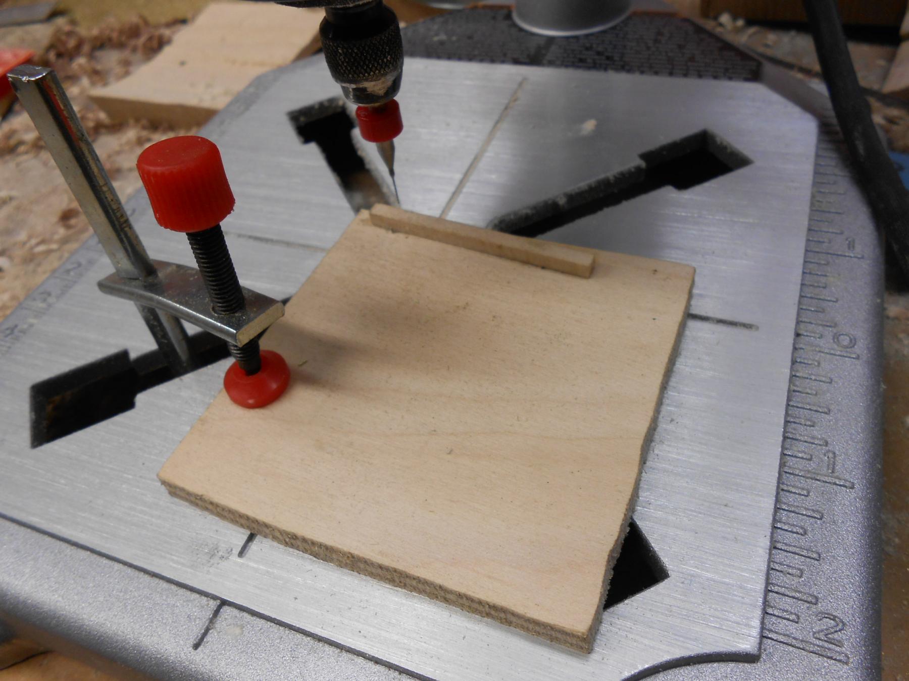
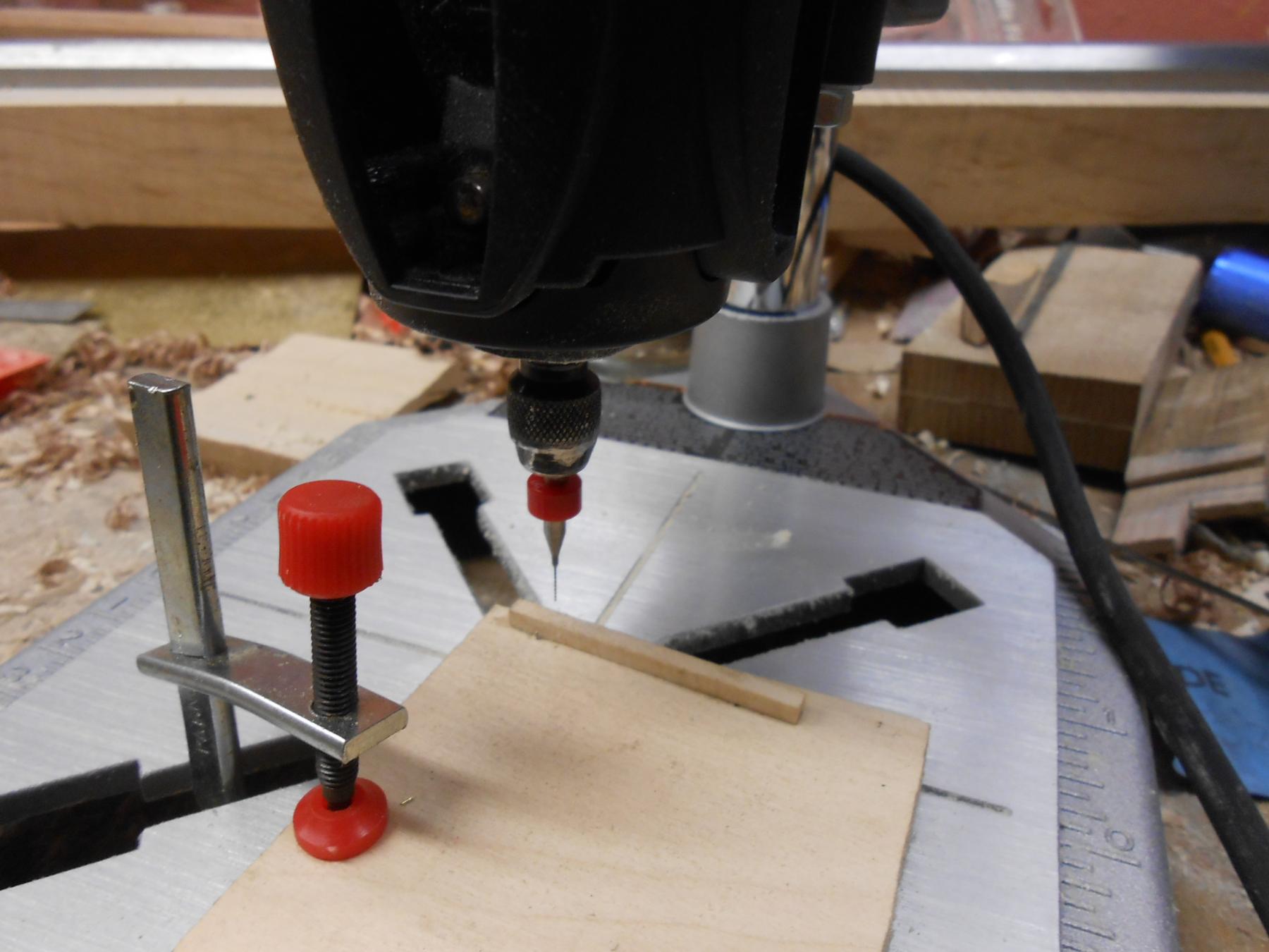
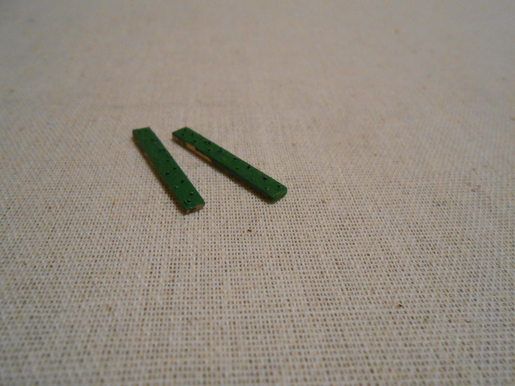
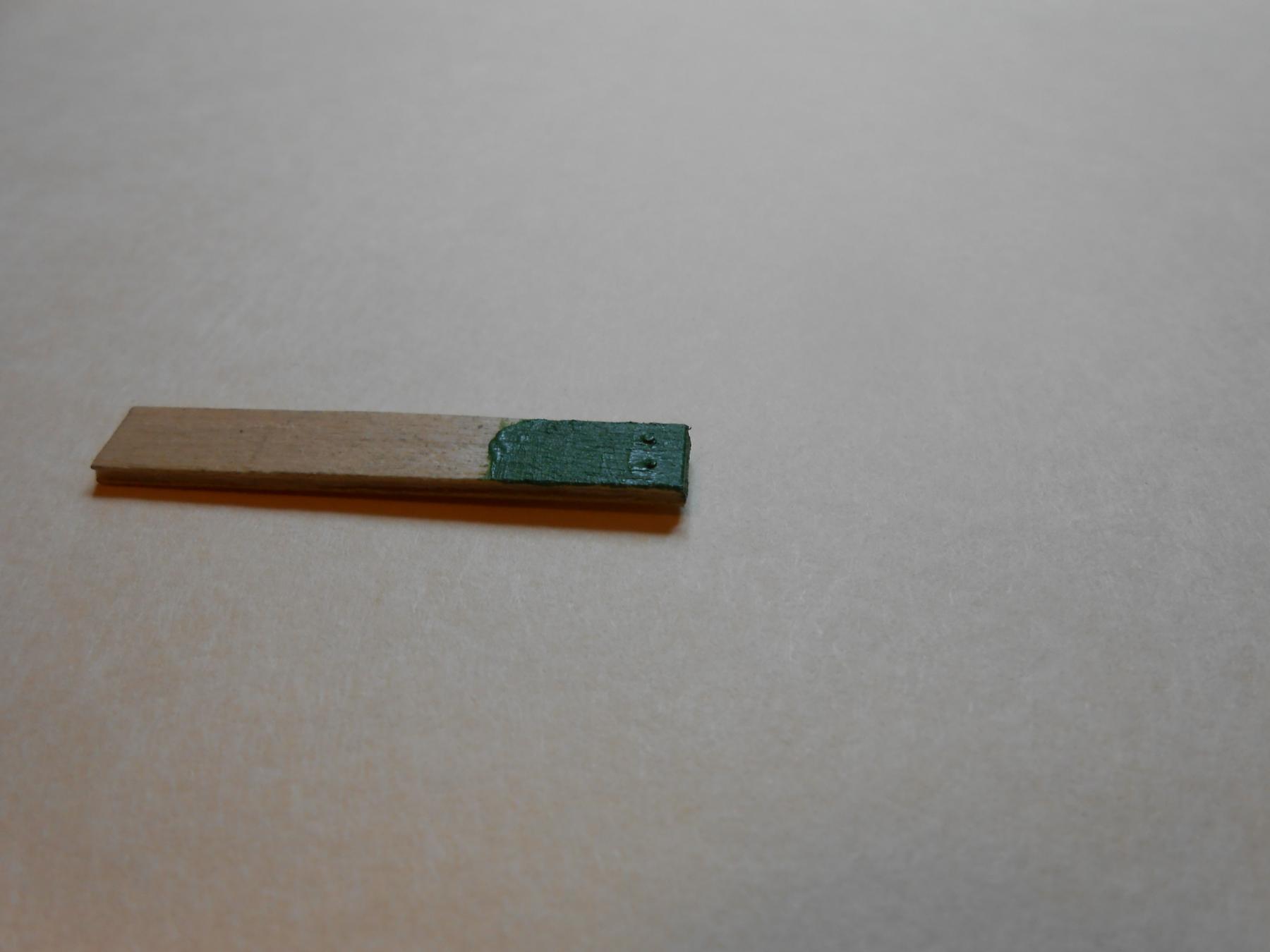
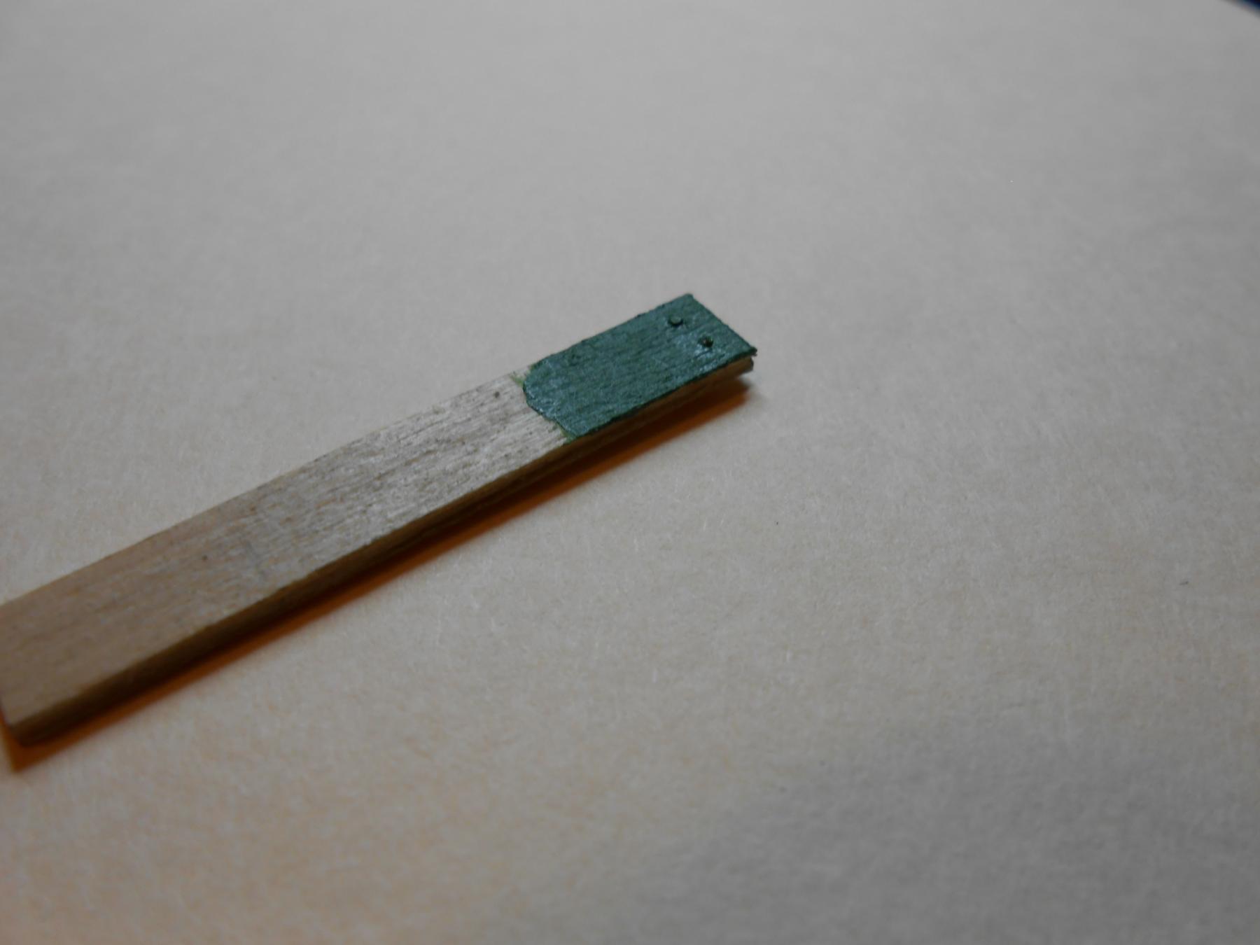
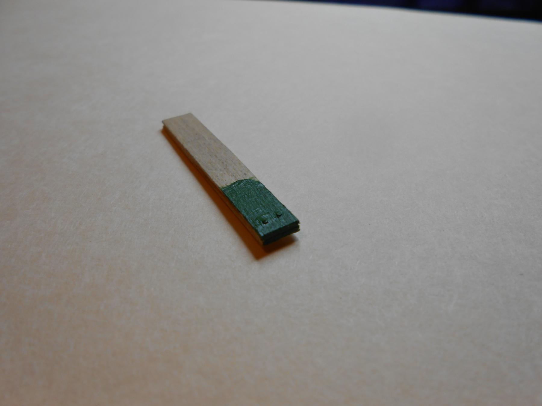
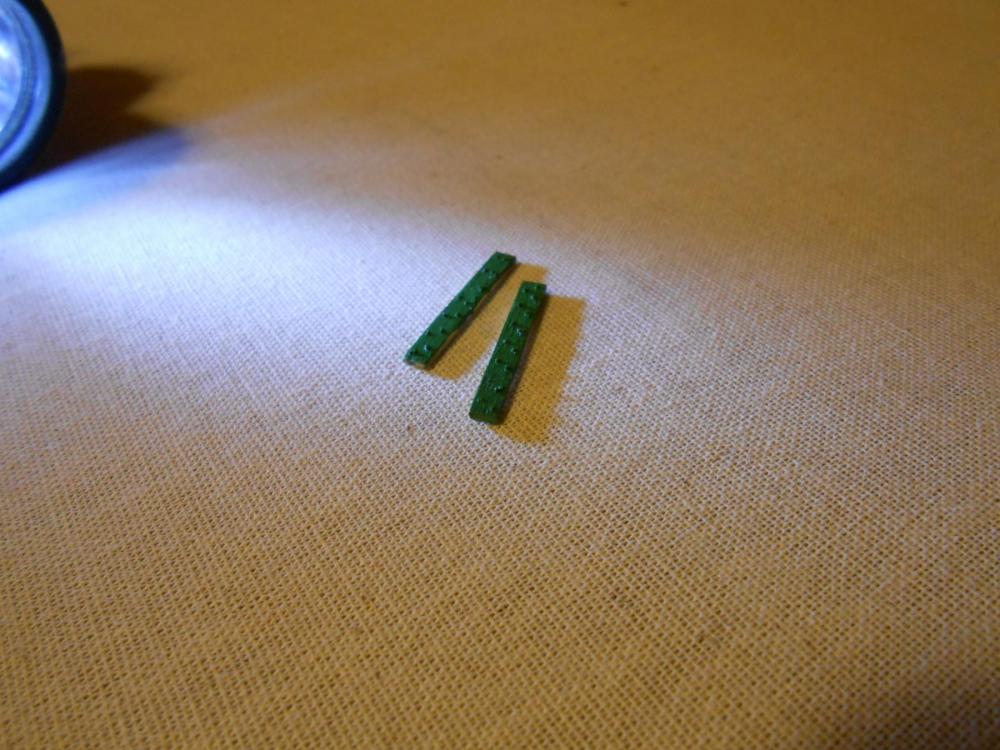
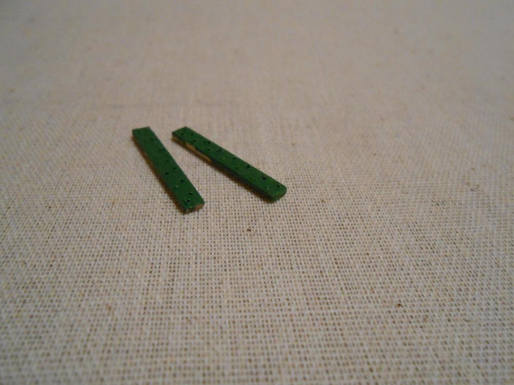
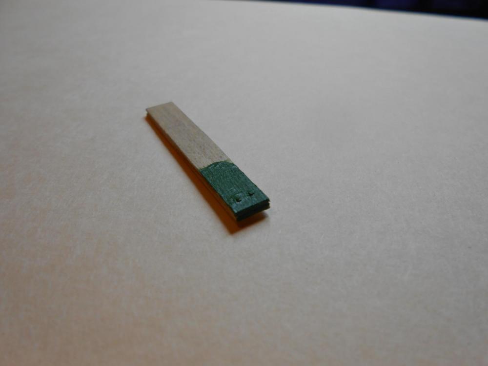
To finish off how I am going to handle the bulwarks. Pictured below is one of the jigs I have made to get my spacing of the bolts/rivets correctly placed. It is a simple affair, consisting of a fence, and a barely visible pin that positions the part based upon the last hole drill. The pin fits in the hole, the next hole is drilled, and the plank moved so the last hole drilled fits over the pin. This gives very accurately spaced holes, which are then filled with .015" brass wire. The wire is pre-cut, using another jig I made. It is simple a piece of wood with a hole drilled in it to attain the proper length of wire. Doing it in this fashion is much easier than trying to cut the pins oversized and then trim them after they are in position. This can be inconsistent, but I finally got the process down. You will see there are some shorter pins on the pieces that are shorter, which I made before I got the jig made right. These parts are by no means exact copies, and are just practice pieces. The spacing will be much more accurately staggered on the actual model parts. I just made these to test my process. This is a slow process, and am still questioning why I am undertaking this madness, but the results really do look realistic and I am liking how they are close to scale. I admit, they are a bit larger than actual, but they are close, and a good representation of the feature. Remember, these planks are only 1/8th" wide and 3/64th" thick. This process isn't perfect yet, but I am getting closer to good enough. These are the third and fourth tries I made. The first two were fails because the wire bent when trying to clean them up with a tiny file. Trying to straighten them out again resulted in destruction of the wood. But I am satisfied with the basic process at this point. I should be able to drill all the holes in a 24" piece of plank material, which is what I have. It is easier to work with a long piece than many short ones. The drill bit is .0145", so there is a slight friction fit between the wire and the wood. Once in place, CA glue is applied to the backside of the plank to secure the wires. This is precise and exacting work, and I don't recommend it. I wouldn't be doing it if I were sane, but I want the detail in this model. But I now know this is going to take me longer than I first estimated, and maybe as much as 4 times as long. Oh well... I want a model I can be proud of, and it doesn't really matter how long it takes as long as it looks right. Anyway, here are the photos. Matt


- 117 replies
-
- 5
-
-
- constitution
- model shipways
- (and 1 more)
-
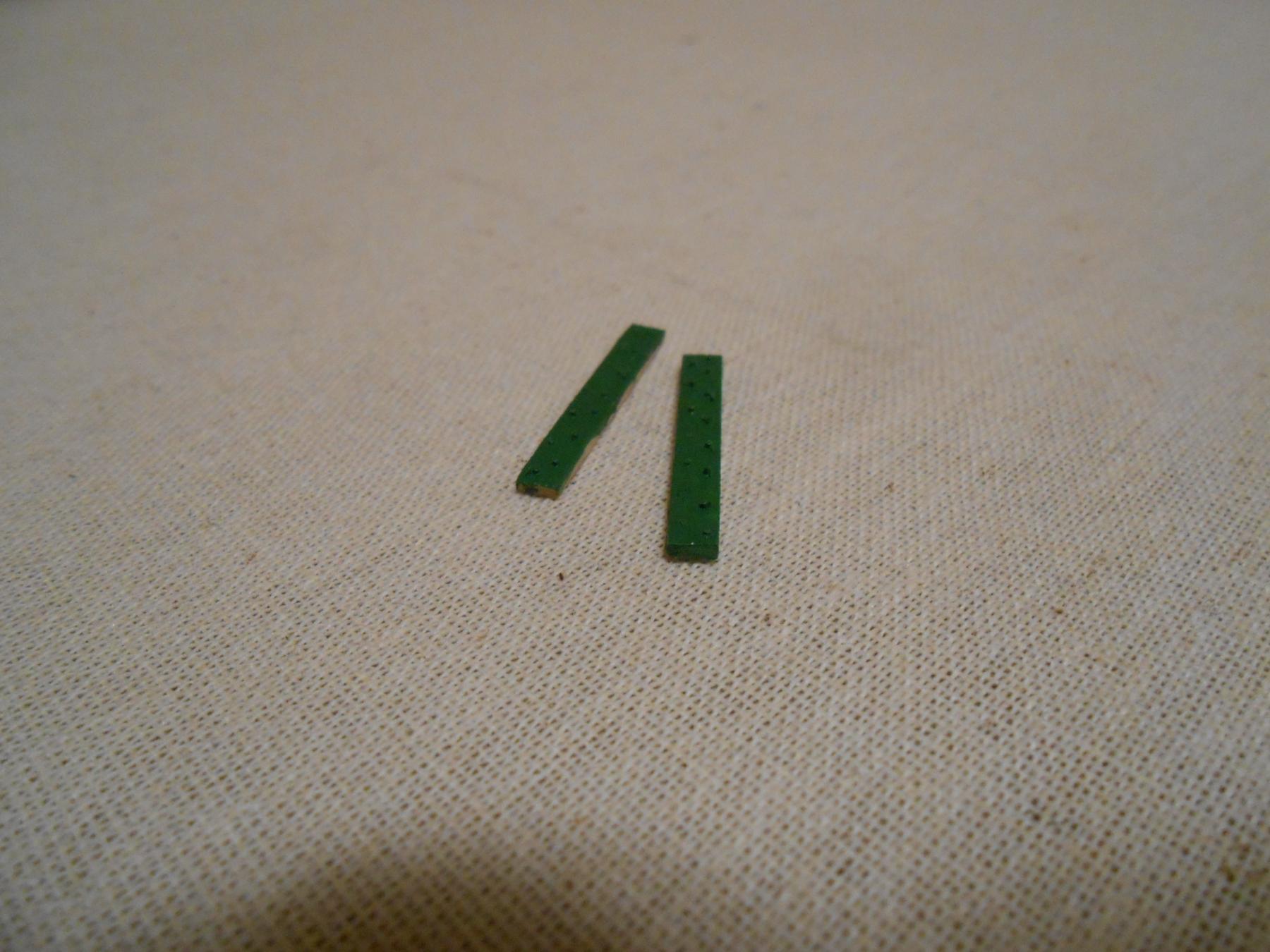
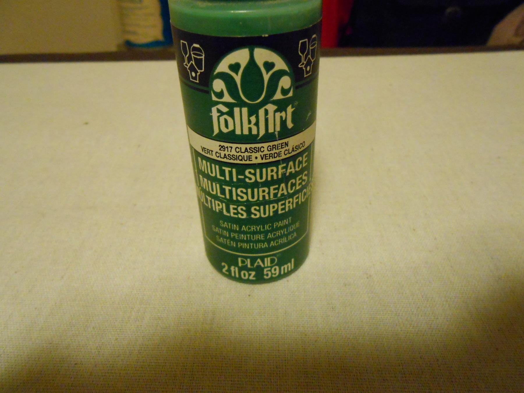
Thanks, David, and yeah... It is going to be a major undertaking, but it is a detail I thought was worth including. Rivets and bolts make military models look meaner... lol. But to tell the truth, it is going to be so subtle, that I doubt many will even notice it. The reason I want it there is for me... So I can look at the model, and know I came as close as I could. But like I said, it is a detail I don't believe anyone else will notice. The paint I used I picked up at Walmart... Just a cheap craft paint that they sell. I will insert a photo below of it, so you can see the bottle. It is a little darker than I want, but not much. A drop or two of white should bring it pretty close. I am sure as cheap as it was, it is neither light resistant though, nor color fast. I like the color, but want a artist quality paint so things don't fade as much over time. But if I did... Hey... Then I could just forget the drop or two of white, right? I am tempted to use oil paint, but that poses problems with drying, and glossiness, and it is risky doing a flat coat of acrylic over oil. What I will probably end up doing is using Vallajo paint. I have had great success with it in the past, it is not that expensive, and I have airbrushed it and manually brushed it on, all with excellent results. Once I get the drill press set up, and the jig made, I should know how long this is going to take. I am thinking maybe a week to do all of the interior bulwarks. I did the experiment freehand, and even with painting it took me maybe 10 minutes. But we are talking about over 1000 holes, I am sure. Maybe I will count for the record. It is my guess that it will probably take about 5-10 minutes per side of the 24" planks. The jig is actually quite simple to use, and anybody should be able to fabricate it after I show it. But then again, I doubt many will want to once they see how many holes there are to drill... lol. Here is the picture of the paint. Matt Here is the stuff I used for paint. It is called "2917 classic green". Matt

- 117 replies
-
- 5
-
-
- constitution
- model shipways
- (and 1 more)
-
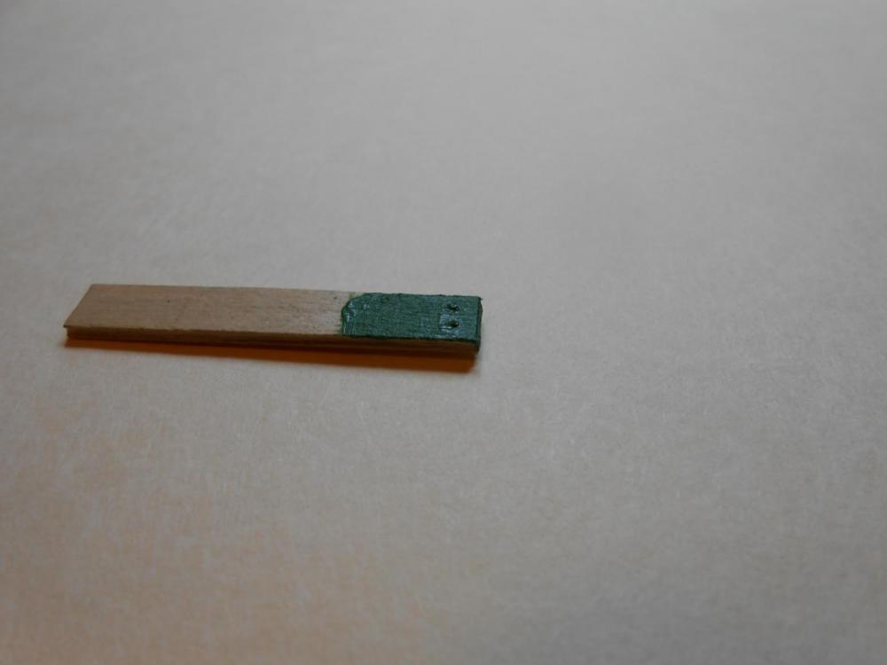
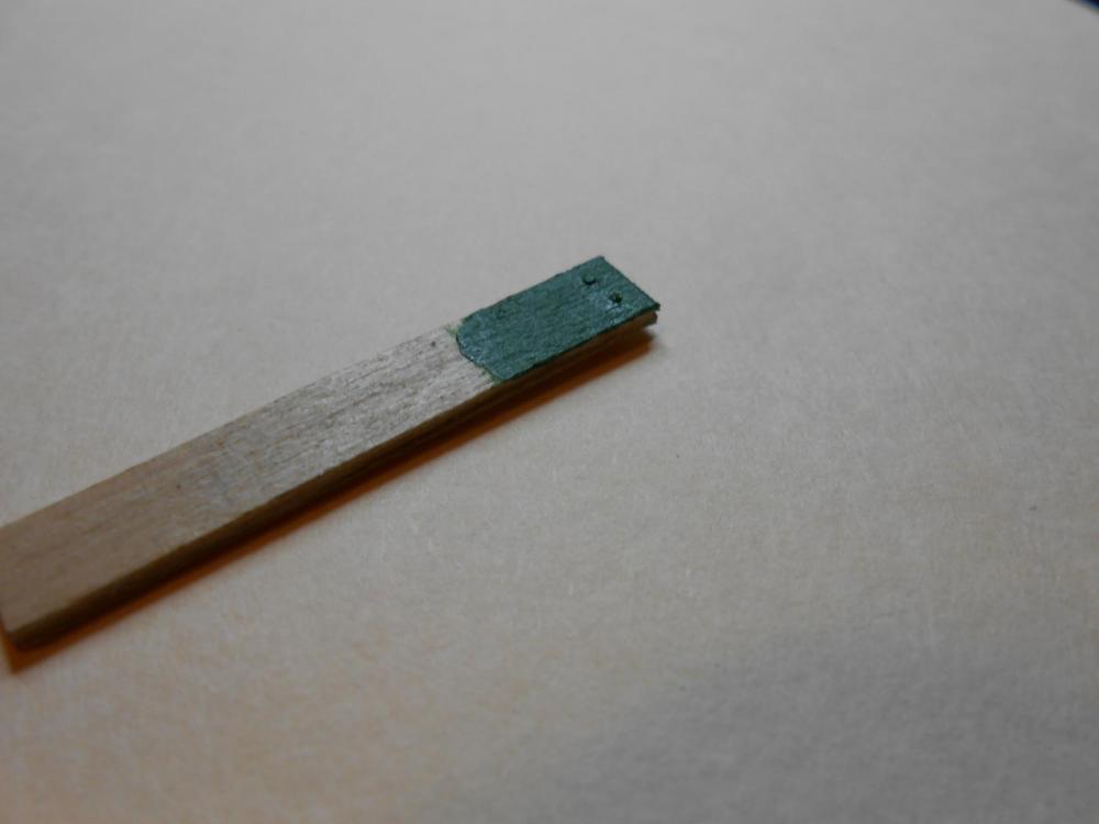
I had a lot of yard and garden work to tackle this weekend, so didn't get much time to continue working on my waterways. But while the chainsaw and tiller spun, I had some time to think about the best way to handle the bulwark rivets, which thanks to David Lester, I don't believe are rivets at all, but rather bolts threaded into Ogee nuts. Ok, I know the photos aren't great from my cheap little camera, but it is all I have at the moment. David's link to the google maps shoot of the Constitution is about 6 posts back. I urge anyone who is working on this ship to look at it carefully. Since I have never had the pleasure of touring her, the link was a real Godsend. I see so many details I would not have imagined. Thanks again, David. So contemplating how I was going to emulate the rivets/bolts, I finally decided the most realistic and accurate way was with brass wire. In the photos, I show .022" wire glued into holes drill in a plank and painted. They were inserted in the holes, cut to length, glued and carefully filed to final height. But when it comes to actually doing this, .022" is too large. By my calculations, this is about 1.5" real-world. So, I will be using .015" instead, which may be a little on the small side, but I am accounting for the thickness of the paint as well, which when you are working at this small scale, does make a difference. And when painting this test piece, I should have used a thinner paint, but you can see the shadow caused by it's thickness. Now this is going to amount to probably at least 1000 holes to be drilled in precisely the right spots. How can I achieve this? With a jig, of course. So I will build the jig, and get it set up for use on my Dremel drill press. This will give me exactly placed holes each time. I will post pictures and an explanation when I do this, which might be as early as tomorrow, we shall see. CA glue holds the pins in place. Matt
- 117 replies
-
- 5
-
-
- constitution
- model shipways
- (and 1 more)