HOLIDAY DONATION DRIVE - SUPPORT MSW - DO YOUR PART TO KEEP THIS GREAT FORUM GOING! (Only 20 donations so far - C'mon guys!)
×


MEPering
-
Posts
91 -
Joined
-
Last visited
Content Type
Profiles
Forums
Gallery
Events
Everything posted by MEPering
-
Thanks Bill, Jparsley and E.J. I appreciate the feedback being new to ship building as I am. I was fairly intimidated by the project when I first unpacked it, and still am, but not like when I first got it. I was confident I could accomplish the tasks that were necessary to have a reasonably nice ship when it was finally finished when I ordered the ship. But then when it arrived, I saw the incredible amount of time it was really going to take. I finally asked myself how I was going to eat this elephant, and of course the answer was, "One bite at a time." If it takes me a year to get her planked, so be it. But I am having so much fun, it really doesn't matter. And I understand what you mean, E.J. I too am tempted to do more scratch building on this model than is called for. I also have a full woodworking shop, and metal shop as well as a forge and casting capabilities. The things I really am not impressed with in this kit are the cannon and carronade castings. I am so very tempted to make them from brass on the lathe, but am trying my best to hold back. I think if I do decide to actually do that, I will just make a couple of wax masters and cast them in brass. But then again, I may turn them all in brass on the lathe. But like I said, I am trying to hold back. As far as wooden parts go, I already know I am going to be turning parts for the bitts and posts for the fife rails. Some tiny work to be sure though. I think sugar maple should fill the bill though. Matt
- 117 replies
-
- 3
-

-
- constitution
- model shipways
- (and 1 more)
-
Hi David, Your resources continue to amaze me... That definitely shows they are mitered. I really need to do more research, it is becoming obvious. It didn't make sense that endgrain would be exposed in this environmental situation. It would be asking for rot to set in, even if painted with the porous paints they had back in the day. If it had been practical, they would have even coated the running lines with pitch or tar as well. Thanks, David. Matt
- 117 replies
-
- 1
-
-
- constitution
- model shipways
- (and 1 more)
-
Nothing at all wrong with that, Jparsley... They look realistic, as do the other items there. It is fun to scratch together things like this, IMO. Matt
- 60 replies
-
- 4
-
-
- king of the mississippi
- artesania latina
- (and 1 more)
-
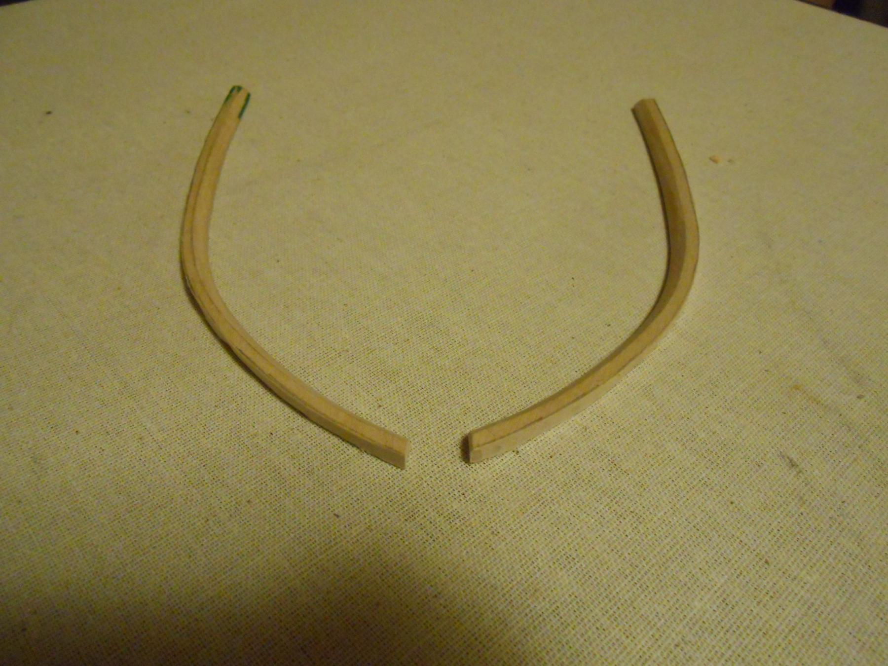
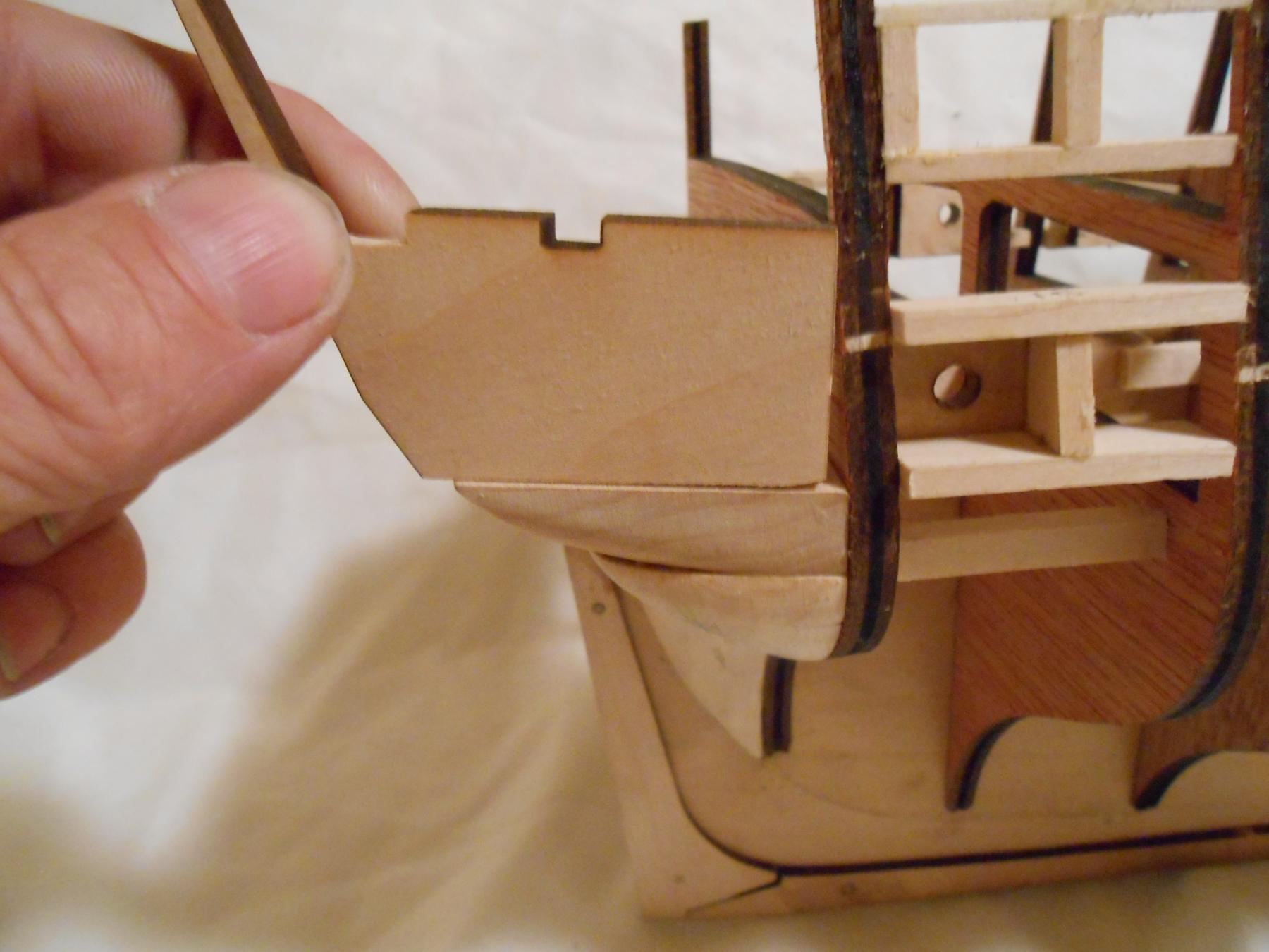
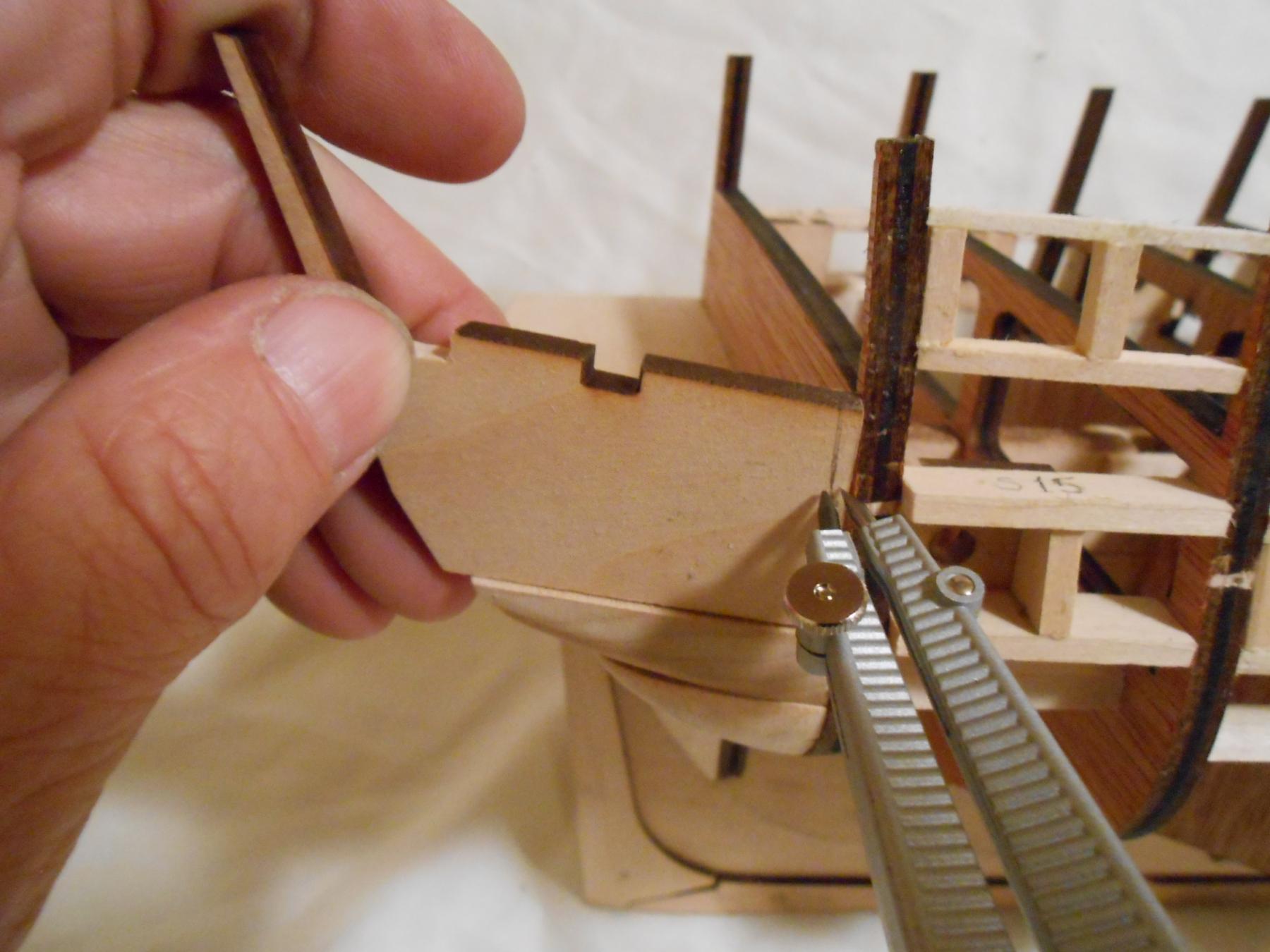
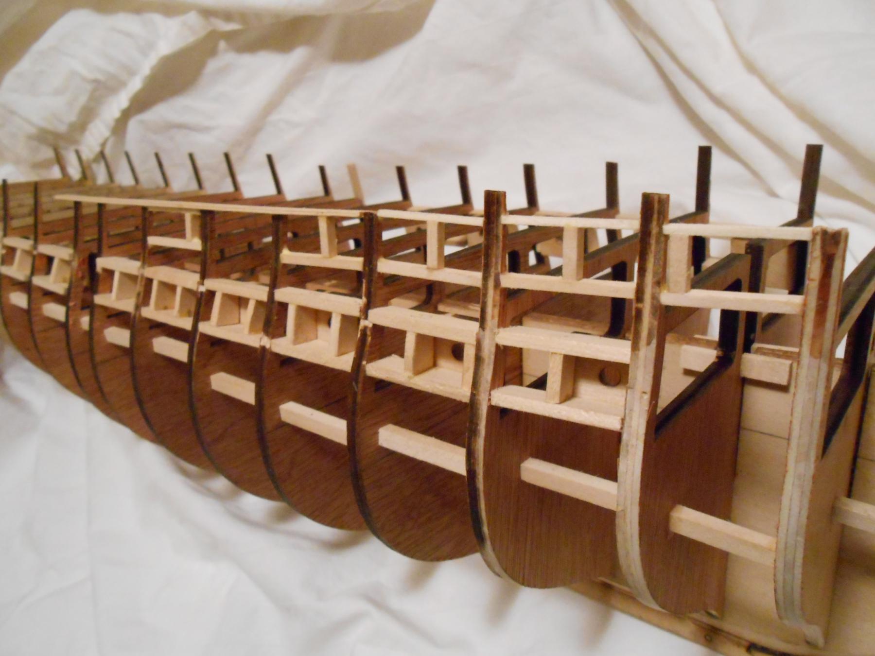
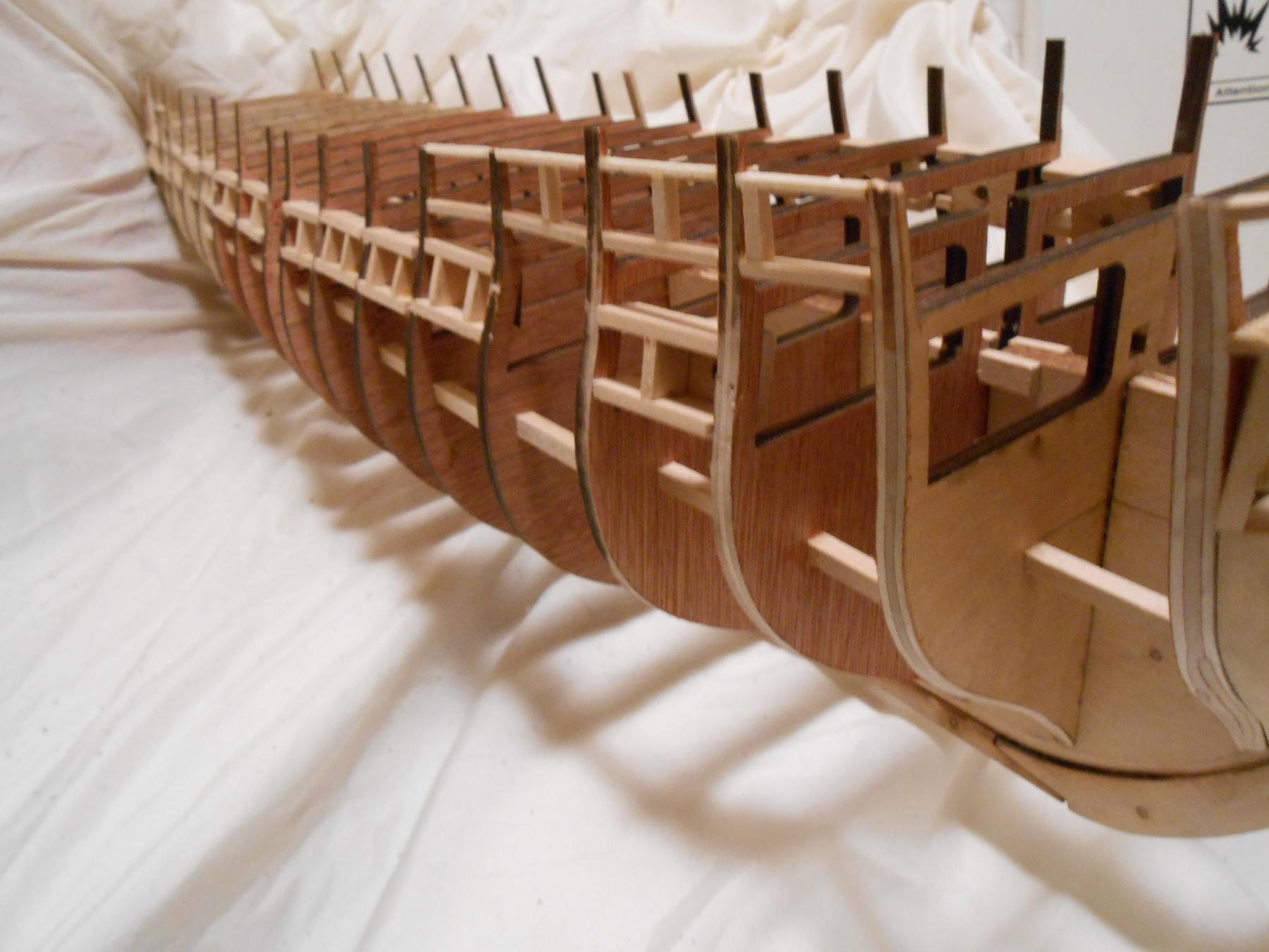
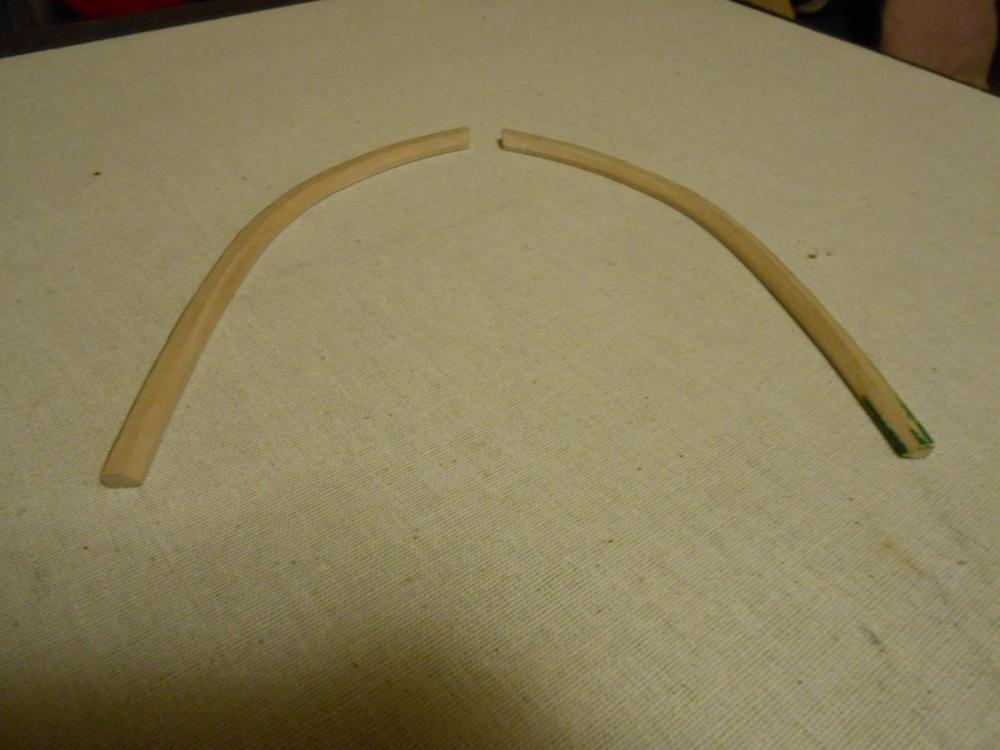
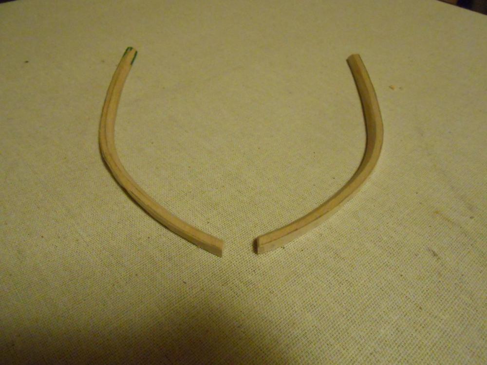
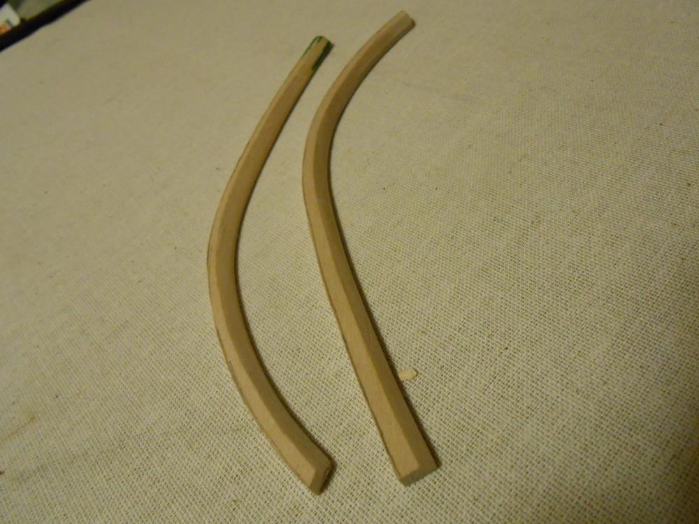
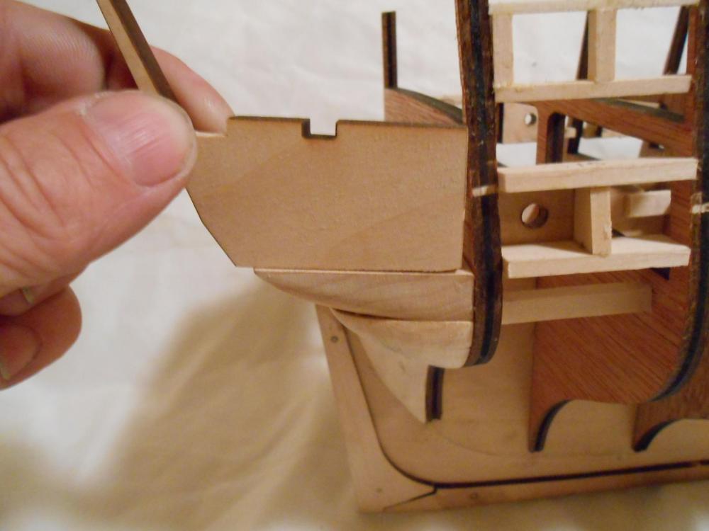
Now that the transom is mostly in order, except for the stiffeners and port framing, I am turning my attention to the waterways. I have a few pictures of the bow waterways, but the sides are also done too, but I chose not to show them, since they are comparatively simple compared to the ones at the bow. I have them almost perfectly fitted to the ship, but I have a bit more fine-tuning to do before gluing them in. I also need to make the transom piece, which I am having a bit of confusion with. In my plans, it shows the sides going straight back, with the transom waterway butted up against them. But it seems like the two pieces should be mitered together to me. The reason I believe this is so less end grain would be exposed to the elements, though I know the waterway was painted along with the bulwarks. I can't find any reference to this in AOTS book. Any help would be appreciated. The way I made these pieces was to make a 5/32" piece and made a template and cut out the curves, and then determined the height of the planking, thus setting one edge of the bevel. I chose not to bend the wood hear, simply because it was easier to do it this way, I thought and still think. It may seem that the answer for the upper width is just to cut it at a 45 degree bevel. I don't think it is that simple. It depends on where the planksheer lands on it, so it can't be determined exactly until it is mated to the planksheer. The bevel I cut, which I know is not easy to see in the photos, was cut entirely by hand with sandpaper and a file. But I am very used to using hand tools, so it was not as difficult as it might seem. For some reason, people seem to have a fear of doing things with hand tools. But it takes just a little practice, and you will be surprised what can be done with some chisels, riffler files and sandpaper. The last picture shows what can be done with patience and just hand tools. The spot of green on the end of the one was me testing paint for the right shade for the bulwarks. Matt
- 117 replies
-
- 5
-
-
- constitution
- model shipways
- (and 1 more)
-
Tom, I think that is the solution for the cleats. I would spend a day or two making all of those and I am sure they wouldn't look that good. Yours look great, so I think I will go the same route when the time comes. One thing I have done with hemostats in the past is wrap the jaws with a couple of layers of electrical tape. This pads them enough that the jaws won't mar the wood. Plus, it is temporary, and I can remove the tape when switching back to metal or other materials they won't mar. Matt
- 1,348 replies
-
- 2
-
-
- constitution
- model shipways
- (and 1 more)
-
Very cool. What did you make the bales out of , Jparsley? Matt
- 60 replies
-
- 3
-
-
- king of the mississippi
- artesania latina
- (and 1 more)
-
Harlequin, I hope your son never wishes he had taken up modeling instead. But you made a super buy there at only 10 pounds. Just the materials alone are worth that much at least. I would be tempted to get those plans exact photocopied, and store the old ones in case you need them. It looks like the damage is minor at this point, and not much a straight edge or French curve couldn't fill in. Matt
-
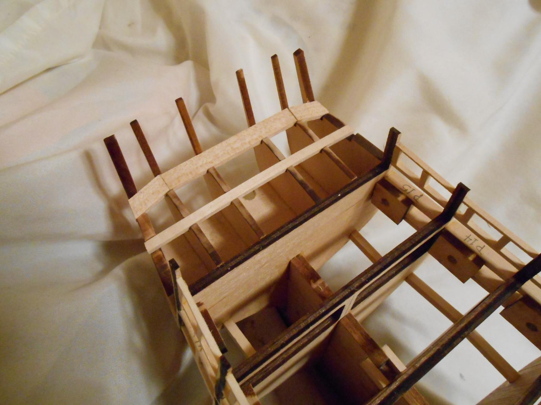
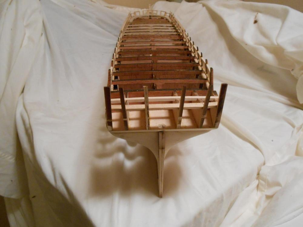
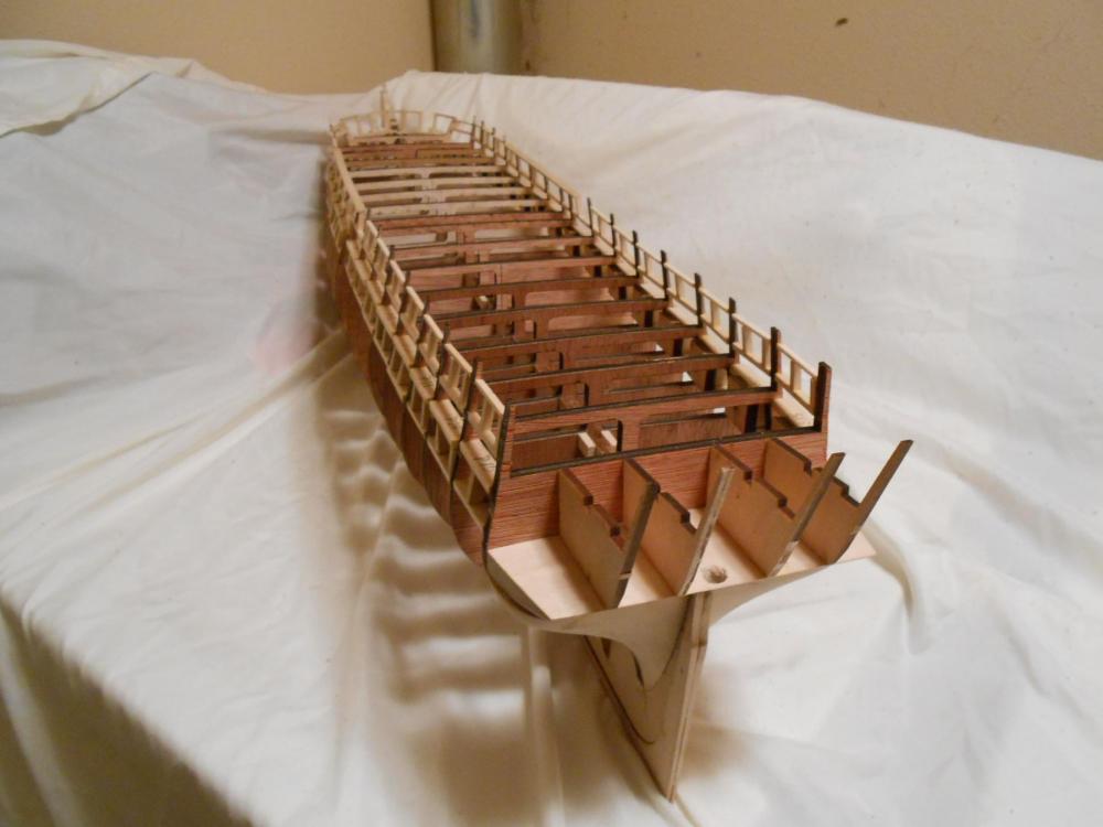
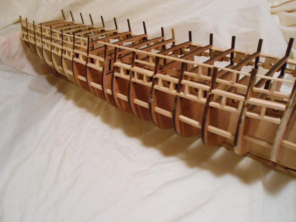
Well, David, I am glad you took another look. It may not be a great picture (few of mine are, I know), but the information is there. I am able to see how you handled it... About the same way I had planned to. It is good to see too, since this seems to be a logical solution by someone other than myself... lol. I did get the deck braces in on the transom, though I haven't put on the stiffeners yet. The pictures are a bit deceptive. My cheap camera, though it has a macro mode, still has a terrible problem with fish-eye. In one of these pictures, it will look like the frames are leaning outward, but actually they are perpendicular to the horizon. I say to the horizon, because the the deck is curved, and they are not perpendicular to the deck. I did cut the rear deck beam since there is no way it would have fit as the transom frames sat. This doesn't bother me, since these pieces will not be seen. Also, the deck beams are heat-bent in order to conform to the curvature of the deck. You will also see in one of the pictures I have begun working on the waterways. These are somewhat complex little parts, and I haven't started beveling them yet, but I think after the stiffeners on the transom frames, the beveling is next. It looks like the 45 degree angle only holds after bulkhead "C". In front of "C", they are a bit more shallow. But most of the bevel is on the side that fits against the bulwark supports, so fairing the interior bulwarks needs to be done prior to fitting of the waterways, so maybe that should be done after affixing the stiffeners. Anyway, here are some pics: Matt

- 117 replies
-
- 6
-
-
- constitution
- model shipways
- (and 1 more)
-
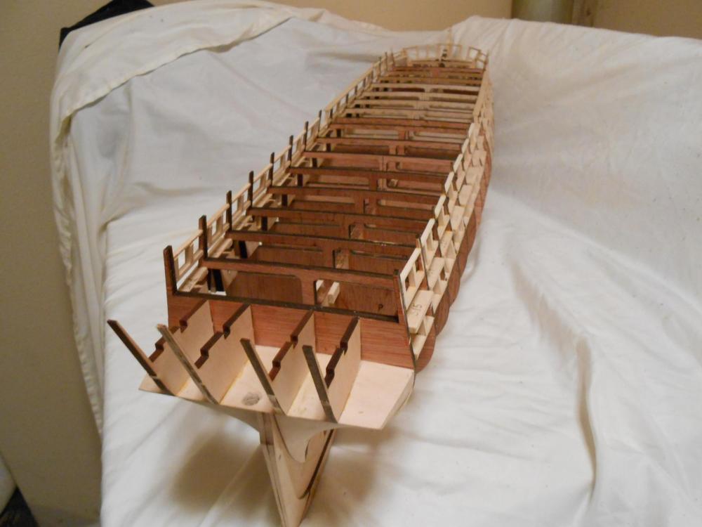
Well, I am progressing on the transom, correctly or not. I still don't understand the reason the frames had to be so severely modified, but they have been on my Constitution, and what will be will be. If all else fails, I can always start over on it. But while doing the transom, I started thinking about how I was going to handle the bulwarks. This is a subject that I have been thinking about for some time. That is the spikes or rivets which line the bulwarks, to be more specific. It is a feature I definitely want to model, but the best way to do so is what has been making me think. I have considered MicroMark, Tichy Train, and Archer rivets. With the exception of the Archers, these all are out of scale, and Archer's are too pricey. So I have decided that I will make my own. It took me a few hours, but I think I have figured out how to do it, but it is going to take a bit of work. It is going to take some careful milling and manufacturing, but I think I can do it. My plan at this time is to cast them in resin. Not individually, but in strips connected with something similar to a tree on a plastic model. Once mounted, the tree is cut away, leaving only the rivet/spike heads. This is tiny, tiny work, and I don't recommend it except for the extremely mad, but I do think it will enhance the model while being closer to scale than most I have seen. That is the key to a good model, the proportion in scale. As I said, this is going to be very tiny, very precise work. As such, it is going to take me a couple of weeks to present any results of these experiments. But I am pretty certain this should work, using pressure casting techniques to get the resin to fill the heads of the rivets. With parts this tiny, the hardest thing is going to be getting the resin intimately mixed enough to pour in a reasonable amount of time. This is best done with a slow-setting resin, but I don't have that to experiment with that right now. My molds will be made of brass, since it is easier to work with than steel. Transom framing should be done tomorrow, so maybe I will have some pictures tomorrow. Matt
- 117 replies
-
- 4
-
-
- constitution
- model shipways
- (and 1 more)
-
I have consider buying one of these for a long time. I hadn't really thought about it for ship modeling purposes though. I wanted one to flatten silver wire for doing wire inlay in the work I do. But it looks like it does have a purpose here... It had just never occurred to me, I guess. Matt
-
David, Thanks for that link. I will go through it and see what information I can glean from the guy. Looks like he has done a pretty good job, from the few pages I have skimmed. And I will have to look at my pictures again to see if I can find that detail on the breach line connections, as well as his sight. As for those little nails, I never saw a reference to them in the instructions, and the only thing I could figure they my be used for was temporary holds during the planking process. And they give you so many. I might use them for the chainplates, but only after turning down those huge heads on the lathe. Tedious work, but I am pretty frugal (i.e. cheap), so I might just do that. But please let us know how your sewing store nails work out. Matt
- 117 replies
-
- 3
-
-
- constitution
- model shipways
- (and 1 more)
-
I bet the are difficult, David. They are very delicate photo-etch, and I just hope mine come out as good as yours. What did you use to affix them to the hull? Matt
- 117 replies
-
- 1
-
-
- constitution
- model shipways
- (and 1 more)
-
Thank you, EJ_L and Alde. I have tried to build as close to the plans as possible, but I also realize those are not quite as accurate as I would like. In fact, as I said, my construction was spot on, but I still had a whole 1/16th discrepancy in the plans and the actual build when it came to deck height. I am not liking that, but I have little choice. But then again, I compare the model to the AOTS by Marquardt, and mine looks more accurate so far, so maybe the frustration is worth it. It really doesn't matter... I will get it to where I can say it is acceptable. And it is not that far from that now. All I can think is that Model Shipways made the frames oversized to accommodate for laser burn, but I am not certain. I have never had any experience with laser cut parts before, so I really can't say. I really am just going by what I think is right, and though that is not a way I would prefer to go, I do have the AOTS and my eyes to try and attain what can be considered correct. Matt
- 117 replies
-
- 4
-
-
- constitution
- model shipways
- (and 1 more)
-
Elijah, I have used 1/4" painters tape for these sorts of things in the past. But I would suggest that maybe a piece of cardstock would be better for your application, if I am correctly understanding what you are trying to do. Know though, this is my first ship, and I have never planked a ship before, so my advice should be taken with a grain or two of salt. But cardstock doesn't stretch easily, and it is good for patterns like this. Matt
- 701 replies
-
- 3
-
-
- phantom
- model shipways
- (and 1 more)
-
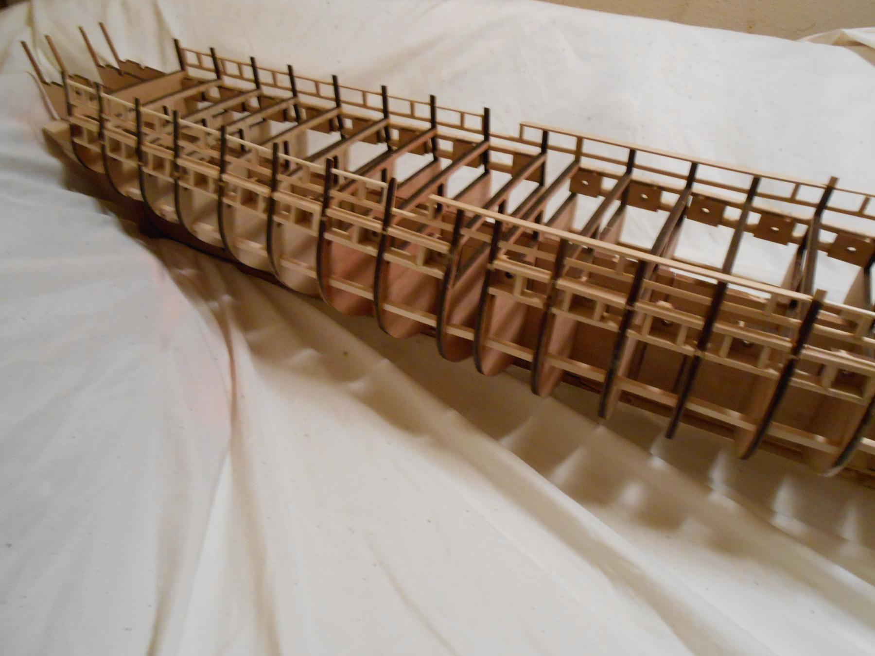
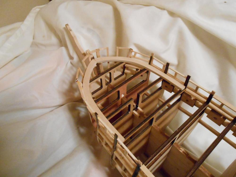
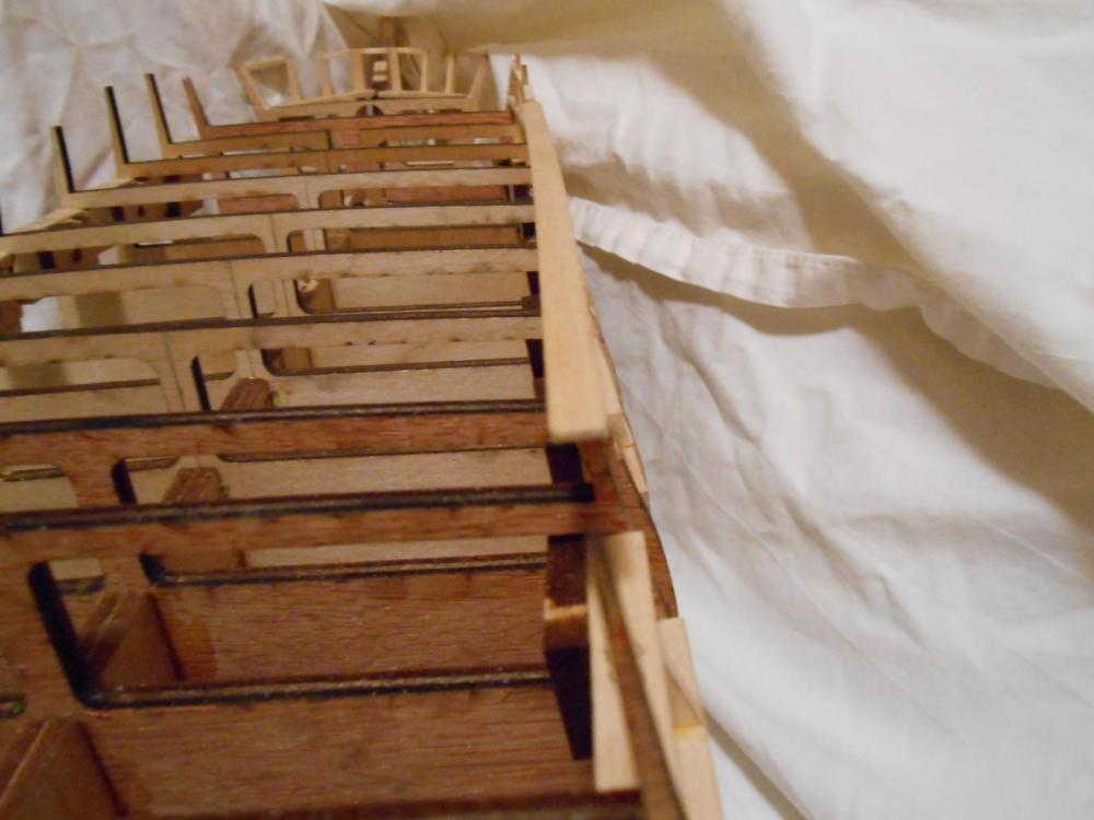
I finished the gun ports today, and everything you will see in the following pictures (as poor quality as they might be) is glued in and probably should not need to be changed. I also framed the cathead openings, which the instructions don't tell you to do. I have been through the entire instruction book, and couldn't find any reference to framing these, but I felt it was prudent to do so, and that it couldn't hurt. If it is a mistake, I can always tear it out. As you can see, I am still dealing with the transom. I went through measurements and dimensions and calculations, and can find nothing wrong with the way I have done things, but still, things aren't coming out as expected. I am absolutely certain my counter is made correctly, as I checked it many times against the drawing, and it is exact as can be expected. My only conclusion with the problems I am having with it is a compounding of minor errors with the laser cut parts and the plans. I am certain my construction has been correct. I have an idea as to how I will correct that, but that is a post unto itself, so once that is done, which is my next step, I will report on it. Next, I will fix the transom, finish the main rail, and topgallant rail. As I have mentioned in other posts, I will not be affixing the hammock or gangway boards, since I am sure they would just get broken in the planking or coppering process. If you look at my gangway, you can see it is easy to avoid mounting the boards and still give the support that should be behind the planking in these areas. I am surprised that the instructions or plans have a butt-joint for support of the planking. With my method, there is definite support behind the planking. After that will be installing the inner plank shear and water ways, fairing, and planking can start. I think I will hold off on installing the outer plank shear until I can take some measurements to confirm it's position during planking. I have been working on the ship for 1 month now, and feel progress is going well. I should be ready for planking to start next week, actually. Then things will slow down a lot, I am sure. Here are some pics: Matt


- 117 replies
-
- 7
-
-
- constitution
- model shipways
- (and 1 more)
-
Those strakes don't make any sense to me... They seem like they would accomplish little but serve as a place for barnacles to thrive. Wish I knew the logic behind them. Matt
-
I think it would be interesting to be able to keep a running log of hours spent, EJ_L, but I am interrupted so much with phone calls and my mother-in-law, who lives with us, and my father, that it would be virtually impossible as I see it. I think the longest time I have been able to spend on just building without interruption is about 40 minutes. I would love to track my hours, but it just isn't practical for me. But thanks for the words of encouragement... I am keeping calm and carrying on. But it really does amaze me how much can be accomplished just by working on a project for just a few hours a day. I had nothing but parts less than a month ago, and now, I am approaching planking. Granted, waterways are going to be a bit complex, but I am estimating that within a month's time I should be ready to begin planking. The instructions, I am finding, are more like guidelines of what should be done first. They don't really tell you how it should be done, but just to do it. I know that the writer assumed you know what you are doing, but it would be nice if he went into just a bit more detail. The plans actually say more about how to build it than the instructions. For a model that supposedly retails for US$700, you could expect a little more. Enough of my complaining though. It has been really fun to jump through the fiery hoops and figure some things out, and change the order of things a bit, knowing my own limitations. For instance, they tell me to mount the gangway boards and hammock boards before planking? I am sorry, but I refuse, since they would get broken in the planking process. Such misguided instruction is not helpful to people who want a quality build. I will place a temporary spacer block to support the rail, but I won't affix the board until the hull is coppered. Matt
- 117 replies
-
- 4
-
-
- constitution
- model shipways
- (and 1 more)
-
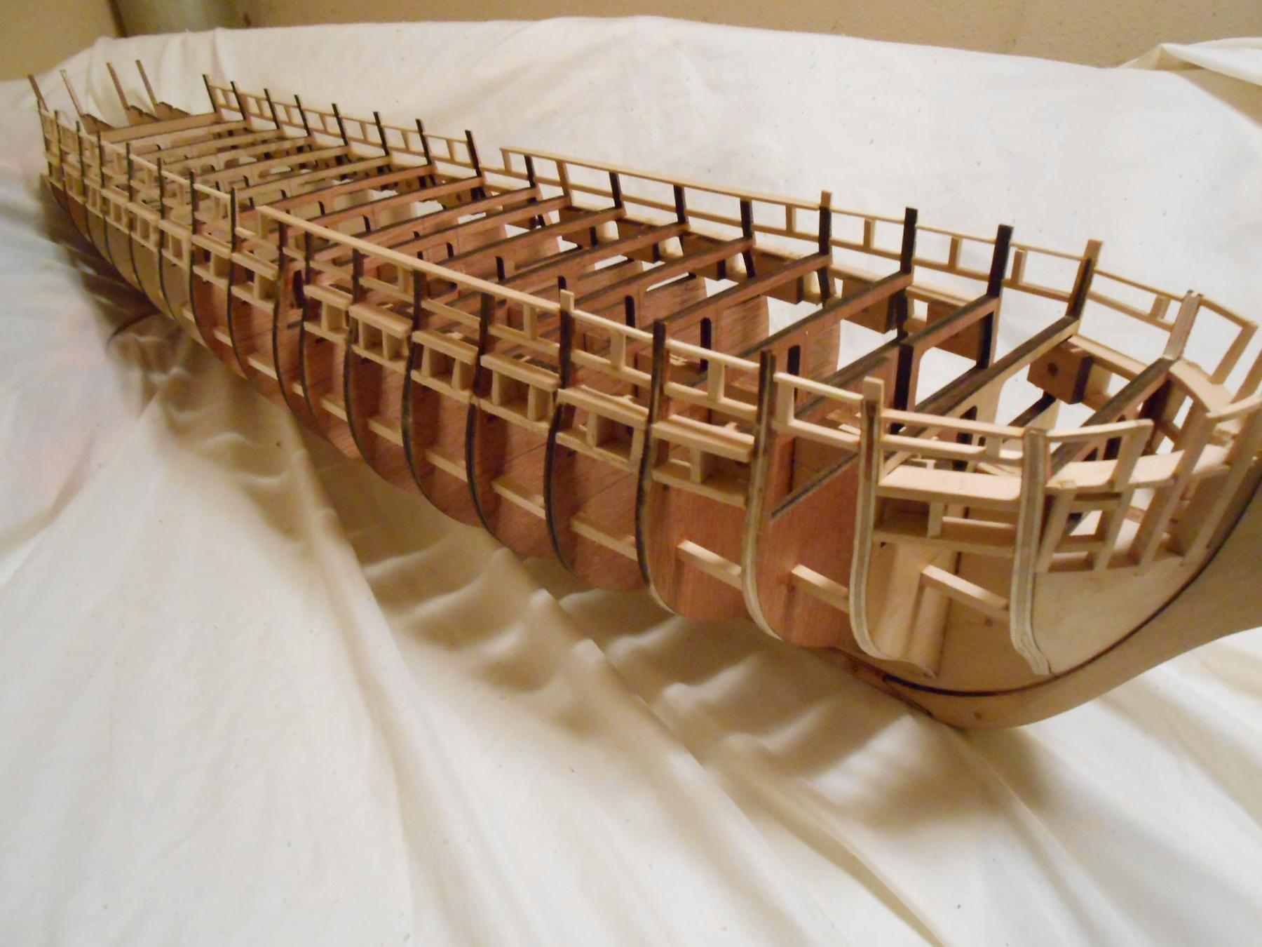
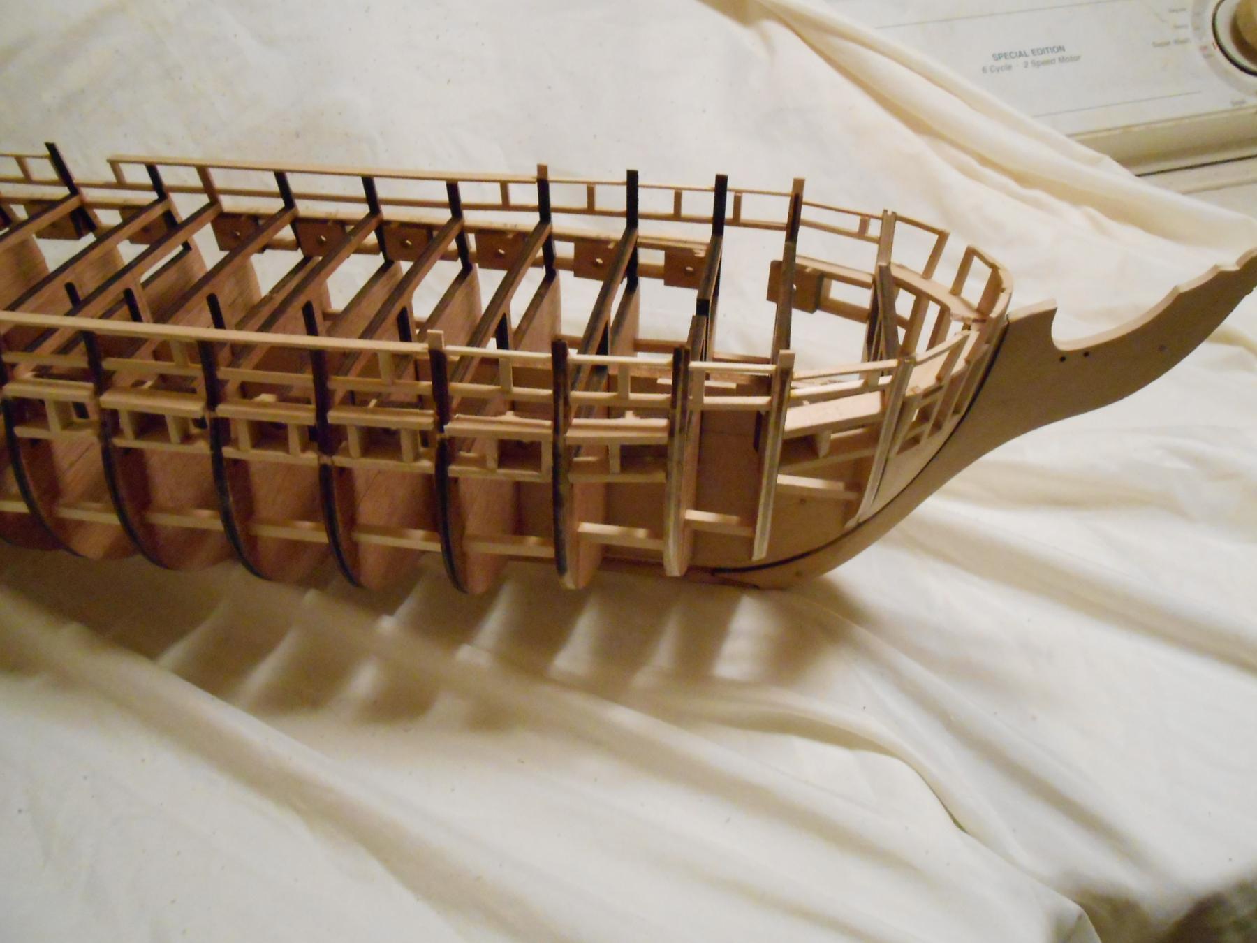
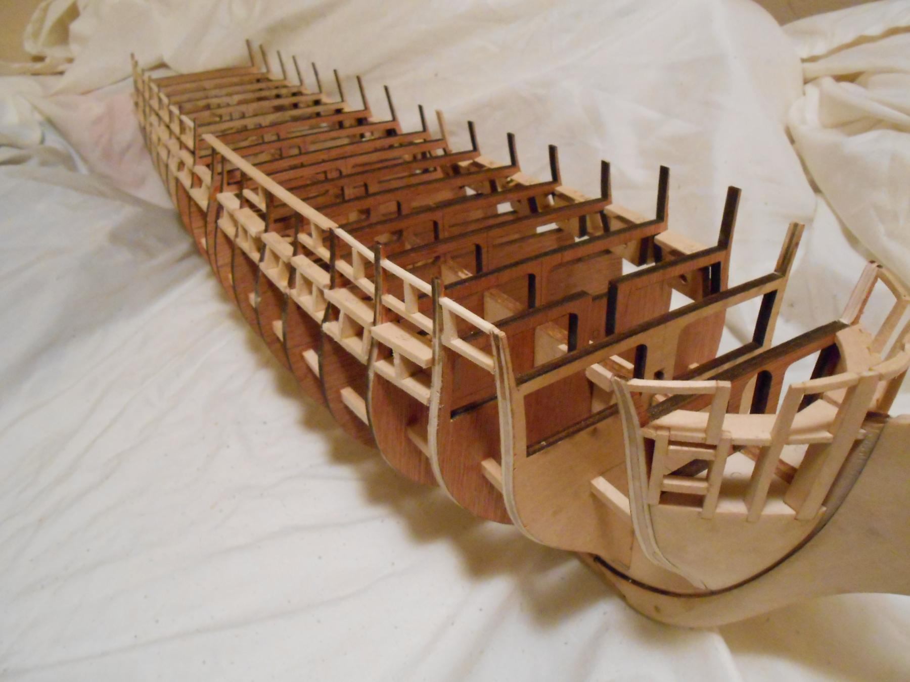
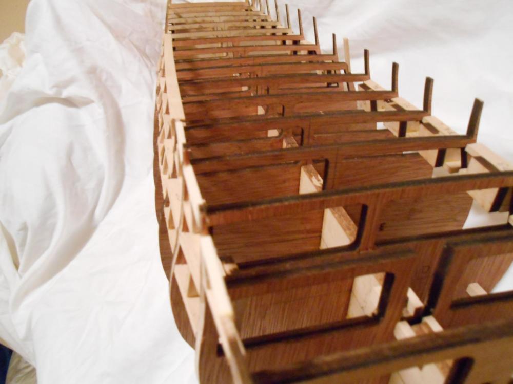
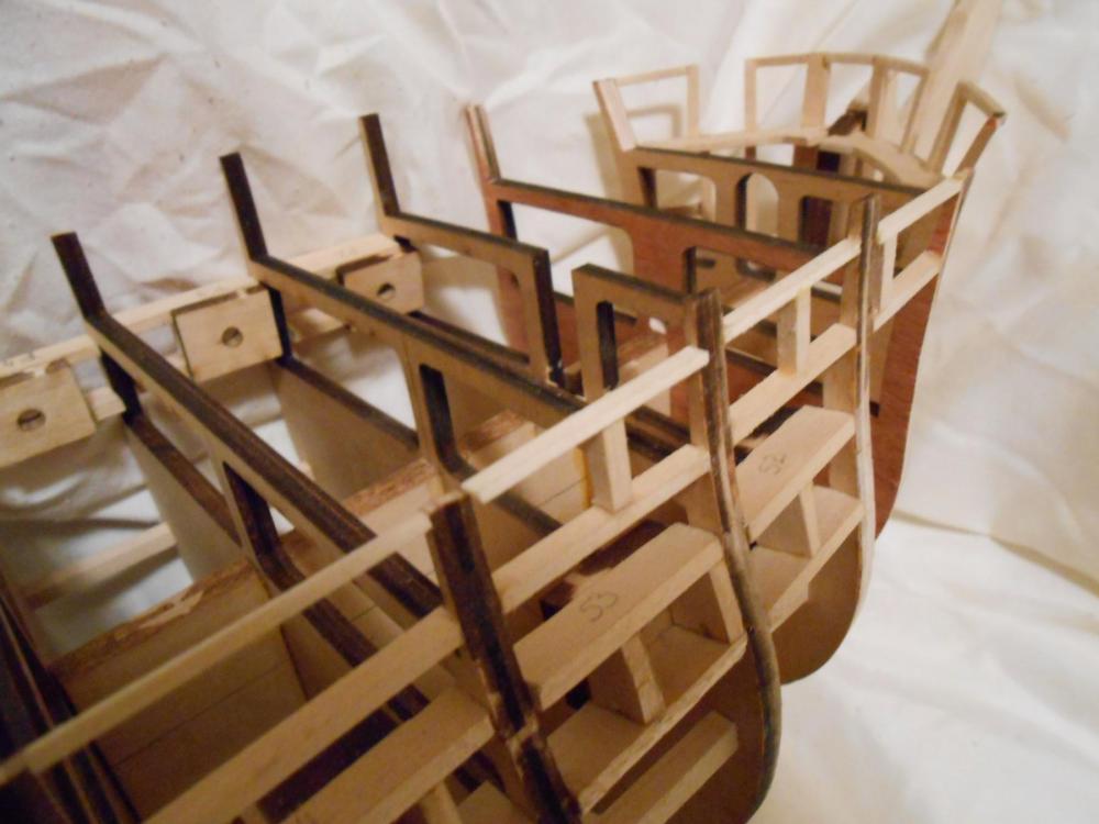
Thanks for that insight into how your build was, David. I rechecked and rechecked my measurements, and every thing seems kosher here. I thought I might have not made my counter deep enough, but it is spot on. I did compare my unmodified transom frames with the drawing, and noticed and extra bit of length, but it shouldn't have been enough to justify the almost 1/8th inch error I have. I think I will finish the port side gun ports while I think about it. Following is a picture or two of the starboard side gun ports. They are glued in now, and if I had it to do over again, I would probably not build the gun deck ports off-ship. I would probably stick build them in place if I were to do it again. There is really no advantage to making them separately, and they require a bit of adjustment while fitting each one for gluing. I made myself more work, in other words. But what is done is done. I should have the port side completed to this same point in 2 days though, if nothing of momentous importance rears it's ugly head. I did take a moment to stand back and really look at what progress I have made to this point, since it is 4 days short of a month since I started this build log. I know I am not a fast builder, and I realize I am trying to take my time building this ship. But I thought I would have been further along by now. And then I stopped and really thought about it. I considered how many parts had to be scratch built, and just how many there were. I figured it was about 150 parts in the ship total to this point. I decided that I should count them, and see how many were actually there, and figure out how many were actually needed to bring both sides to where the starboard side is now. I was genuinely surprised. In 2 more days, I will have 352 parts glued up. That includes the transom frames. At this moment, I have 262 parts in place, most of which have been custom cut for their unique space. I really had no idea so much went into these ships, but it is a pleasant surprise. It has been a very satisfying trip. I really have to commend you all who take on this challenge. It is a lot of work. Fun work, nonetheless. I know I will have a lot of fairing to do... lol. Anyway, here are the pics: Matt

- 117 replies
-
- 9
-
-
- constitution
- model shipways
- (and 1 more)
-
Papegojan 1627 by mati - FINISHED - 1/48
MEPering replied to mati's topic in - Build logs for subjects built 1501 - 1750
I concur with Mati on the Brass Black from BC. I use it quite a lot in my engraving, and it does a fine job of getting a really nice and tough black finish on brass. It contains Selenious Acid and Fluoboric Acid, so rinsing within a minute or two of application is necessary or pitting can occur. I will be using it on the brass that needs blackened in my current ship build... Before that brass is attached to the ship, of course. Matt -
I know that my photography skills are poor, and my camera isn't that good either, but the pictures are as good as I could get. I will have to go buy a tripod one of these days. Anyway, I now have completed all of the gun ports on the starboard side. I could start work on the port side, but I decided it was time to deal with the transom, which I have been putting off since the laser cut parts aren't that well cut. I am not faulting Model Shipways for this, but this angle I am showing in these pictures could have been done by them. But then again, maybe they were trying to accommodate for builder errors. This seems likely. If you look to the rear, you can see the overhang of the transom frame over the counter, and at the front, you can see the huge gap between the bulkhead and the frame. My solution for this is to remove the excess wood. I will use a jeweler's saw for this, but it could be done with a sander probably faster. In order to cut less and come close to the angle I wanted here, I used a compass to transfer the line to the transom frame. When I used to work as a remodeling carpenter, I used this trick frequently. Like cutting baseboard for uneven floors, or hanging cabinets on uneven walls. You will notice that the space at the bottom of the bulkhead is not as great as the space of the overhang of the frame over the counter. I will use a file or sandpaper to correct that later. You can also see in the pictures the completion of the starboard gun ports, except for the last one which is why I needed to finish off the transom framing. Also, the transom must be done in order to do the windows and chase ports there. I know that they were not original to the ship, but I am sure they wished they had them in the Great Chase. But it is easy for me to sit in my chair and speculate about why were they so silly as to not have included them in the first place. This ship was a state-of-the-art war machine at the time, and all circumstances couldn't be seen then. These 2 pictures should be self explanatory. Matt

- 117 replies
-
- 7
-
-
- constitution
- model shipways
- (and 1 more)
-
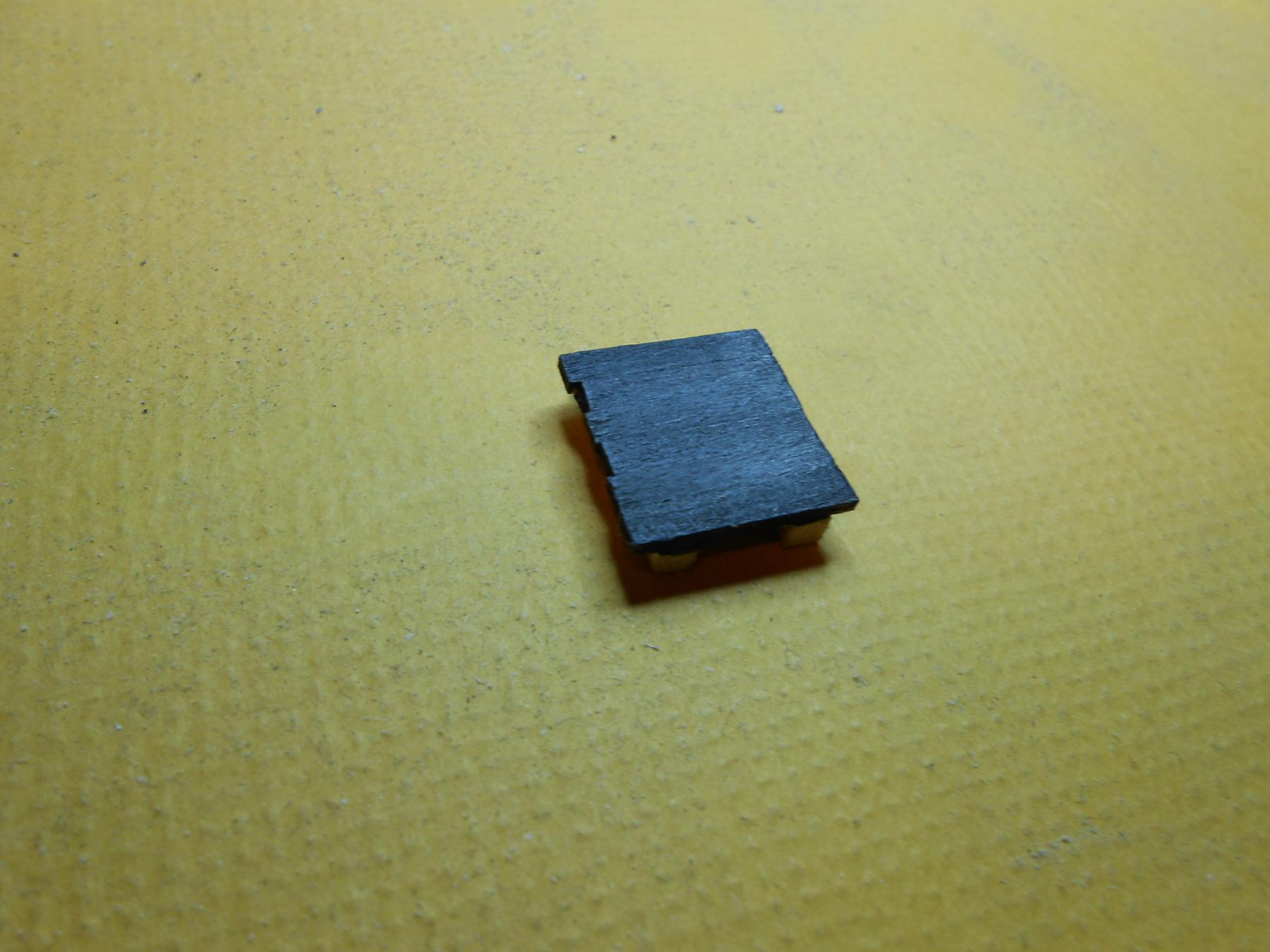
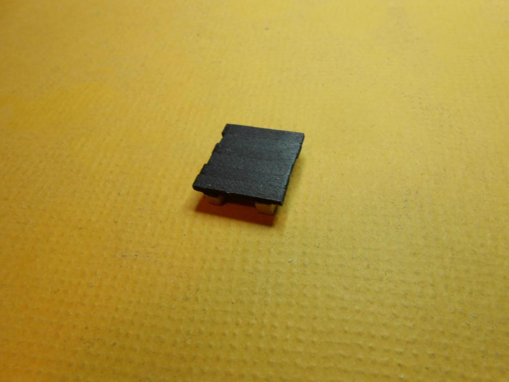
I started wondering about wood finishes a few days ago, and have been pondering whether I want to paint the hull or not. I wasn't really warm to the idea of painting it, since paint tends to fill the grain structure, and the painted pieces don't really look like wood after that. So I started thinking about stains. I have a can of Minwax ebony stain, so I thought I would try that. It looked good, but not really black... More of a very, very, very dark brown. So I ruled it out. So I prepared another test platform and tried a black Sharpie. It gave a nice black, but left shiny spots on the wood which I didn't really care for. I knew I could probably get away with this and give it a squirt of dull coat afterwards, but it still wasn't an optimal solution. So then I got the idea to try India Ink... This gave me the exact finish I was looking for. It is dead black, and gives the illusion of painted wood. Here are a couple of pictures that show the grain, and you can differentiate between the individual planks. Matt

- 117 replies
-
- 6
-
-
- constitution
- model shipways
- (and 1 more)
-
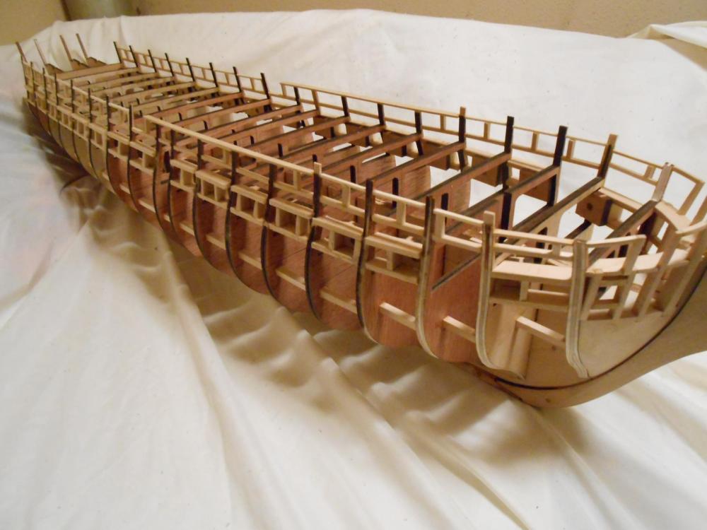
Thanks, Tom. I will have to check for bin primer as well. So here you all can see I have almost completed the front starboard quarter of gun and anchor ports, as well as part of the main rail. The only thing left to really do up here is add the strips on the outside and inside of the ports ahead of bulkhead "E", but I am going to hold off on that until I fair this potion of the hull. This allows me to just do it in a single strip instead of several short ones. As you can see by the photos, it is coming along smoothly. Getting the right bends in the main rail was a little tricky, but fairly simple. All I did was soak the plank in hot water for about 3 minutes, eye-balled the bends, and held it in front of a little space heater I have to set it. The bends are subtle, but really need to be there. If you look at the pictures, you will see it, I am sure. The moulding that I cut into the rail may not be visible though. I took a piece of scrap brass I had lying about, and cut a moulding profile into it, and then dragged the edge against it. Brass is plenty tough enough for this task on such a soft wood as basswood is. This tiny moulding will barely be seen, I know. But my philosophy of modeling is that if it looks like a model, you didn't do a great job. A model should look like the real thing, not a model of the real thing. What makes this happen relies on two things, in my opinion... The first is detail, and the second is proportion. If detail is missing, it will look like a model. If something is out of proportion, it will look like a model. Of course, workmanship is important to, but I have been fooled by models which didn't have the greatest workmanship, yet the level of detail shifted my attention from that to the point that it took me a few minutes to notice missteps in workmanship. And concerning proportion, I have discarded parts on plastic and metal kits before, like piping molded in plastic, in favor of brass wire, or fashioned my own parts from scratch. Enough of my rambling, here are the pictures:

- 117 replies
-
- 8
-
-
- constitution
- model shipways
- (and 1 more)
-
I know my updates are a bit slow, but I am new to this, so I beg everyone's patience. Today I started on the spar deck gun and anchor ports. These are a lot more fun than the gun deck boxes, though I don't know why. But these are a bit tougher to do. The wood is thin, and easily broken. My hand aren't as steady as they used to be, but they are still functioning, and should be capable of doing the job. To think at one time I was going to become a surgeon... lol. Anyway, this is the beginning of the spar deck gun ports. It is going to storm tomorrow, so I should be able to get some work done. I still haven't glued in the gun deck boxes, since that can throw off the top gun port positions. I know that in the pics I have those in there, but just to show the relationships between the two decks. As I am seeing it, the lower gun deck is slightly more flat than the spar deck. It may be an illusion, but that is what I see. I will need to check it against my AOTS book. Matt

- 117 replies
-
- 6
-
-
- constitution
- model shipways
- (and 1 more)
-
You are doing a fine and admirable job, Elijah... Keep up the great work! Matt
- 701 replies
-
- 4
-
-
- phantom
- model shipways
- (and 1 more)
-
Thanks, David. I will look into that. I also considered an etching automotive primer, which I am pretty sure would have done the job nicely, but I am out right now, and it is kind of pricey at $30 USD for a regular aerosol can. I will look for the camo coat though. Matt
- 117 replies
-
- 1
-
-
- constitution
- model shipways
- (and 1 more)