Srodbro
-
Posts
299 -
Joined
-
Last visited
Content Type
Profiles
Forums
Gallery
Events
Everything posted by Srodbro
-
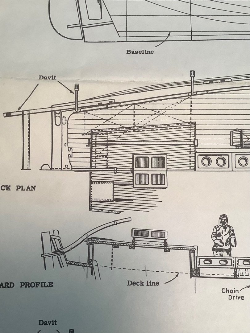
I have only just discovered you build log, but will follow closely as I am building the Model Shipways kit version of Gjoa. If I may ask: Have you any opinion on where one would stand to steer this vessel? Below is a pic of the kit instructions showing the tiller, and a scaled crew. I don’t imagine one would climb atop the cabin. The plan you show in your log seems to indicate lines from the tiller end to the corners of the cabin. Even using those lines, it seems to me there isn’t a good place to stand to efficiently reach them.
-
Makes you wonder at how six guys could jump on top of all that stuff in a pitching sea and get sorted and shoved off from the ship, and still be able to successfully chase a whale.
- 200 replies
-
- 2
-

-
- Whaling Bark
- Charles W Morgan
- (and 1 more)
-
Nearly all my models have been solid hull. I don’t have anything against POB, I just never got the hang of doing a good job with plank on bulkhead. I don’t think you sacrifice accuracy either way. Several of my models (Niagara, Chas Morgan) started from kits that I used the drawings to create patterns for bread and butter hulls, which I then planked. Others ( Kate Cory, three versions of Dapper Tom, and Gjoa) I used the solid hull from the kit as a base to apply planking to. Unlike plank on bulkhead, I have an infinite number of locations to attach a plank. Also, I have better luck getting planks to conform to odd curves. Also, glitches in shaping a hull can to me be easily corrected by cutting out and inserting a new hunk of wood and reshaping ( and filling, and sanding, maybe ad nasium). Attachment points for cleats, eyebolts, channels and even mast holes seem to me much more secure, as well. I will admit the method presents a bunch of its own challenges. The half hull I did on Wyoming at 1/8”/ft was a pretty heavy log that required a custom mount to the workbench to facilitate using planes and rasps during shaping. And, repeatedly adding station lines and waterlines while shaping can become tedious after awhile. I really love those old yellow-box solid hull kits. I’ll miss ‘em.
-
If it looks right to you, then it’s right. One could easily argue ( if needed) that your choice actually is the scaled color, that the “ real” color is much darker than your choice, since lighter-darker are relative terms, and there is probably no baseline to measure against. Not sure how anyone could be definitive with a ship of fiction. Looks great to me.
- 346 replies
-
- 3
-
-
- Sophie
- Vanguard Models
- (and 1 more)
-
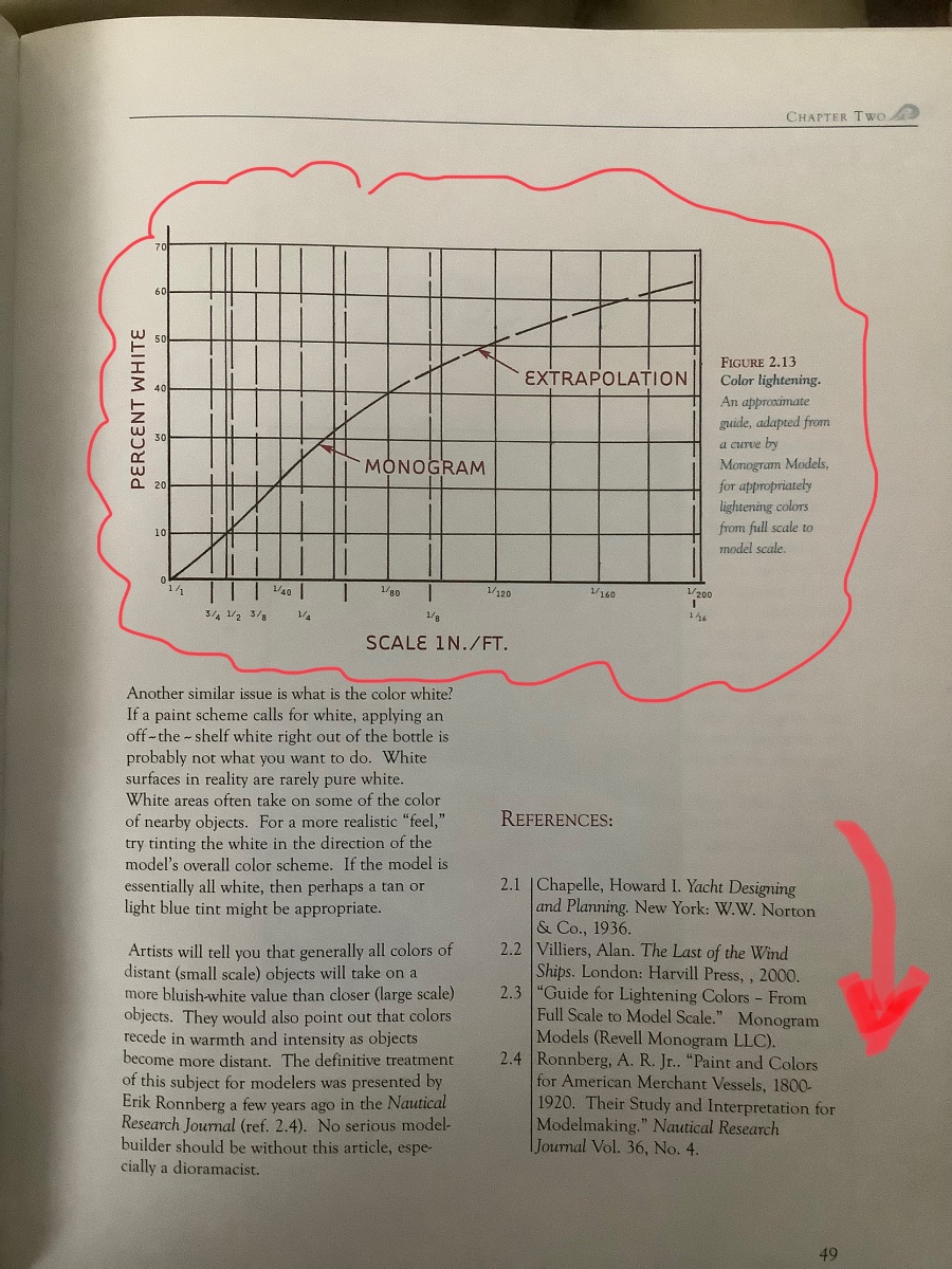
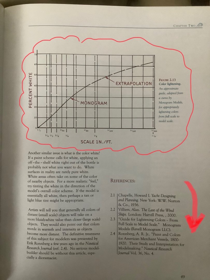
Further to Flyer’s comment on color scale: Justin Camarata addresses this in his book, Waterline Dioramas. He references a chart created by Monogram Models that indicates the % white to be added to any color, including black, to get “ scaled color”. He also references an article by Eric Ronnberg in a past NRG Journal that addresses this (perhaps another NRG member can comment on that article … I’ve not seen it). Here’s a pic of the page from Camarata’s book:
- 346 replies
-
- 6
-

-
-

-
- Sophie
- Vanguard Models
- (and 1 more)
-
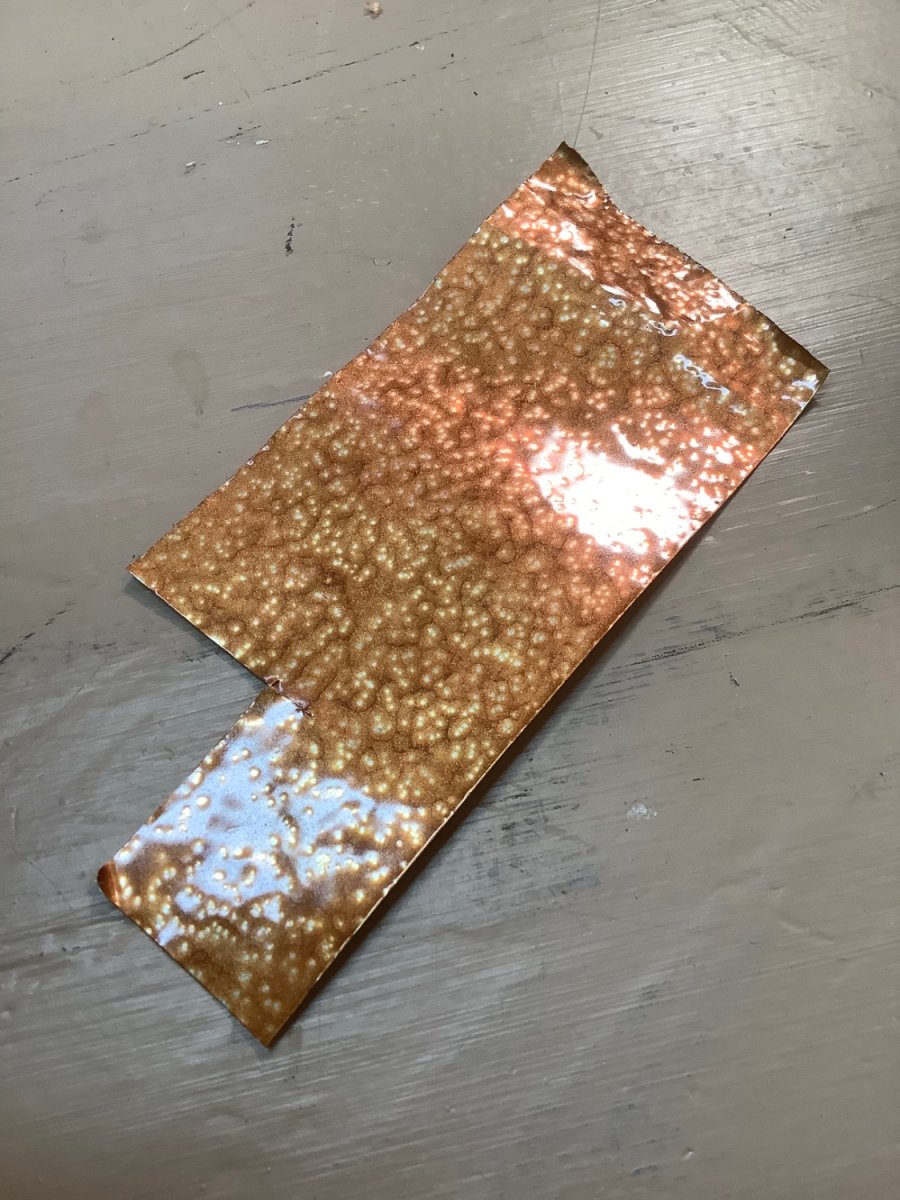
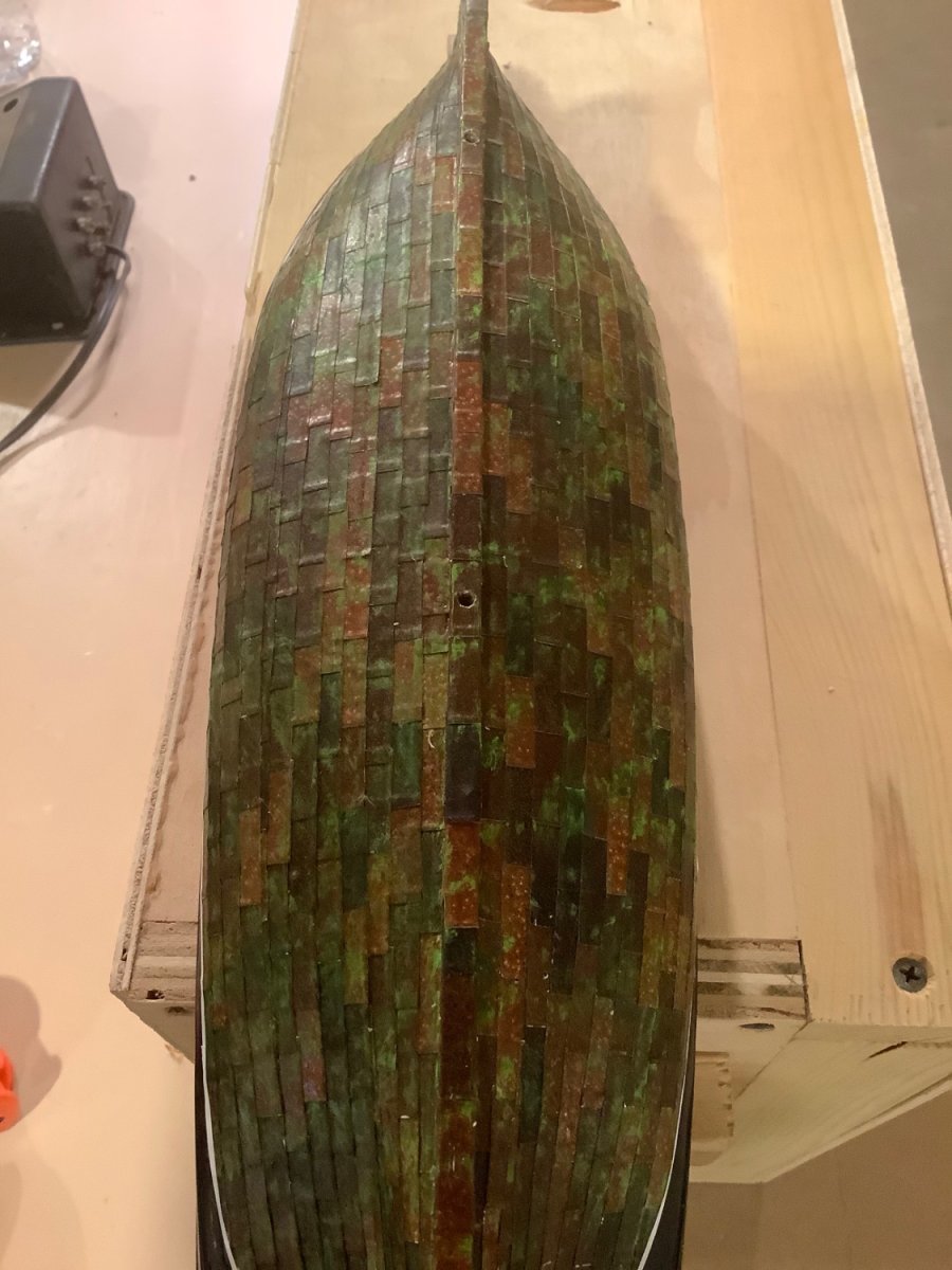
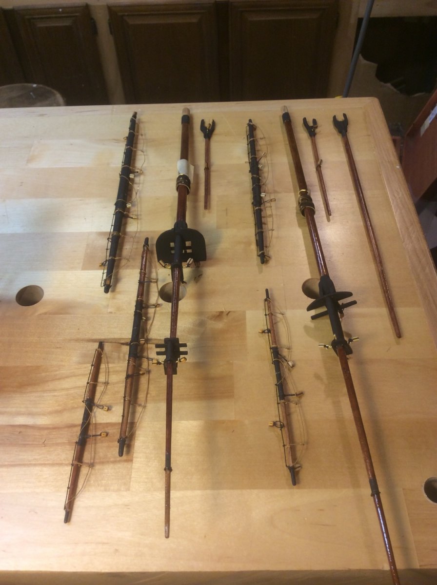
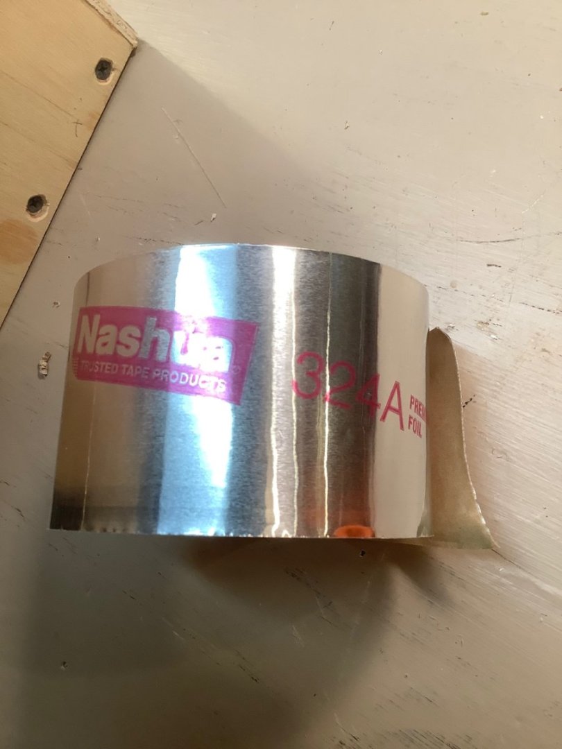
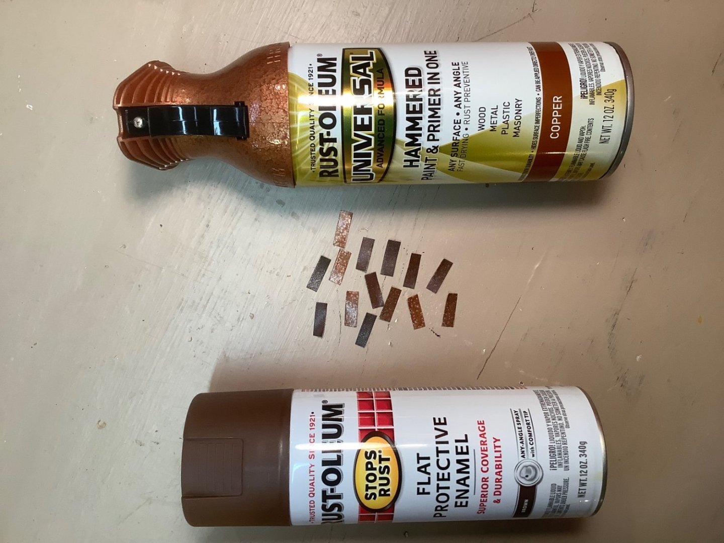
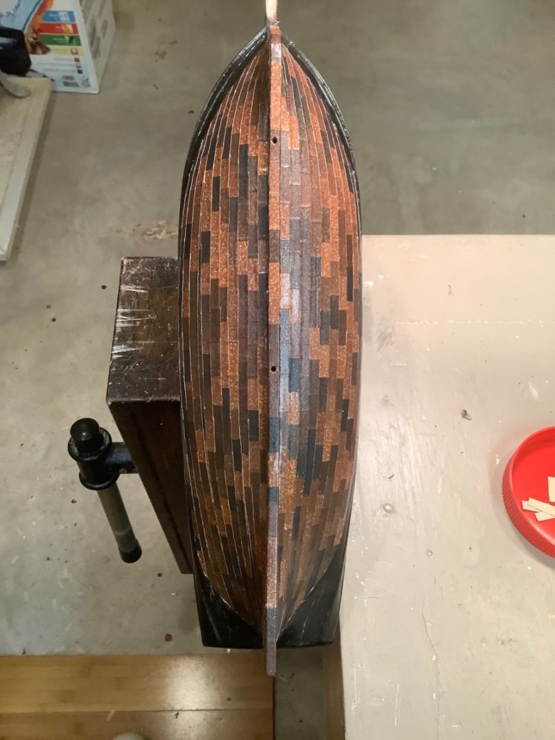
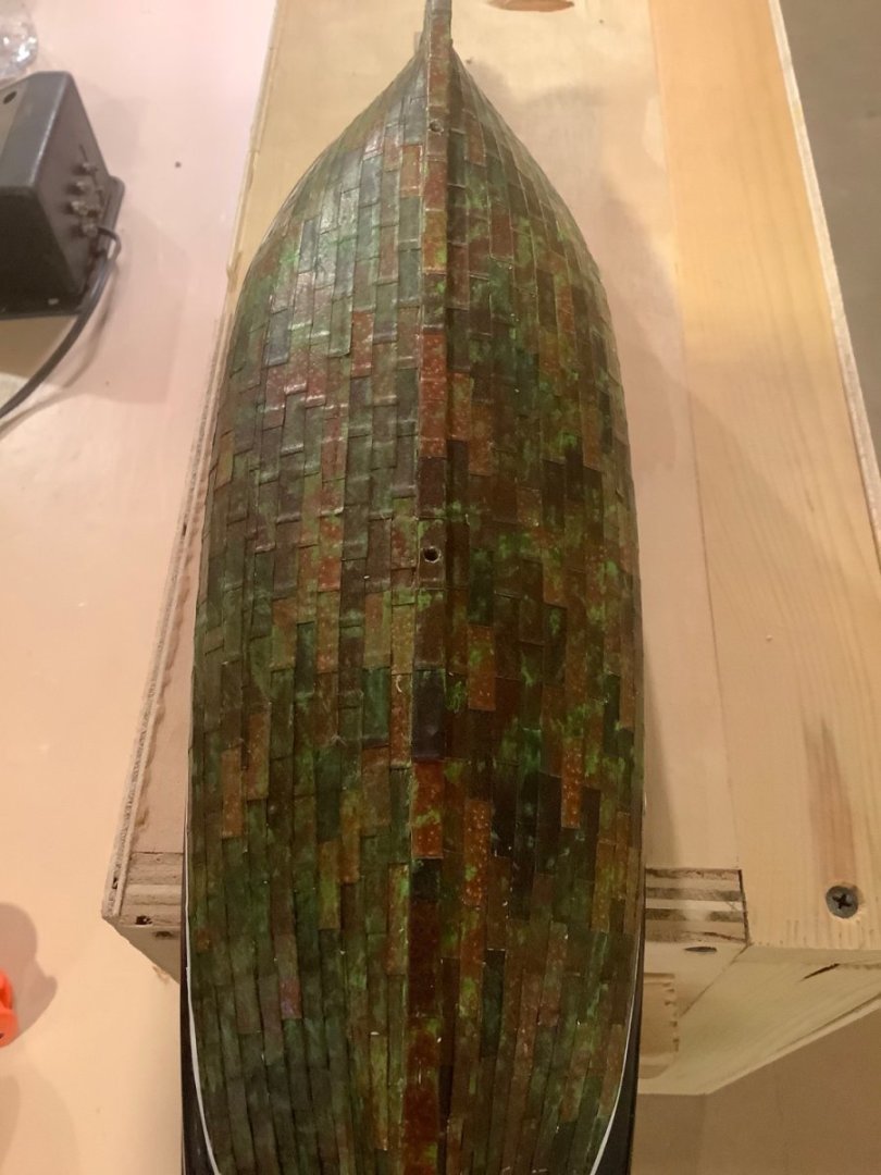
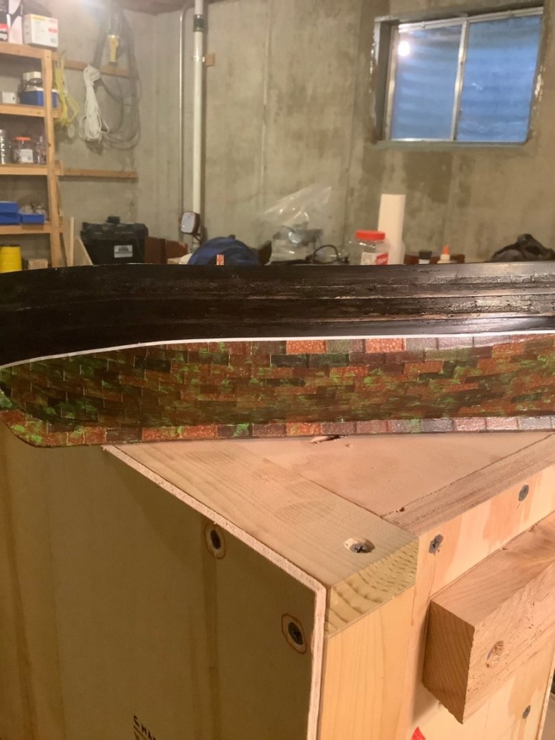
Dave: All the advice given by those experienced expert modelers above is really good stuff. At the risk of ruffling modeling sensitivities, I offer an alternative that is satisfactory to me, while admitting that I readily trespass on scaling and coloring guidelines, to get the effect I like. Perhaps only the product information might be useful. I used a foil tape product generally used for sealing the seams of foil-backed insulation ( clearly much thicker than scale). I painted several strips of this stuff with a “ hammered copper” spray paint, then gave a dust coating of flat brown, of varying density. I cut the tape to the copper cladding sheet size I wanted ( probably larger than scale) then selected individual tiles at random and applied to the hull. Finally, I dappled on with a nearly dry brush some green patina, Testors “ sublime green”. Here are the products used: Bottom pic is of the painted tape, without the flat brown dusting. Top pic includes several of the cut cladding tiles. Here is the clad hull, prior to green weathering. Here it is with green added. Of course, nobody will ever see the hull from this angle, so here’s an idea of how it looks from the side. I try to represent my models as working ships, weathered, abused and beaten, especially if it is a whaler ( as this one is), rather than pristine, perfect museum exhibits. I have been at working waterfronts, and at ports where recreations and replicas are displayed, and there is clearly a difference in the respective appearances. You have to model what you like ( unless you are getting paid for it) Like I said, just another alternative.

- 44 replies
-
- 11
-
-
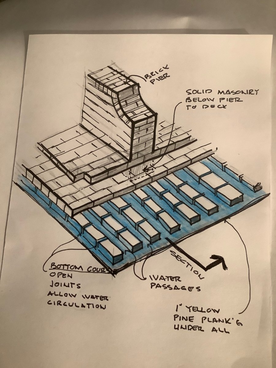
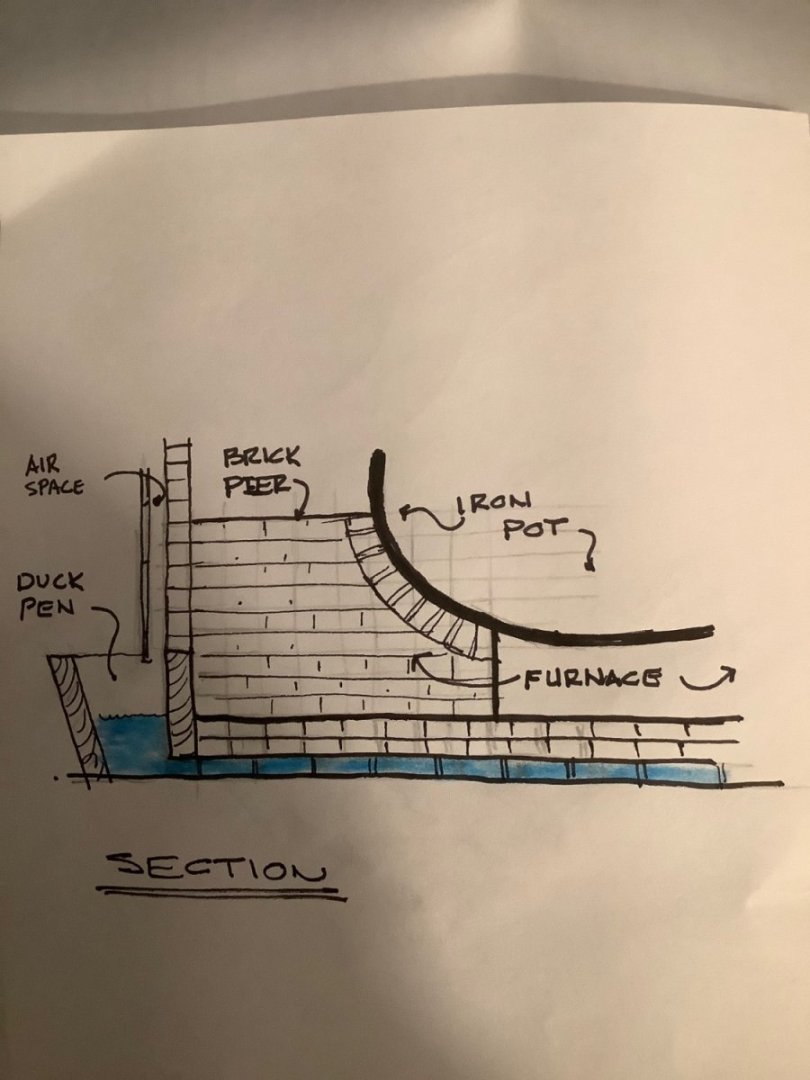
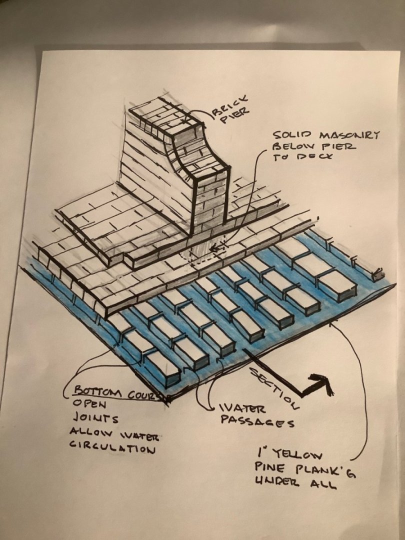
Mystery Solved ! I obtained from Mystic Seaport Museum a drawing of the try works construction details. Here are a couple ( very rough) sketches that describe the construction shown on the drawings. The bottom course of brick rests on a layer of yellow pine sheathing over the deck. This course has open joints with no mortar between. Several courses with mortar joints lay on top of the base course, and form the floor of the furnace. In several locations, brick piers are built up to where the iron pots can rest on them. I suspect ( but this isn’t clear from the construction drawings) that these piers extend all the way down to the sheathing, penetrating the water course. In the sketch the blue represents the water “ coolant “ that provides additional protection to the deck. Filled at the “duck pen” the water level could be kept high enough there to assure flow thru the bottom course interstices. The next sketch shows additional detail The bricks of the bottom water course are widely spaced athwart ships to provide even more water protection. This whole try works structure would have been enormously heavy. There is a wooden plank structure with massive iron brackets fastened to the deck on the starboard and port sides of the structure to hold it in place, but it doesn’t seem there is much to keep it from sliding fore-aft … but apparently the weight was enough. Nonetheless, the working of the ship must have played havoc with the integrity of the joints. Seeing this construction, I wonder whether the water course was less intended to protect the deck from heat than from fat/grease leaking thru the layers of brick ( due to cracks in the masonry and joints ) from the burning of blubber scraps as fuel and spreading fire to the deck below. At any rate, the arrangement of this water course and the structure supporting the pots is more clear.
-
Regarding Post #10 & #11: Might early black “ tar” have been used on hulls primarily to deter deterioration by those nasty salt water worms that eat wood?
-
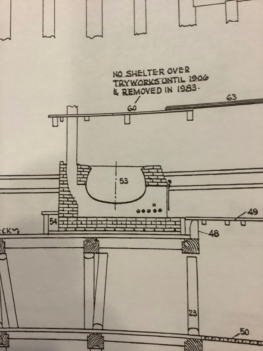
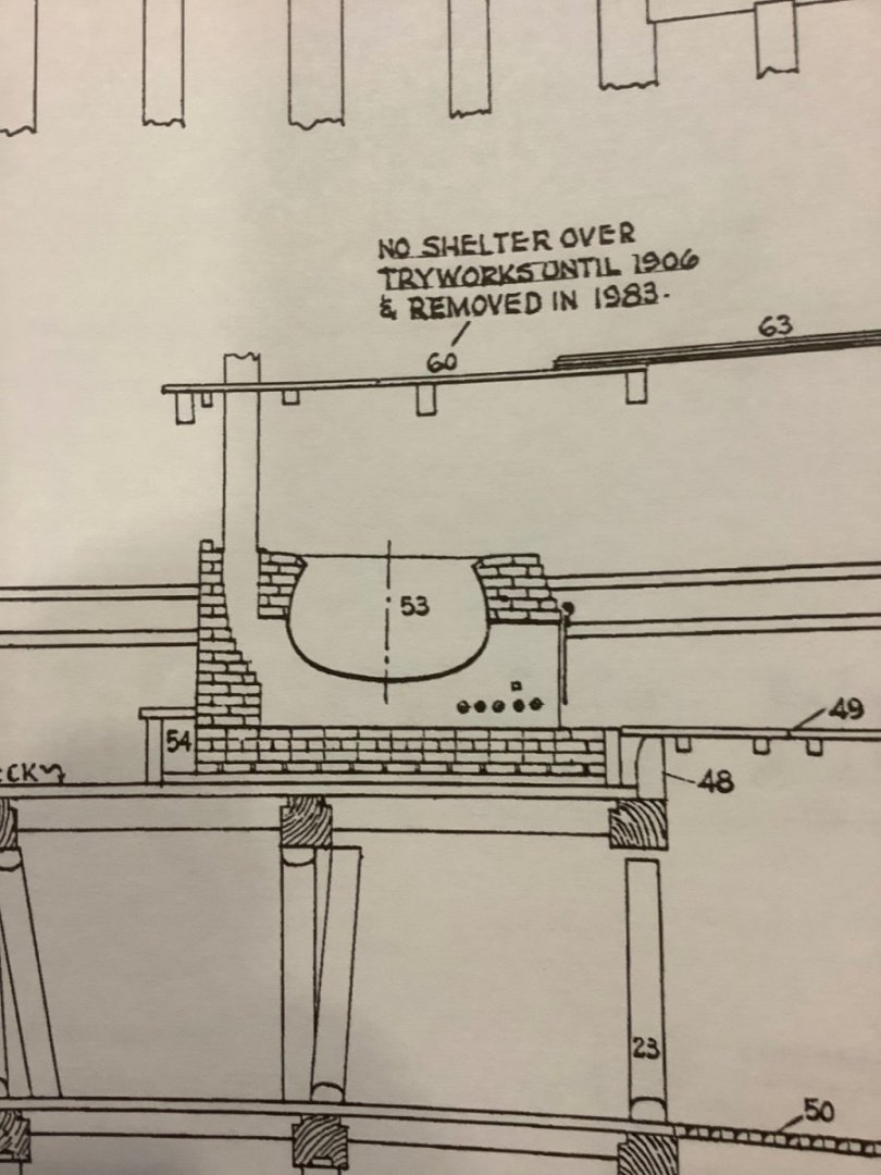
Thanks for the reminder. Upon further search of their website, it appears that they have a separate detail drawing of the tryworks construction. I have a set of Morgan plans purchased from them, but the particular detail I’m looking for is not included. I will contact them. Below is a copy of the section thru the tryworks on those plans. Not much help in describing the relationship between the pots/masonry/deck. However, the lowest course of bricks curiously shows conspicuously large joints between the bricks of that course. Perhaps this is to allow water retention at the bottom? We will see what the additional detail shows. I’ll update this post then.
-
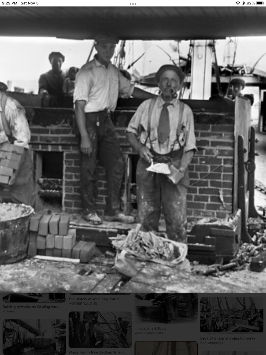
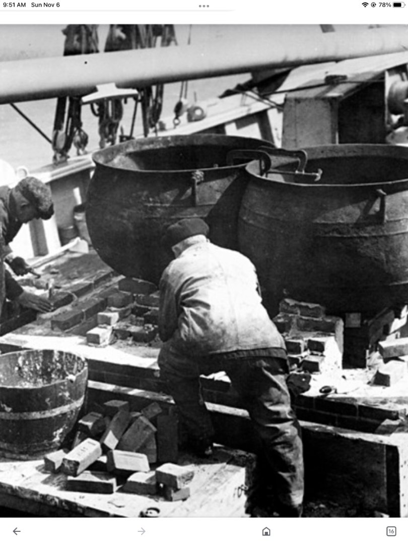
I’m working on a couple of model whale ships and have a question about the construction of the Try-works. I have read that the furnace below the pots enclosed by the brick masonry was separated from the ships structure by a water-filled “duck pen”. Wiki says “A reservoir of water under the bricks keeps the furnace from scorching the wood of the deck. I’m having a hard time visualizing how this worked. In these pics from the web, there is clearly a substantial masonry structure supporting the pots and the lid. And while the fire in the furnace might not have had to be a blaze like in a smelter (I think the blubber probably released its oil at relatively low temperatures, like 150°), the trying out process lasted for days, so the ships structure certainly needed protection from the heat. Iron pots that big had to weigh several hundred lbs plus the weight of the blubbery contents. The masonry support must also have been complemented by some internal baffles to get the heat all around the pots, and back to the chimney. So, where is this layer of protective water? In the lower pic, I can imagine that the wooden structure below the fellow’s knee could be a water tank. But, if so, how was all that masonry and the weight of the pots supported above it?

-
Work bench width and height - any recommendations?
Srodbro replied to Dr PR's topic in Modeling tools and Workshop Equipment
Don’t forget to obtain a building permit. Workshops are famous focal points for “ home inspectors” and code enforcement officials, which could affect your ability to sell the property some day. -
Work bench width and height - any recommendations?
Srodbro replied to Dr PR's topic in Modeling tools and Workshop Equipment
All excellent suggestions. I’d add a couple more regarding electrical: In lieu of duplex receptacles install quadruplex … seems like wherever you put them, you always need one more to avoid plugging/unplugging frequently. Also, consider a couple mounted at ceiling … you gotta do wiring for lights up there anyway, and having the outlet above is another way to avoid dragging the cord across the bench. Finally, if this is an addition, presumably there is a new floor. Consider running power under the floor to a recessed utility box with outlets (maybe even a compressed air terminal) in it. Ok, one other thing: Consider something to keep your feet comfortable while standing. I have a 3’x4’ glued-up section of 3/4” thick T&G flooring to stand on at the workbench ( but not while feeding my table saw) … softer and warmer than concrete. Heck … this is fun: spending your money! -
Work bench width and height - any recommendations?
Srodbro replied to Dr PR's topic in Modeling tools and Workshop Equipment
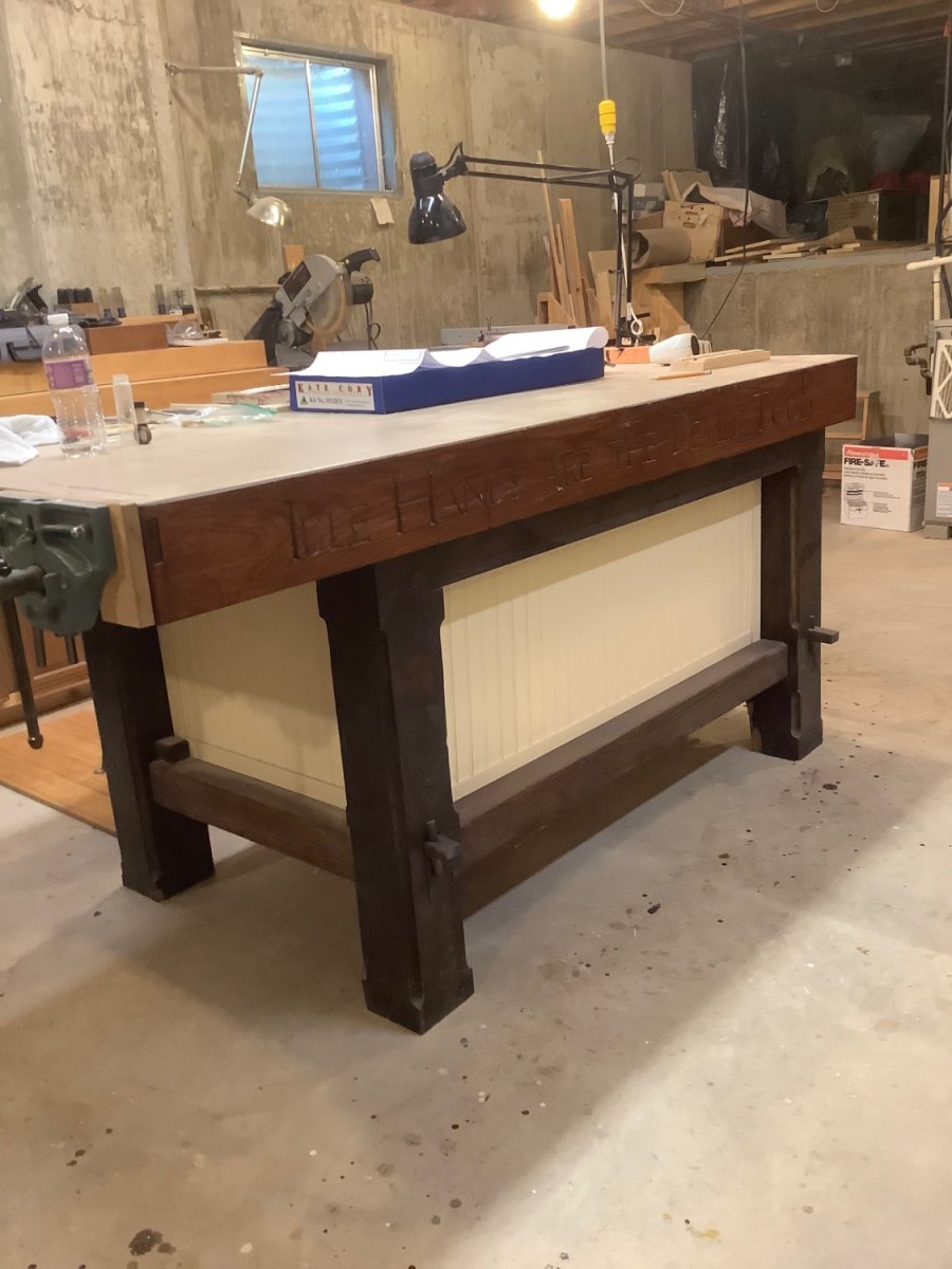
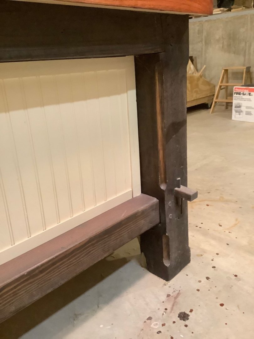
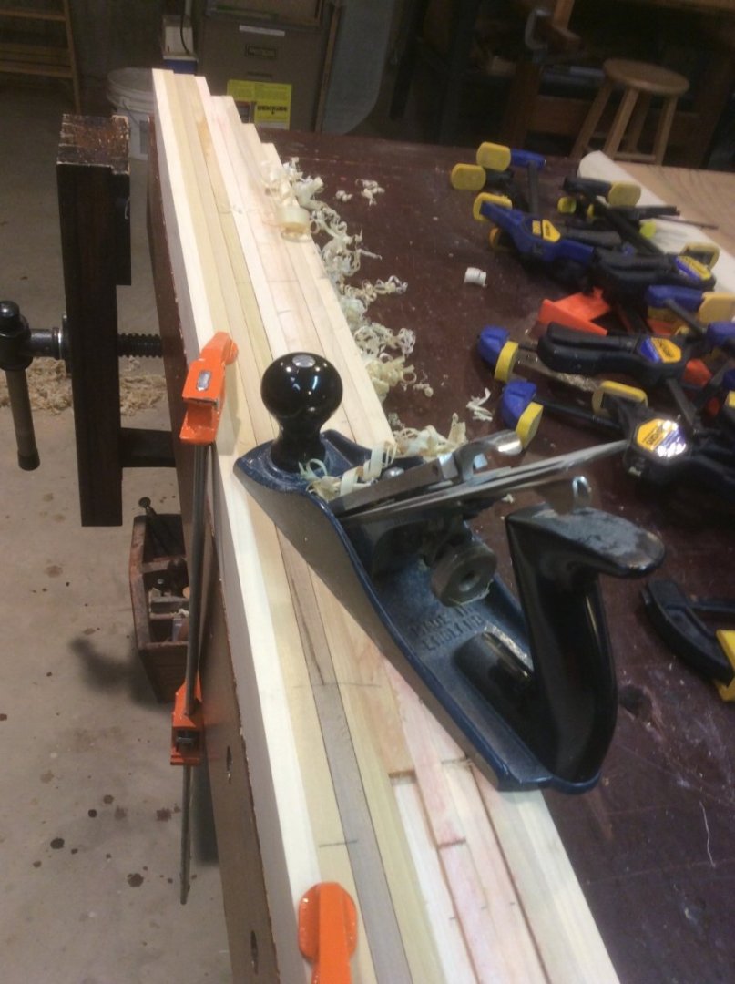
I highly recommend this book as a great guide to deciding what works for you, whether a fine piece of woodworking, or a true WORKbench. You don’t mention if you are contemplating a freestanding bench or a wall bench. My freestanding bench is roughly 3ft by 6 ft, and stands about 39” high. The height was determined by the height of my table saw ( my bench servers as an extended runout) and the runout of my power miter saw, the complementary heights having been useful at times. The other characteristic I’d highly recommend is build it really ROBUST! Mine is made of pressure treated 6x6’s and 4x4’s. The top is a series of laminated 2x4’s, with a 1x6 oak skirt run around the top. With the exception of the top ( which has three threaded steel rod running thru the laminations), all joinery is held together by mortise and tenon and half dovetail joints, wooden pegs and wedges. Pressure treated lumber is 50% heavier than kiln dried, and shrinks very little. The bench is heavy, and without being bolted down, doesn’t move. I generally build solid hull models, several have been large half-hulls, and when attacking a stack of glued together laminations with planes, rasps, gouges and chisels it is nice to have all your effort go thru the tool and into the wood, and not into moving the bench or fighting wobbly joints. As mine is a WORKbench and not furniture, I don’t hesitate cutting right into the top, or drilling holes into it to secure a piece or an auxiliary light source … I fill and refinish the top every couple of years. While I love my shop, I envy anyone who is setting up a new one.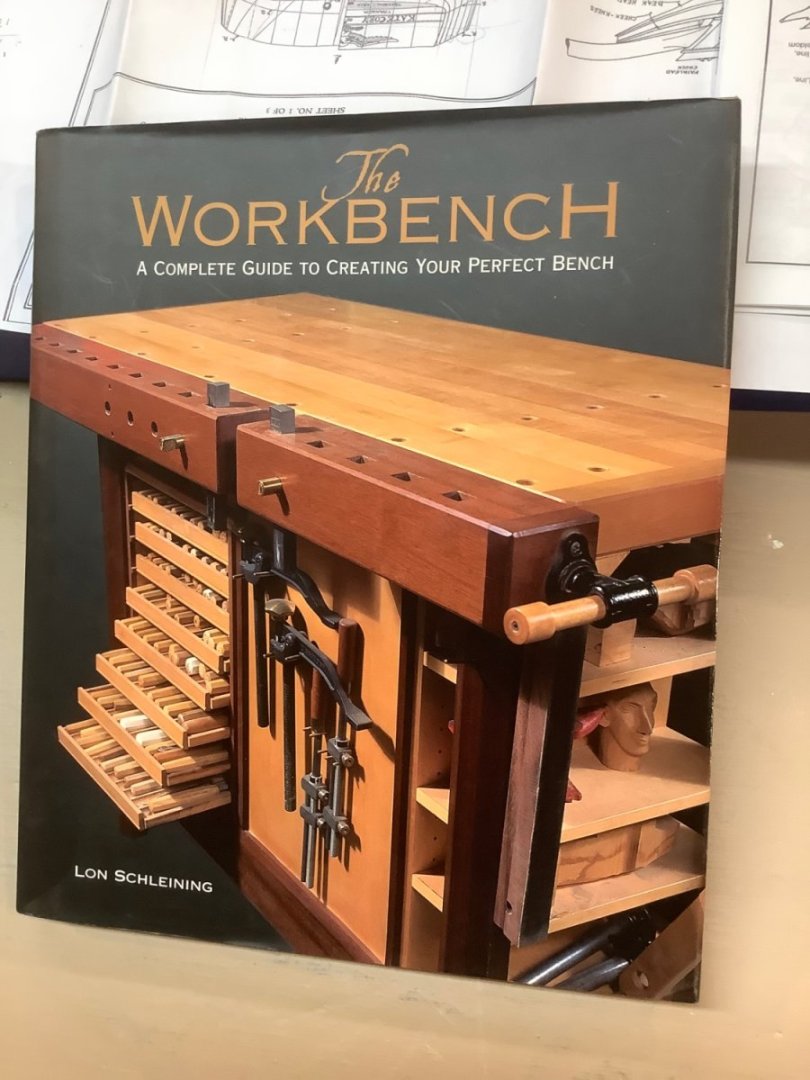

-
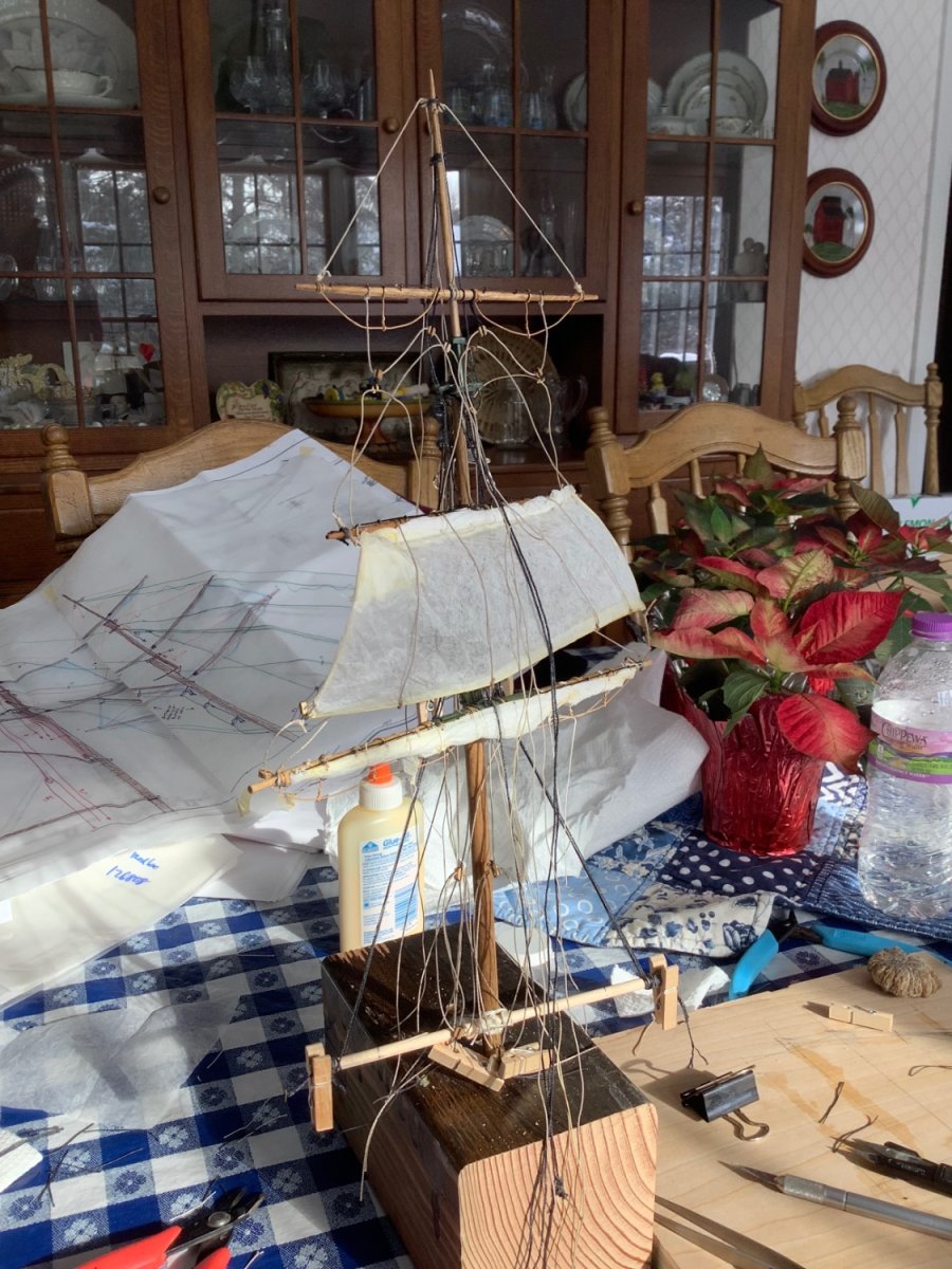
Mark: My vote would be for rigging off-model as much as possible. I tried it on my last model, and liked it. However, on my next build I’m going to rig everything from topmast up separately from the lower mast and yard, to keep a lot of the clutter from above out of the way for as long as possible. Also, I’d wait until the very end to add the ratlines for the lower mast shrouds … keeps open space for accessing the fife rail and pinrails to secure lines from above

-
Whaler copper weathering
Srodbro replied to Srodbro's topic in Painting, finishing and weathering products and techniques
Dvm27: Thanks for that video link. Breathtaking! -
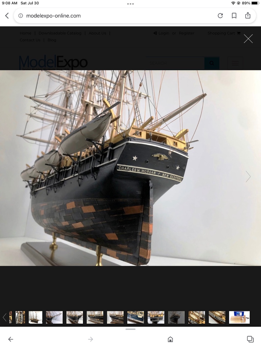
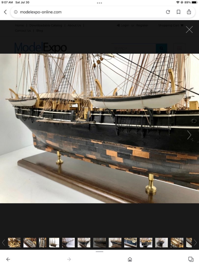
I am currently building Kate Cory and Chas Morgan. I’ve read many of the posts on copper weathering, but have a specific question. The pic below is from ModelExpo catalog of Morgan. I really like the look of this copper hull. I don’t think this model is, however, from the kit … maybe a prototype. Certainly not the copper tape included in the kit. My question: Does anyone know what the coppering/weathering technique on this model is? Or, any guesses? Thanks.

-
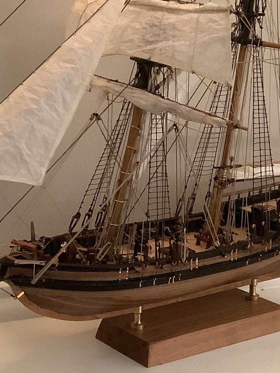
Here is what I did. 1 If no sail, then no buntlines. If sail is furled, then run buntlines to belaying point. 2. On Fore Topgallent yard with no sail, attached block for clew to sheet ( here, Topgallent yard is in lowered position, while Topsail yard is partly lowered for reefing). 3. At lower course, with furled sail ( although I think same could be done on bare yard) attach together clew, sheet and tack. Distance from yard/boomkins would be whatever looks good to you, but on mine the clew is buried up in the sail) 4. If no headsails, I just eliminated the halyard, downhaul and sheets on this model, but have hooked them all together on another, similar to the clew-sheet-tack on a square sail. All the details of my rigging may not be entirely correct (the upper block for the Fore Topgallent clew should certainly be closer to the yard) but I take artistic license on my models, for my own enjoyment.

- 63 replies
-
- 1
-
-
- Dapper Tom
- Model Shipways
- (and 1 more)
-
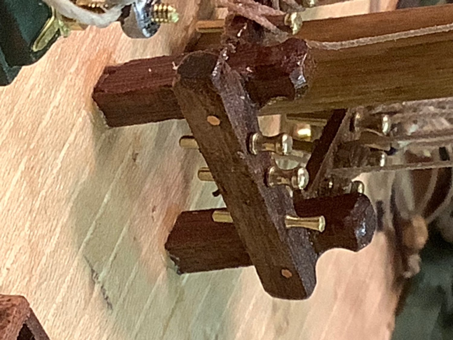
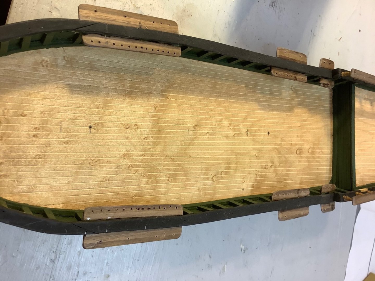
Viking ship rigging ... What’s this called
Srodbro replied to Srodbro's topic in Masting, rigging and sails
ANSWERED! I knew someone out there would eventually reveal its name. In NRG Journal, Vol. 67, No. 2, page 164, it is named as an Angel Cleat, (presumably the two “ wings” calling to mind an angel. Thanks to Clayton Feldman for his articles on building a model of Skuldelev 3. -
This thread may be a good reference to respond to your #43 post.
- 63 replies
-
- 1
-
-
- Dapper Tom
- Model Shipways
- (and 1 more)
-
Just a thought … If using the dowel-in-drill chuck method, be prudent about your drill RPM. High RPM increases risk of snapping off the spar, perhaps with injurious results ( to the spar and drill operator) especially on thin spars. More so the longer the spar is.
-
Probably can’t go wrong with basic black. Images of Pride of Baltimore I and II seem to show black. I don’t think there is any standard. I think whatever turns you on. And even tho they say to never, ever use glossy finish ( flats only), sometimes I kinda like a bit of sheen on my spars. I’ve done black, white, green and gray with clear or natural on the unpainted portion.


-
Very nice work.
-
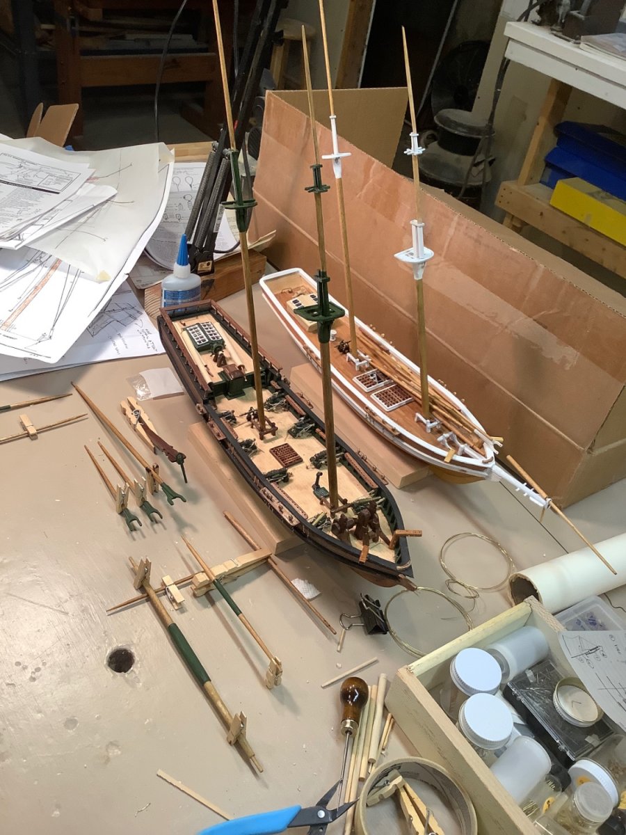
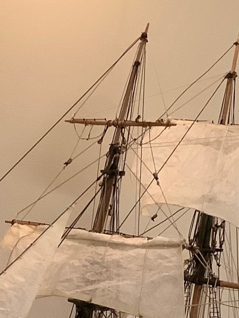
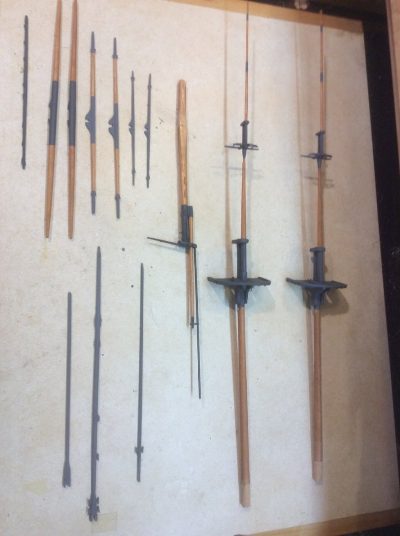
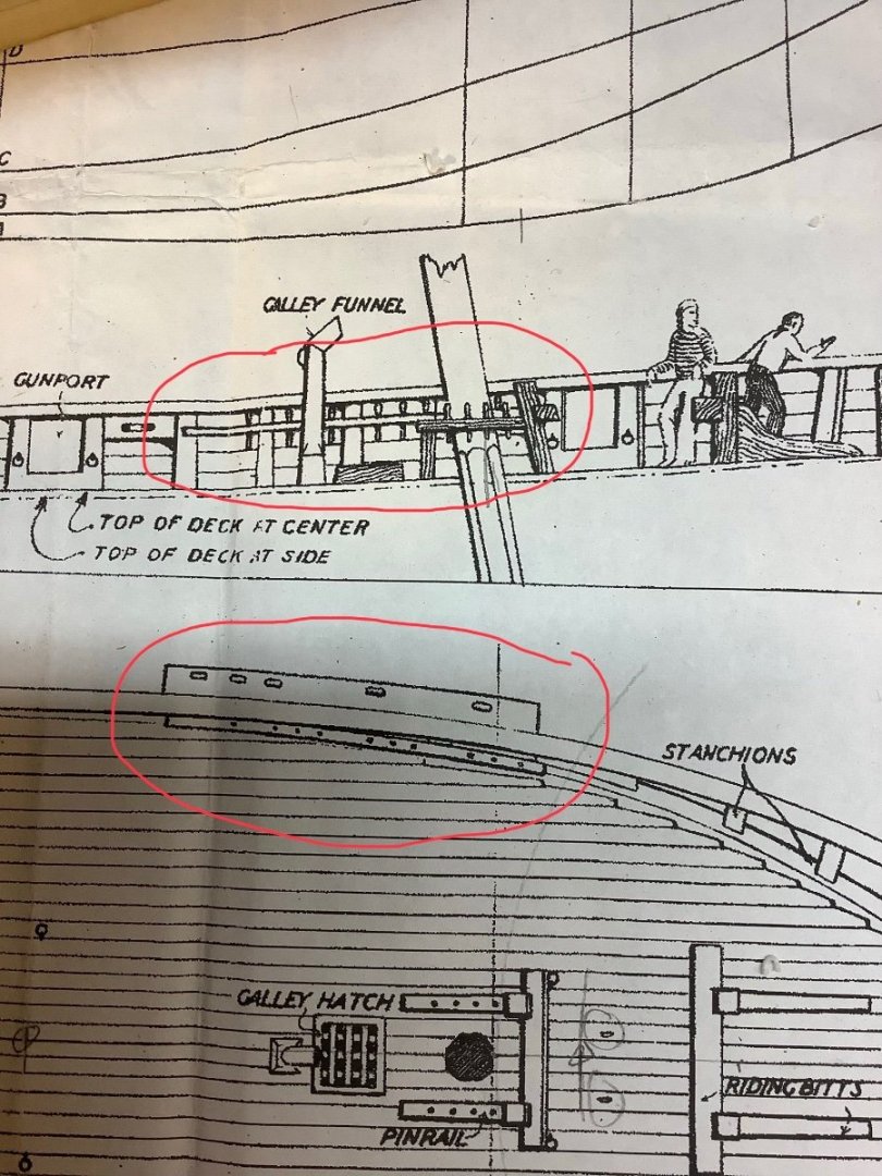
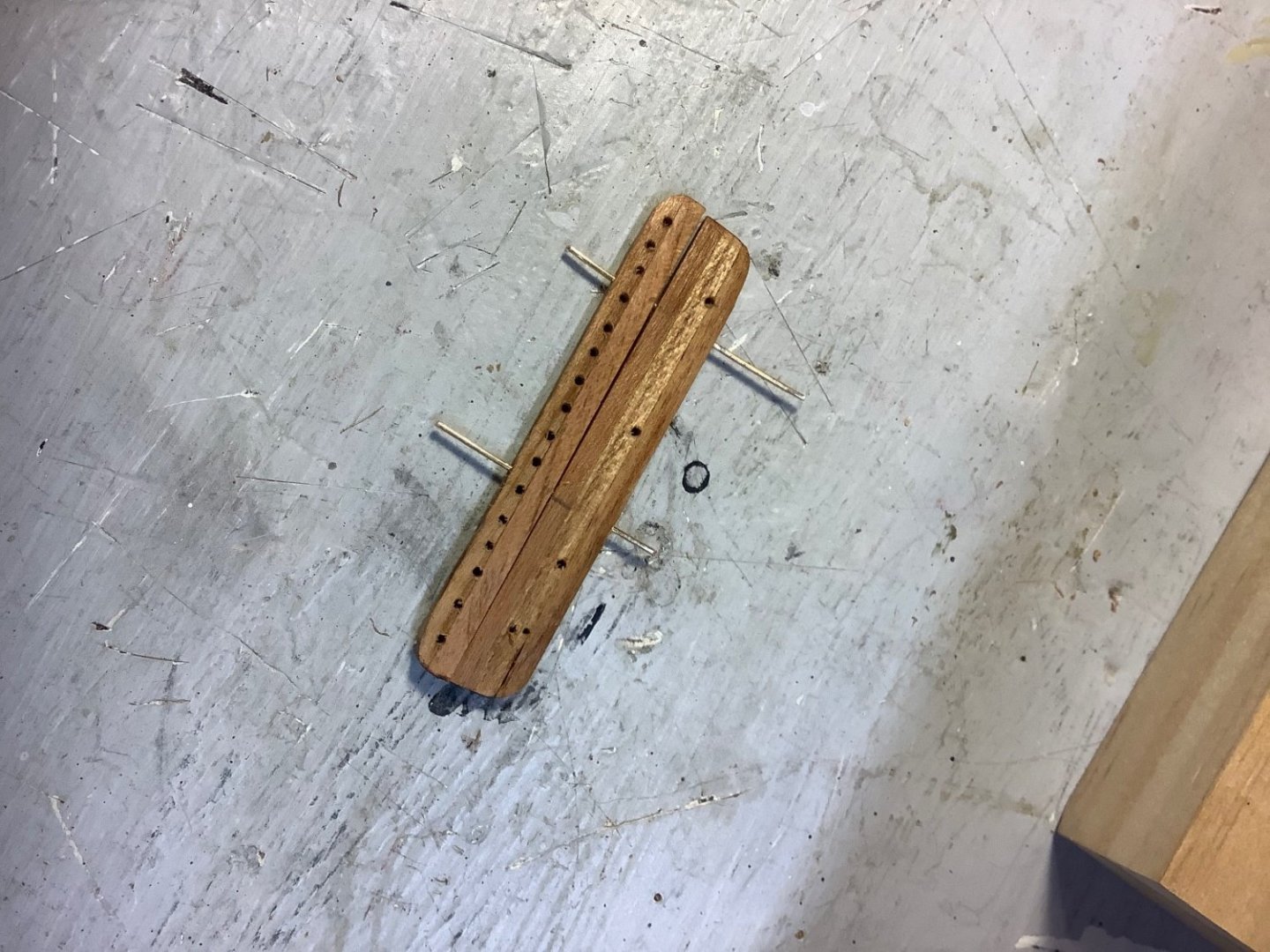
Your build is really looking good. Very, very nice. Just a comment on channels and pinrails. On Dapper Tom, the length and mounting height of the channels and pinrails are just about equal, and almost exactly opposite each other below the rail. I found to my chagrin on past models that when I eventually get to rigging shrouds and belaying lines from above that the channels and pinrails invariably are weak points that break when I hunker down on the lanyards, or insert a belaying pin into a just-a-bit too tight hole ( I’m probably just too heavy handed for this work). So, I now make a point of reinforcing those elements with a piece of brass wire run thru each. I reinforce at the fife rails, as well. Just a thought. Those things are really inconvenient to fix while rigging. ( Sorry … not sure why pics got rotated).

- 63 replies
-
- 2
-
-
- Dapper Tom
- Model Shipways
- (and 1 more)