HOLIDAY DONATION DRIVE - SUPPORT MSW - DO YOUR PART TO KEEP THIS GREAT FORUM GOING! (Only 20 donations so far - C'mon guys!)
×


Srodbro
-
Posts
299 -
Joined
-
Last visited
Content Type
Profiles
Forums
Gallery
Events
Everything posted by Srodbro
-
Bob Cleek: ”Acoating of white shellac is an excellent sealer for model parts.” When would one apply the shellac? Must be after planking, since we need moisture in the planks to form to the hull ( less so for a deck). But, If after planking, which is after adding blocking between ribs, how does sealer get to the underside of the plank? The blocking should be coated as well, before planking? Or, is the idea that you seal as much as you can , and continue to hope?
-
Jack: regarding rigging ... I found this an invaluable reference when I built my Fra Berlanga refrigerated ship FM 55-17 Chapter 3, Ships Gear and Rigging Procedures https://www.globalsecurity.org/military/library/policy/army/fm/55-17/ch3.htm
- 106 replies
-
- 8
-

-
- trumpeter
- john brown
- (and 2 more)
-
Old model shipways USS essex (solid hull)
Srodbro replied to Mike Esposito's topic in Wood ship model kits
I agree with all said above, especially if you’re new to modeling ... incomplete kits can be very frustrating. But I’ll offer one exception that the old kits provided that newer ones don’t: Some of the old kits had solid hulls made of really good wood .. very dense, straight grain a pleasure to work with hand tools. Not sure if it was old growth pine or southern yellow pine, but was really nice stuff. Found two Dapper Tom kits on eBay from late ‘50s early ‘60s. The rest of the wood was pretty much junk (warped dowels, splintery planks) and castings with white powder corrosion product on them, and discolored and rotting rigging thread. So, I too would stay away from “vintage” kits, unless trying to win the lottery and find a solid hull that can take a beautiful finish. -
Joe: Can you say where your illustration comes from? Does it have accompanying text? Grandpa was a blacksmith, and I think there are a couple pieces of iron shaped like those in the pic deep down in the cellar. A reference might help me identify them. Thanks.
-
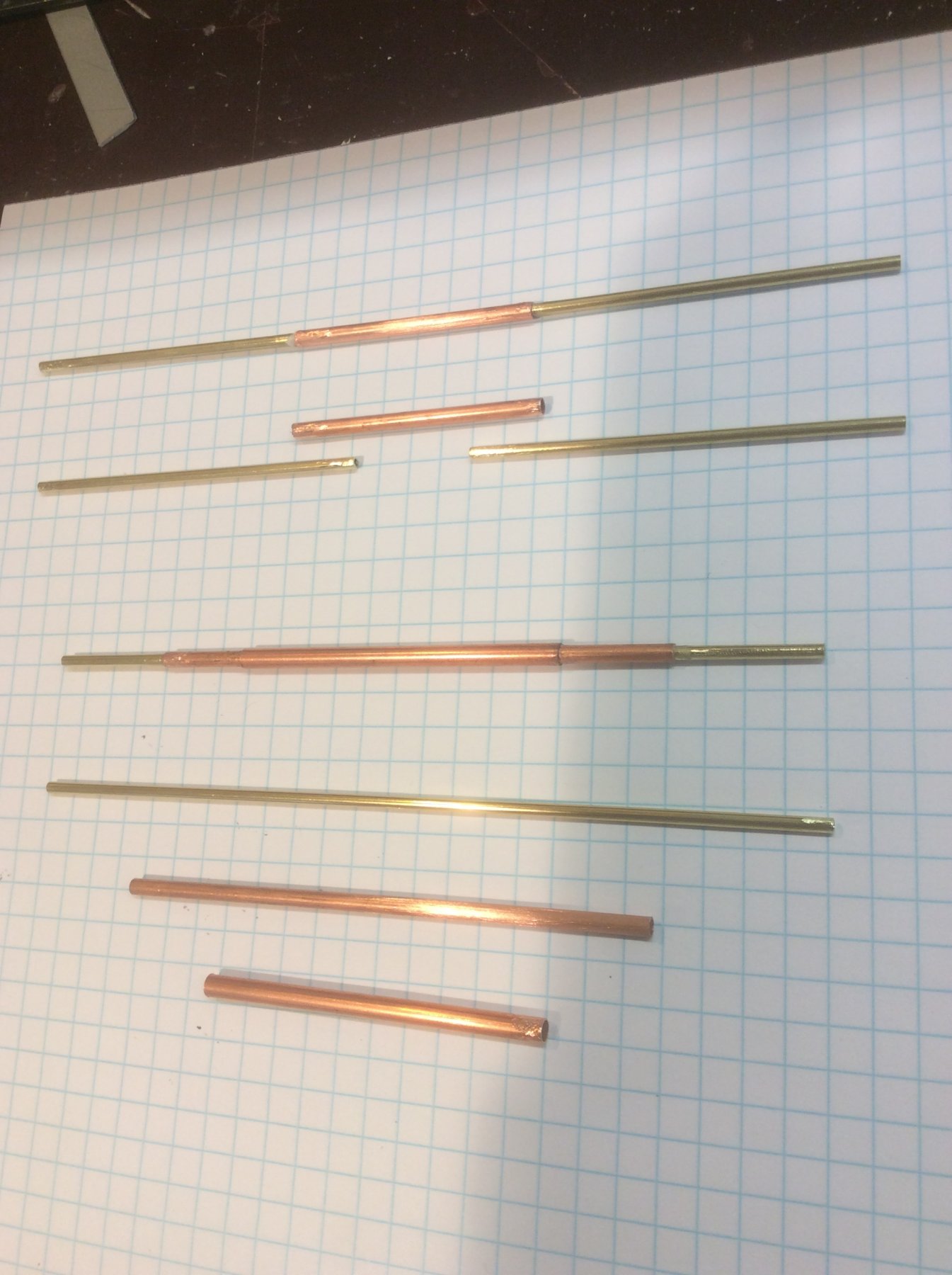
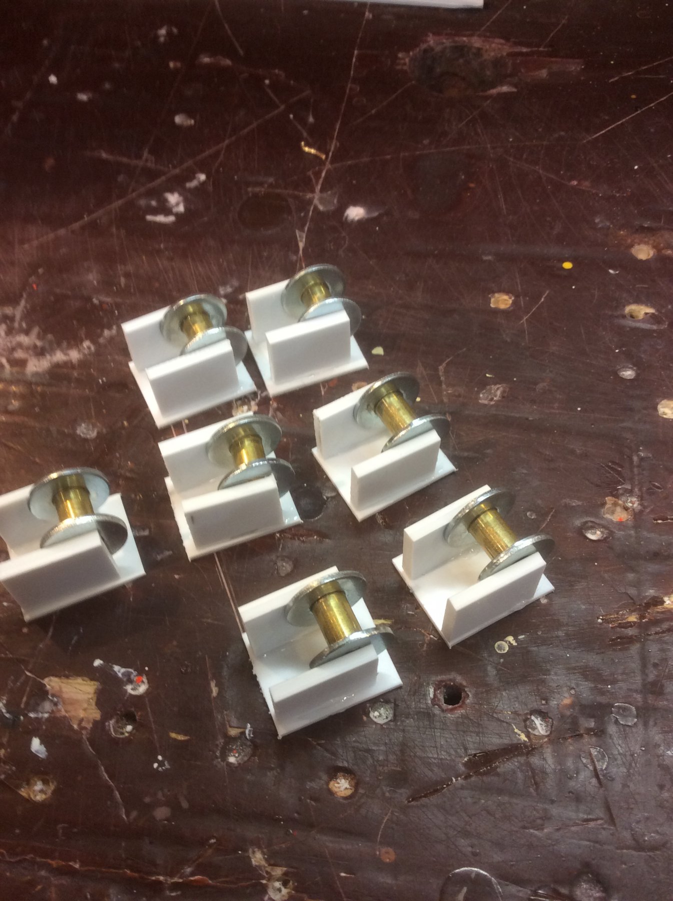
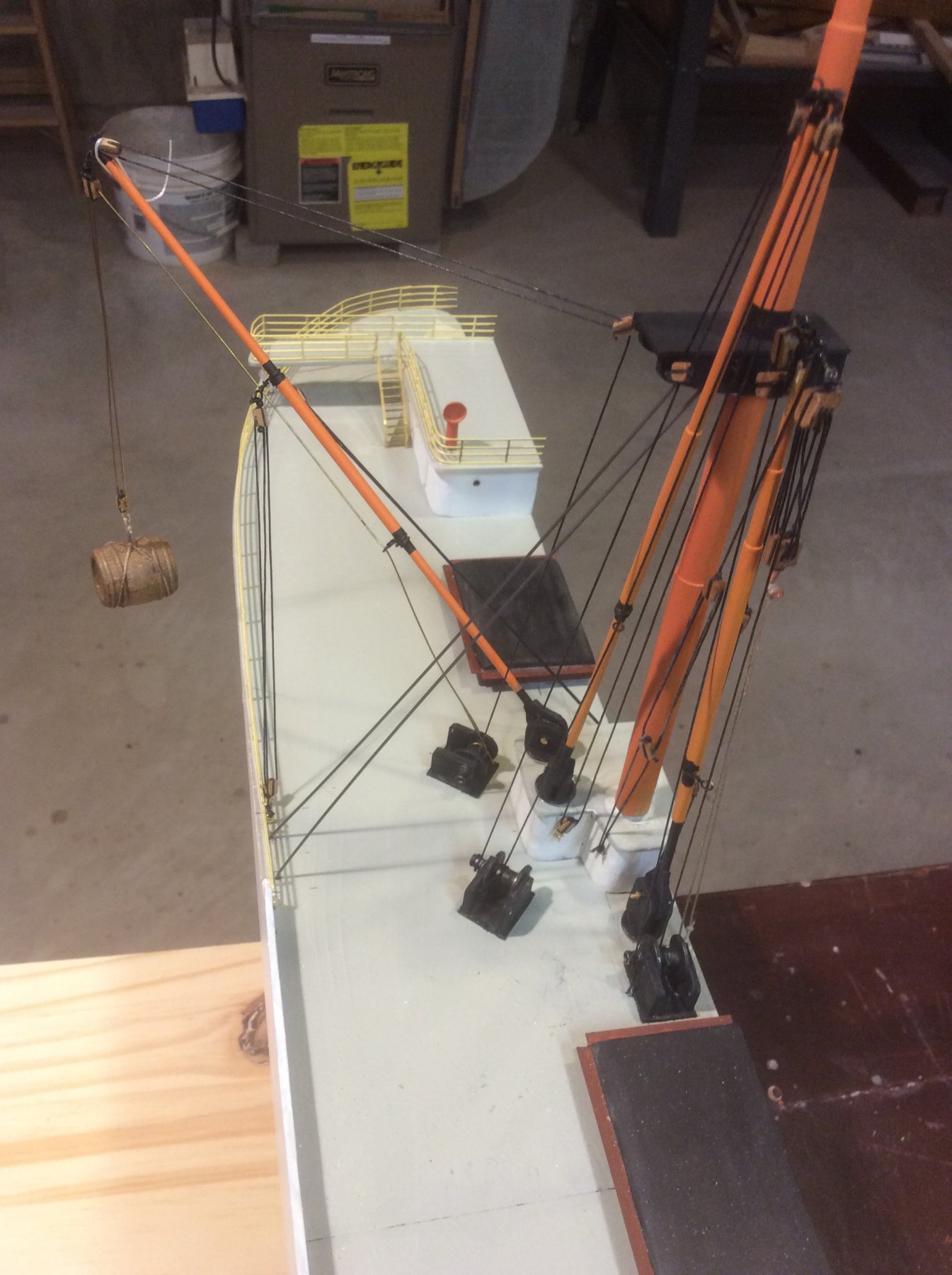
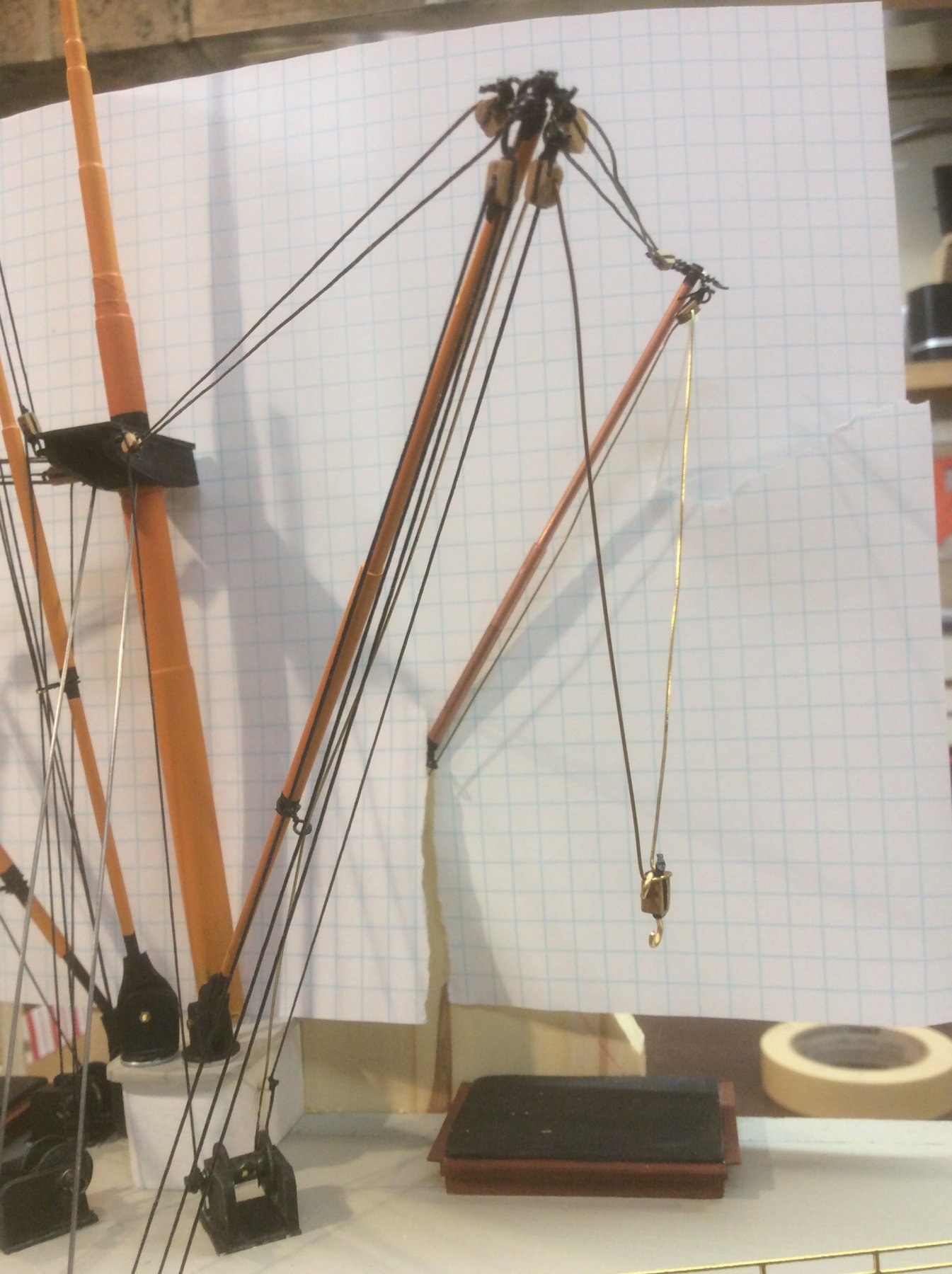
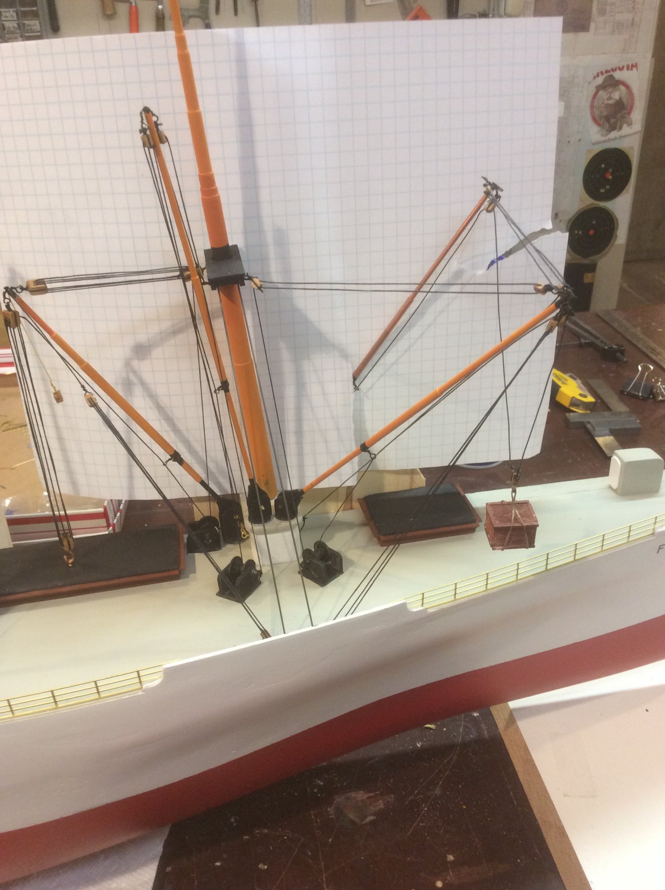
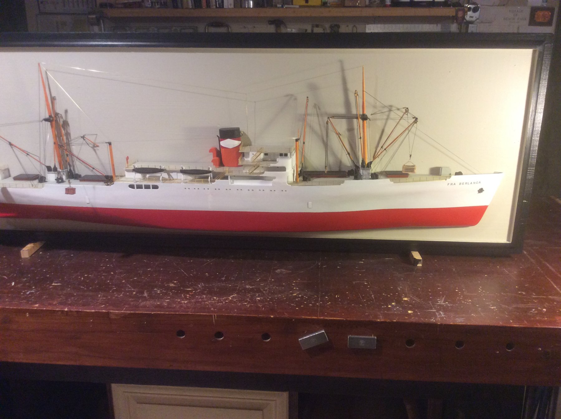
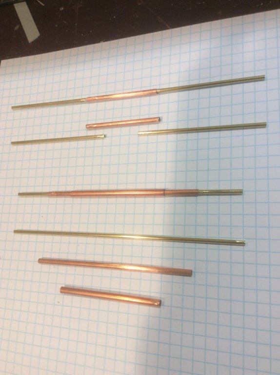
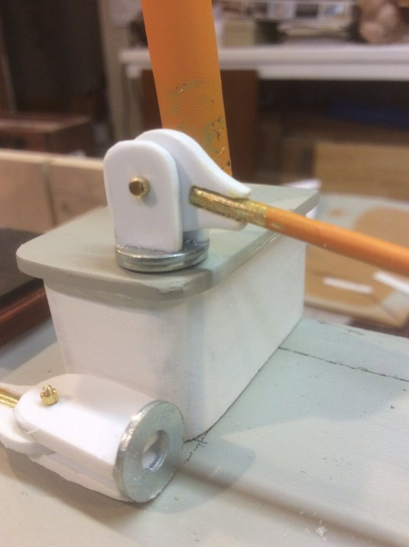
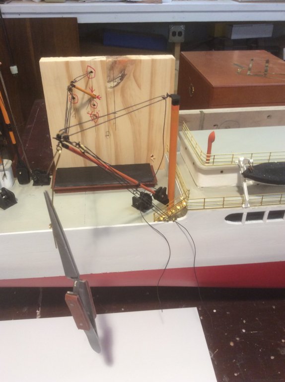
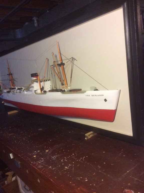
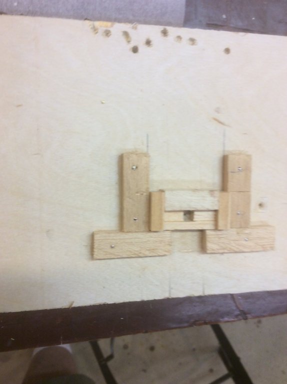
Fra Berlanga cargo handling booms were arranged with four booms occurring on each of two boom tables elevated above the deck, fore and aft, and two “jumbo” heavy booms, each located near one of the boom tables, on the deck, to serve the larger fore and aft hatches. I fabricated the booms of telescoping brass and copper tubing. The gooseneck that hinges the boom at its base was made of polystyrene and a fine brass nut and bolt, and steel washers at the base. It does look like a goose, with a big cigar! Winches were modeled with polystyrene, brass tubing and steel flat washers. These elements were of sufficient detail to illustrate the basic working of the rigging. I wanted my Fra Berlanga to represent a ship handling cargo at dockside, with booms active in several configurations. Some booms are in a stowed position; a single lightweight boom is active at the aftermost hatch; two booms are active at the after kingposts; at the forward main hatch the jumbo boom is active; and at the foreword most hatch, two light booms are active. Modeling the single after hatch boom was pretty straightforward, but it did present the problem of what to do with the port side guy, which should terminate anywhere between ship centerline and near the port side rail, which in my half-model doesn’t exist. I decided to include this guy, but just have it terminate at the deck at the ship centerline. At the after main hatch, I have the activity of the two booms from the port and starboard kingposts. I wanted to include the portside boom, since it extends to the starboard side of the centerline, so I included the upper portion of this boom, and just allowed the lower portion to “disappear “ into the background. Here, a temporary backboard is mounted hold rigging until the final backboard is added. I used a similar arrangement at the forward hatch being served by two booms mounted on the boom table. Again, the portside boom and it’s rigging elements from that side disappear into the background. The final bit of rigging was the stays and radio antenna. Finally, Fra Berlanga was ready for mounting onto a backboard. Finished backboard, with appropriate rigging disappearing into it. Fra Berlanga was a good project. I learned a lot about cargo ships, United Fruit Company, “Banana Republics” and some modeling techniques, while being able to provide a friend with a piece of family history. Overall, very rewarding hobby. Thanks for following, and for kind comments.


- 14 replies
-
- 4
-
-
- fra berlanga
- banana boat
- (and 2 more)
-
Please accept a comment from an absolute novice: I have often thought that the “16th century planking rule” you mention must have applied (except, perhaps, on the day they were launched) to nearly all wooden ships, especially warships, that went on multi-year voyages, far from home ports. I find it hard to believe that after several years at sea, battling foul weather and reefs, not to mention cannonballs, and the lack of good timber remote from home or friendly ports, that given such conditions, planking rules other than the one you mention were the norm. Of course, all evidence of my theory probably rests at the bottom of the sea. Absolutely enjoy your wonderful build.
- 756 replies
-
- 3
-
-
- galleon
- golden hind
- (and 2 more)
-
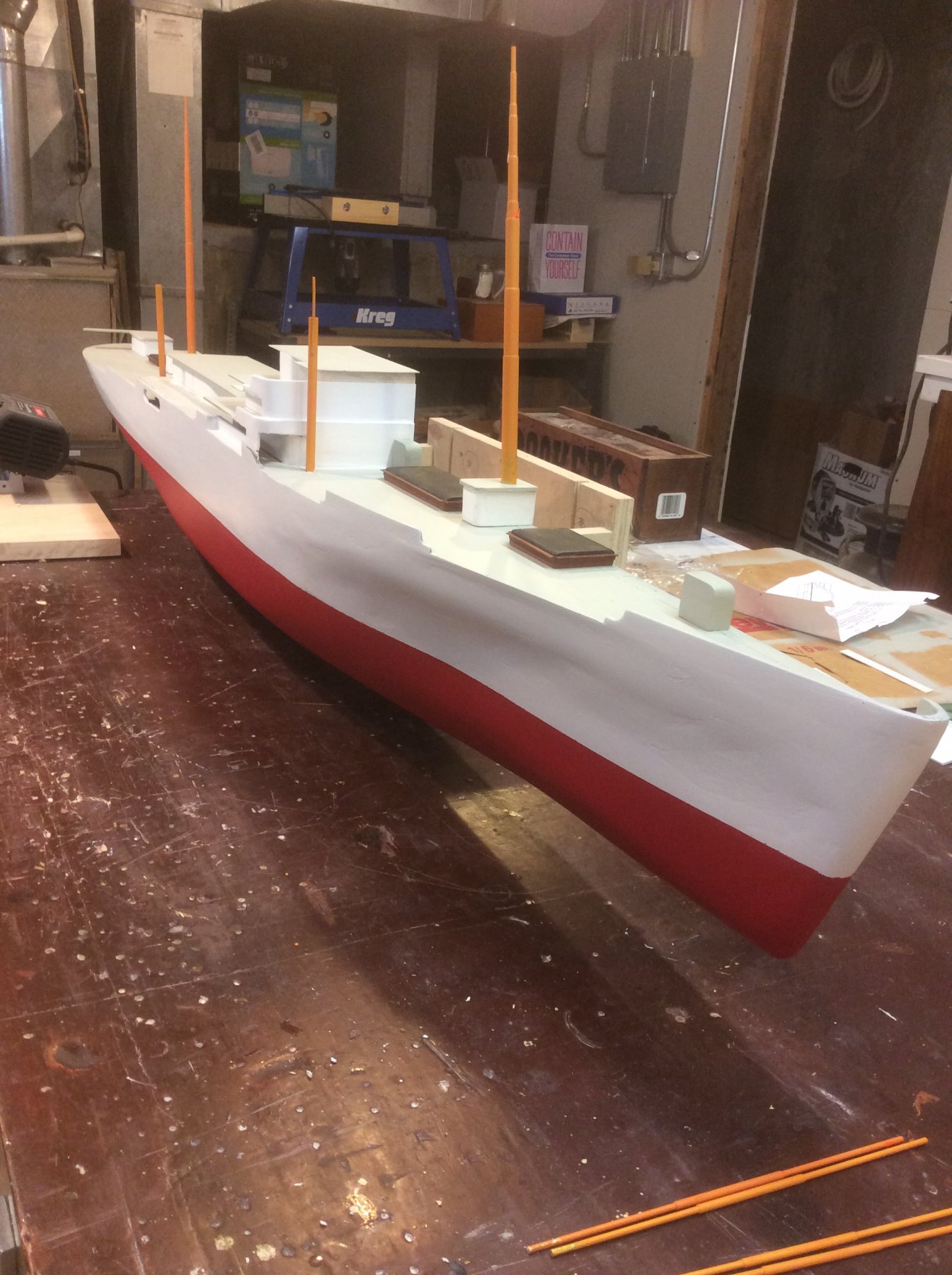
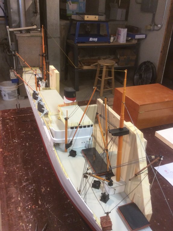
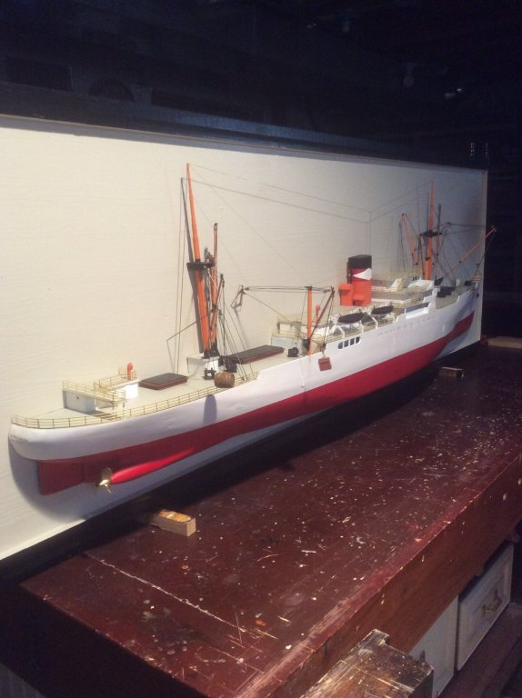
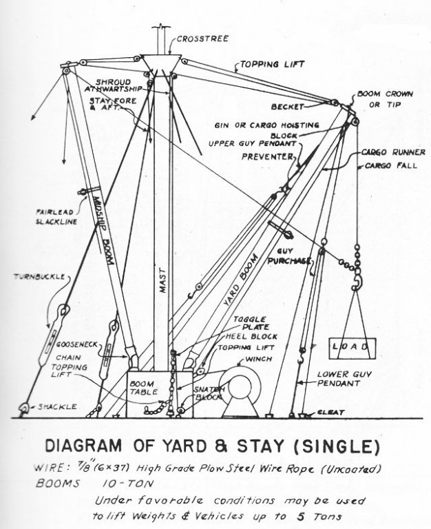
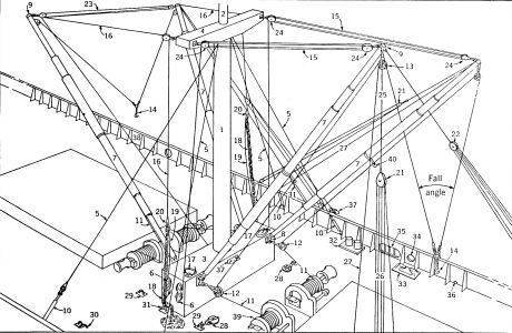
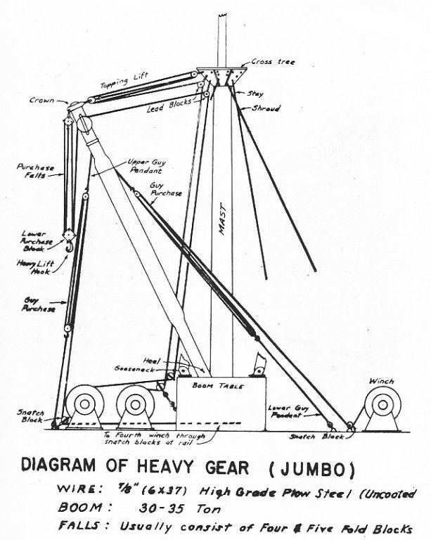
The masts and kingposts were only temporarily fitted in the previous pic, and were removed for addition of additional deck details. I used brass accommodation ladders and rails from Blue Jacket. Here I departed from what Fra would have actually looked like, by leaving them natural brass ... I’m sure a working ship would never have these, no matter how much of a “spit-and-polish” Captain she may have. A concession to artistic license. Funnels, ventilation goosenecks, lifeboat stanchions and boats, portholes, and her name, were also added. Oh, yeah .. the propeller shaft nacelle was extended, and the propeller added just prior to detailing the decks. Not being familiar with the rigging of mid-20th Century cargo ship, and wanting my Fra model to represent the characteristic cargo handling equipment, I began an internet search for information. Several diagrams were instructive. Several lessons were immediately evident. First ... there is a lot more rigging than I ever thought. Second... one, two or even four booms might be attached to a single “hook” to handle cargo out of a single hatch. Third ... Fra was equipped with a “Jumbo” boom at each mast. [Images from HyperWar Foundation, ibibilio.org] Depicting these schemes on a half-hull model will present some unique modeling challenges.

- 14 replies
-
- 5
-
-
- fra berlanga
- banana boat
- (and 2 more)
-
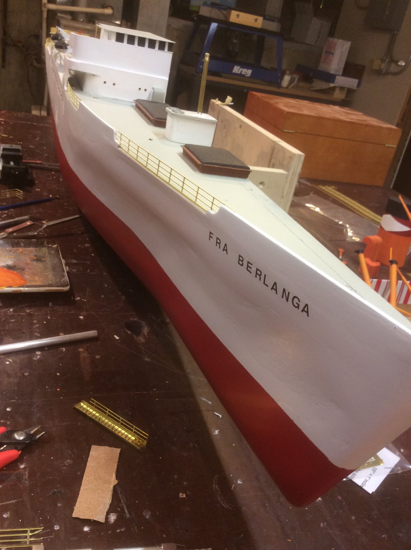
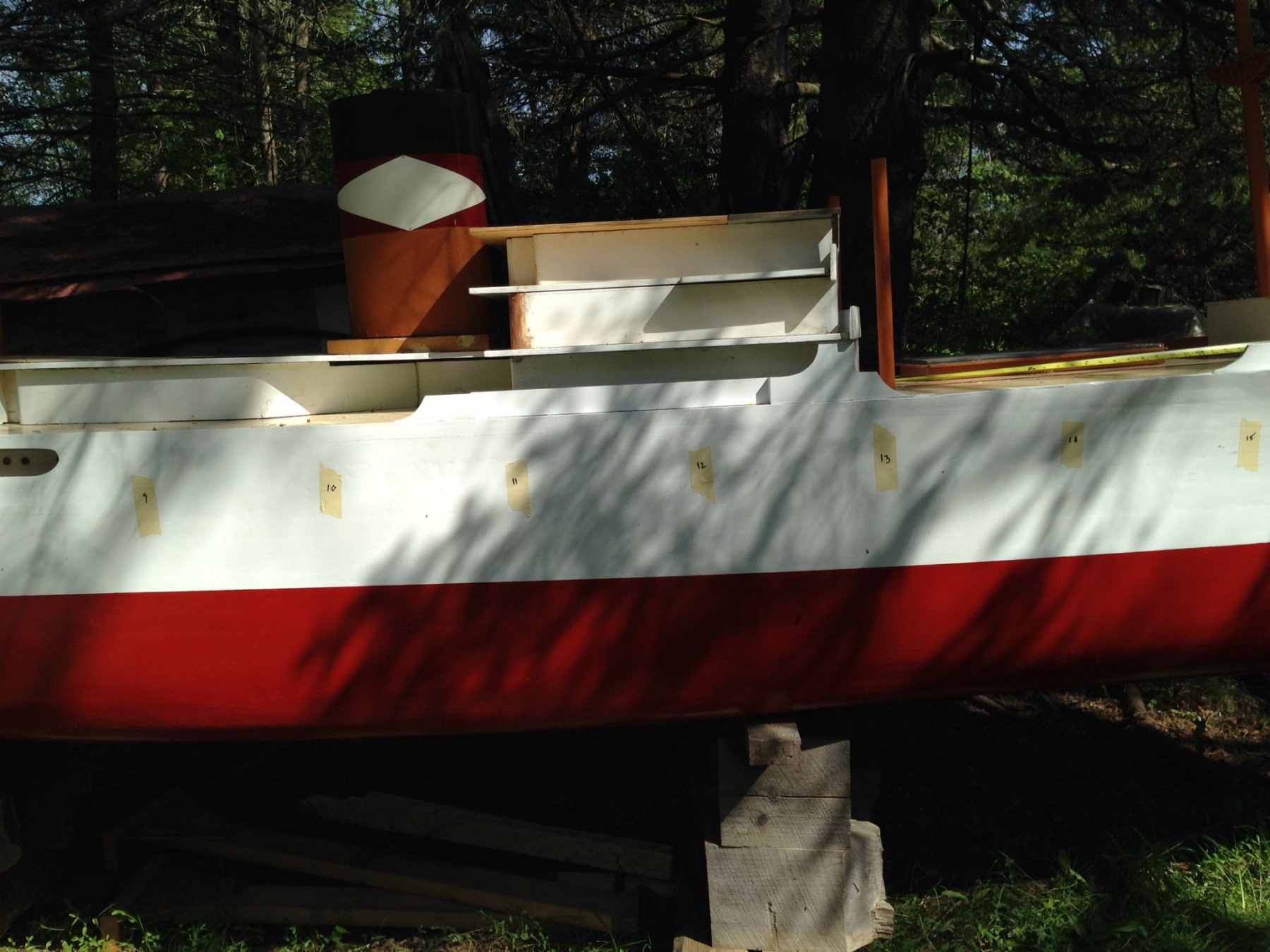
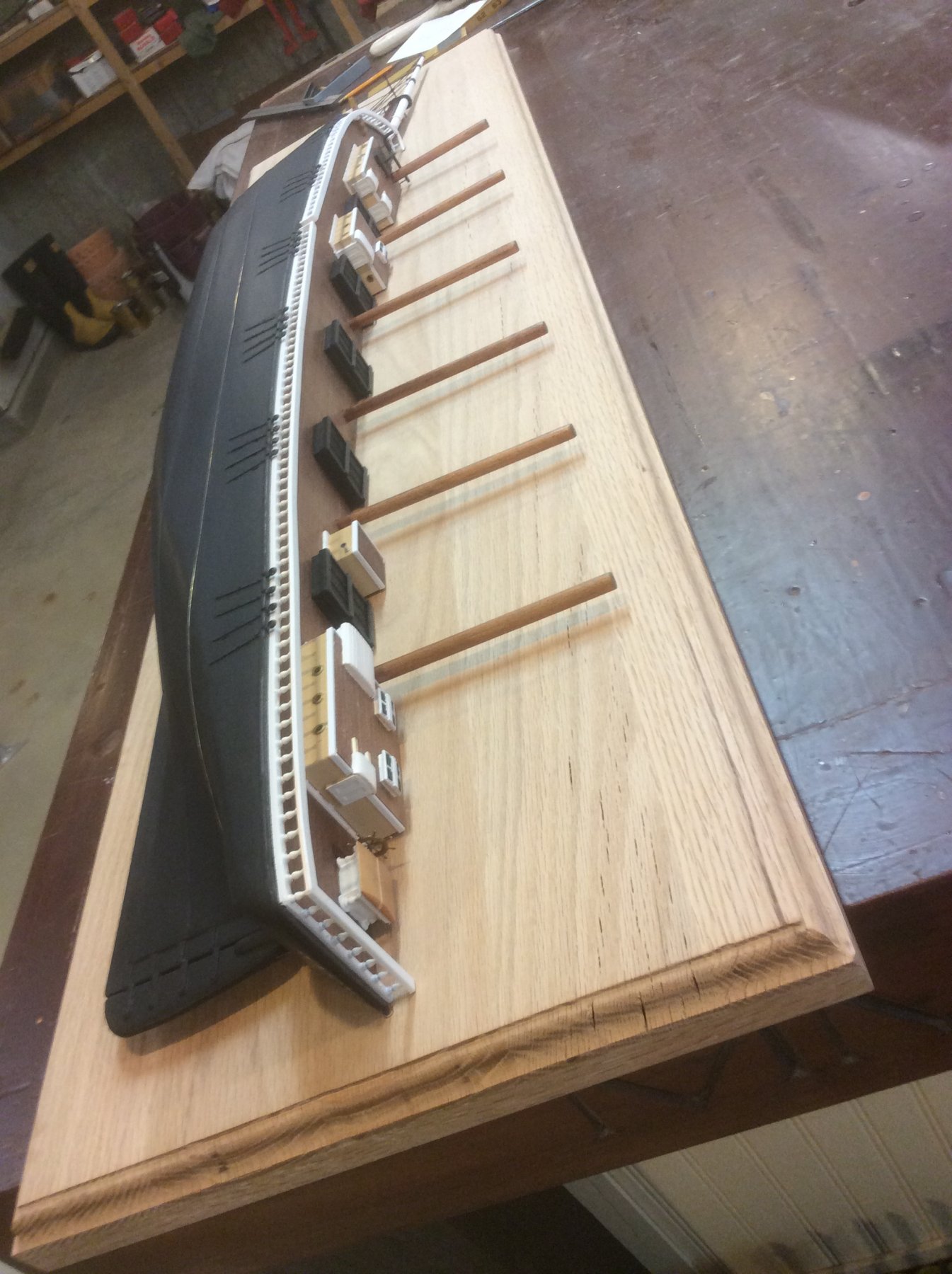
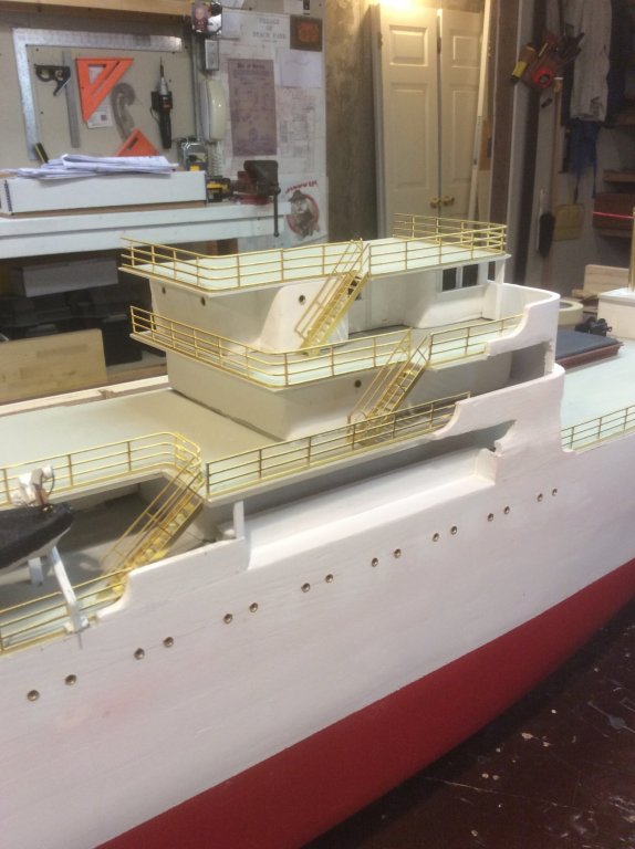
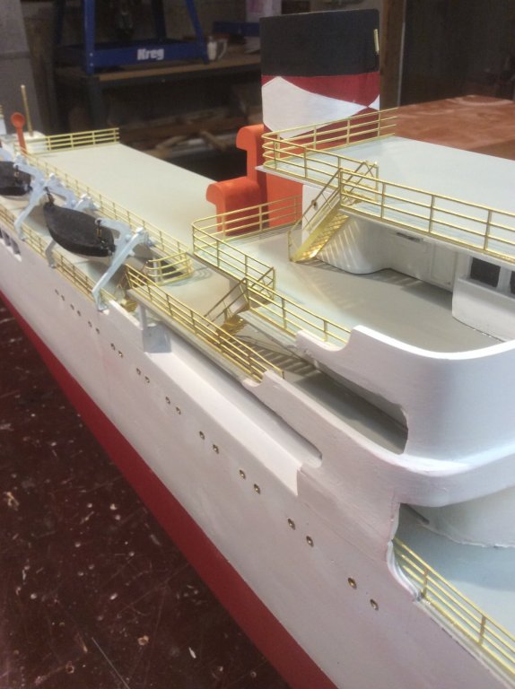
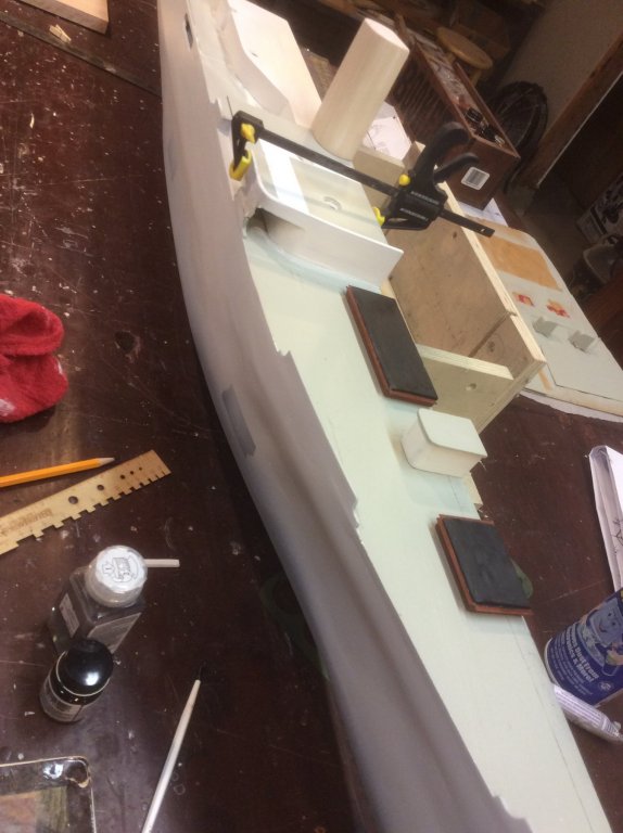
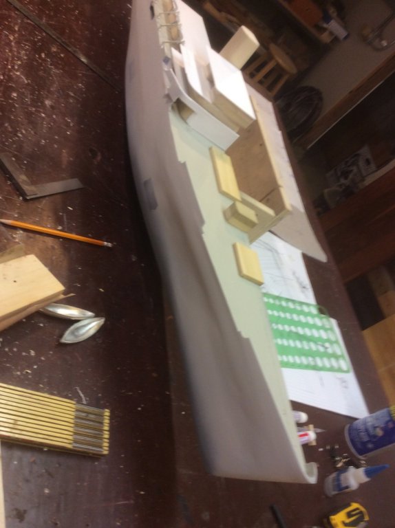
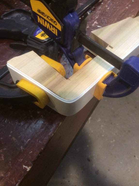
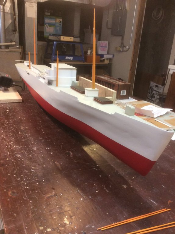
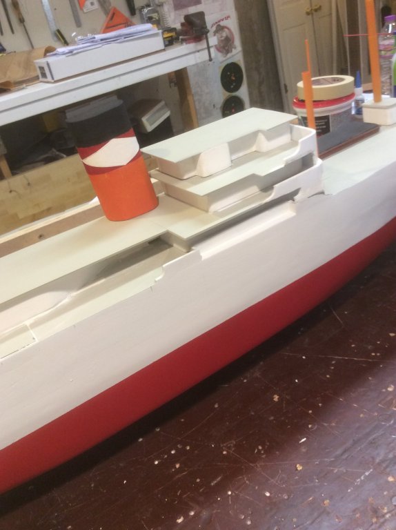
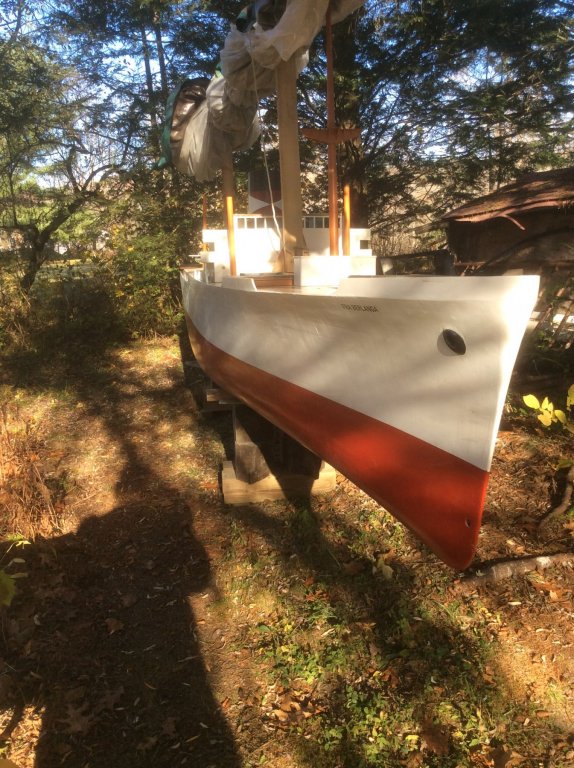
The deck structures are rather simple. There is a catwalk and machine house for rudder control equipment, then the rear after cargo hatch, the raised hoist table, the fore after cargo hatch, then the midship section with four superstructure decks. Forward of the midship superstructure is the main forward cargo hatch, the forward hoist table, and the smaller fore hatch. The several decks of the superstructure are made of thin sheet polystyrene. To fabricate the curved front of the superstructure, I created a curved form and laminated together three pieces of 1mm thick polystyrene. In my initial attempts, I used CA to glue together the pieces. To my surprise, the styrene was weakened by the CA, and the pieces soon snapped while clamping. I then repeated the process using modeling cement made for styrene. Then used CA to fasten the molded polystyrene pieces to the wooden superstructure pieces. After completing the deck structures, the foremast, mizzenmast and fore- and aft kingposts were added. These were fabricated of copper and brass tubing. Fra’s red and white hull colors were added, as well as United Fruit’s characteristic stack colors.

- 14 replies
-
- 5
-
-
- fra berlanga
- banana boat
- (and 2 more)
-
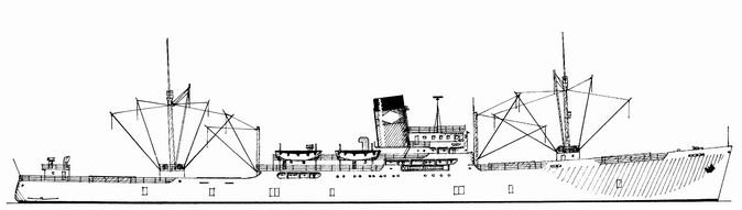
I thought I would add a couple comments about scale and level of detail of my project. Scale I listed the scale of my model as 1:96, or 1/8”=1’-0”. The truth is, I don’t know what the scale really is. The resources I was able to consult while developing the plans varied in the length listed, as I mentioned earlier. The issue was further confused by data given about Fra Berlanga’s many sister ships. Also, I could never really reconcile the length of the test tank model (about 20’-4”) with any of the referenced ship lengths. The test tank model appears to be have been built closest to a scale of 1:24 ( or, 1/2”=1’-0”) but that results in a hull length of about 490 feet, which far exceeds any referenced length. Since my field measurements of the test tank model are the basis of the lines of my model ( mine being really a model-of-a-model-of-a-ship), and since I built to 25% of the field measurements, I can only say that my Fra is about 1:96. In the end, that’s probably good enough. Level of Detail I never imagined detailing this model to the same level as I have done on ships of sail (think: belaying pins, deadeyes), but wanted enough detail to evoke an image of the function and character of the ship. I thought the image below, enhanced with representative colors, was a good guide. It is included in a US Maritime Commission listing of cargo ship types. (Drawing by Karsten-Kunibert Krueger-Kopiske). It gives a good representation of the general arrangement of the cargo handling rig, location of superstructure, and suggestion of hull shape and proportions. Lastly, while I am calling this a scratch built model, I am clearly using some manufactured components (propeller, anchor, lifeboat stanchions, rails and ladders and a few other items from Blue Jacket) which takes me out of the rarified level of EdT’s Young America and Sr Amilio’s Montanes as well as many other purists (the work of whom I am in awe of), I am equally as clearly not building a kit. Nonetheless, this project has presented its own lessons and opportunities to learn the craft. Enough talk ... on to modeling.
- 14 replies
-
- 4
-
-
- fra berlanga
- banana boat
- (and 2 more)
-
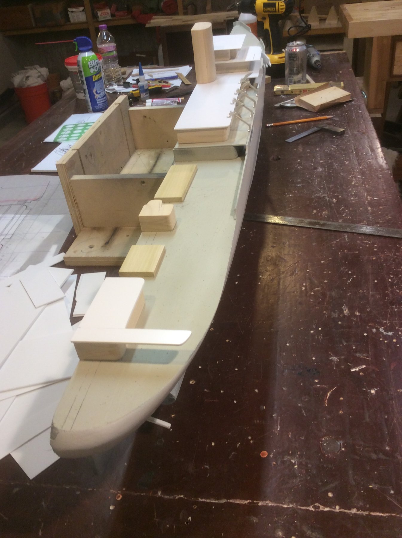
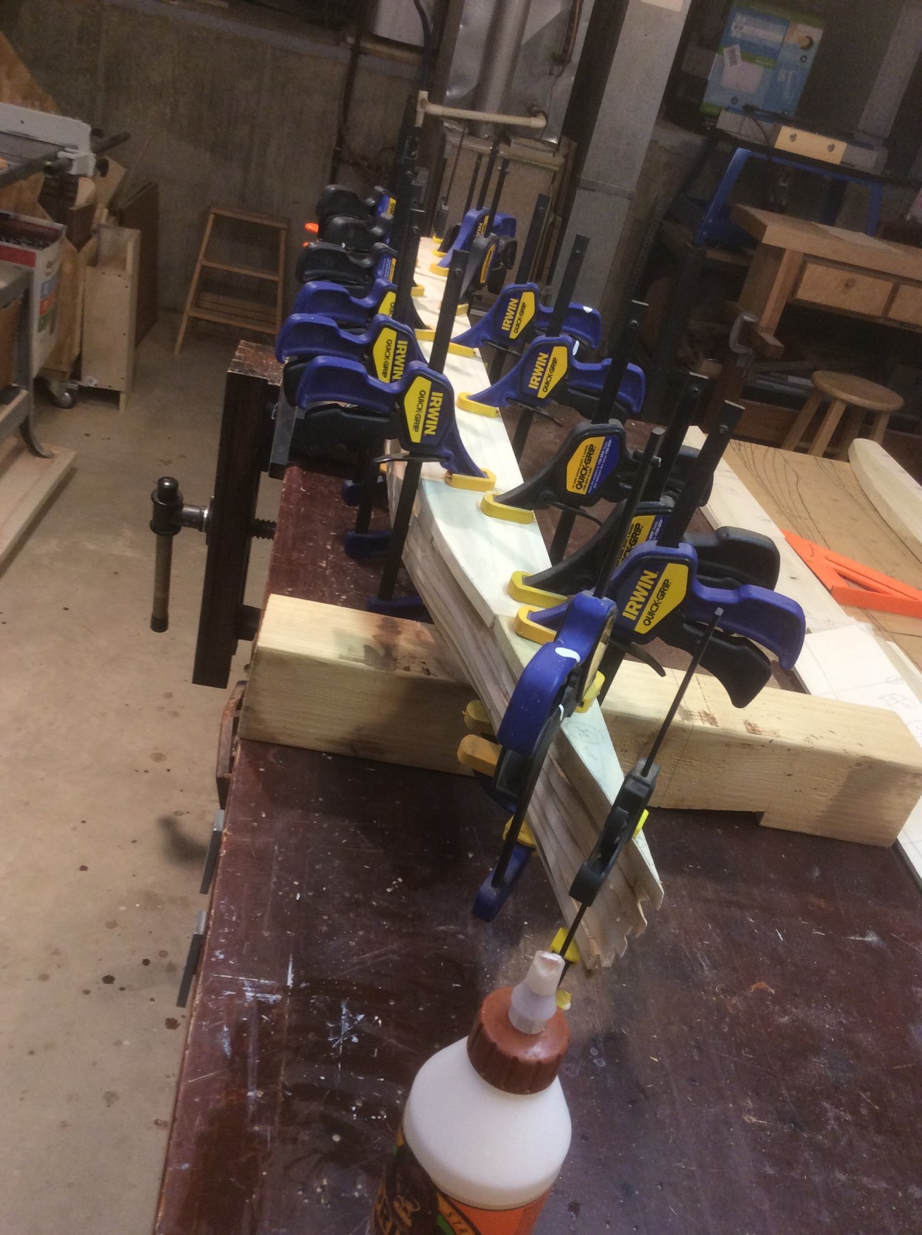
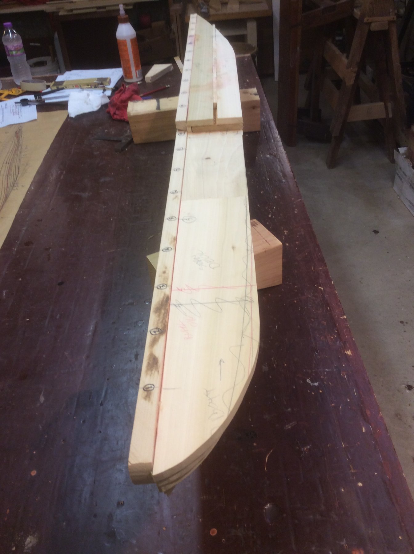
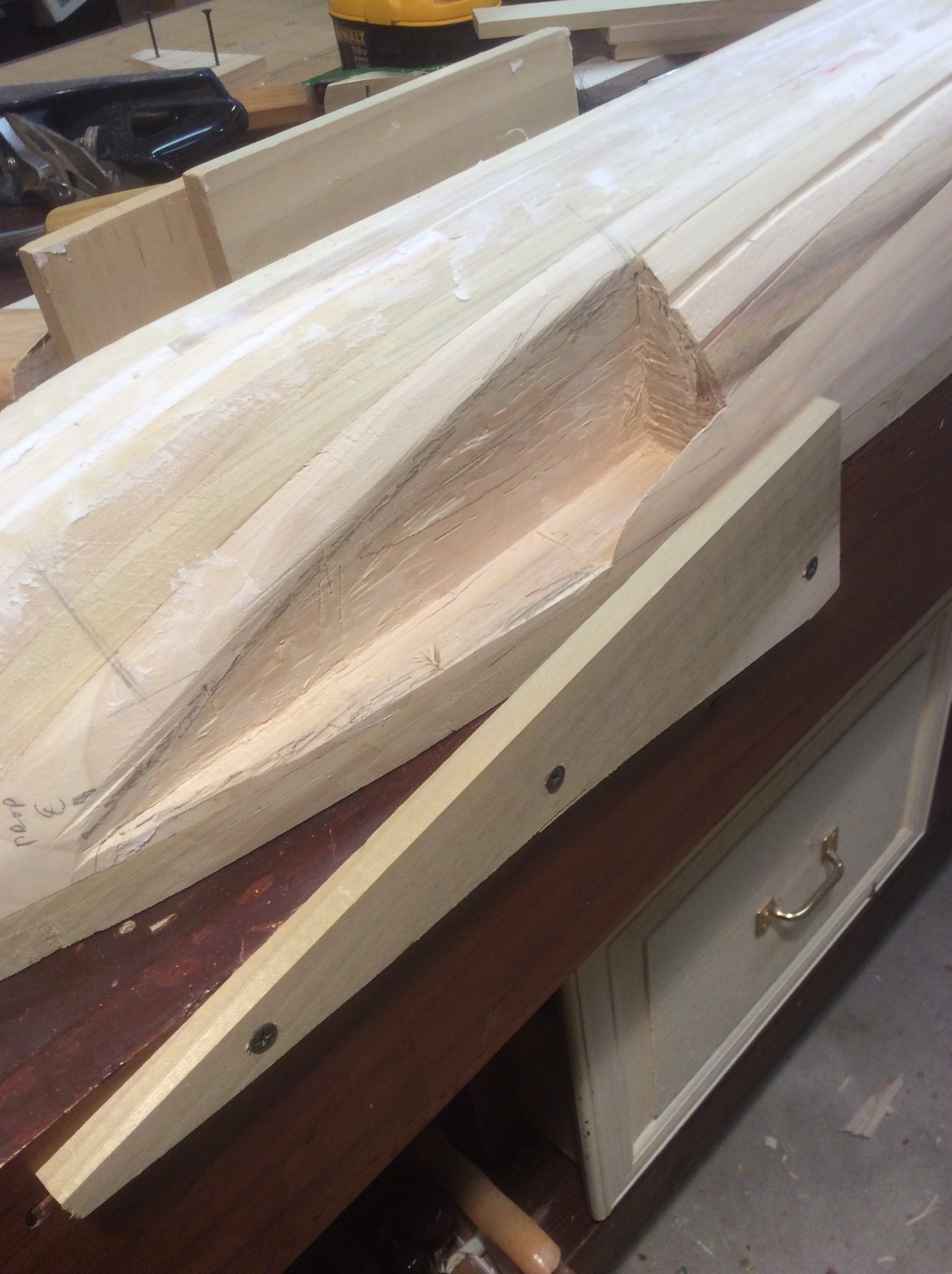
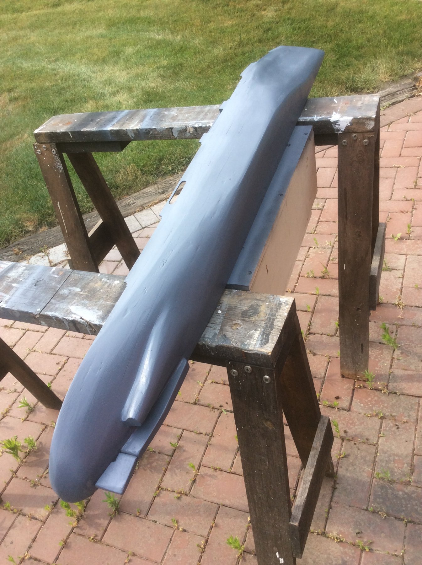
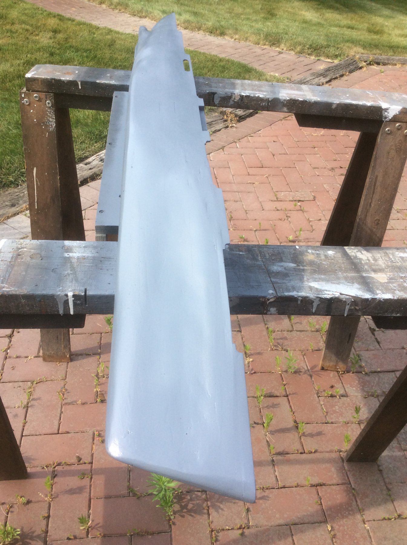
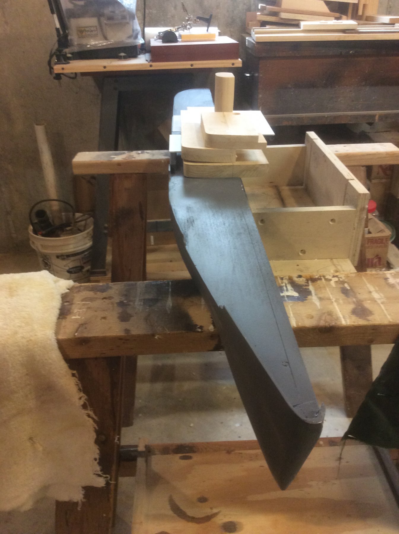
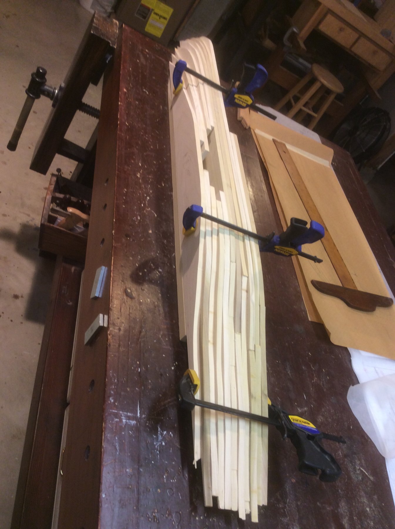
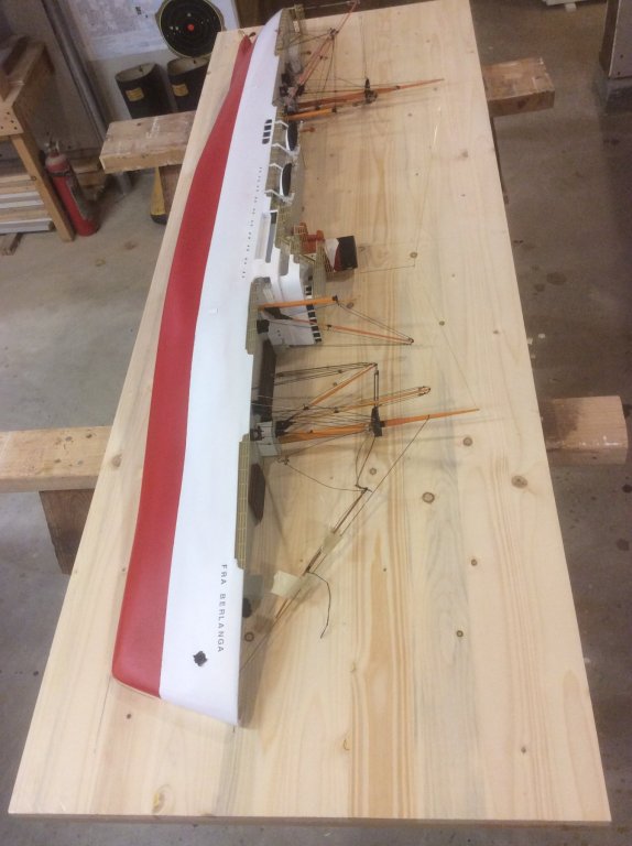
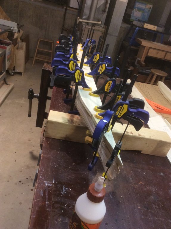
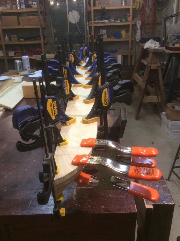
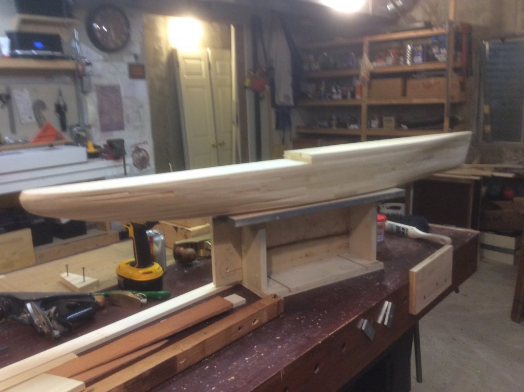
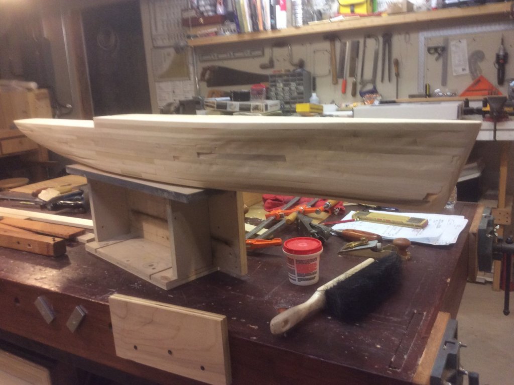
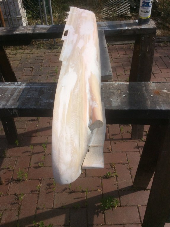
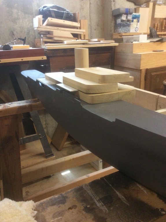
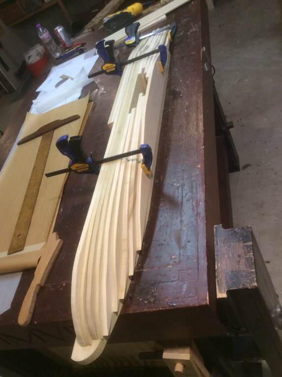
Assembling the “sandwich” by glueing together each cutout was next. You can never have too many clamps. The width of each of the layers of the sandwich is ( obviously) from the ship centerline to the outboard curve of the hull. Because a half-hull generally stops at the centerline, this creates a problem for modeling masts, or other features that are located on the centerline. Either those features must be cut in half (difficult with masts), mounted off-center, or the hull model must be more than a half-hull. I chose the last option by adding a “spine” at the port side of the centerline. This 3/4” thick spine makes my model a “half-hull-plus-six-foot” model. Not only does this allow mounting fill diameter masts, but adds adds another dimension ( pun intended) to the visual impression of the bow shape (more on that later). Attacking the sandwich with bench planes, spokeshave, rasp, chisels, gouges and sand paper, the near final hull emerged. I chiseled out a portion of the hull to insert a separate carving of the propeller shaft nacelle, and also added the keel and rudder, topside bulwarks and the first application of wood filler. Applied the first coat of primer, which highlighted the many defects. After a sequence of further sanding-filling-sanding-filling-priming-sanding-filling-priming, (sometimes I think my models are equal parts of wood, filler, and paint) she was deemed good enough to return to the shipyard for fitting of the rudiments of a superstructure. Here the extra six feet width created by the “spine” adds depth to the bow.


- 14 replies
-
- 8
-
-
- fra berlanga
- banana boat
- (and 2 more)
-
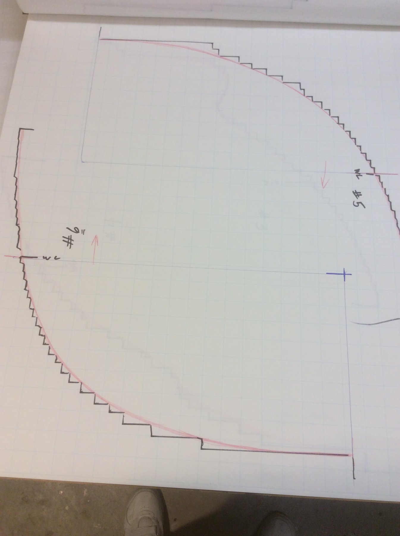
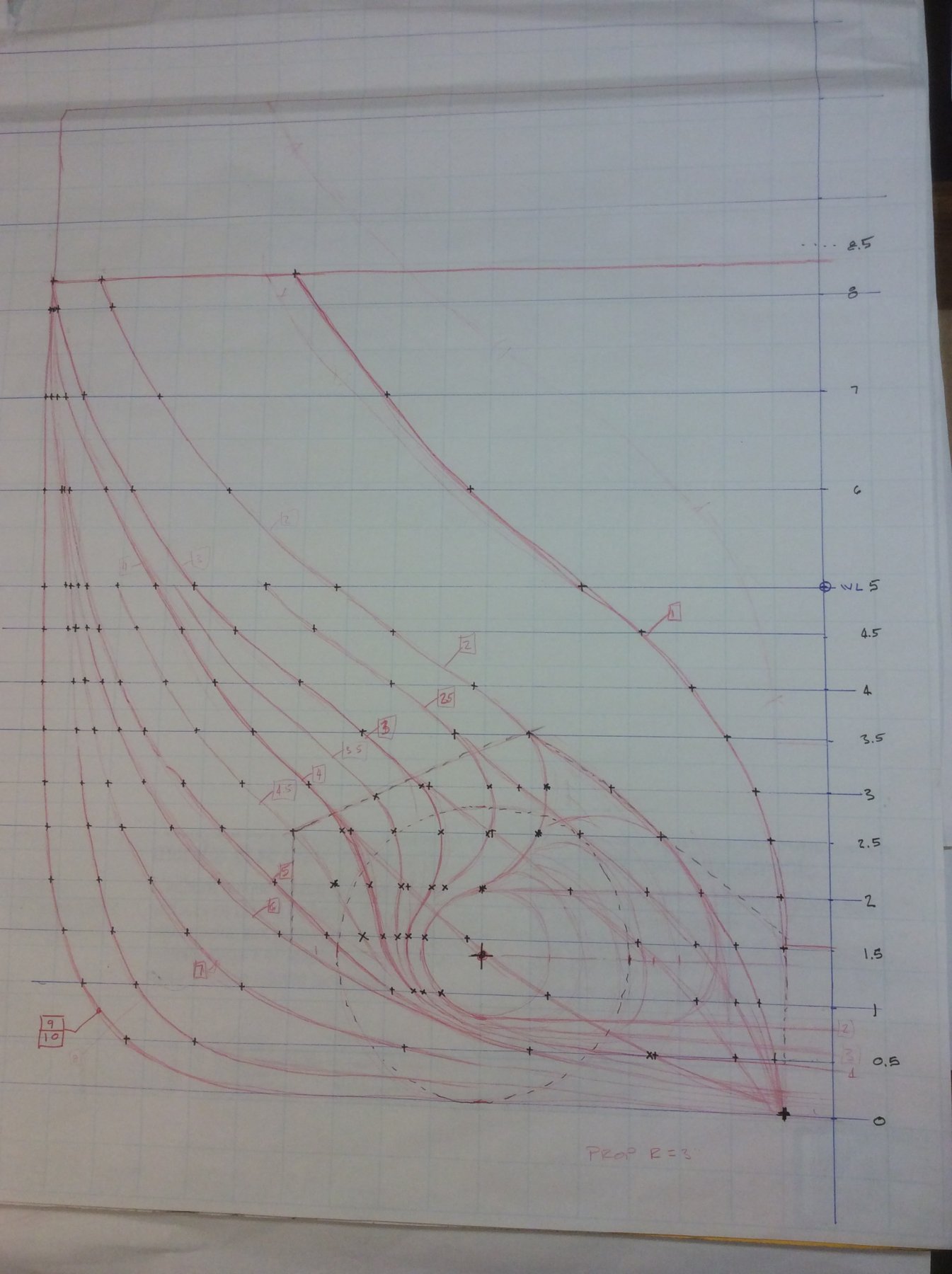
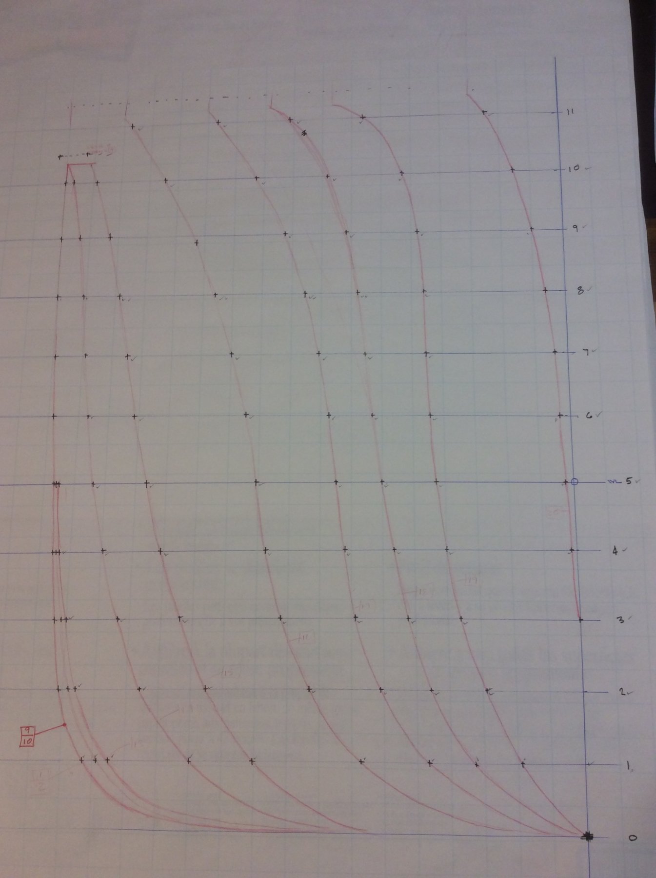
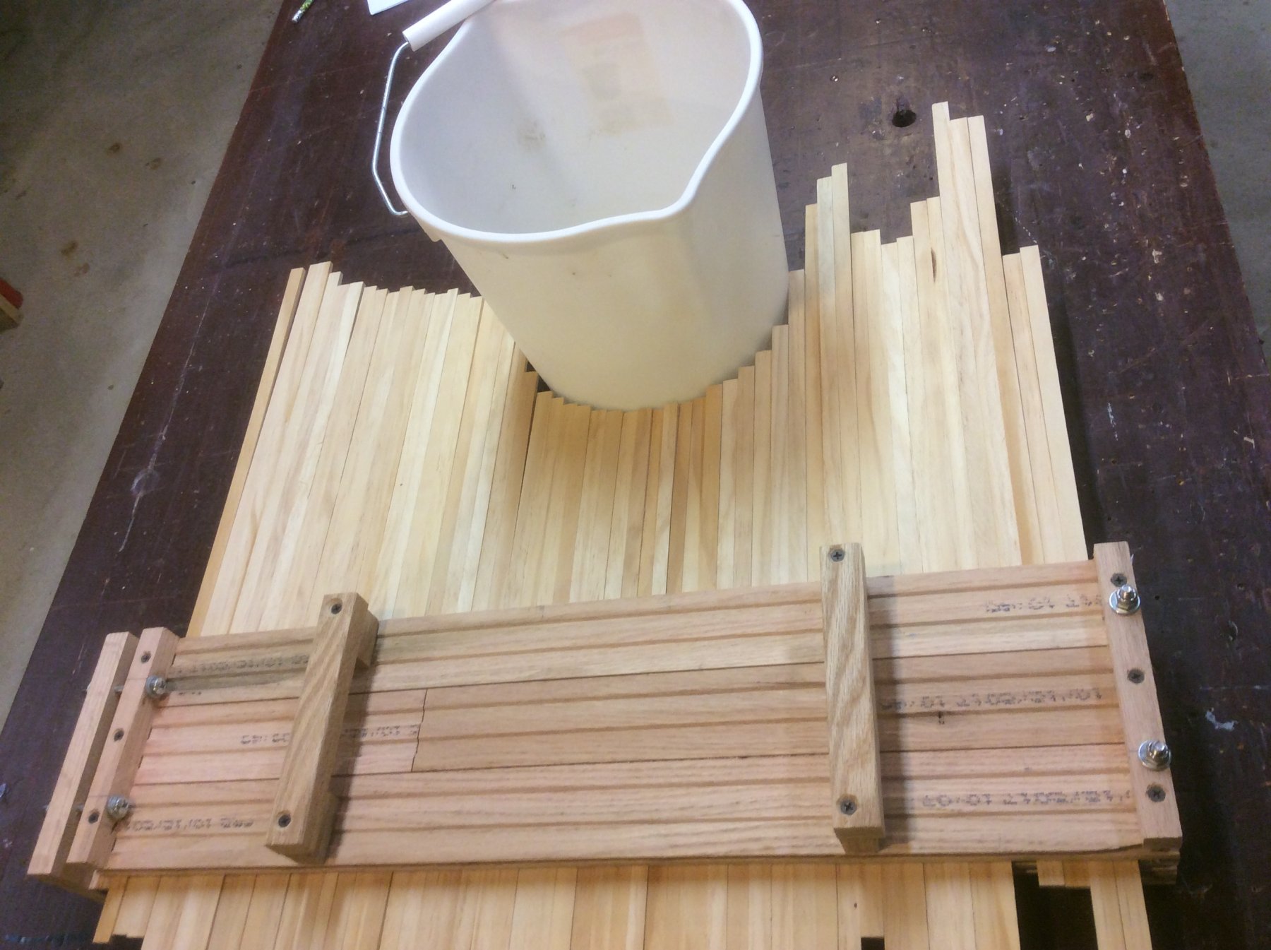
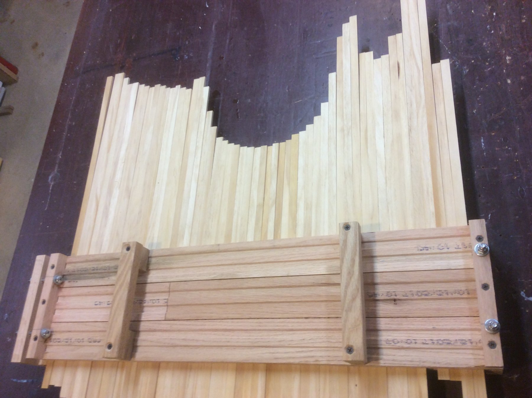
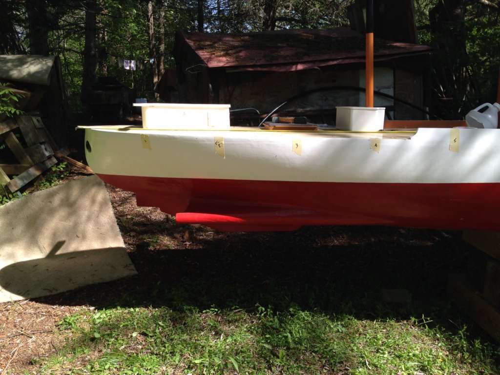
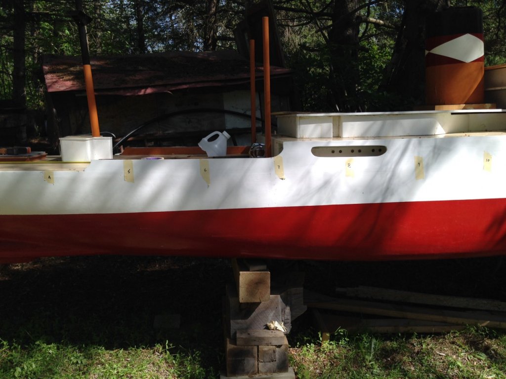
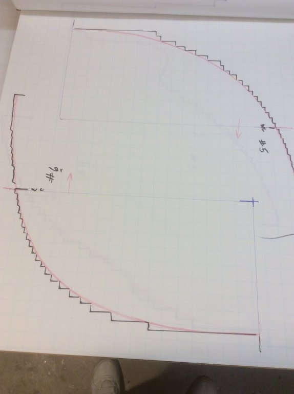
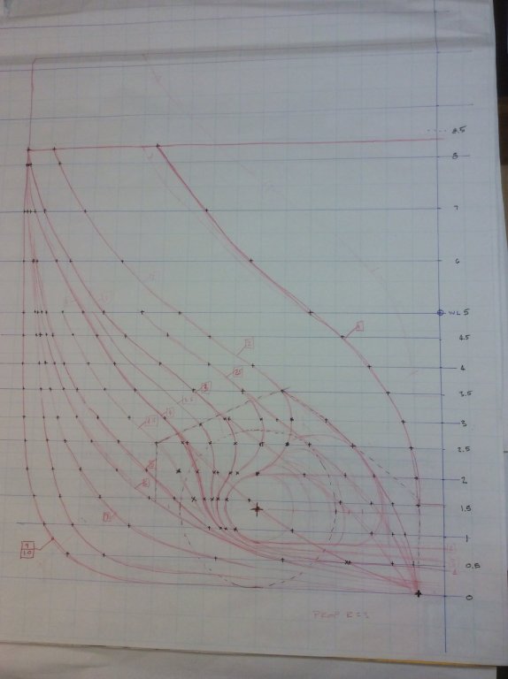
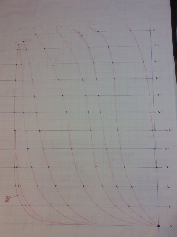
Having decided on how to make the hull measurements and creating the tool to do so, I descend on Mr Morris’s 20ft model, and collected the profiles. First step was to mark out the section intervals on the hull, 12” apart, with masking tape. In the second pic above, notice the milk jug on the deck ... used for bailing the model when afloat. Gives a good idea of the size of this model. I dont have any pics pics of the contour gauge in action, since using it was a two man activity: one person to hold the gauge plumb in place against the hull, the other to adjust the gauge “pins” to the contour. But, once a contour was taken at a section location, the outline was traced onto large graph paper. The two outlines of the gauge measurements, Section #5 and #6, are shown above. The location of the waterline and ship centerline were also recorded for each section. The intersection of these two lines established a common reference for all 20 sections, and was used to align them all. The “sawtooth” outline from the contour gauge measurements were smoothed into a curve (red line) representing the hull. The curves for each section were then traced onto a single section drawing for the aft sections, and another for the forward sections. After establishing lines parallel to the waterline, offsets from the ship centerline to the hull line could be measured for each waterline and, after applying a scaling factor ( more on that later), each point is plotted onto a plan view, thus creating a series of waterline curves. Tracing each parallel “ waterline” onto a 1/2” thick poplar board, cutting out each layer of the sandwich, then stacking the boards in order, resulted in something vaguely resembling a half-hull ship model. The elapse time for the research, field measuring, drafting and first appearance of something tangible was just over one year.


- 14 replies
-
- 5
-
-
- fra berlanga
- banana boat
- (and 2 more)
-
You might find when you rig your ship that minor warping of spars can be mitigated by the tension on the lines.
-
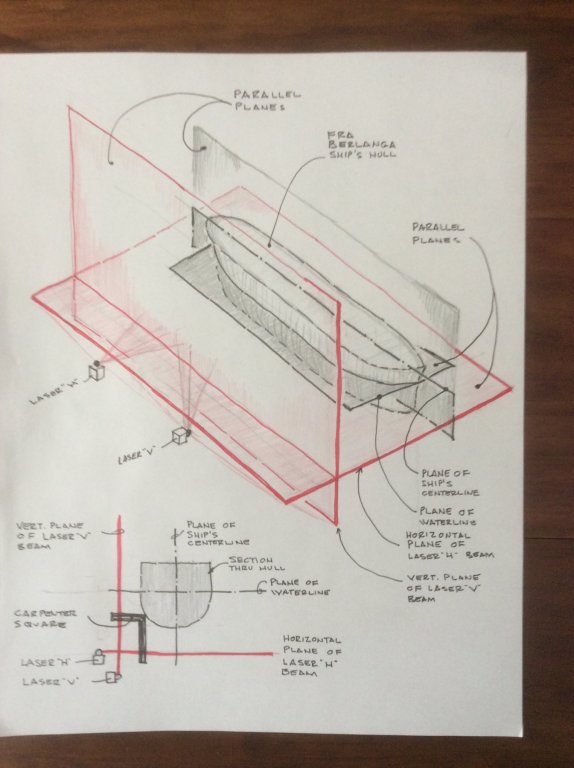
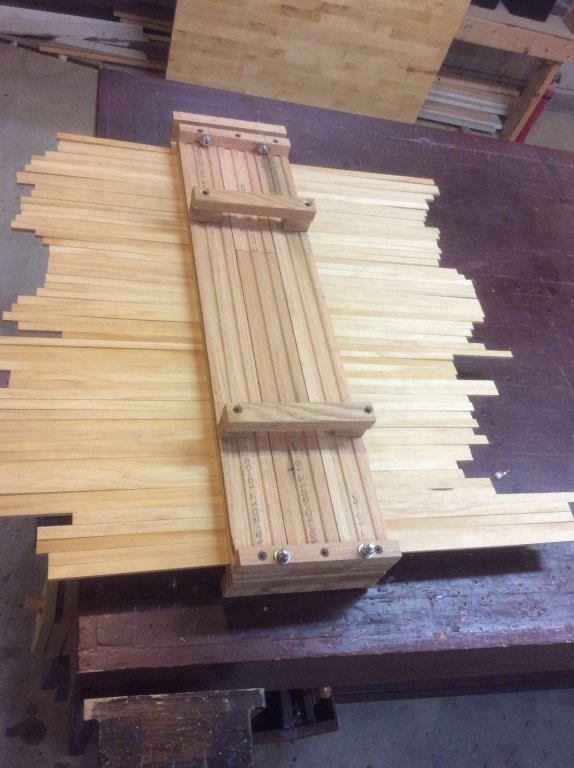
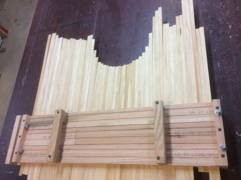
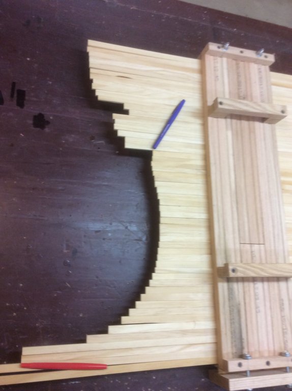
Valeriy V: Laser scanning is what originally came to my mind, as well. However, cost was of primary concern, cost that would be exacerbated by the fact that Mr Morris’s 20ft long test tank model was located in a semi-rural location in Maine. I did consider a laser based methodology of my own, which I described in a post under another topic: I would set up two laser levels, one with a horizontal beam parallel to the ship’s waterline, the other parallel to the ship’s centerline. The horizontal laser beam would be set at an elevation just below the keel, and the vertical laser beam set just outside the port or starboard side. The model’s beam is 34”, and draft is 10”. Using a carpenter’s framing square, placing the heel of the square on the hull would allow reading offsets from the two laser beams on the blade and tongue of the square. Small levels would have to be secured to the blade and tongue of the square to assure it was plumb and level. Station lines would be taped to the hull along the waterline at recorded intervals to guide in the placement of the square. However, I discarded this approach. In theory I think it was sound, but impractical in the execution. Given the outdoor working conditions, it would have been very difficult to setup the lasers, we would be working in daylight which would make measurements hard to read, and if it were the least bit windy, the laser beams might be jiggling all over the place. How the old-timers actually took the lines off full-sized ships, would be interesting to know. I imagine some sort of scaffolding system, with registration stations from which distances to any point on the hull could be measured, then, using trigonometry, the offsets defined and plotted into a series of line drawings. Which, I think, is what laser scanning does, albeit electronically and a lot faster. But, following such a manual measuring-calculating methodology for my purposes seemed quite laborious. Then I hit on the method I ultimately used. Since what I really was trying to do was to record the contours of the ship, I created an oversized contour gauge. The frame is built of two layers of oak flooring material with about 40, 3/8”x1/8” “blades” sandwiched between. Machine screws with wingnuts allow adjustments of the compression against the blades to allow them to be positioned. Eventually, a bubble level with a zeroing quadrant was added. Pressed up against a curved shape (such as a bucket) the blades are adjusted to the shape, then clamped into place. I tested using the gauge on a canoe, and it captured the profile pretty well. the blue pen marks the gunnel, the red marks the keel. By using this device, I decided I could take contours at regular intervals along the hull, and then draw a set of sections.

- 14 replies
-
- 3
-
-
- fra berlanga
- banana boat
- (and 2 more)
-
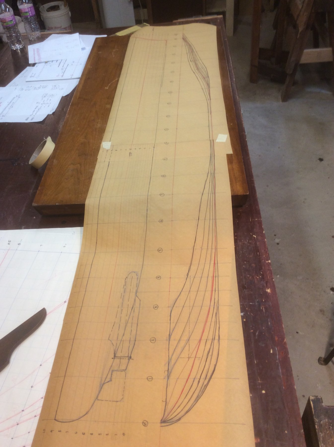
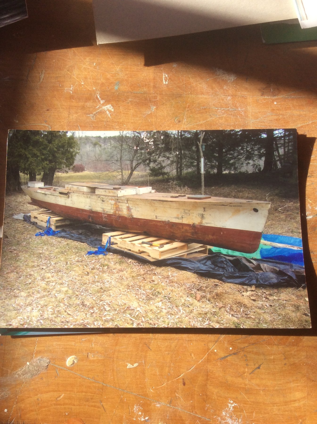
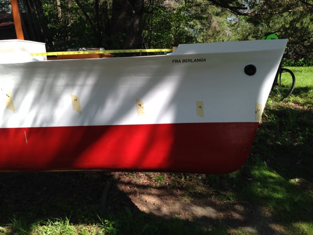
I soon learned that the most difficult part of skratch building a model of a ship that is, while not obscure, is nonetheless not popular enough to have attracted a lot of attention; that the biggest difficulty, especially for a novice modeler, is finding accurate information about the ship. The modern source of all knowledge, Google, turned up various links, most of which lead to widely varying “information”. Fra Berlanga was 431 ft long, or 469 ft, or something in between, with a draft of either 19 or 25 ft, or something in between, depending on the source. She was built either during or after WWII. Other links took me to articles on her owner (originally US Navy, then United Fruit Company) and to books about United Fruit’s (perhaps nefarious) activities in Central America. All of which was very interesting, but not very helpful in pulling together information for building a model. Even the images found were of so many different vessels, it was nearly impossible to make any conclusions about her. I then posted a topic on this Model Ship World forum, asking for Banana Boat information, and through a couple of respondents, connected with member Jerome Morris. Mr Morris has had an interest in Fra Berlanga for several years, and confirmed, much to my chagrin, that there simply are NOT any surviving drawings of Fra’s lines from which she could be modeled. But, he said he did have a source that might be useful to me. Several years before, he obtained a not-so-ordinary model of Fra. The model is over twenty feet long! It was originally used as a test tank model by the builder, and subsequently used as an instructional model for a maritime school in New York. I won’t relate the entire sequence of events that led to his possession of it (that story belongs to Mr Morris) but suffice it to say it is interesting, and his restoration effort continues. The pic above is the condition in which he received it. The pic below is representative of the progress of his restoration. To my great appreciation, Mr Morris allowed me unlimited access to his project ( and permission to use images of it). Now I had what I considered to be an authoritative represention of the dimensions and lines of Fra Berlanga. All I had to do was figure out how to shrink a 20’+ model down to something at 1:96 scale. I know how to build a model up from plans and sections, but how do you scale down from a 3-D object to 2-D plans and sections?

- 14 replies
-
- 8
-
-
- fra berlanga
- banana boat
- (and 2 more)
-
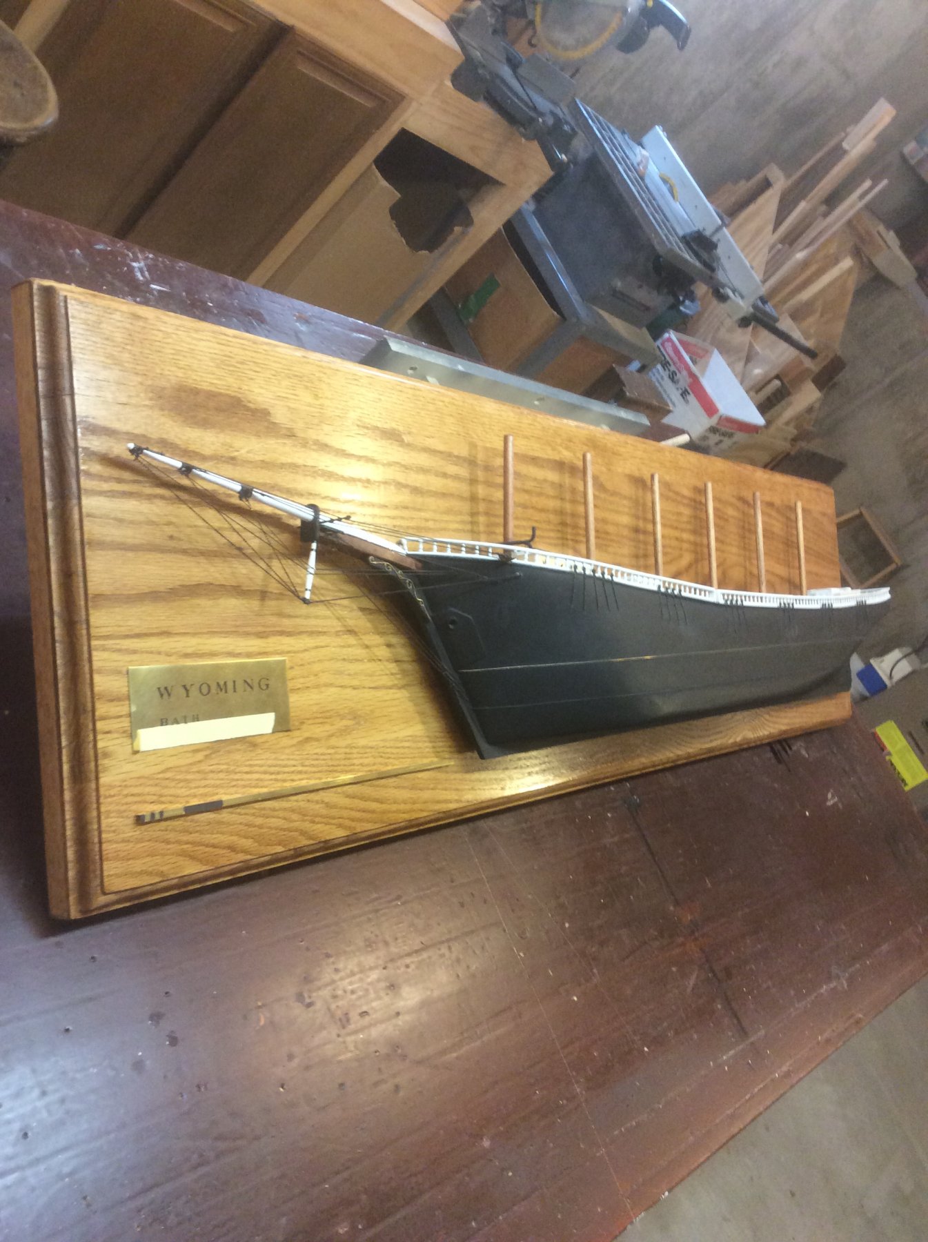
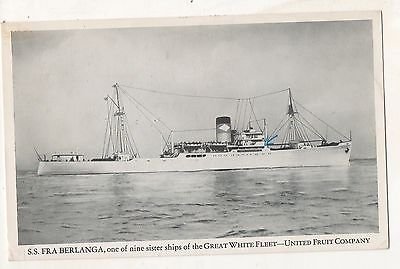
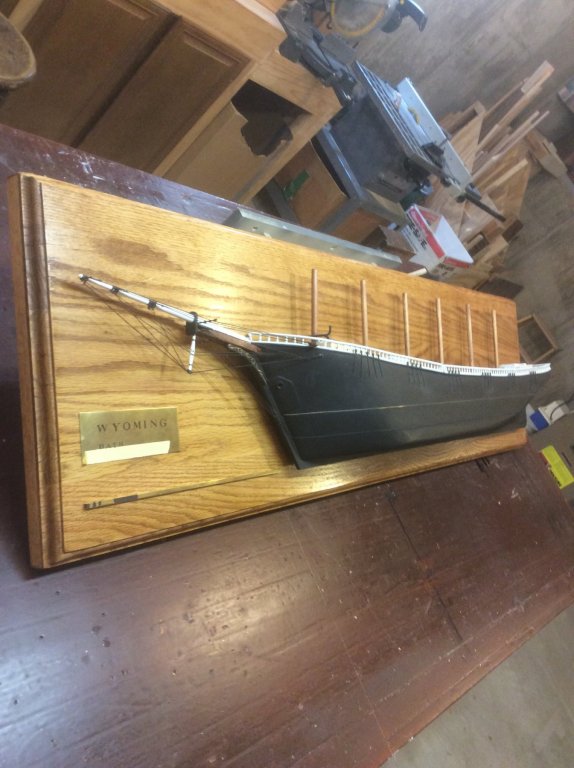
This is my first scratch build log, and it will certainly not be up in the rarefied company of many of other members scratch build logs, but still may provide some interesting information, techniques, and entertainment. This project has its genesis in a passing remark made by an in-law. Some time ago, I scratch built a half hull model of the six masted schooner Wyoming based on drawings I obtained from the Maine Maritime Museum. I did so because I wanted to get an a better appreciation of just how big she was. I was happy with the results, but, at nearly five feet long, the Admiral had objections to where she was going to hang (the model, not the Admiral). Knowing that my son’s in-laws just completed a home addition and we’re decorating with a nautical theme, I thought, “Hey, they’ll really like this!” And, so they did. During the unveiling of my “gift”, my son’s Father-in-law mentioned that his father had been a captain in the merchant marine of the Fra Berlanga. As it happened, due to many unfortunate events in family history, the only memento he possessed of his father’s, related to his ship, was a photo similar to the one attached to this log. He said he wished he had a model, similar to the Wyoming, of Fra Berlanga. That was my que ... “I’ll make you one”. Thus begins my adventure.

- 14 replies
-
- 6
-
-
- fra berlanga
- banana boat
- (and 2 more)
-
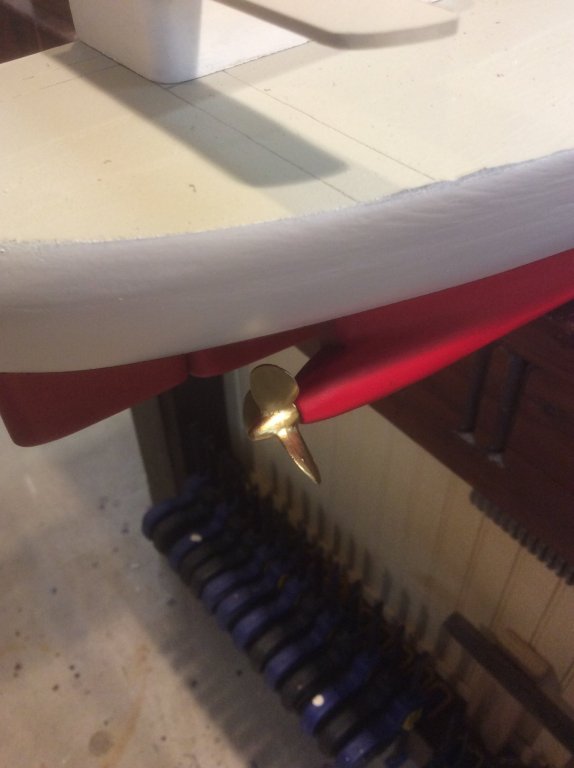
Very interested in following this build. I have built several models, now, with solid hulls, several from kits. I became frustrated enough carving down what I judged to be grossly inaccurate kit hulls that I have reverted to building up my own solid hulls, which is a lot more work, but allows me to start shaping something that more closely resembles the finished shape. Perhaps my experiences have been anomalies. I wonder if you could show in your build log how much ( or how little) you have to carve off of the hull blank to get to the finished shape. Oh yeah ... it’s nice to see you thinking about furled sails while still carving the hull ... optimism at its best!
- 356 replies
-
- 5
-
-
- red jacket
- finished
- (and 1 more)
-
Gary I used a similar methodology when building my solid hull Niagara, but created a jig for each section. Since my solid hull didn’t have any timbers extending above the deck, I had to create my own structure. I then used the same jig to form the ceiling. The details can be seen in my build log.
-
Was just catching up with your posts and saw the St Clair with the Aurora Borealis. I’ve seen them, and your painting really captures the ethereal nature of the colorful curtains in the sky.
-
Darrell Great work on the boat. Will the addition of thwarts and stern seats help pull the gunnels back in?
- 648 replies
-
- 1
-
-
- niagara
- model shipways
- (and 1 more)
-
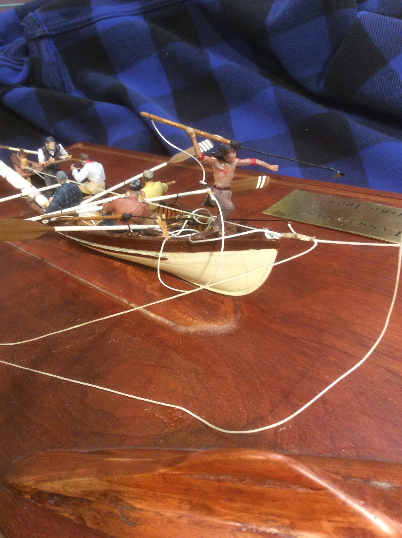
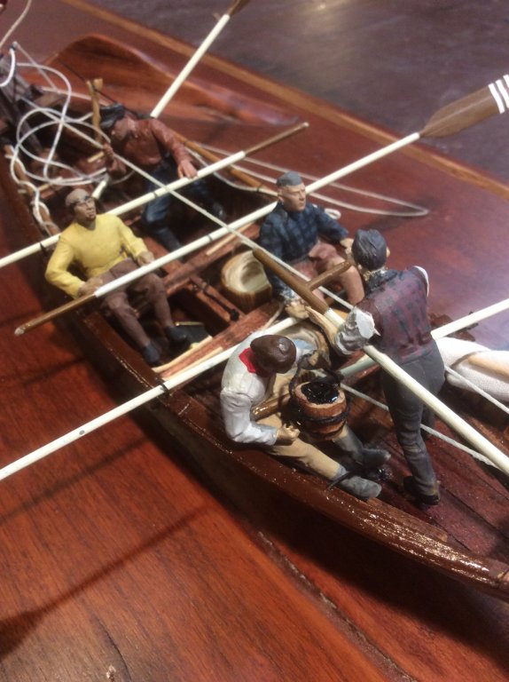
Thanks to both for your kind comments. I now have a much higher respect for those who frequently work with this type figure. Much more difficult than I anticipated to place limbs where you want them and to hold onto such irregular shapes with a forceps while cementing into place. Used a lot of CA de-bonder on my fingers.
-
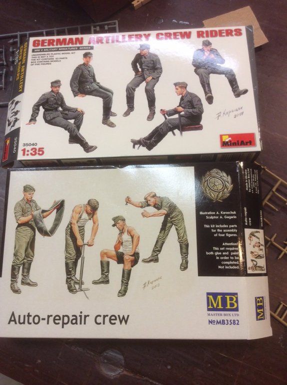
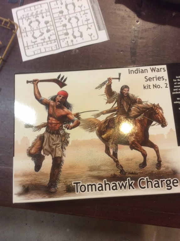
Thought I’d update. Found these guys to modify. And I found this guy to be my Tastego harpooneer from Moby Dick. Turned out ok, I think ... not going in any museum, but my Grandaughter likes it.

- 11 replies
-
- 10
-
-
Hi, Tom Been following your Niagara build with interest, as I am (more or less) scratch building her sister ship, Lawrence. I’ve found you can depend on the advice of Mikiek and 6ohiocav with confidence. On an aside, several times a year we drive through your neck of the woods (White River Junction ... eat at Thyme restaurant) on our trips between Illinois and Maine. Hard to beat that scenery along the Connecticut River valley. Good luck with your build.
-
Roter Löwe 1597 by Ondras71
Srodbro replied to Ondras71's topic in - Build logs for subjects built 1501 - 1750
Absolutely outstanding planking and construction technique! That settles it ... my next build is going to be at a large enough scale to be able to show the planking detail, hoping that I can do half as good as yours. Really enjoy following your work. -
Mike: Maybe the intent of the “really thick” first layer of planking is to permit radical fine tuning of the shape, sort of as a semi-solid hull below you final planking. Just a thought.
-
I’ve been troubled by the looks of pump handles on my models, as well, trying to reconcile a stubby handle with the need for leverage. Ive often wondered if longer handles might not be removable, like capstan bars. Though, I’ve never seen that detailed.
- 362 replies
-
- 3
-
-
- active
- revenue cutter
- (and 1 more)