HOLIDAY DONATION DRIVE - SUPPORT MSW - DO YOUR PART TO KEEP THIS GREAT FORUM GOING! (Only 20 donations so far - C'mon guys!)
×


Srodbro
-
Posts
299 -
Joined
-
Last visited
Content Type
Profiles
Forums
Gallery
Events
Everything posted by Srodbro
-
What type of wood did you use for the cat heads?
-
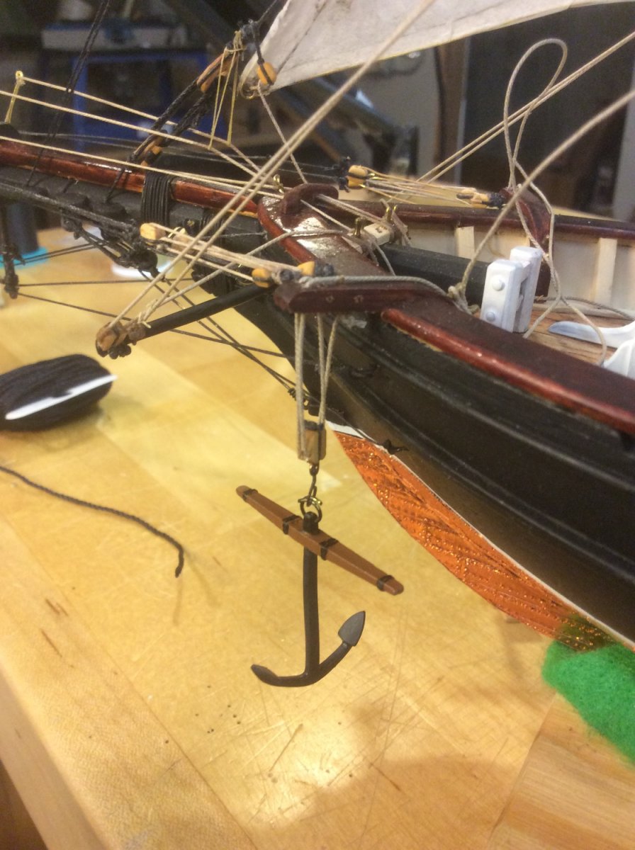
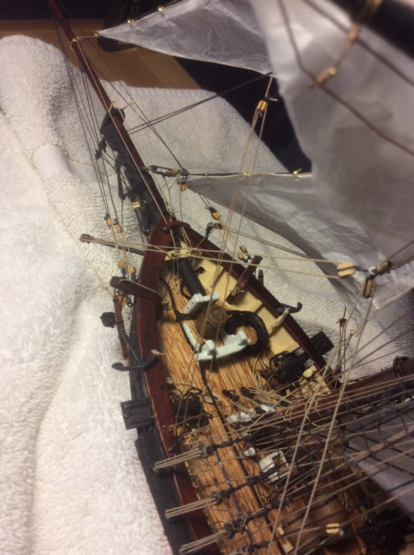
Line ( tack) terminates on the boomkins, outboard of the block. I erroneously terminated mine inboard of the block.
-
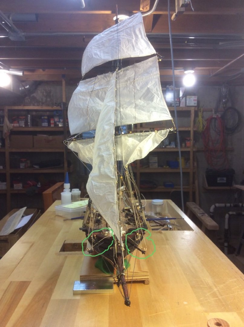
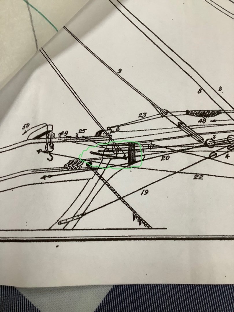
Boomkins for foresail tacks. Circled in green. Not sure how I decided on size shape or location, probably from a different model, but seems to work. It’s hidden pretty well on the plans

- 63 replies
-
- 3
-

-
- Dapper Tom
- Model Shipways
- (and 1 more)
-
SHIFTING TOPMASTS In Chapter Eight of Truelove, notorious landlubber Dr. Maturin describes to another landlubber the process they are observing of shifting topmasts. As I am, myself, a landlubber, I googled several references to learn what this process entails. It’s a lot of work. But, Maturin says: The old Surprise, with a crew that had been together a great while, all men-of-war’s men, was extraordinarily good at it; and I remember that once, in the West Indies, shifting topmasts at the same moment as the Hussar, considered a crack ship, she did so in one hour and twenty-three minutes, Now, it isn’t quite clear whether Maturin is recalling the time for one mast or all three, but either way, that seems a very short time for the effort involved. What do you think?
-
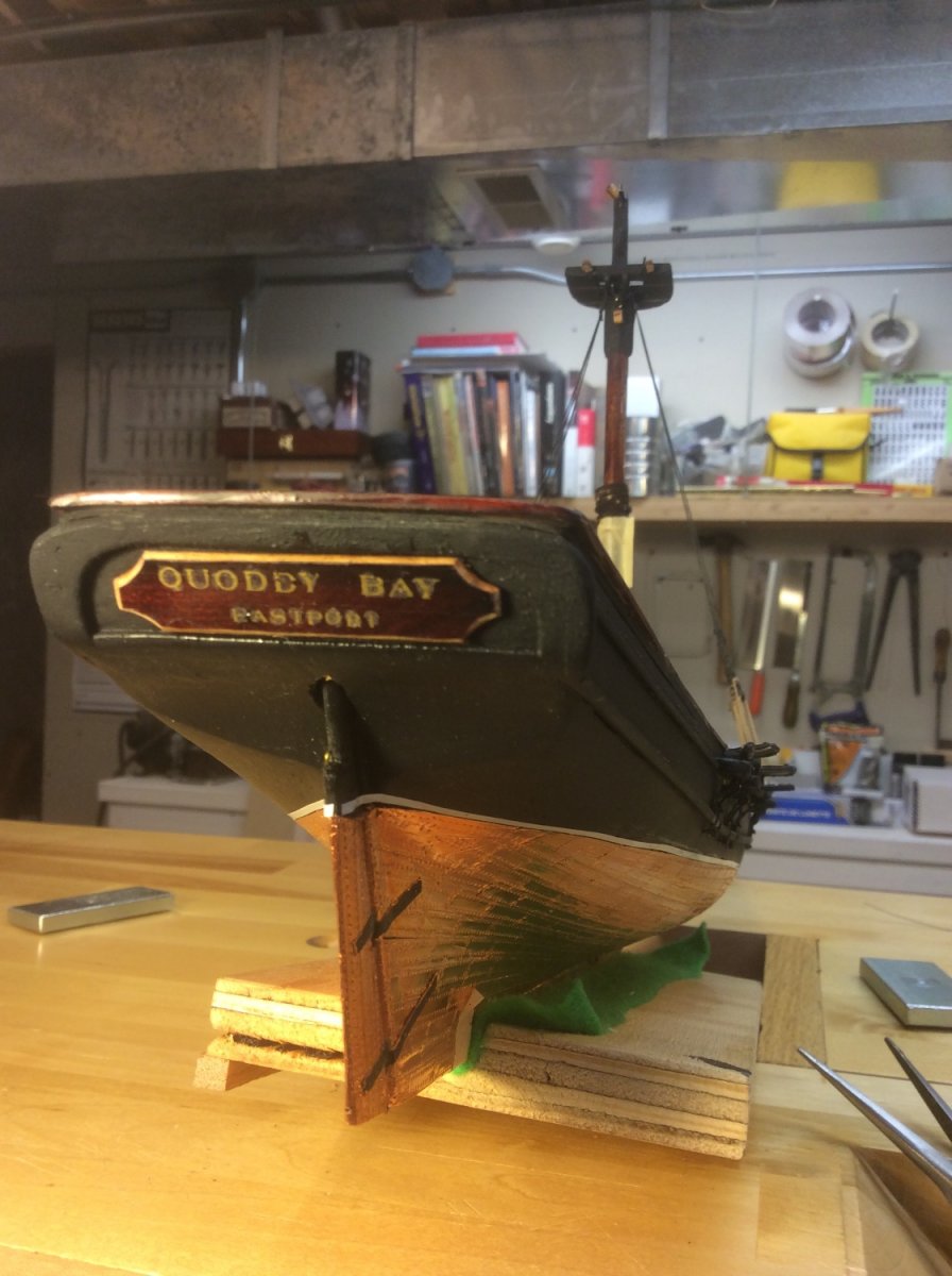
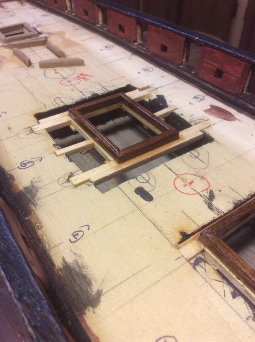
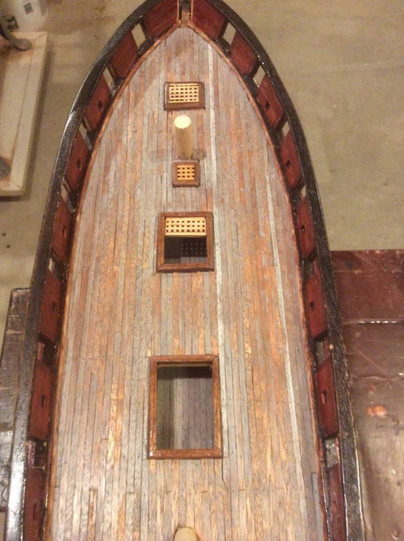
1). Raised letters on transom: Applied a raised name board with flat letters 2). Skylight: On another model I wanted to be able to see down thru the hatches to the deck below. I chiseled out a portion of the hull about double the size of the hatch opening, framed the opening, added the cowelling and planked the lower deck. It turned out well with the shadows highlighting the depth. I suppose something similar could be done for a skylight.


- 63 replies
-
- 6
-
-
- Dapper Tom
- Model Shipways
- (and 1 more)
-
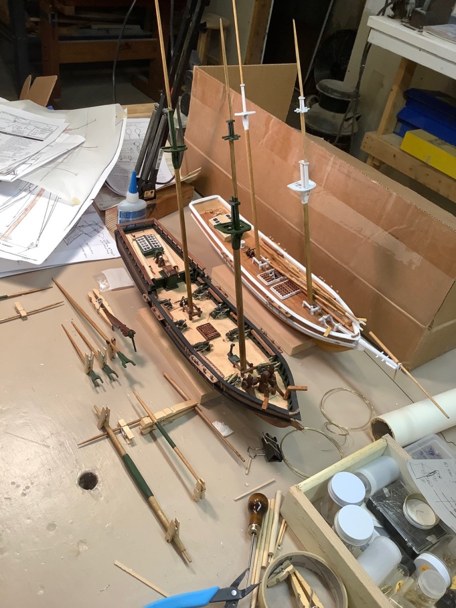
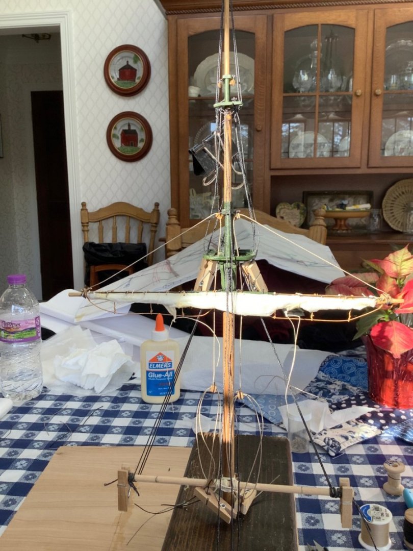
Thanks for your kind comment. I approach modeling as an activity designed to be satisfactory to me, so how picky I am at the details depends on the day I am doing them. Frequently, they don’t pass muster the following day, but as another member states, “ the wood is forgiving “. I initially spent hours carving, sanding, filling, sanding, filling, etc. ad naseum trying to get the hull shaped just right, tossing the whole thing into the trash, retrieving it, and continuing on another day. In the end, I decided that wasn’t nearly as important to me as getting into the satisfaction of the rest of the build. So, my tip would be: If it becomes a burden, it’s no longer a hobby. Also, remember that the model is an illusion. Unless you’re looking at the model from directly below ( and not many people do that) you can’t tell if the hull is exactly symmetrical. I have learned that Model Shipways solid hull blanks are machined more symmetrical than others are. This model has been around for many years and instruction sheets have been revised several times. The first model I bought I got on eBay, and it was an unbuilt kit from many years ago .. the instructions were printed on one 8 1/2 x 11 sheet, rather than the multi-page booklet that comes in the kit now. But, the plans appear the same. Consequently, there might be some instructions that don’t exactly match the plans. So, you may need to use some of your own woodworking intuition to get where you want to be. As far as getting the masts located as desired, I learned to depend less on the hole in the deck and more on adjusting the shrouds and stays … maybe make the holes a bit too big. The general rule I read about for rigging sequence is “Inboard-to-outboard and fore-to-aft. “ Belaying a line on a pin on the fife rail after the shrouds and ratlines are in place ( that is, doing all running rigging after all standing rigging) can be challenging, tho that’s what I did on my first build. On my current builds I’m experimenting with installing rigging as much as I can onto the masts and spars off-ship prior to stepping the masts into the hull, then firming up standing rigging, then tightening up on running rigging. Like I say: I am experimenting with that process. Here’s a pic We shall see how that works. Might wind up in the trash some day. Ok, just one more tip then I’ll return your log to you: I could never get the footropes on the yards to look good using any sort of thread .. they just wouldn’t hang right. I found using fine brass wire and then carefully painting it had a much more pleasing effect. Good luck.
- 63 replies
-
- 5
-
-
- Dapper Tom
- Model Shipways
- (and 1 more)
-
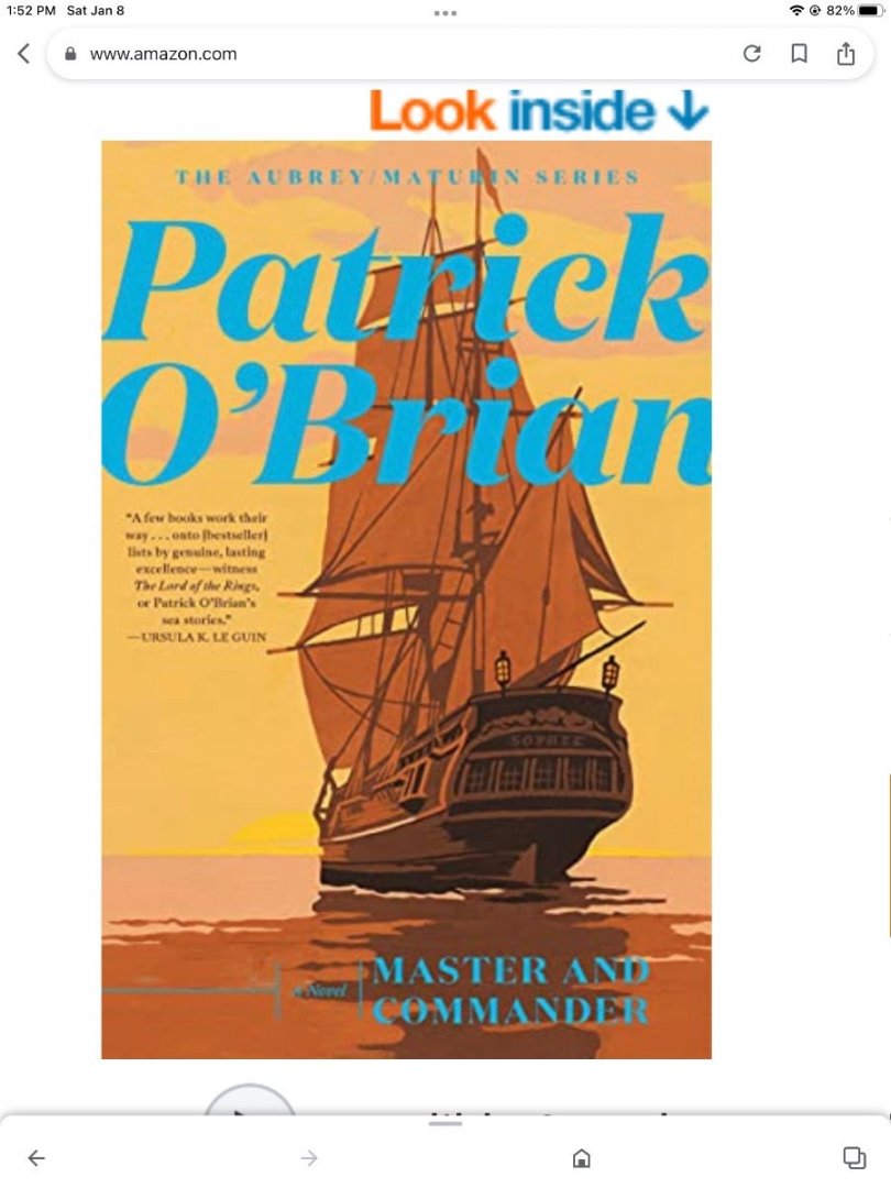
I am into my fourth circumnavigation of the series. My opinions of each book seem to change with each trip. Right now, I’d rank them as follows: First: Master and Commander. Just can’t beat that first meeting in the music room, and the initial development of the primary characters. Holmes and Watson, Quixote and Sancho “ ain’t in it”. Also, immerses us into that long gone world, gently, without insulting our intelligence, in fact subtly challenging it. Second: Post Captain. Introduction of the next two most influential characters, Sophie Williams and Diana. And, reminds us that the two heroes have a life ashore as well with a set of desires and aspirations which affect them as much as the one at sea. Third: HMS Surprise: Introduction of the next most important character: Surprise. IMHO Surprise is more than a vehicle to carry the heroes to their adventures and back, but is a character in her own right, with whom other characters, and readers, become emotionally attached to. While it is hard to separate the first three, the next kinda stand alone. Fourth: The Commodore ( 17th book). I think this book ended the development of all the major characters, tied up all the loose ends with the deep, dark force that was nagging Jack and Stephen’s fortunes, and leaves the way open for Jack to get his flag … which everyone knows is going to eventually happen. I think it might have been intended by O’Brian to be his last. It would be interesting to know what was going on in POB’s life at the time he wrote it. It ends with the perfect line: “ Stephen, you must never go to sea again.” Also, the books that follow either don’t mention many of our familiar shipmates, or ends them in ( to me) an unsatisfactory manner, to no purpose. But, I am coming up again to the last several novels, and could change my mind.
-
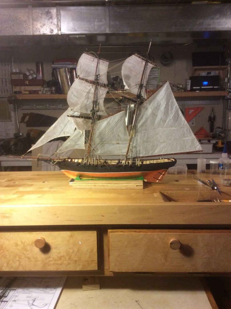
Will be following with interest. I love that kit. It was my first Model Shipways build. Since it is of a fictitious boat, you can do anything you want to it and nobody can criticize you for being historically inaccurate. Here’s one I finished several years ago, and two more variations on the theme in progress Have fun.

- 63 replies
-
- 6
-
-
- Dapper Tom
- Model Shipways
- (and 1 more)
-
Ouch! I feel your pain. On the other hand, I will be interested to learn how you fix it. Good luck.
-
If you like the books, checkout the podcast “The Lubbers Hole”. Reviews all the books, with some expert commentary and interviews … latest included interview with Geoff Hunt. Great listening while building.
-
Yep … that’s the true guide, no matter what Hunt ( and I really love his art) or others may show, you gotta be true to O’Brian. By the way Hunt didn’t start illustrating Aubrey-Maturin books until many years after the first books were published (at around Book 11, I think, when O’Brian got a new publisher), then he went back to paint covers for the earlier ones. Here’s a pic of an earlier cover with Sophie on it. 5 windows! Guess this guy didn’t read the book.
- 341 replies
-
- 3
-
-
- Sophie
- Vanguard Models
- (and 1 more)
-
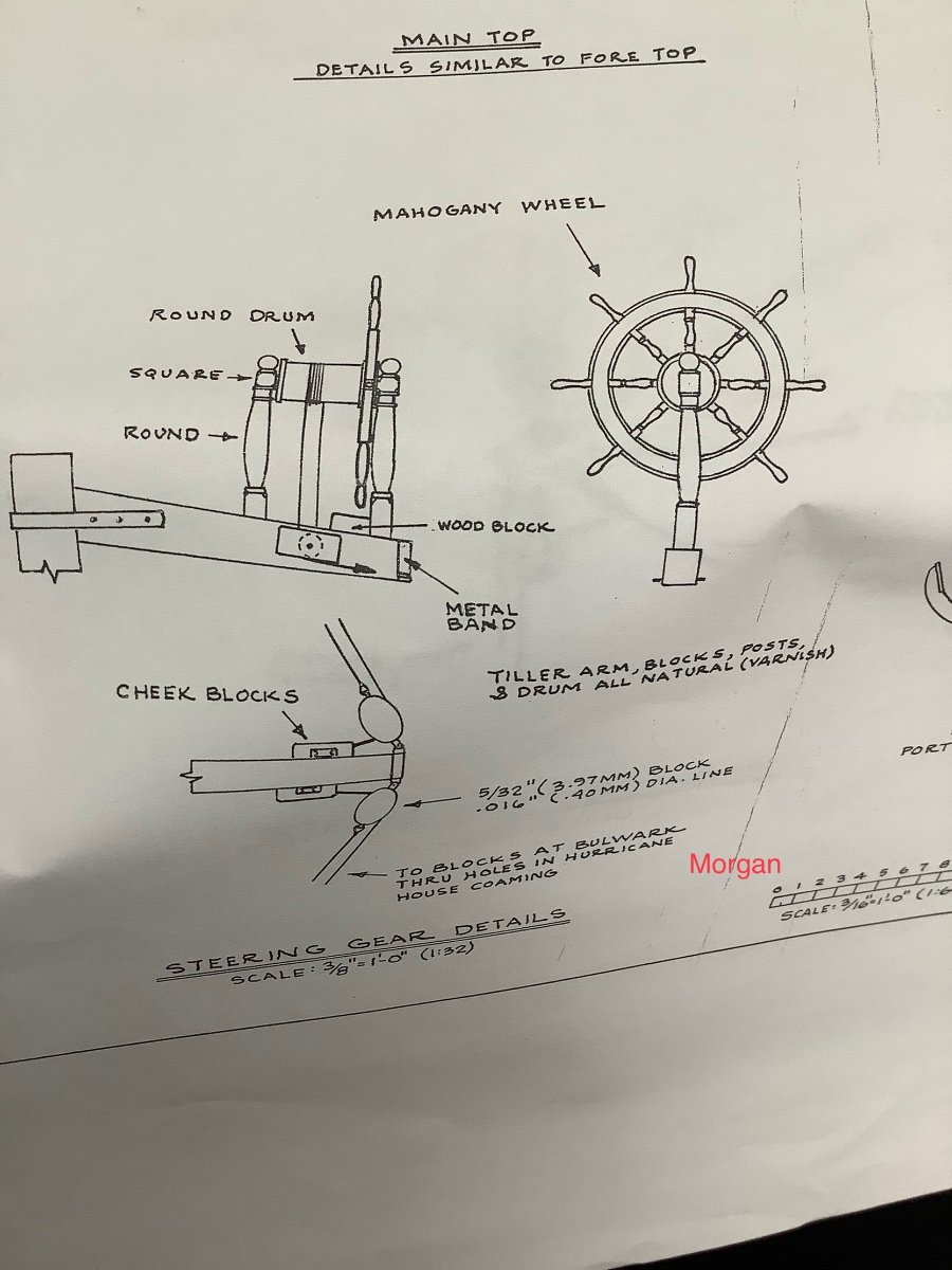
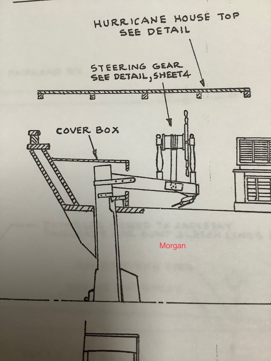
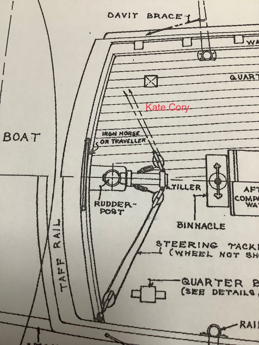
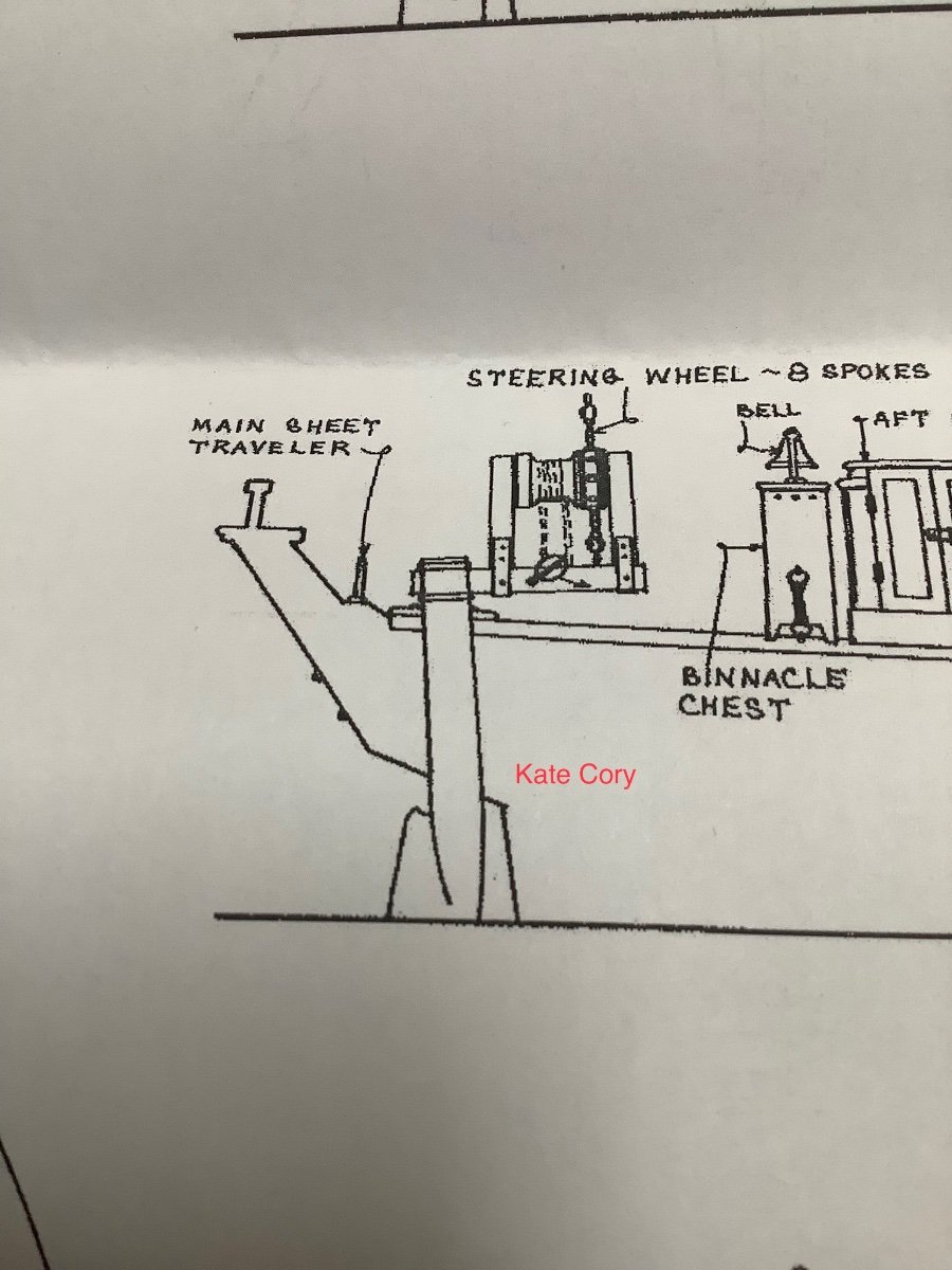
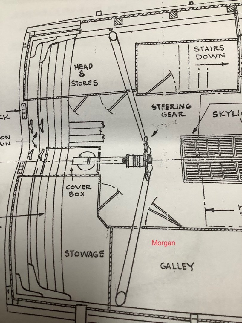
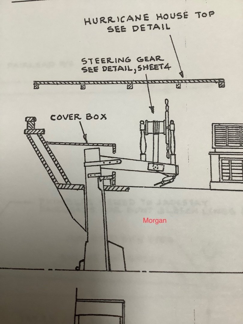
There is a solution to the tiller-wheel issue that satisfies both. The pics below are from Modelshipways plans for Kate Cory and Chas Morgan. Both show a wheel mounted on the tiller. Not sure this solution would be period appropriate, since the action in Master and Commander takes place in 1801, and both of the whalers with this detail are from 30 to 50 years later. But, who knows? Patrick O’Brian had a couple other anachronisms in the Aubrey-Maturin saga, but not many. But, it seems such a “strange” ( to landlubber me) arrangement might have been commented on by O’Brian, like the elm pump. On the other hand, the pump allowed further development of Maturin’s character, whereas this wheel-tiller arrangement might have been commonplace enough to not warrant comment.


- 341 replies
-
- 3
-
-
- Sophie
- Vanguard Models
- (and 1 more)
-
I like that interpretation better than mine. 35’ or so always seemed to me to be too short for Sophie’s beam.
- 341 replies
-
- 2
-
-
- Sophie
- Vanguard Models
- (and 1 more)
-
At the risk of getting too granular: Aubrey was a young, ambitious lieutenant seeking his fortune in prize money. His first discussion when undersail in his first shake-down of Sophie was with the sailmaker, asking if he could get more canvas on the mainsail. Sailmaker said No, whereupon Jack focused on the yard itself. Here are, I think, the relevant passages: Jack grunted and returned to his staring at the mainyard, a piece of wood rather more than thirty feet long and tapering from some seven inches in the slings, the middle part, to three at the yard-arms, the extremities. ‘More like a cro’jack than a mainyard,’ he thought, for the twentieth time since he first set eyes upon it. He watched the yard intently as the force of the wind worked upon it: the Sophie was running no faster now, and so there was no longer any easing of the load; the yard plied, and it seemed to Jack that he heard it groan. After pushing it to the point of springing, Jack returned to the dockyard, obtained another yard, and returned to his ship, where his carpenter said: ‘Now that is what I call a real spar,’ said Mr Lamb, peering lovingly over the side at the yard. ‘Never a knot, never a curl: a French spar I dare say: forty-three foot as clean as a whistle. You’ll spread a mainsail as a mainsail on that, sir.’ But after hoisting it up, the head of the dockyard said: ‘It will never do, Captain Aubrey,’ called Mr Brown, hailing over the quiet evening air through his trumpet. ‘It is far too large and will certainly carry away. You must saw off the yardarms and half the third quarter.’ The carpenter reappeared with a saw and a rule. ‘Have you a plane there, Mr Lamb?’ asked Jack. ‘Your mate will fetch you a plane. Unship the stuns’l-boom iron and touch up the ends of the stop-cleats, Mr Lamb, if you please.’ Lamb, amazed until he grasped what Jack was about, slowly planed the tips of the yard, shaving off wafers until they showed new and white, a round the size of a halfpenny bun. So, the original sprung yard was at least 30’ long and the replacement was 43’ long, less the yard arms ( maybe, say 18” per side) and less 1/2 of 1/4, or 1/8 of 43’, say another 5’-2”, so down to about 35 ft long, but probably larger diameter than the original. How much more came off with Mr. Lamb’s plane to get to the size of a halfpenny bun, would have to be answered by a Brit. Allow me to add another quandary: Patrick O’Brien refers several times to the helmsman at the wheel, at least once having to firmly grasp the spokes of the wheel. From all the detail I’ve seen, HMS Speedy was steered by a tiller ( I’m not sure what is in the kit). So, HMS Sophie: Wheel or Tiller?
- 341 replies
-
- 5
-
-
- Sophie
- Vanguard Models
- (and 1 more)
-
Just a quick follow up and I’ll recede into the background: The original main yard that Aubrey was not satisfied with was described thus: Jack went to the rail and looked sharply at the sea running by, the long curve as it rose after the hollow under the lee-bow: he grunted and returned to his staring at the mainyard, a piece of wood rather more than thirty feet long and tapering from some seven inches in the slings, the middle part, to three at the yard-arms, the extremities.
- 341 replies
-
- 2
-
-
- Sophie
- Vanguard Models
- (and 1 more)
-
Perhaps it is as supplied in the kit. There is a description of the yard that to Aubrey was too small, so you may be able to judge from that. It is clear that Jack disliked the Main yard on Sophie when he first took command of her, and pushed her hard until the spar sprung. He got another from the shipyard, maybe a spare foretopgallent yard from a ship of the line, but alas the yard master said ‘It will never do, Captain Aubrey,’ called Mr Brown, hailing over the quiet evening air through his trumpet. ‘It is far too large and will certainly carry away. You must saw off the yardarms and half the third quarter.’. But among the dimensions Mowett recites to Maturin, the main yard is not included … in fact, Mowett says he will have to measure it. I think we never do find out the final size.
- 341 replies
-
- 3
-
-
- Sophie
- Vanguard Models
- (and 1 more)
-
Just found your log. Love your approach. I should like it of all things to learn how you dimension the main yard. Have fun.
- 341 replies
-
- 3
-
-
- Sophie
- Vanguard Models
- (and 1 more)
-
Viking ship rigging ... What’s this called
Srodbro replied to Srodbro's topic in Masting, rigging and sails
What?? “ Upside down?” -
I recall rolling mine out, wetting it and hanging it, heavily weighted, from overhead joists in the basement to dry.
-
Thanks for responding. So, it appears the consensus is the rigging was driven by where the vessels would be spending their time most. I can dig that, but it also seems to me that there might be a connection between the style of rigging and the particular need for whalers to provide a steady platform whilst butchering the whale. I’m thinking a large amount of fore-and-aft canvas abaft the beam would contribute to the ability of the ship to be sailing closer to the wind during that work. That thought would apply to the change to Morgan, but not to the change to Kate Cory. Perhaps the similarity in rigs is, after all, just coincidence.
-
I’m preparing to dive into builds of Kate Cory and Charles W Morgan. I have read that Kate Cory started life as a schooner, then was re-rigged with square sails on the formast, becoming a brig(antine). The Morgan started life as a three masted square rigged ship, then changed the Mizzen mast to fore-and-aft rigging, becoming a bark. Both whalers, then, having morphed into vessels with fore-and-aft rigged aftermost mast. My landlubber model shipbuilder question: Is this arrangement inherently advantageous for a whaler? Why?
-
I did a quick search but I cannot find how I can tell when my membership will expire. can you help me? Thanks.
-
A question about your planks: Is the shape of an individual plank the same from stem to midship and from midship to stern? Love your build. Trying to figure out this new emoji thing to give a “like”.
-
Just a tip I found useful : Several of those double blocks eventually have buntlines run thru them. I found it very useful to run a few temporary lengths of line thru those blocks now which can later be used to reeve the buntlines ... running them later, once your mast is mounted, the yard hung below, and shrouds and stays supporting the mast are in place, is a really tough access puzzle.
-
Ah-HA! Great thread, Jack!