


hervie
-
Posts
68 -
Joined
-
Last visited
Content Type
Profiles
Forums
Gallery
Events
Posts posted by hervie
-
-
Paint is not the main subject of this log. So I apologize for one more paint post. However the subject of using house paint for models came up, so I’d like to put it to rest.
First of all, acrylic house paint is not formulated the same as model paint. House paint is formulated for … well … houses

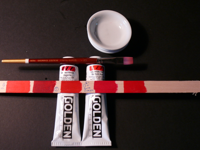
Nevertheless I trotted to the Benjamin Moore paint store and for $2.5 each I got the two acrylic samples shown below. (If these were model paints, each sample would cost about $450)
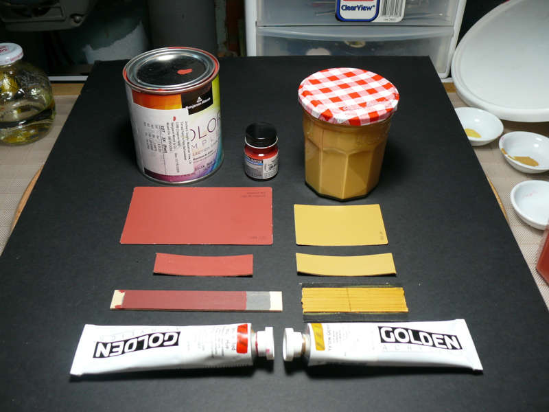 The base for these samples is called ‘latex’. But there is no latex in ‘latex’ paints. There is mainly acrylic resins and vinyl. Here is a link that talks about this.
I liked the coverage and handling characteristics of these paint samples. Surprisingly, they were easier to apply consistently than the Golden Acrylic paints. And very easy to match colors too.
But how durable are they? I doubt house paints are designed to last for as many years as acrylic artist paints.
If you google “latex paint in models” you’ll get some interesting links for airplane modelers. Pretty good opinions too. For for wood model ships?
Nada.
So the jury is still out, and I haven’t made up my mind as to whether to use these samples or not. What I do know is that I need to get going with planking!
-
ca.shipwright, thanks for the tips. I've worked with several types of paints - oils, acrylic, water colors and gouache -- but on paintings, not on models. On models I've only used Testor's lacquer paints.
Your source for acrylic paints is pretty clever . I would not have thought of it and have to try it.I have a couple posts on this log using artist quality acrylic paints. I went to the hobby shop and got one tiny bottle of Model Master's acrilic paint for $4 to compare. Not cheap! Your source is much cheaper. I'll compare the paint with the others for handling, coverage, etc.Thanks again. -
EJ_L, thanks for your timely advise.
I’m more into overall looks than scale accuracy. For example, the kits supplied quarter badges are horrible, so unless I can come up with a good replacement I will skip them all together. Nobody here will know they are missing.I don’t think the tree nails on a painted hull will be noticed or missed either, so your advise puts the nails on the coffin (pun intended )Any advise on painting pitfalls lurking down the road? -
Tree nails on a painted surface.
Big decision time. To paint the exterior planking yellow ochre or not.
I was going to use stain but couldn’t get good results on test strips. Then I saw the Syren build of MD11pilot (page 3, post #51), and the Niagara build of 6ohiocav (page 1, post #1), and wow! Forget about staining!
But painting is more involved than staining IMHO. What worries me are future implications in view of the outer hull details yet to be addressed. I’ll have to break my rule of not using glue on top of paint.
But man I like the painting effect!
So I’m proceeding with it. If someone thinks it’s a mistake, now is a good time to raise the alarm …
Meanwhile the first implication is that I’ll have to paint the planks before installing. Just the first coat to take care of the edge around the gun ports.
The entire paint job takes three coats, with very fine sanding in between.
That leaves the tree nails to figure out. Here is what I came up with:
First, the tools (not shown are zillions of toothpicks):
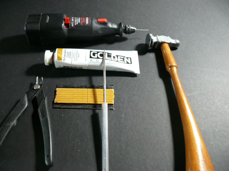 The paint used is Golden Acrylic Yellow Ochre
Two coats of paint were applied, sanding with 320 grit film in between coats. Plus emphasizing the space between planks with the pointy tool shown above.
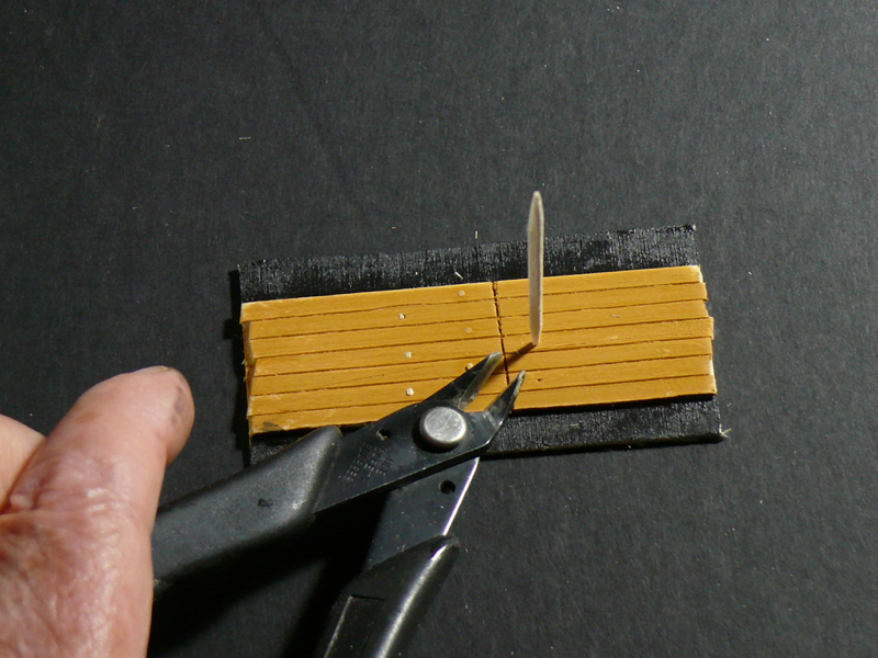
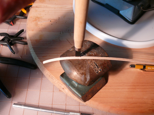
That same tool is used to create a hole for the tree nail. Tapping gently with the hammer.
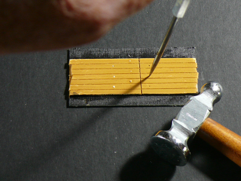
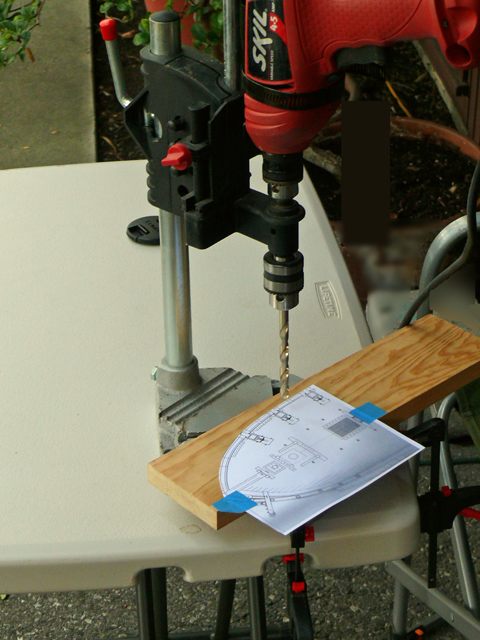
Then the drill with a #60 bit is used. (The tree nails shown are no good, they were practice nails)
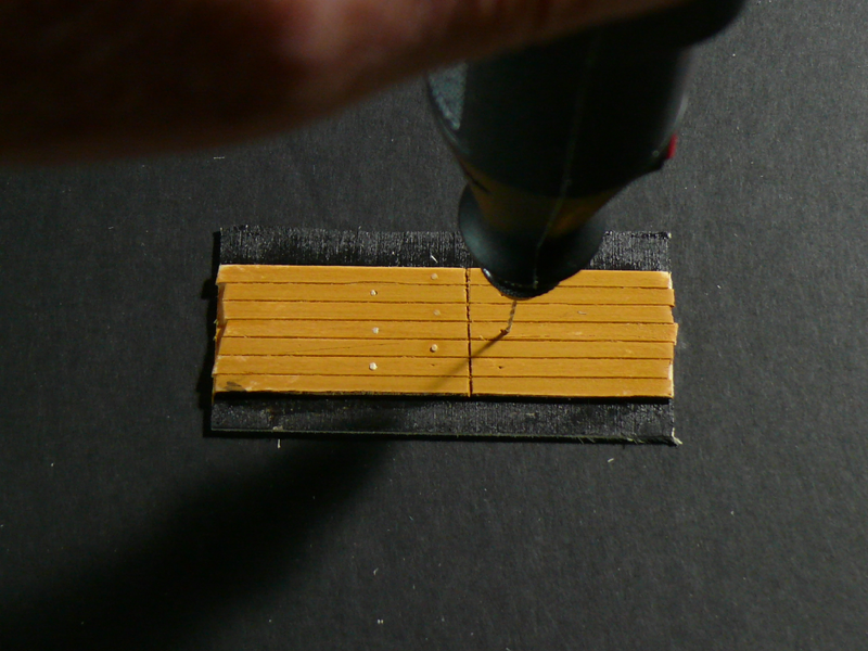
A tooth pick was inserted and clipped at the base. No glue was used.
 Then the remnant was hammered in.
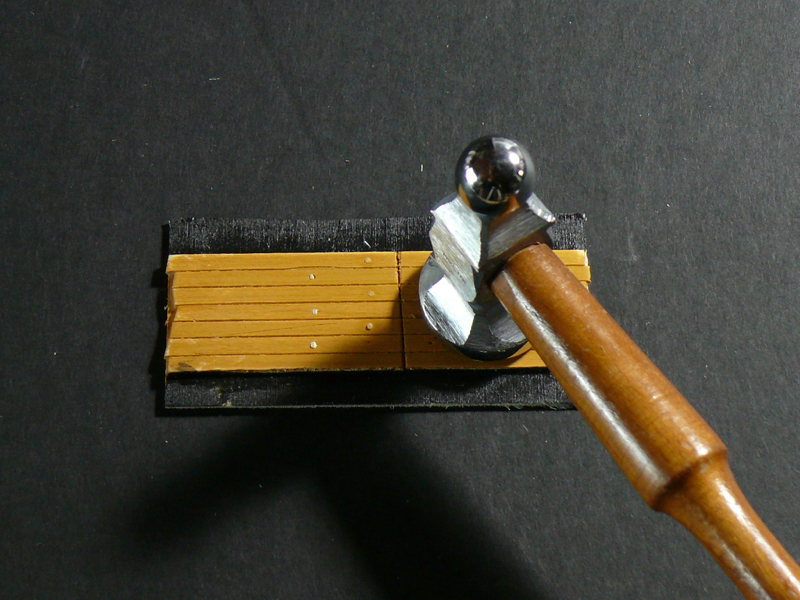 Here is the result before the final paint coat:
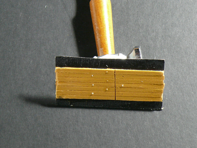 And here it is after.
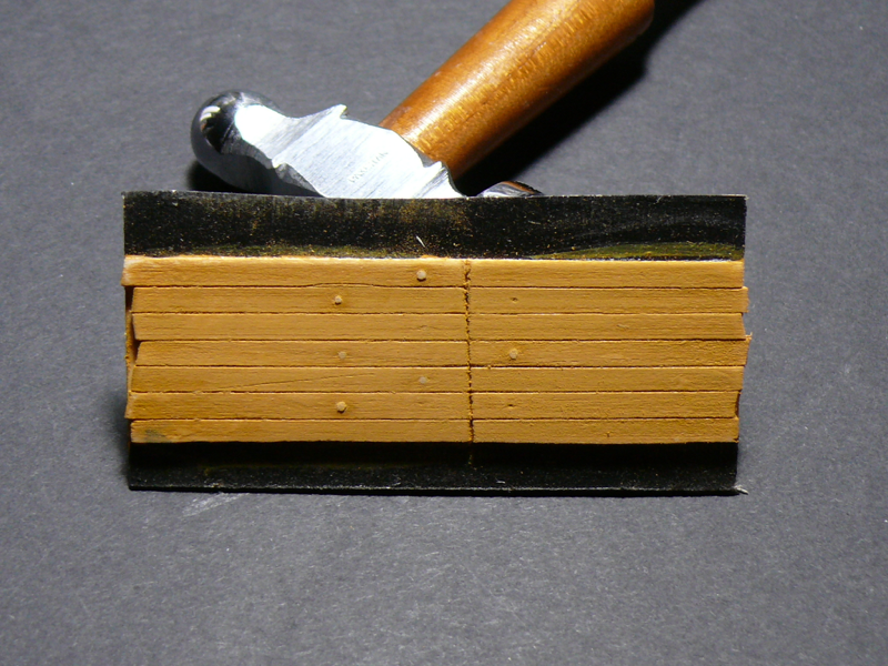 I took this photo with the light shinning almost parallel with the planks. This emphasizes the 3-D aspect of the tree nails, which really is much more subtle than what is shown.One immediate observation is that the tree nails should be smaller. Obviously I need more practice, but that’s the plan anyway.
What do you think? …
- GrantGoodale and EJ_L
-
 2
2
-
I love the detailed step by step illustrations of your log. Thanks for taking the time. And I do like the yellow ochre paint too. So much so I plan to adopt it in my Syren build. Hope we'll hear from you soon. .../hervie
-
dgbot, thanks for the tip. That's a way I would feel comfortable with, but it would not work in this case because of the rabbet around the gun ports.
ca.shipwright, glad you got a good camera. Read the manual and experiment. And forget about 'skill levels'. We learn from all skill levels. You should see the pile of dead wood I've been creating lately . Scott Adams, the creator of the Dilbert cartoon strip says it well: "we learn from failing, not from succeeding".
-
Sal, thanks for detailing your process. Unfortunately patience is not one of my virtues. (I'm in the wrong business, I know).
Darrel, Wow! Way too generous! I'm afraid my modeling skills are second to many on this site. About the log, I enjoy it. I begin with an advanced, friendly camera (the iPhone and equivalent wont do), and take pictures along the way. While doing so I build the story in my head, and tell it with as few words as possible. Easy.- Ryland Craze and EJ_L
-
2
-
Excellent as usual. I'll also be getting the wheel kit when the time comes. There's no point in using inferior castings that detracts from a model built with so much care.
- CaptainSteve and Gahm
-
2
-
The second plank
The second plank is more challenging because it encroaches on the gun ports.
If I could choose one way of doing the entire upper planking job, I would choose Sal’s way (_SalD_): all planks glued in one piece, then the the gun ports cut out with a #11 blade. But I can’t. I can’t cut a straight line if my life depends on it!
Cutting with the blade across the grain takes me more than a dozen passes, and the result is a mess.
Cutting with the grain invariably splinters the plank.
And this while practicing on a plank not even glued to the ship.
Sal, how do you do it?
Then I tried Dirk’s way with a chisel (Dubz). Even worse.
Dirk, how do you do it?
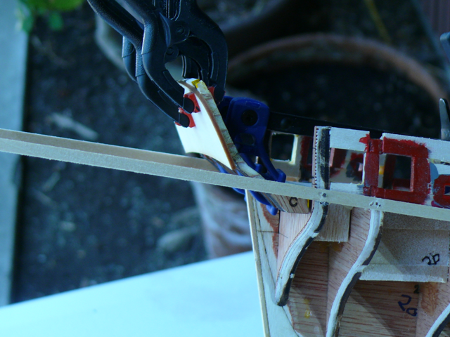
So I tried another of hervie’s specials: using the table saw. Here it is with a practice plank.
Raise the blade to the desired depth and cut one end of the gun port opening.
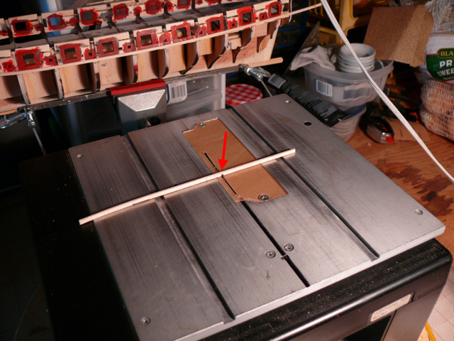 Then cut the other end.
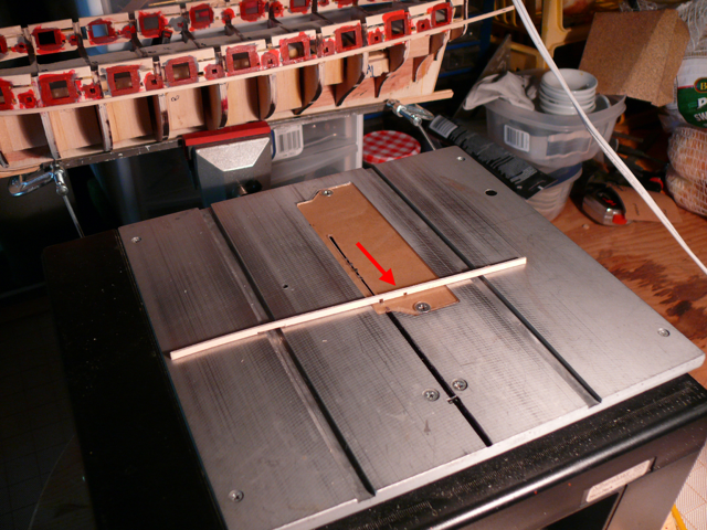 and move the plank back and forth across the blade to complete the gun port ‘slot’
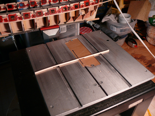 Pretty clean result.
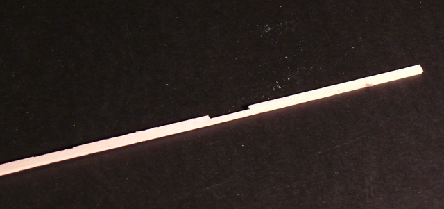 Even when the remaining part of the plank becomes very thin, it will not break.
And because the blade height can be set on a practice plank, when it’s time to commit to the ‘real’ plank there is no guessing.
That’s the theory …
Which I put to practice.
First I marked the gun ports and sweeps for the entire length of the plank. This better be done in one shot because otherwise it’s hard to maintain alignment.

Then I cut the openings where necessary adding 1/32 to the markings for the rabbet.
IMPORTANT. For the first pass with the table saw, the depth of the blade must be set conservatively assuming that more depths will be needed for the slots. The final pass can be done with the saw or with files.
It is easy to test results while this is in progress by putting the plank on the ship.
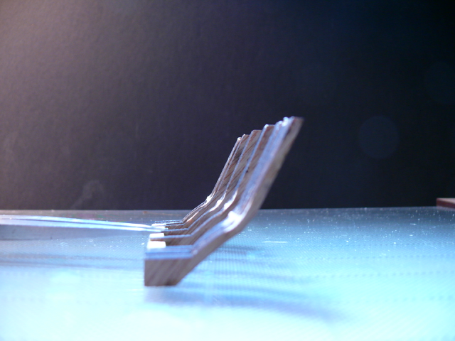
Here is the first pass for the entire second plank..
And here is the plank against the hull to compare results. The plank is still not glued to the hull. More small cuts are needed but these can be done with the #11 blade.
You will notice I don’t miss an opportunity to use the power tools. I depend on them. Primarily because I’m supper lousy with hand tools.
Contrast this with how Harold Underhill, the English author of the classic book shown below, constructed his model in 1958. On a kitchen folding table with no power tools. His entire tool set fit in his pocket!
Pretty humbling ...
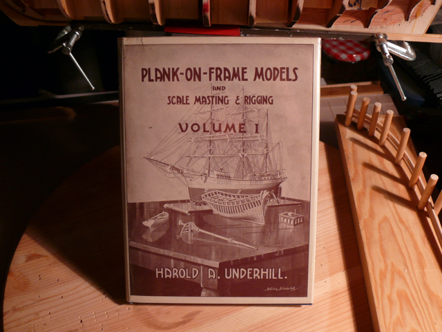 (I am lucky to have both volumes of this book which has been out of print since 1978. They are collector items. Every so often they appear on eBay).
My next posting, except for another about color, will be for the completed upper planking. So it’ll be a while.
Till then, Sayonara.
-
Thomas, EJ_L, ca.shipright, Thanks for your generous comments.
EJ_L, I don't plan to use a single board for the area between gun ports. I tried, but cannot come up with a good way to trim the boards around the gun ports. So I'll be using another hervie special. I'll have a post on that today ('the second strake').ca.shipwright, I am aware about acetone. I'm just impatient sometimes. But thanks anyway.I just don't like CA, although sometimes there is no other alternative. Needless to say I plan to use it as little as possible. -
-
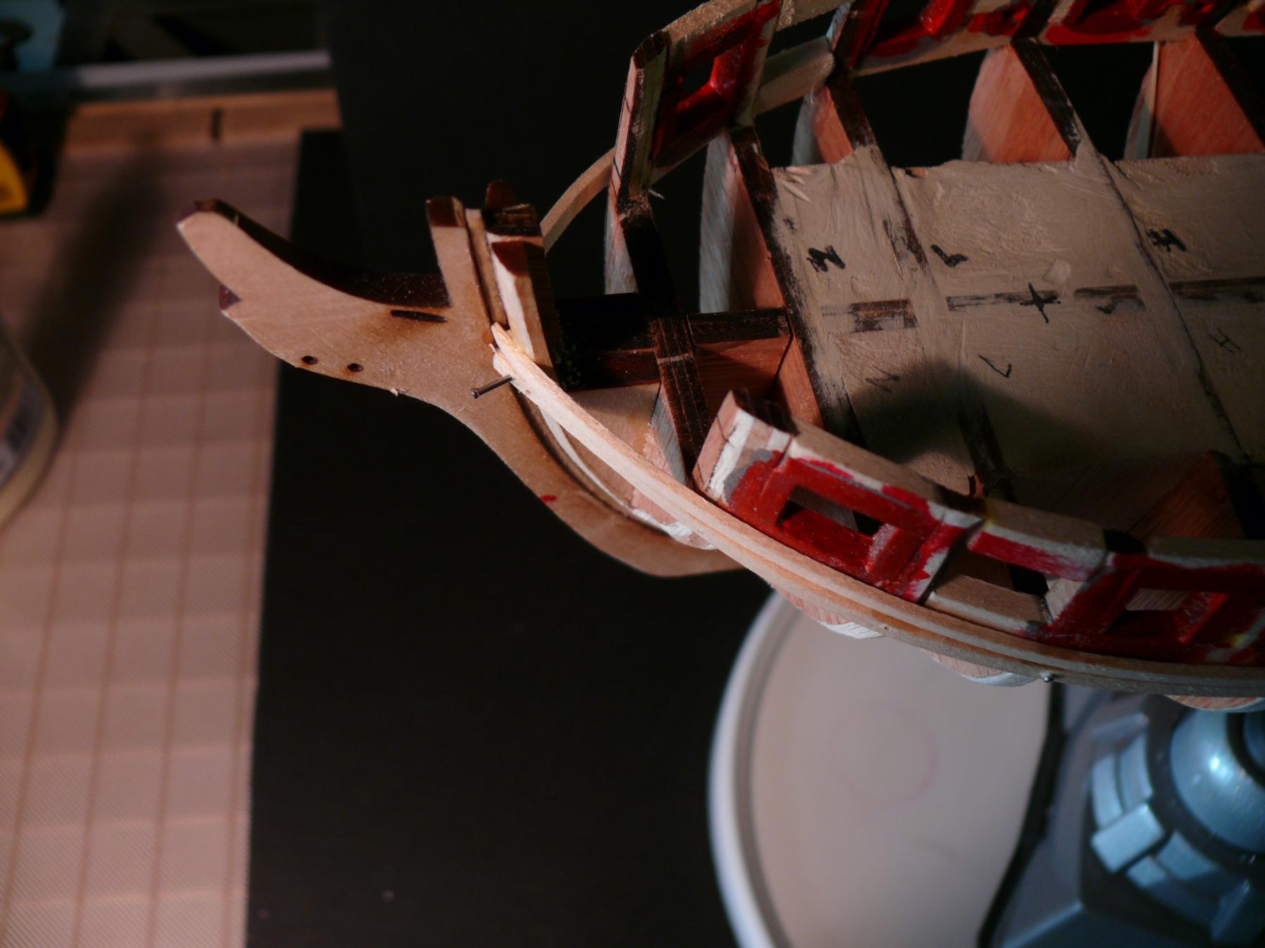
First strake above wale
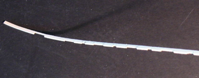
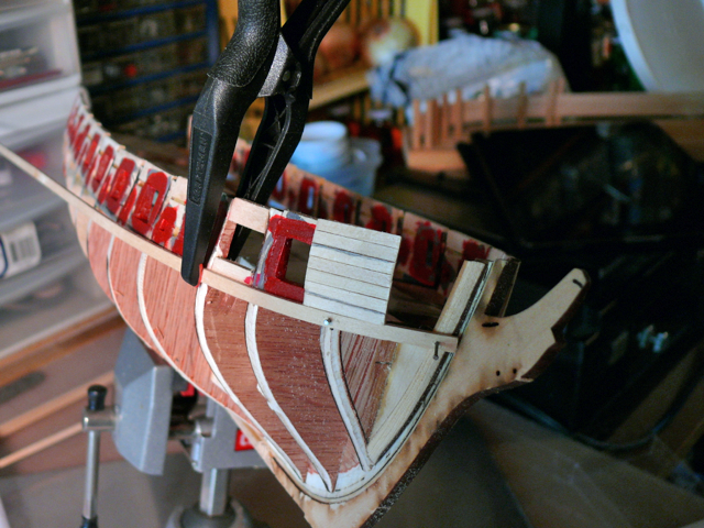
After removing the Stern I glued the fist stake. in one piece as opposed to in segments. Later I’ll cut notches to simulate the boards of the strake, like Sal did (_SaiD_).
I used CA instead of PVA. Bad choice! (see below)
I got a nice curve at the bow. That’s what I referred to as a ‘natural curve’ in a previous post. I couldn’t produce that curve by shaping fillers by hand.

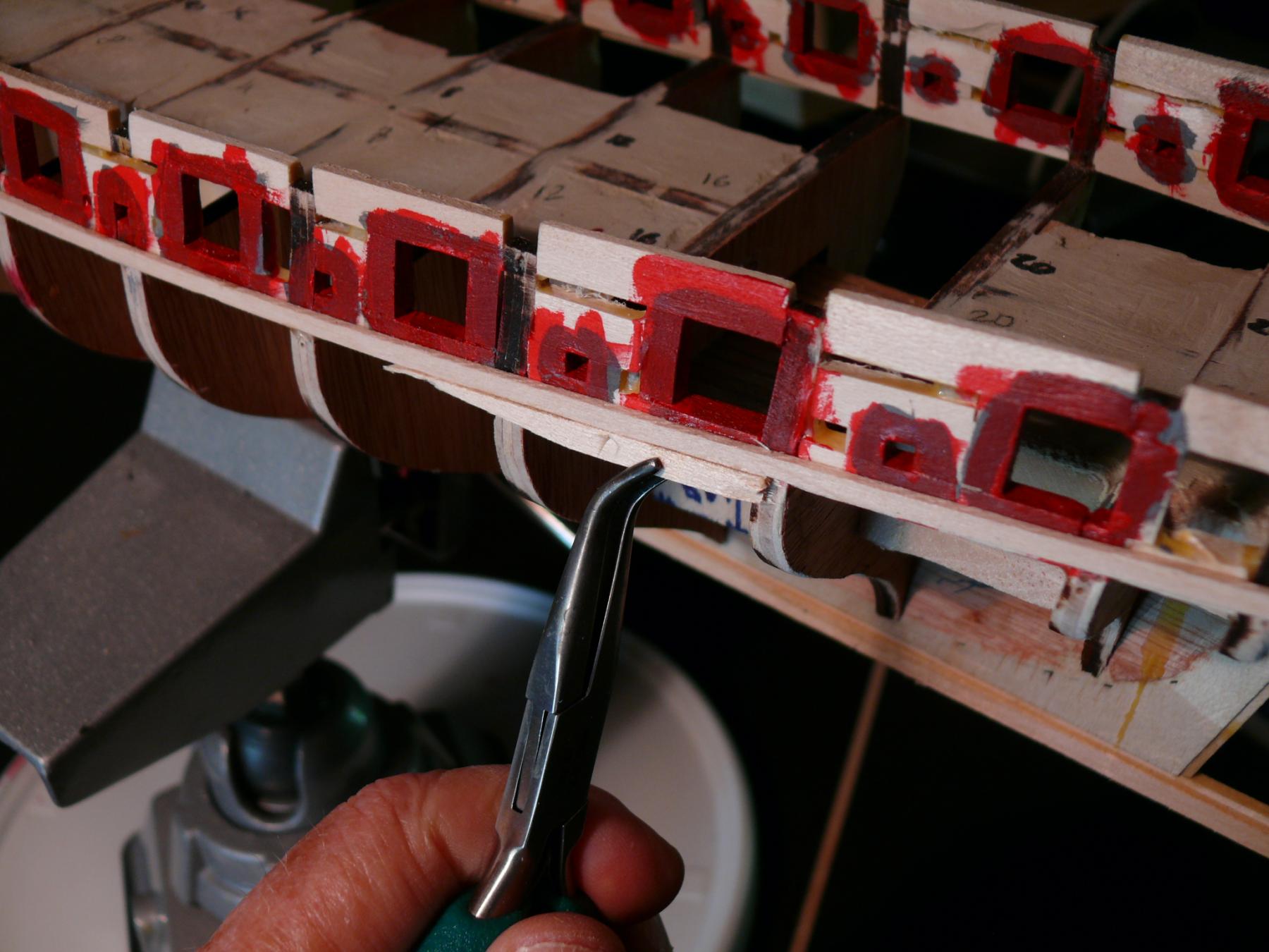
Alas when it came time to remove the temp wale, the CA has spread to the wale producing a nice bond with the strake. I forgot what a nasty thing CA is. I had to use pliers to remove the wale. Will have to do some cleaning later,
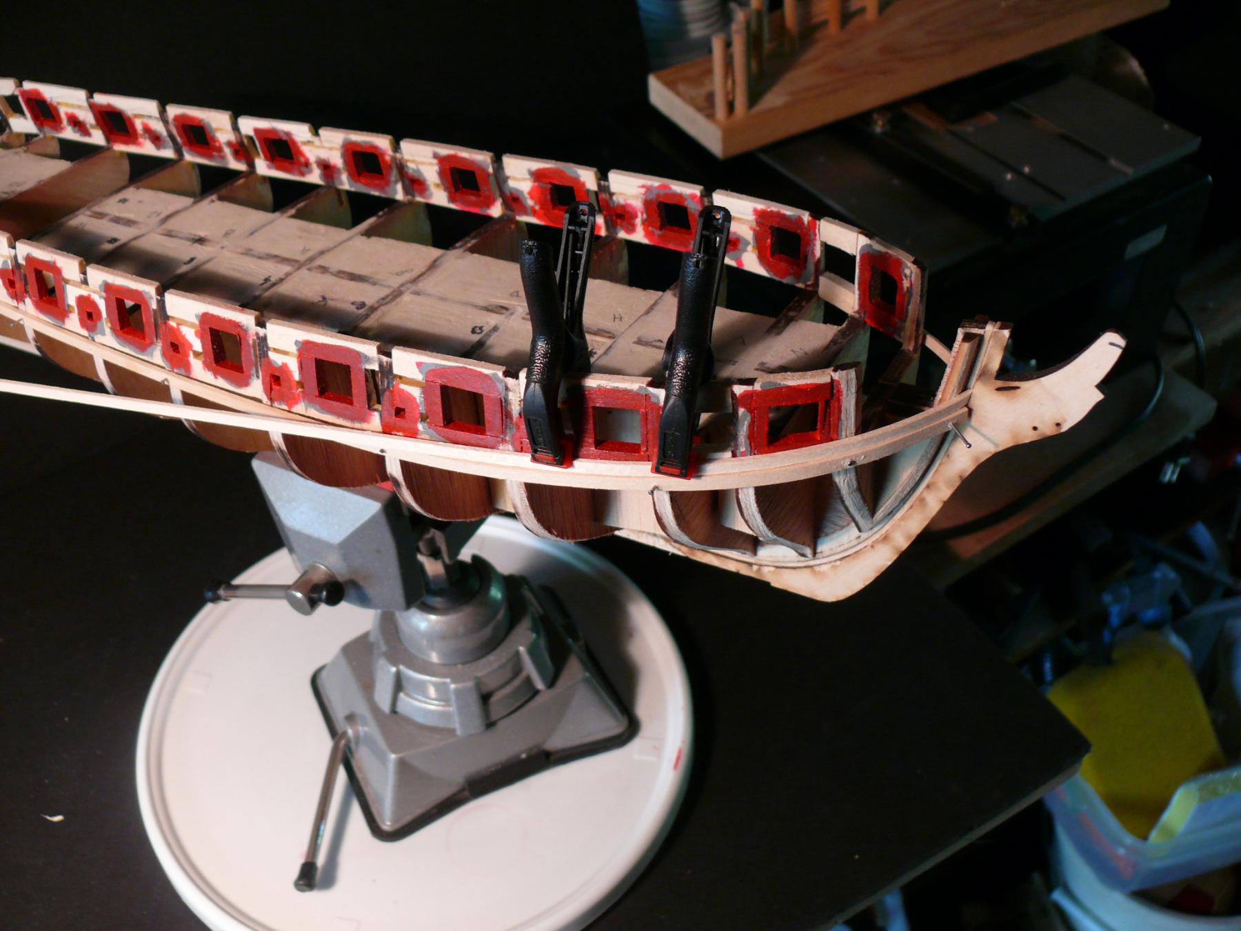
 Here then is the first strake minus the wale.
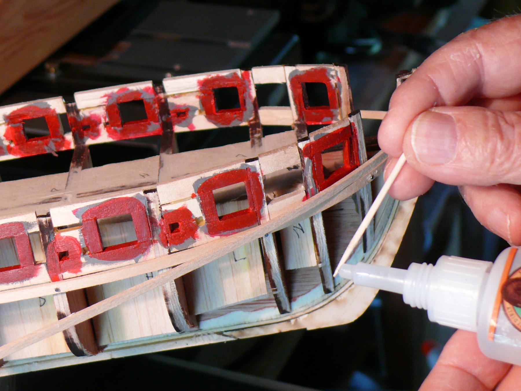
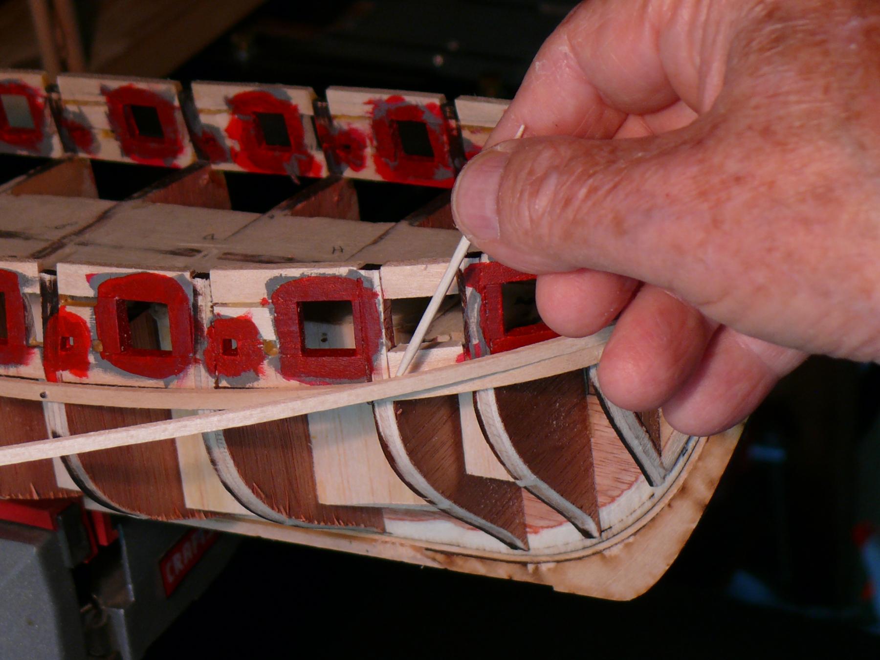
 For the other side I first cemented the strake to the bow to serve as an anchor.
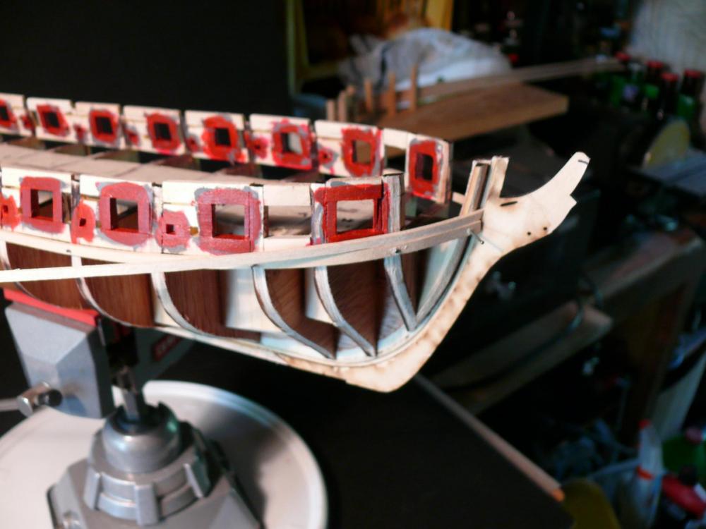 Then I put CA on a toothpick
 Applied the CA to the strake very conservative at the top of the strake.
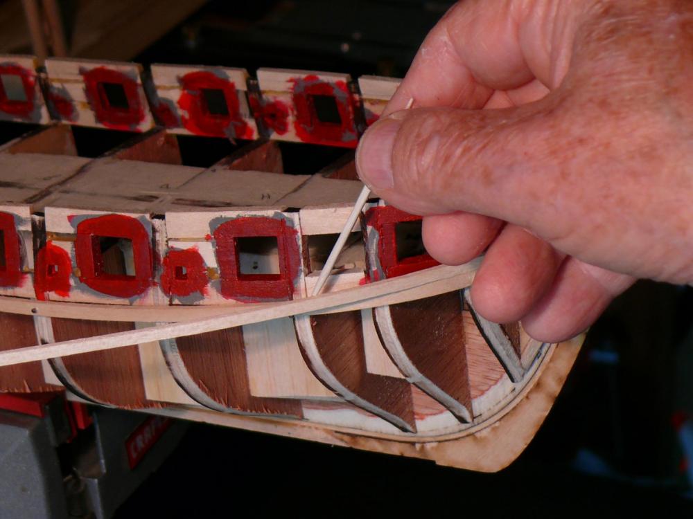
and glued it to the hull.

And so on for the rest of the hull.
Then I detached the wale, this time without problems. (Note. this is a deviation from the manual. Frankly, I don’t know if it makes sense. The intention is to be able to stain and finish the upper planking without interfering with the wales)
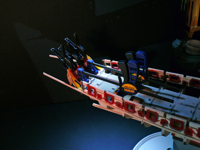
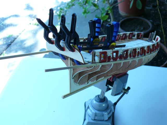
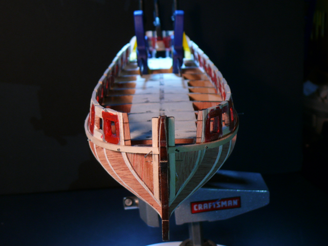
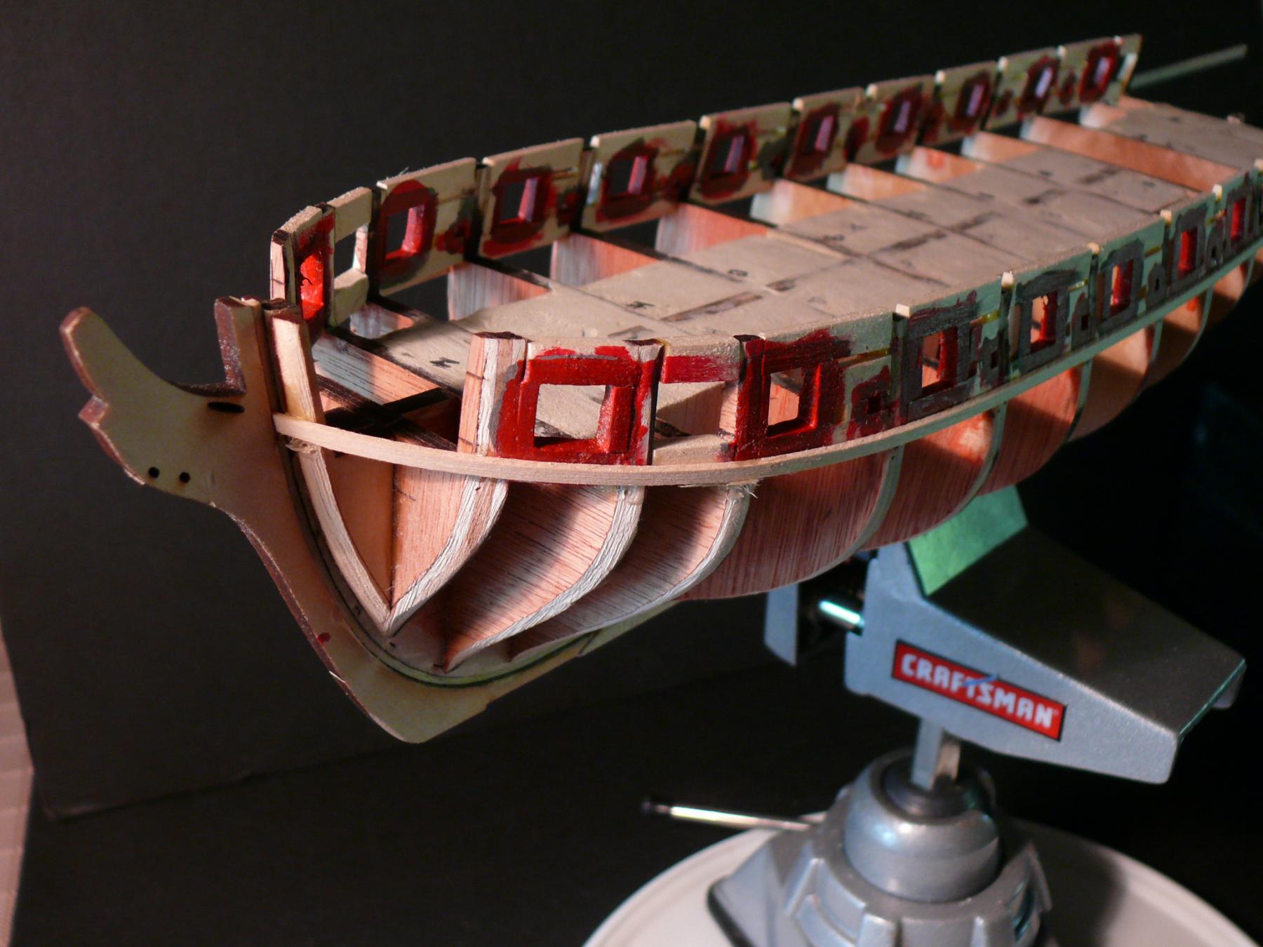
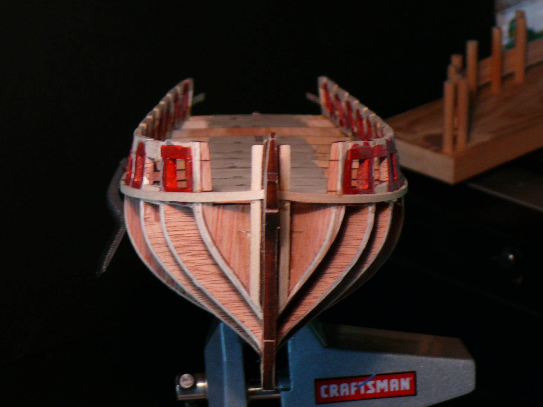
Here’s the first strake as viewed from the bow.

- EJ_L, Ryland Craze, GuntherMT and 1 other
-
4
-
-
EJ_L, GaryKap. Thanks for the advise. And thanks for your ongoing support. Donrobinson, I hear you.
In retrospect I would have heeded the advise. But now, after the bulkwark frames are done, it's too late for me to start shaping filler blocks. Partlicularly given my lack of skill in the shaping department. I think I have a better chance coercing planks.I did check other logs however, and am relieved to have company doing the planking minus filler blocks at the bow and stern. Actually the 'haves' are in the minorityHere's the rundown (yes means has filler):_SalD - yesGahm - noDubz - yesAugie - noJesseLee - yesMD11pilot - norafine - nortropp - noand the clincher: Chuck - no -
Thanks EJ_L. I'll take a look. Don't know if it is too late to put fillers at this stage. Also, why not let the planks acquire a natural curve on their own as opposed to having to conform to the shape of the filler? I'm not very good at shaping.
-
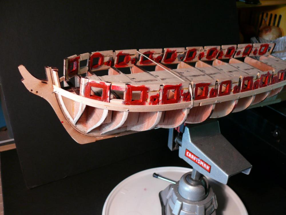
Chapter 5 - Planking
Positioning the first wale
The reference marks on the bulkheads have long since disappeared. So I have to find another way to position the first wale.
I’ll skip the preliminary step of placing a temp batten just to draw the reference marks, and work instead directly with the wale plank. The plan is as follows:
1) temporarily nail the wale plank to the hull (it’s OK to drill holes in it because it eventually will be covered by another plank to make the wale thicker).
2) glue the first 1/8 plank above the wale.
3) remove the wale, and complete the upper planking without it.
Repeat for both sides.
Postponing gluing the wale will allow staining the upper planking without affecting the wale. Later, the wale will be painted before installing.
One question remains: how to position the wale?
Looking at other logs, an in particular Sal’s (_SalD_), it seems to me the most important thing is to reach the correct sheer/profile of the hull. For that the position of the 7th plank is crucial.
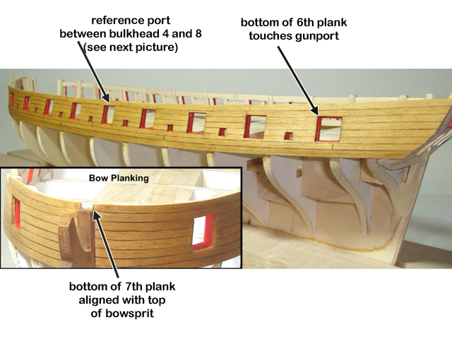
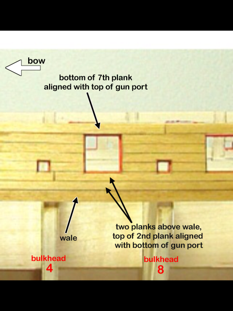
Looking at the instructions photos, it seems there are three places along the hull that must be touched in specific ways. These are shown in the following two pictures. If these positions are maintained, the rest of the wale in relation to each gun port can be eyeballed.
Here we go.
First the planking jig to shape all planks.
Preparing to build the jig.
The completed jig with pegs from a 5/16 (7.95mm) dowel. The pegs are long enough to bend multiple planks at once.
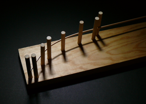
After reading Dubz frustration with the uneven size of planks, I made sure I had 14 planks of the same width. However I measured the width of about half the number of planks in the kit, and they all came up at 1/8. Possibly the kit has gotten better since Dirk time.
But then, I haven't yet taken a close look at the castings …
After selecting 14 planks, I cut a small piece from the end of each and used the pieces to make a measuring tool. The pieces are glued on paper to make the tool flexible.
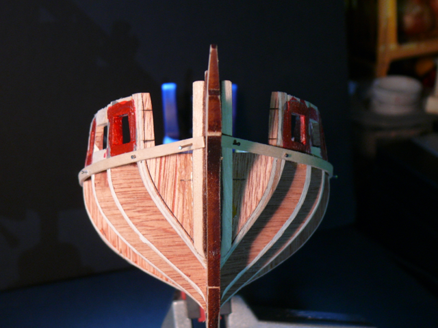
Here’s the little tool used at the bow to begin placing the wale.
First, the second gun port from the bow. I made sure there are two plank above the port, and one plank below the port.
 Then I made sure there is just one plank above the bow sprit,
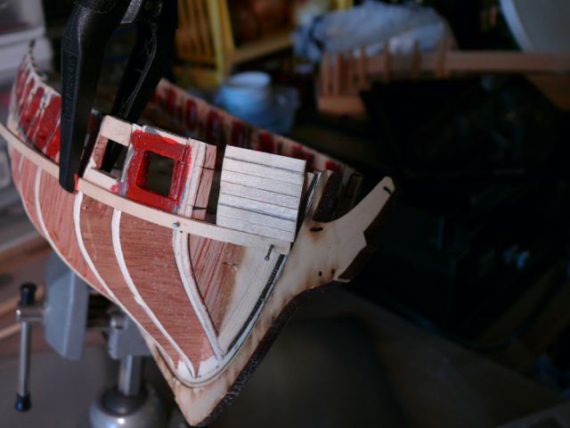 (notice the wale is not tucked into the rabbet at this point. Later it will be)Next I went to the stern and put one plank below the port and two above.
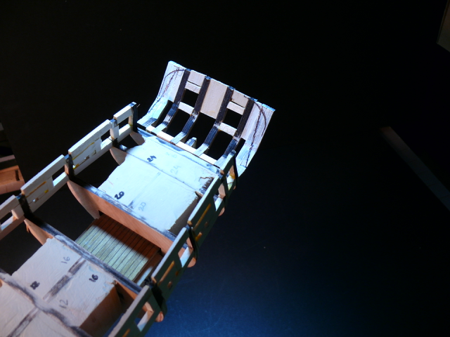
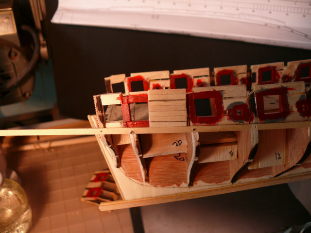 Then I went to the port between bulkheads 4 and 8 and ‘placed’ two planks below the port and one above, taking into consideration the rabbet around the port for the lid.
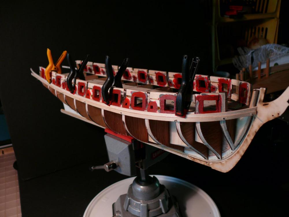
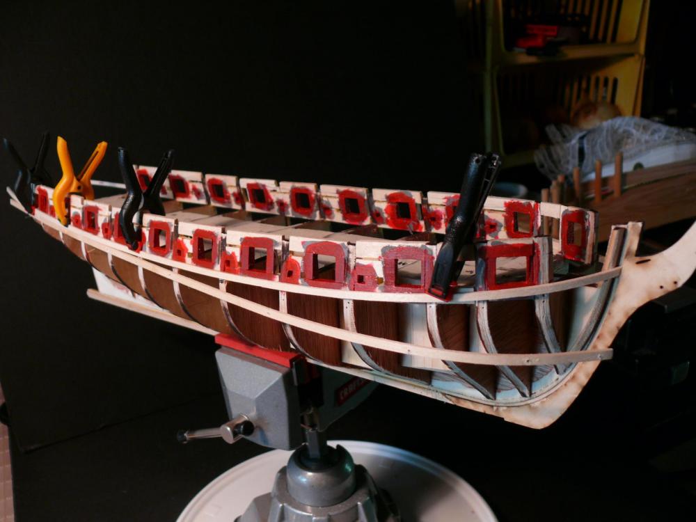
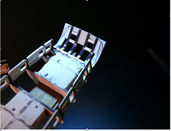
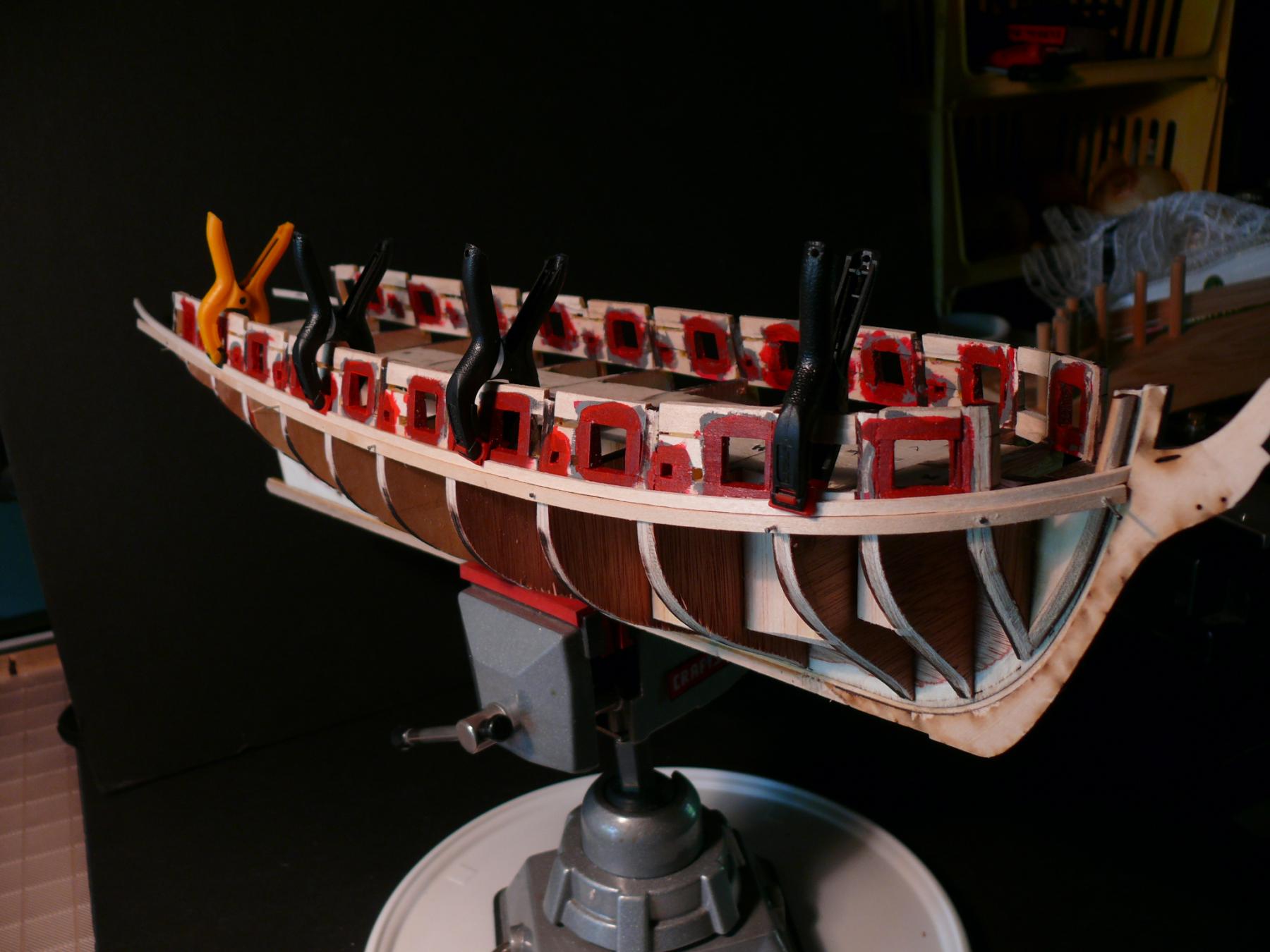
Here is a picture of progress so far. More adjustments were needed.
 Before continuing with the fotos, the second side was done like the first … or almost.For a final adjustments I put the model on a ‘Lazy Susan’ platform to quickly be able to look at both sides of the hull.
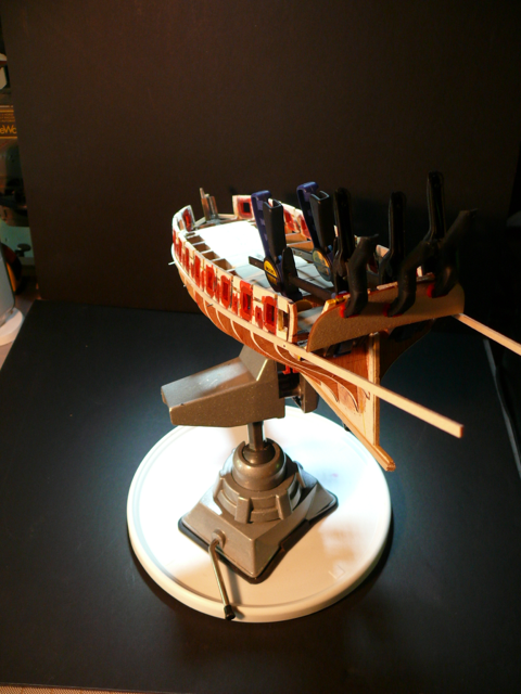 I temporarily attached the transom to the stern, and temporarily attached the stern to the ship.
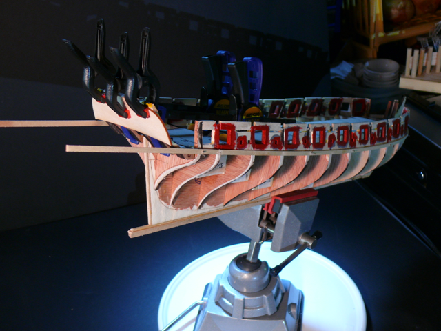
 Then I did more adjustments, but still not satisfied. Not all gunport are touched by the planks exactly the same on both sides … however for now that’s the way the cookie crumbles (like my British friend is fond of saying)
One thing must be the same on both sides: the distance from the top of the wale to the bottom of the transom.
Finally, here’s the view from the bow. (Looking at the photo, it appears the port side wale meets the bow sprit slightly higher than the starboard side. Unfortunately it is not an optical illusion, so more tweaks are needed).
The next step is to glue the first plank. Then I will remove the wale and set it aside until the upper planking is done.
———-
In case you’re wondering, I produce all photos with a Panasonic model DMC-FZ50 camera. It is very easy to use.
I take several shots of the same subject and choose the best. Most without a tripod.
All this takes time, and I think I spend more time with the camera and log than with the build. But I like both equally well, so no complaints.
And even though there is not a lot of feedback compared to other logs, the ‘likes’ are sufficient for me to keep on going. (Hint hint)
——-
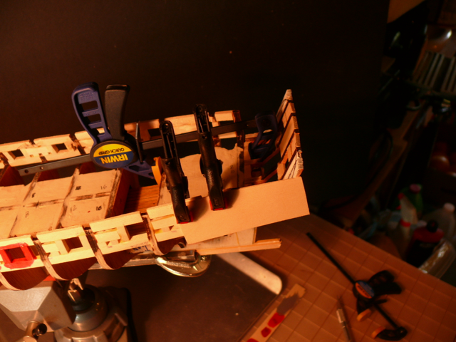
Finally in closing a confession: the apparent lack of clatter in the photos masks the reality of the shipyard. Here is a picture of it.
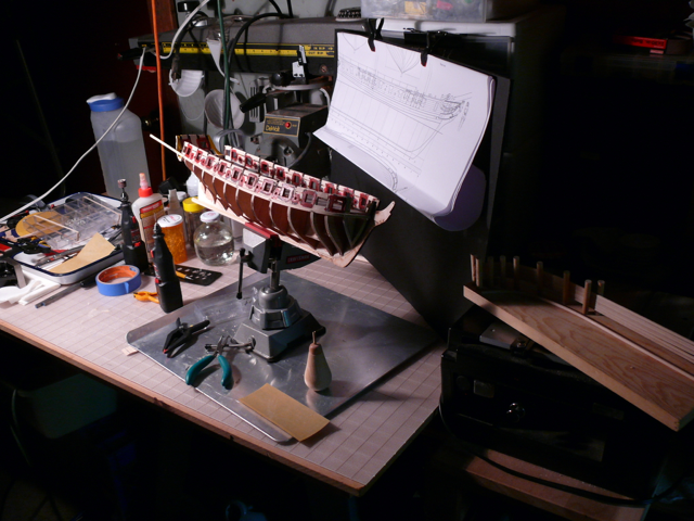
Thanks for reading.
- ca.shipwright, _SalD_, Dubz and 5 others
-
8
-
Shaping the Stern
Before planking can begin, the stern has to be shaped.
In my case, the stern is currently detached from the model. I am trying to keep it detached as long as I can because some tasks will be easier to do. For example shaping the transom.
I already marked the lines to trim the stern above the counter. But I don’t trust them.

So, let’s start again.
I fixed a 1/32 basswood piece to the side of the hull. This in lieu of using planks for the task.
Then I traced the profile of the stern timbers …
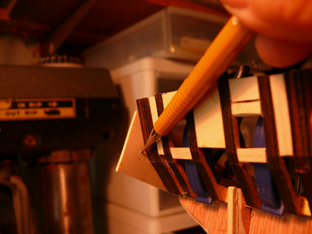
And ended up with two pieces like this:
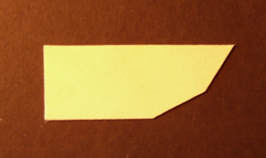
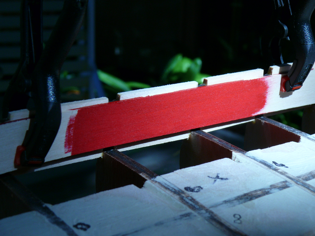
I erased the previous guide lines on the stern by painting yellow over them.
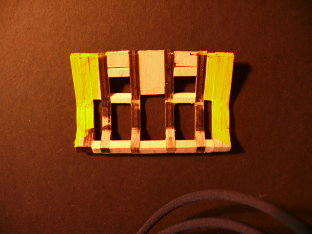
And positioned the two pieces from the previous step on TOP of the stern. I was pleased to see a tight fit.
 It was then just a matter of painting black the part of the stern that needs to be cut off.
 Here is the result for both sides:
 Now comes the scary part: how to do the cutting. One mistake and there goes the stern …
I tried the drum sander. No go.
I tried the power disk sander. No dice.
So I settled for the table saw. Scary scary!
I had to ensure I could glide the stern above the table without it changing position, and that I had the correct angle for the cut. The latter was the scariest part.
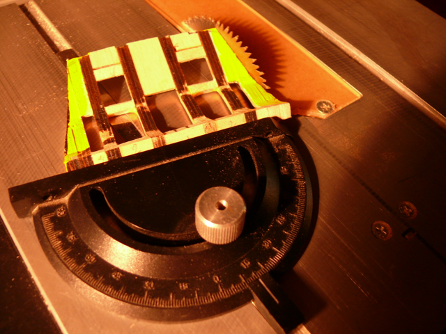
(I normally like to take pictures with the power tools functioning. But not this time!)

The stern is still detached, but here is a picture of it on the model.
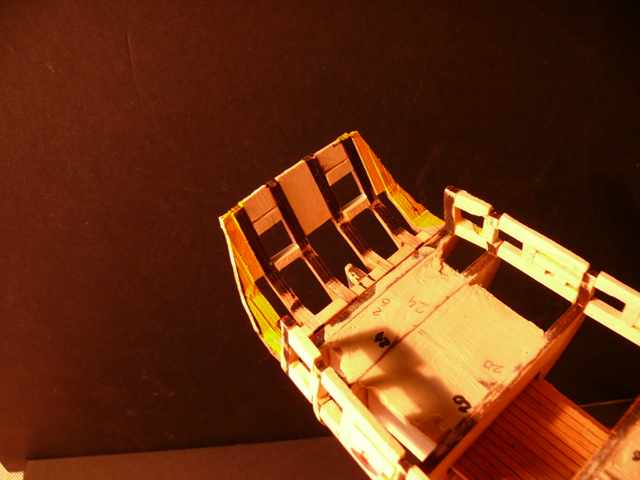 Because of the way the cut lines were produced, there is 1/32 wiggle room on either side for fine tuning later on.
Next, the beginning of planking. Finally!
-
A final note about colors
So, the Quinacridone Magenta makes the red too transparent. I should have thought of it sooner since I knew to stay away from anything preceded by ‘Quinacridone’ of ‘Naftol’.
In the ‘about paints’ forum section others too have observed the transparent nature of reds .
The solution is to use another less transparent color as a base before applying red. Not an acrylic primer, but another acrylic color of the same brand.
I chose Neutral grey:
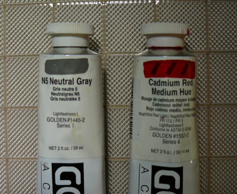
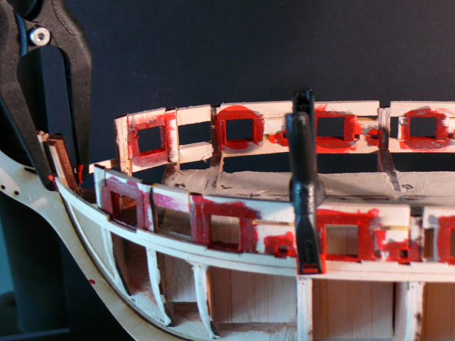
Take a look at the next test strips:
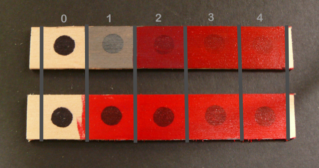
The top strip has gray as an underpaint, the bottom one just bare wood.
Each strip consists of successive paint layers. Pure Cadmium Red was chosen for the red. The reason for that is that with a gray underpaint the top red layer will appear darker, which is what I want.
The transparency of the red layers is obvious.
What I want is the #2 color of the top strip -- a dark red. And what that strip suggest is that I should mask the black dots entirely with gray before applying one layer of red. Just one layer.
That’s what I’ll do for all red color on the model..
But first, more about the stern.
- EJ_L, Ryland Craze and GuntherMT
-
3
-
E_JL, thanks. Couldn't say it better. I never paint the surfaces to be glued.
I'll have another post related to the paint used for the Syren shortly. Turns out the combination tested in my previous post is too transparent. All paints, acrylic or lacquer are. But the use of red and in particular quinacridone red makes it worse.I'll have another post on the final paint combination adopted shortly.When painting wood several coats are required. If prepainting, I'll only be applying the first coat, hoping it'll facilitate a clean delineation between painted and non-painted surfaces later on.Dubs has a good post on his method of painting (bottom of page 1 in Dubz log). And he recommends waiting until the handling of the hull subsides before finishing painting it. -
-
About Colors
My shipyard will be closed for a few days beginning tomorrow, so before closing I decided to experiment a bit with colors. Upon return I’ll paint the gun ports and sweeps, a preliminary step before planking.
Since I already have a full palette, I’m going to use my ‘Golden Acrylics' colors. These are available in any art store. (My previous models used lacquer colors, which are messier than acrylics).
I picked up three of my reds and tried different combinations.
- Cadmium Red Medium (not shown in photo below)
- Quinacridone Crimson
- Quinacridone Magenta
This picture above was taken with artificial light, which distort colors and makes them too bright. Compare them with a photo taken with natural (afternoon) light.
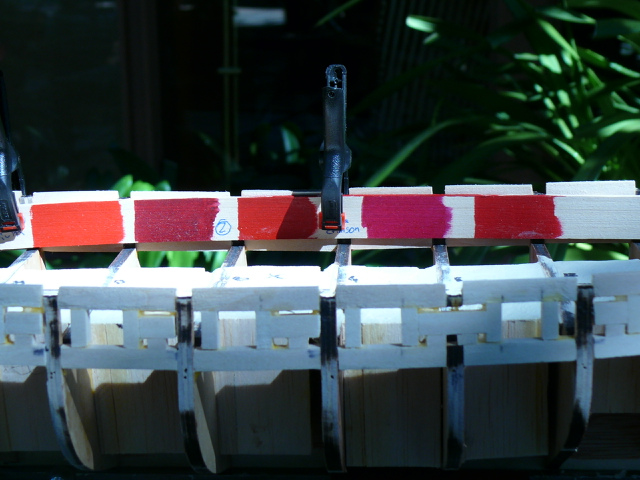
The swath on the far left is the pure Cadmium Red. Too bright.
The second is the pure Crimson. Too dark, wrong hue.
The third is a combination of (1) and (2)
The fourth is the pure magenta. Wrong hue.
The fifth looks right to me. I'll try that one: Quinacridone Magenta (80 %) + Cadmium Red (20%).
Here is what it looks with natural light:
 If you look at this sample, the left side is partially in the shadows and darker than the right side. This will be the hue of the displayed model which will be shown indoors.
Finally some comments:
The brush used is a super fine white sable brush. It is artificial, which is recommended for acrylics.
The above swath is the results of just one quick coat. It dried in a few minutes. In the model more than one coat will be used.
There are no brush marks.
The paint as it comes off the tube has a paste consistency. It has to be diluted with water.
The shininess of the paint can be controlled with Acrylic Matte Medium, which I didn’t use.
(Note. The Quinacridone red was eventually abandoned because of its transparency. See my next post)
Looking ahead, I may pre-paint and pre-stain all timber used on the inside and outside planking. Something to think about while the shipyard is closed.
- Ryland Craze, EJ_L and GaryKap
-
3
-
EJ_L, thank you for your ongoing support!
Ca.shipright, thank you for saying my approach to logging might be useful, and for observing that in modeling there's more than one way to skin a cat. We all have our ways, and I like to experiment. I hope my experimentation doesn't lead anyone astray. Because relative to the master shipbuilders you mention I rank at the junior birdman level.
- EJ_L and Ryland Craze
-
2
-
Chapter 4 - Stern framing
I did something different. I decided to assemble the stern off model. I thought it might be easier to assemble and that having a removable stern might be useful in some future tasks.
Time will tell.
So I gathered all the pieces ...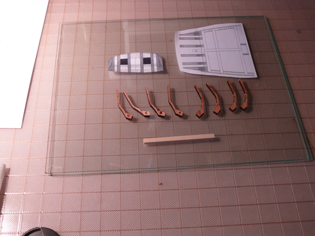
And proceeded to assemble the stern one frame at a time. There are 6 pre-cut frames.
Because the PVA glue does not bond well to glass, All gluing is done on a flat piece of glass.
first frame.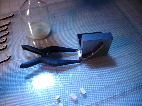
Second frame. It is important to keep the filler piece flat against the glass.
Third frame. The weight rests on the tweezer which in turn puts downward pressure on the filler pieces.
Fourth frame. Now I’m putting pressure of the end of the frames to maintain alignment.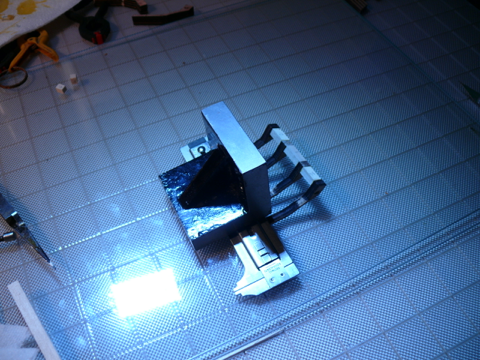
Fifth frame. (Two C frames glued together)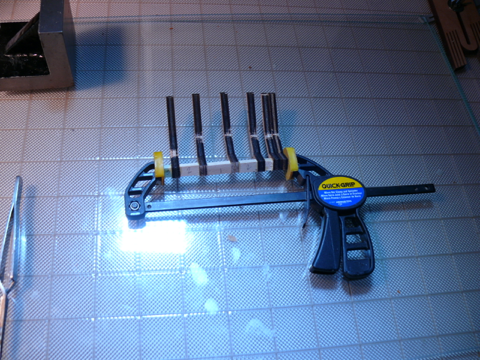
Last frame.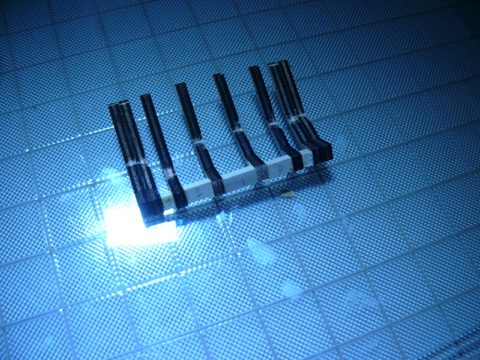
Checked the alignment … pretty good if I may so myself 
Temporarily placed the stern where it belongs …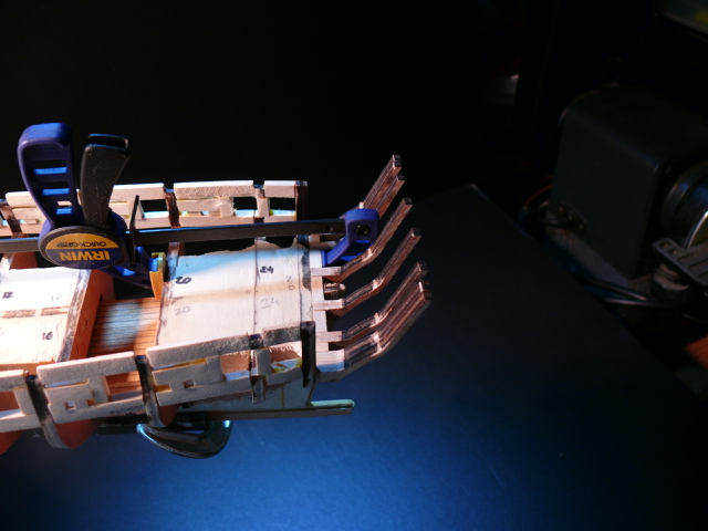
And checked the space between sills and lintels with a makeshift 2 pound cannon. Not very pretty but the height of the ‘barrel’ is accurate according to the plan.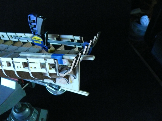
While I was at it, I attached a temporary batten to guide the placement of the sills.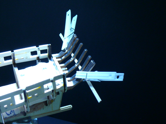
Removed the stern and proceeded to glue both the sills and lintels.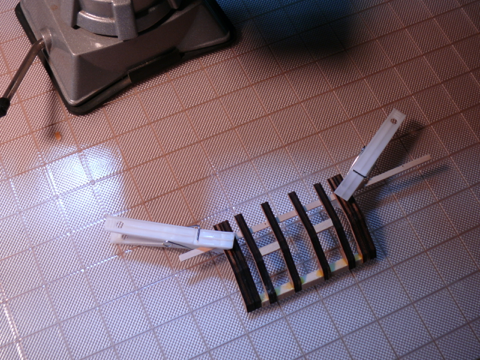
Re-attached the stern to the hull and marked the correct shape of the stern on each side of the hull (step 7 in the manual).
I posponed the actual sanding to the marked shape for later.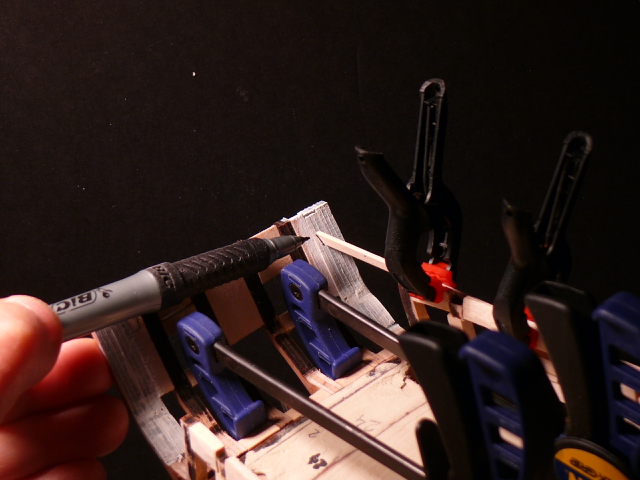
I turned the ship upside down and put two solid pieces below the counter (step 8). These two pieces have to be formed to the correct profile, a compound shape. This causes a bit of anxiety however nothing is glued yet, so no big deal if I blow a few pieces.
The two pieces where first cut with a scroll saw.
(The two pencil lines shown are from a previous mistake. To be ignored).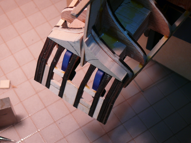
To shape the two pieces I used these tools.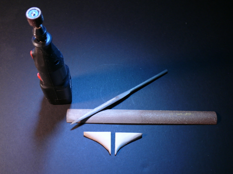
The end result, surprisingly on first try.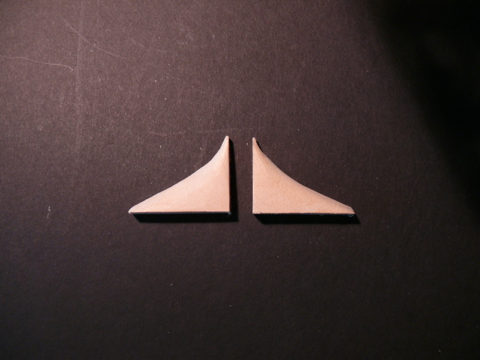
This is how they look on the model. Further shaping might be required depending on how the planking goes.
Once more detached the stern and set the pieces aside for the time being. If planking requires them to be glued I’ll do so later.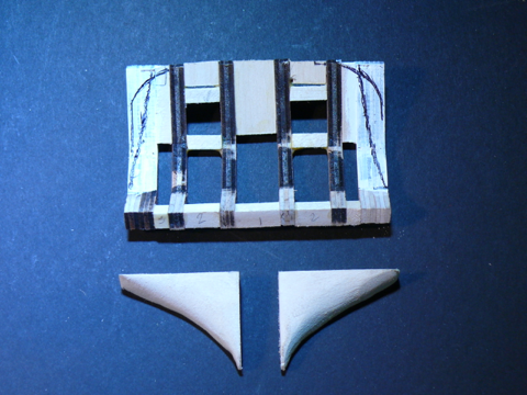
Next: planking.
But first a little digression.
I am aware there are better woods, but I’m going to build this ship using the kit’s original materials. (Except the cannons perhaps). I read numerous complaints about bass wood — too soft, hard to cut sharp edges, etc. — but I actually enjoy working with it, and it has the added advantage of being cheap and of being readily available in a number of hardware stores in my area.
If I follow my custom, it is likely this is my first Syren, a learning one that will be followed by another. (Assuming I’ll manage to finish this one )And the likelihood of my building a second Syren explains the profusion of pictures in this log for seemingly simple tasks (for which I apologize). I might be one who checks the log on my next time around.
Thanks for reading.
-
Rob the SWO, Thank you for your kind words! Comments such as yours keeps us going.
I was reflecting on what personal attributes contribute towards completing a model, it being a beginner model or an advanced one. I think number one is love of the craft, then an unshakable ‘can do attitude’, perseverance and patience (I’m still working on this last one). Skill contributes to the end result, but it’s not what gets a model completed.
I know attempting an advanced models such as the Syren as the first model is not recommended. Yet some have done exactly that and completed the model.
Attitude, perseverance and patience.
Like the ancient Chinese proverb says: “The longest journey starts with one small step”.
…/hervie


US Brig Syren by hervie - Model Shipways - Scale 1:64
in - Kit build logs for subjects built from 1801 - 1850
Posted
The third plank
The third plank is a potential project killer for me. Here is where the rabbet around the gun ports has to be cut by hand.
First, after pre painting with just one coat, I attached the first plank on the port side and did the faux plank butts. Just a shallow cut every four bulkheads.
(Incidentally, I chose the Benjamin Moore acrylic house paint. They work great!)
Then I attached the second pre-notched plank, as described in a previous post.
I simply can’t.
So I experimented with Dirk’s (DubZ) method of cutting using a chisel. And it all went well ... for a while…
I assembled the tools for this task …
And tried my real life first cut.
Success!
But then DISASTER!
When cutting another gun port, the entire port frame, lintels and all, decided to part company with the ship.
I was so shell shocked that I forgot to take a picture. It wasn’t pretty!
So I decided to do each plank in pieces between gun ports.
Here is the beginning.
(Although the pieces are short, the plank needs be pre-bent to follow the contour of the hull. Each successive piece is then cut from the same plank beginning at the bow).