


jep1210
-
Posts
37 -
Joined
-
Last visited
Content Type
Profiles
Forums
Gallery
Events
Posts posted by jep1210
-
-
-
Great update, coming along nicely.
-
Wait, there's a micro switch on the accelerator pedal? 😲 That means push pedal get engine sounds???? 😍
- mtaylor, popeye the sailor, Egilman and 2 others
-
 5
5
-
Climbing on board for this one, dis gunn be good. My vote is -1 scheme (green tail) wings extended.
- lmagna, Canute, Landlubber Mike and 6 others
-
9
-
This looks great.
- Canute, Edwardkenway, Egilman and 2 others
-
5
-
This is awesome.
- Old Collingwood, Canute, Egilman and 2 others
-
5
-
-
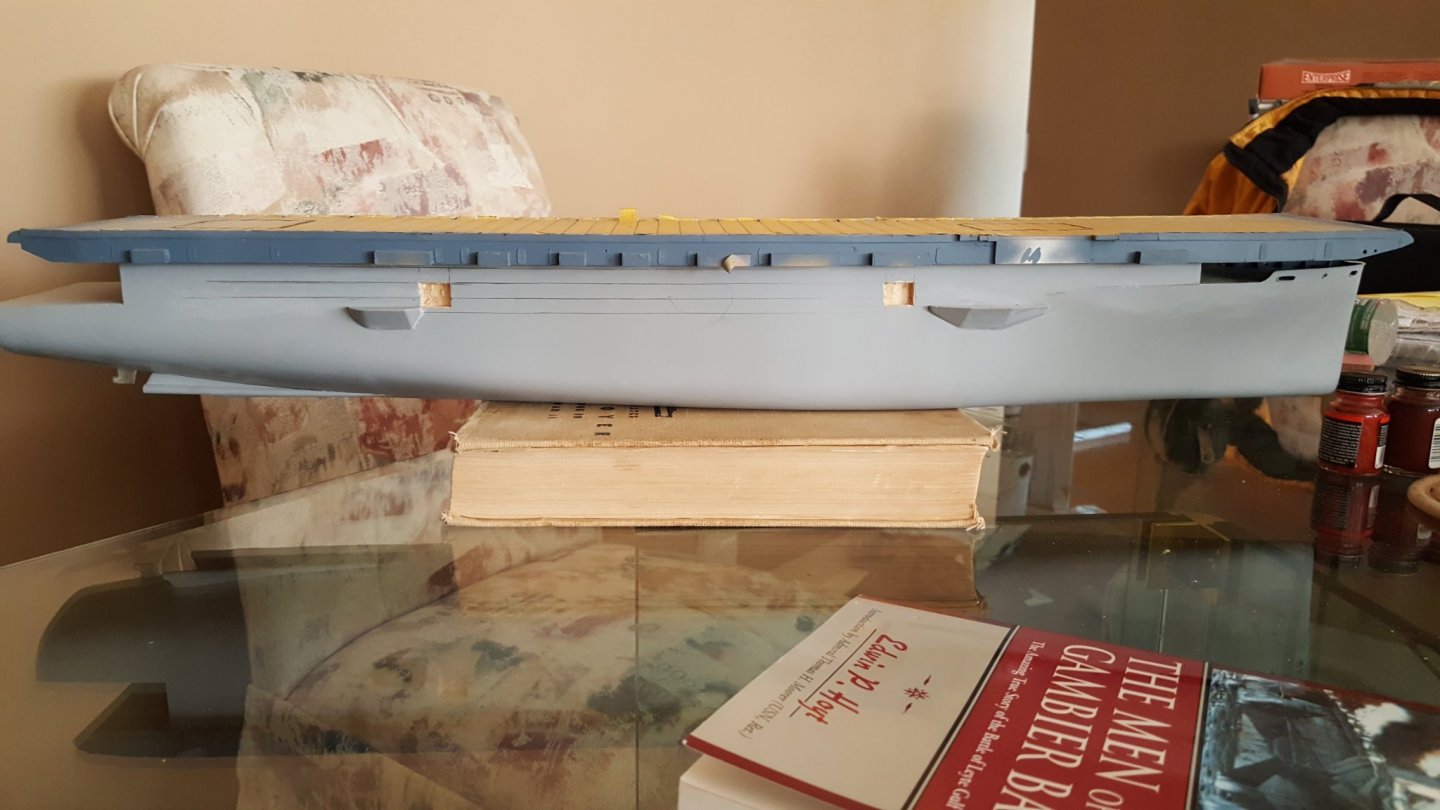
Thanks Schooner, thats good advice. It's much more evident in the recesses for the cargo doors on the starboard side than the sponson itself, and the bottom of the recess is level with the top of the sponson so it stands to reason the sponson is off too. As you suggested, I'll have to verify the area the flight deck sits on, I've been using that to measure from, and make sure the ship sits level on it's keel. We have height gauge at work that I'm going to grab to do some measurements off my glass top table not that book, I would assume it won't sit more level than on a glass table top . 😉
John
-
-
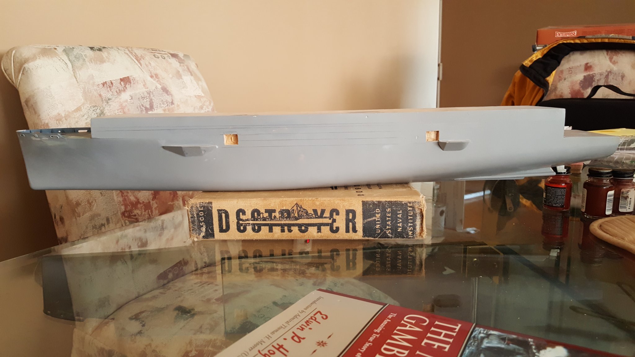
Hi 'yall,
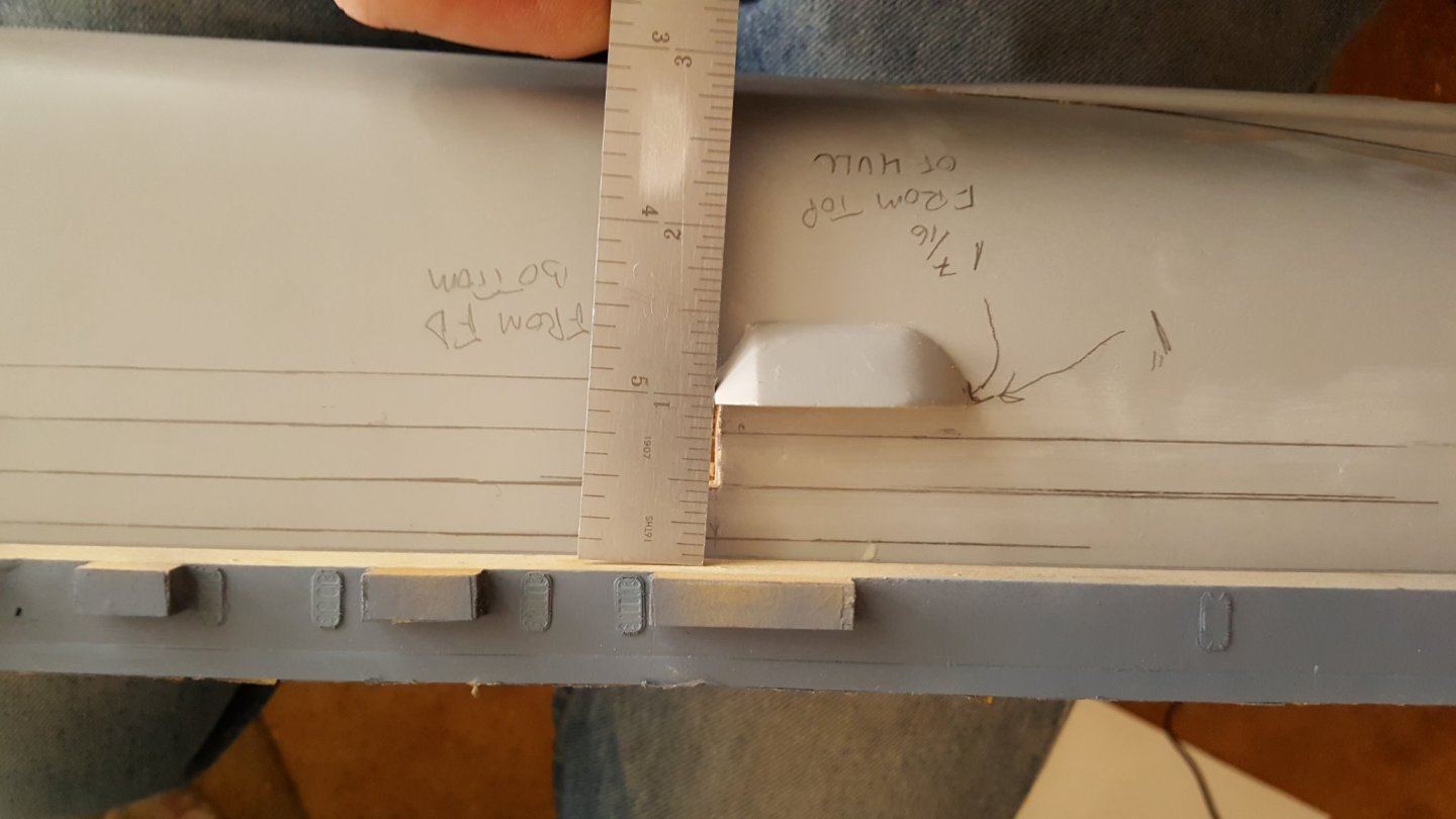
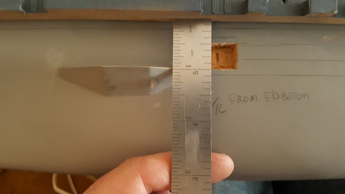
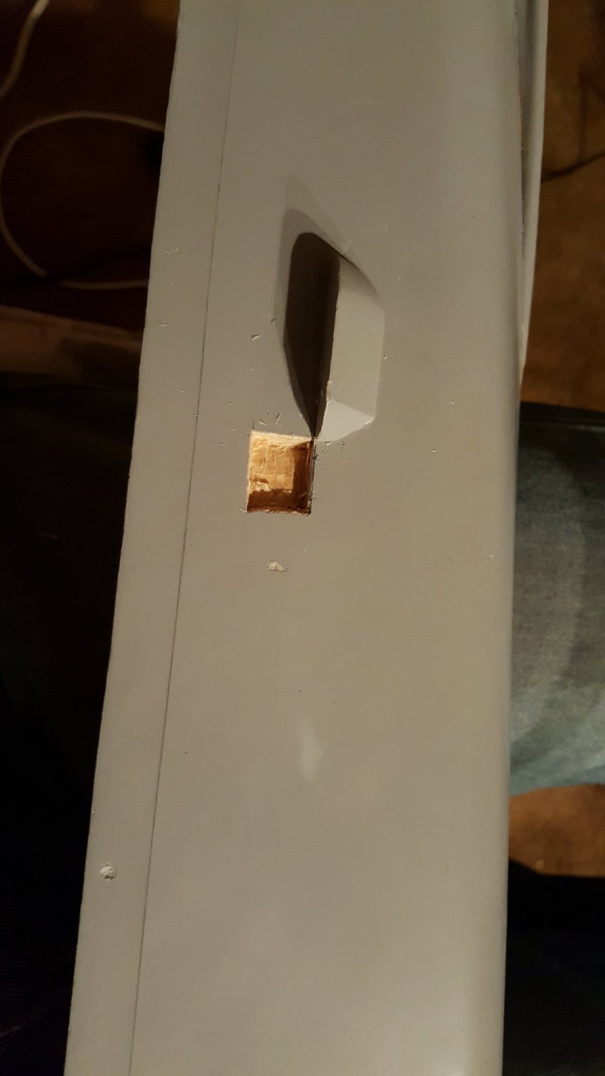
So I hit a snag right out of the gate reopening. 😁 I cut in recess for the cargo doors that go into the hangar deck last night and while sitting starring at it while having breakfast this morning, I noticed they don't look level. 😡 It wouldn't be so bad to fix but it means the sponsons are also not level with each other. However when I measure them, there's only a 32nd-16th of an inch difference. How can 16th look so off? Not sure what I'm missing. Also, they are both about a 1/4" too high according to the plans I have but I can live with that as long as they're even.
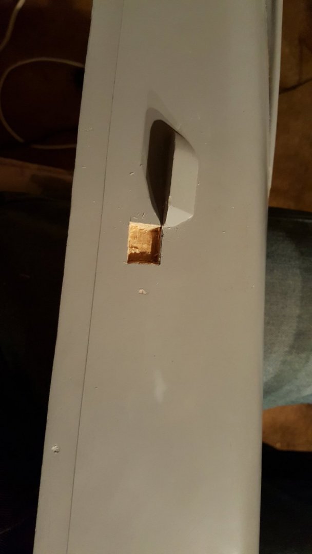
My plan is to make a 5/8 by 1/2 inch box out of .250 styrene to "box in" the opening sort of shadow box style.

Port side
Starboard side

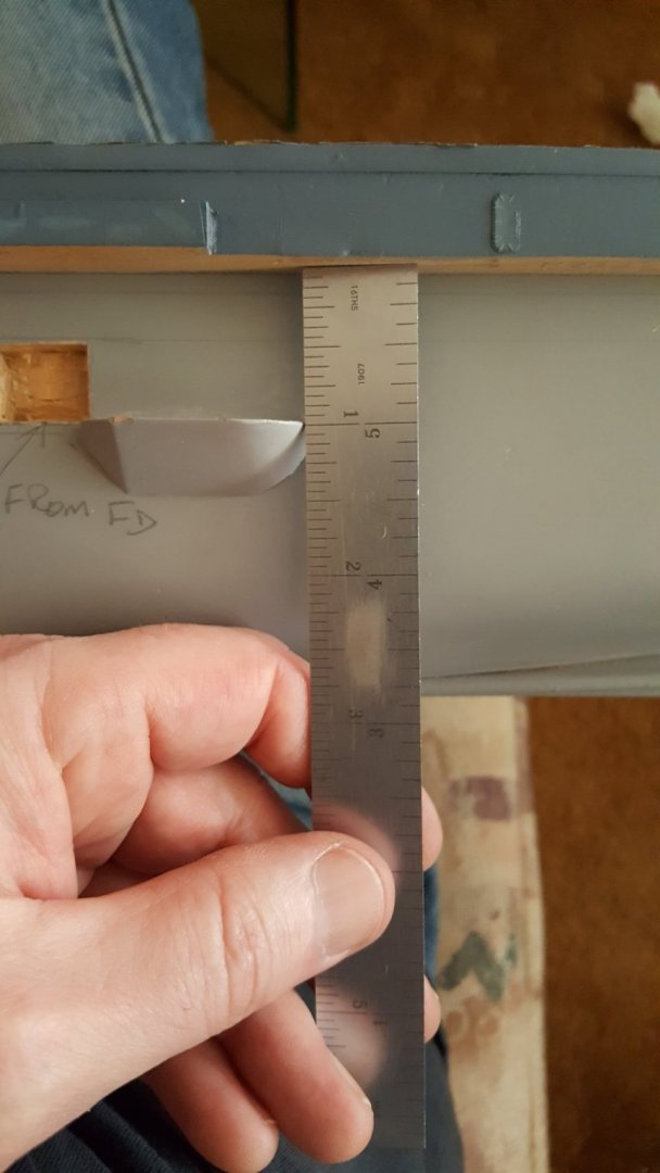
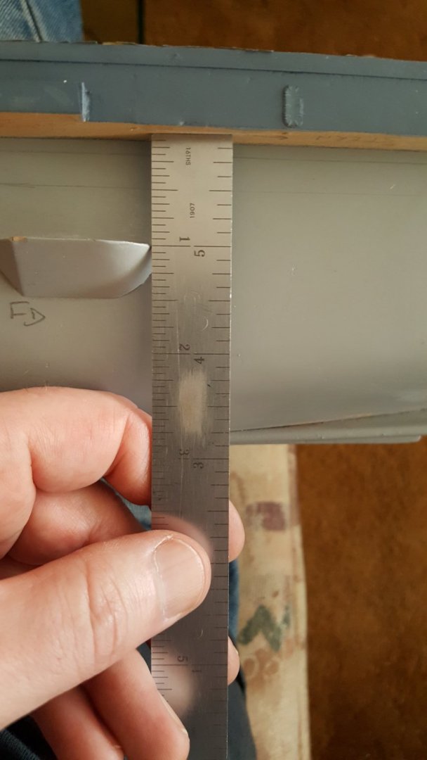
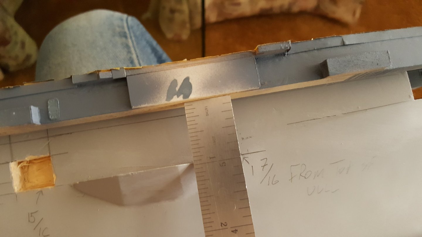
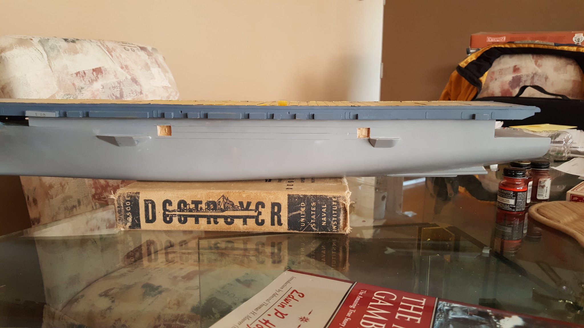
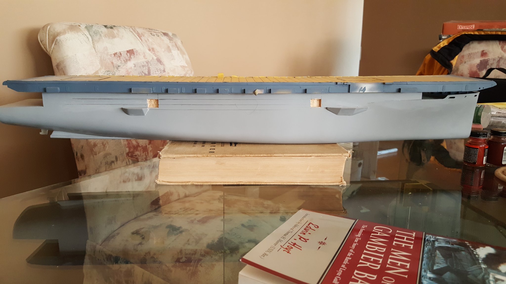
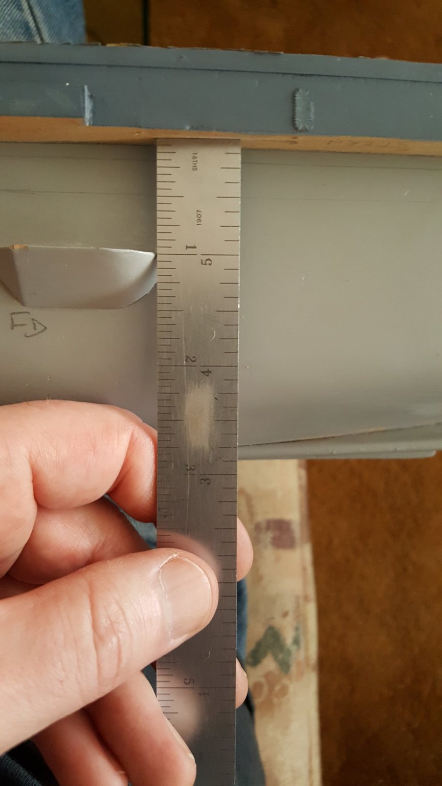
It's really evident on this port side shot with the flight deck removed, but when I measure it from the top of the hull, both sponsons measures the same distance or at the very least, with in a 32nd".
Starboard aft sponson.
Starboard Aft sponson...not sure why this one pic is upside down, sorry I can't get it to flip.
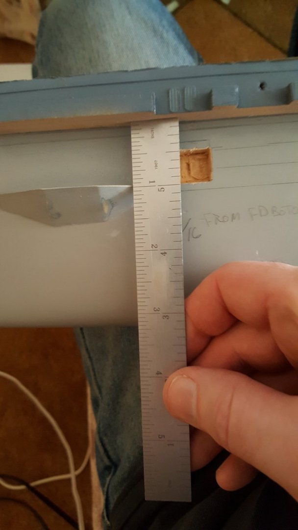
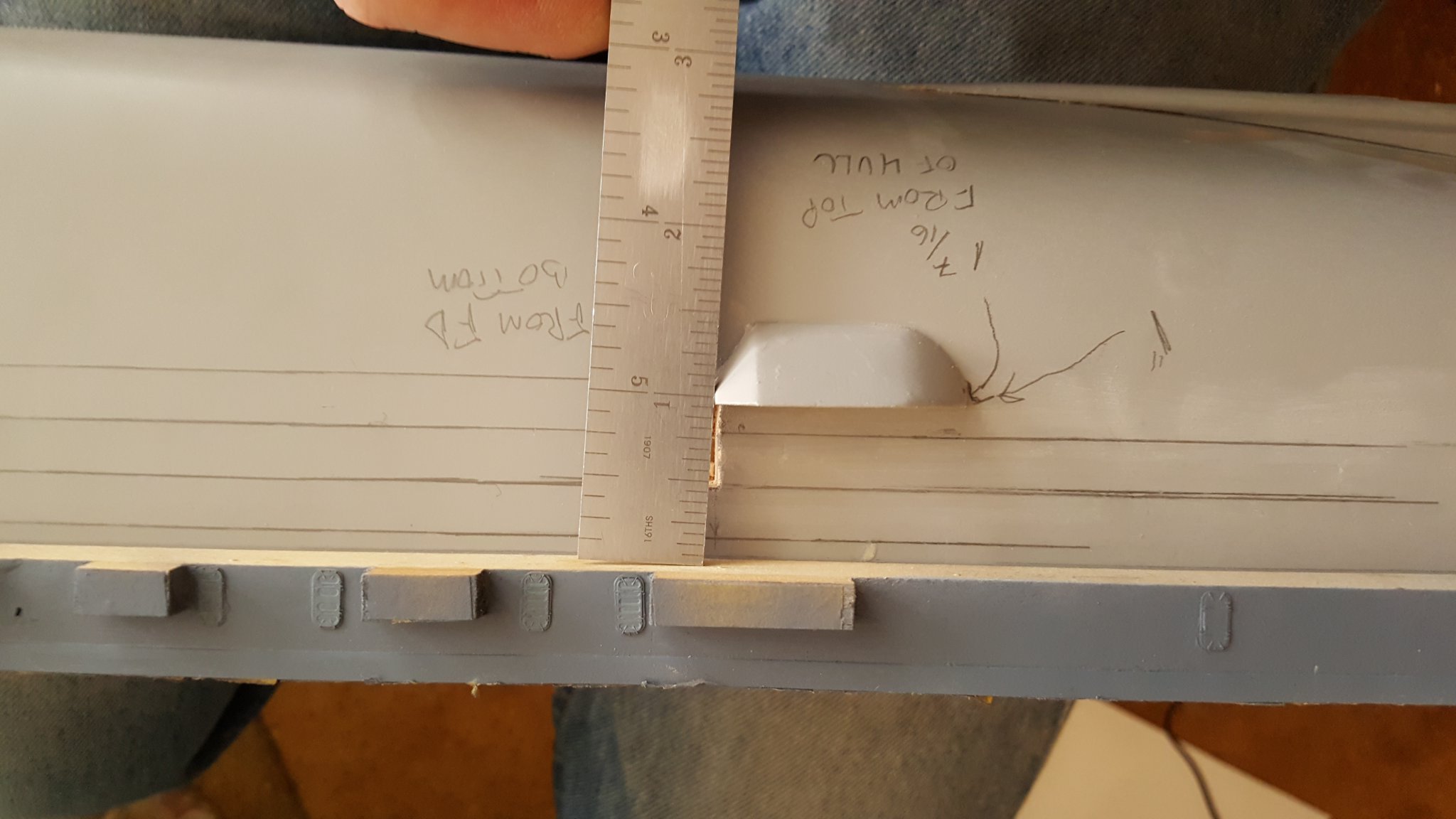
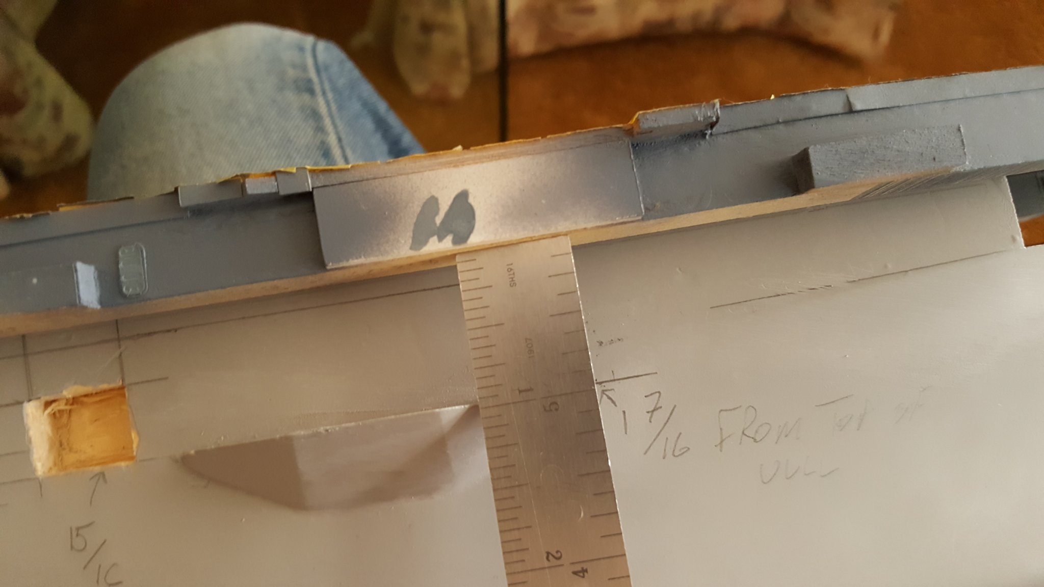
Port side fore sponson. This one actually "noses down" but I can fix that (i.e. hide) with a skim of putty once the deck has been installed, this sponson is slightly undersized anyway.
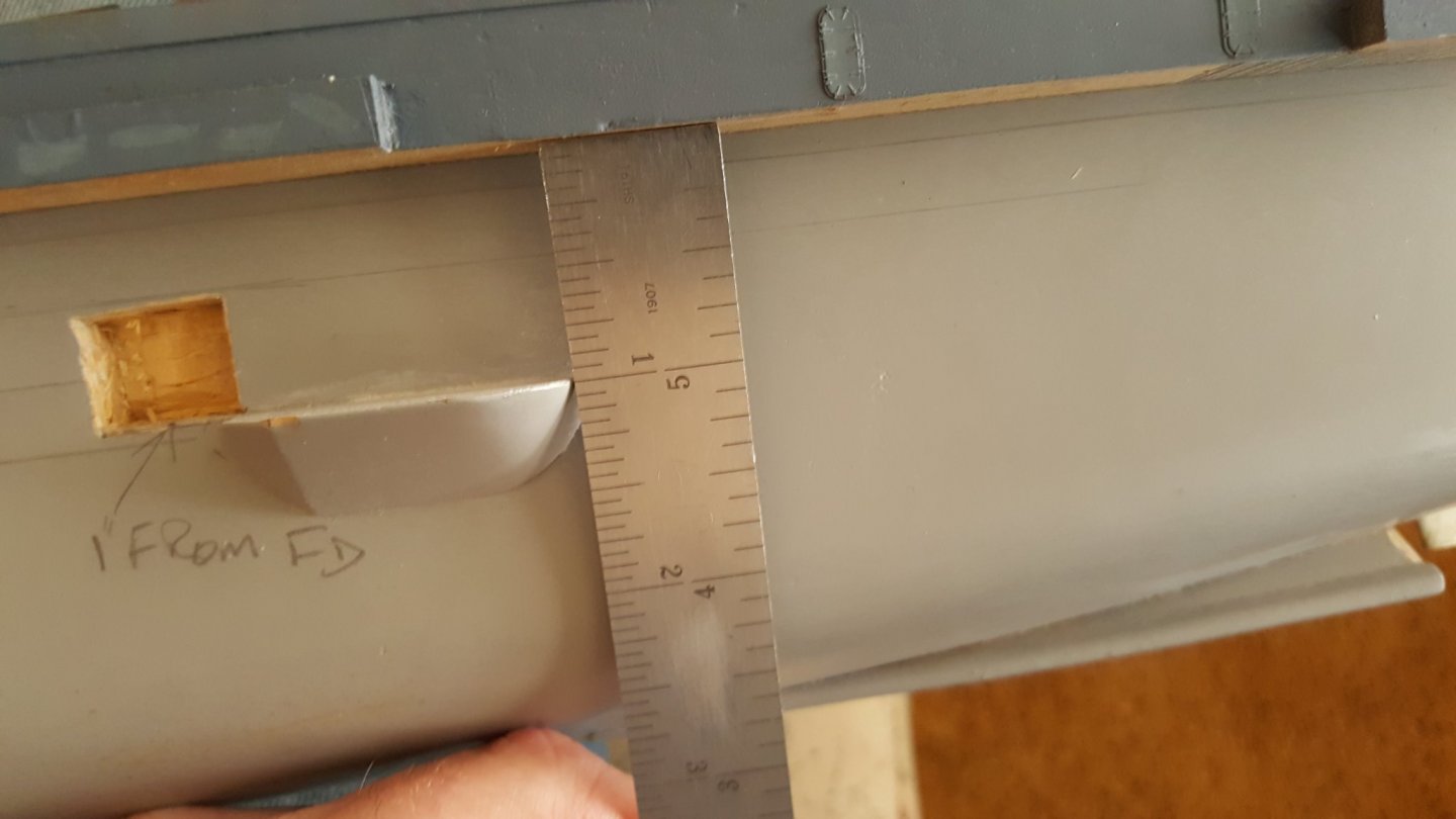
Starboard fore sponson
All measurements seem to be fairly even but for some reason it looks off. I really don't want to remove those sponsons as it would mean making new one....these came out really good if I do say so myself...but I'm thinking there isn't any other option other than to remove at least one of them and reposition it.
Any suggestions would be greatly appreciated.
John
-
-
Whoo, got all caught up in this build, coming along nicely. Still a little unclear of your plan for it, R/C, static, I think you said static and I assume you're getting the extra running gear to make it more accurate with 3 screws???
- Canute, popeye the sailor, lmagna and 3 others
-
6
-
Oh man, this looks like it gunn be good. I'll have to catch up on this and Mog's build when I get home from work....tsk stupid work...always getting in the way of fun...they want me to be productive, I show up isn't THAT enough?!?!?!

- Old Collingwood, Canute, lmagna and 3 others
-
6
-
Yikes, I just stumbled on this post. Such attention to detail, amazing. Can't wait to get caught up on this build....only on page 2 so far.
-
19 hours ago, Egilman said:
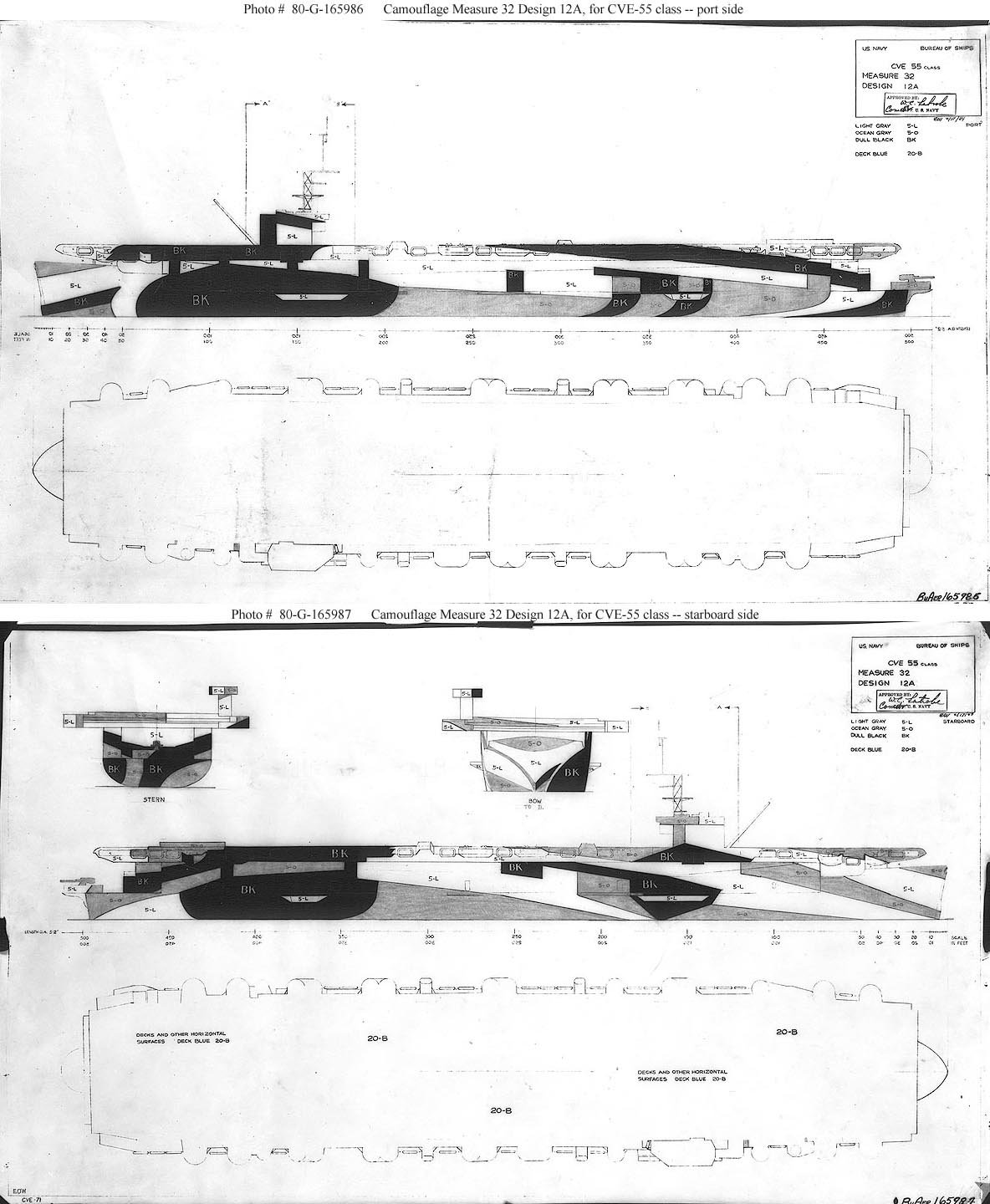
Measure 32/12A...

Measure 32/4A....
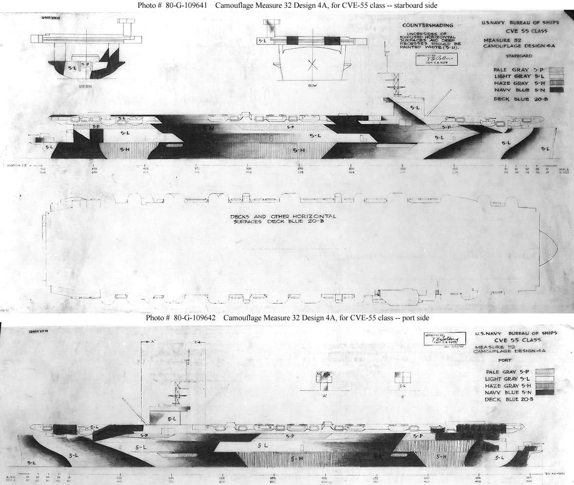
Check your pic references for when what ship had what pattern.....
Given the wide fades between 5-L & 5-H to the 5-N bands on pattern 4A, 12A would be the easier pattern to paint IMHO.....
I plan on using an airbrush so I don't think the fades of 4a won't be too difficult.
-
19 hours ago, Dr PR said:
Navsoource has a lot of photos of CVEs, some showing details.
https://www.navsource.org/archives/03idx.htm
Thanks for the link, there's some great shots there. I'll have to comb through those many many photos to see if they cover any details I'm missing.
- Landlubber Mike, mtaylor, lmagna and 2 others
-
5
-
20 hours ago, Landlubber Mike said:
I have the Anatomy of the Ship book, and didn't see any pictures of what I think you are asking. Have you looked here at these reviews of the kit and PE sets? They have the instructions copied there so they might be of some help? I unfortunately couldn't locate a similar review for the "Super Detail" set.
http://www.modelwarships.com/reviews/ships/cv/cve-73/350-hsg/hsg-review.html
http://www.modelwarships.com/reviews/pe/hasegawa/350-cve73basic/hsg-review.html
http://www.modelwarships.com/reviews/misc/hasegawa/350-deckcve/hsg-review.html
http://www.modelwarships.com/reviews/misc/hasegawa/350-usn-ac/hsg-review.html
Thank for the links, they don't really show the area I need but do show a lot of other details. I have the Anatomy Of The Ship book too and there's no pictures or plan drawings of the area in question however, I did find an incredible 1/72 scale Gambier Bay build on Model Warships by a gentleman named Bill Waldorf. In the picture below I circled the area I'm talking about in red. Not sure if Bill took some artistic license or if what he did is accurate...either way, it works for me.

Here's the link for anyone who's interested, hopefully it's alright to post a link to another site ModelWarships.com Review
-
I've never heard of this company. These kits look awesome....off to Google.
- Old Collingwood, Egilman, James H and 3 others
-
6
-
1 hour ago, Landlubber Mike said:
Glad to see you're dusting this one off. Nice progress! I recently picked up the Hasegawa kit and am surprised to not see more models of these pretty cool escort carriers around.
Thanks Mike, I'm surprised there aren't more builds too. I found one build of the Hasegawa kit on this site by Alex Parker, but that one hasn't been updated since last October. Can't wait to see your progress. If you happen to get a chance could you take some pics of underside of the Gallery deck...I think that's what they call the area with the 20mm and 40mm guns? I need a reference on what the girder layout is on the underside of that area.
- Landlubber Mike, Egilman, lmagna and 2 others
-
5
-
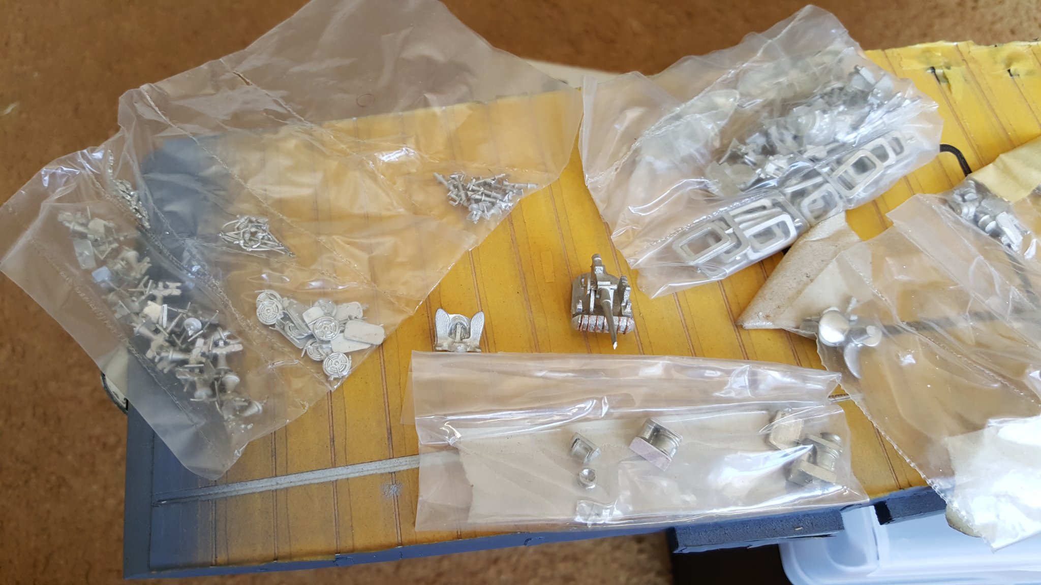
I took a few more pictures but sorry, none of them are any further progress shots, just kit contents.

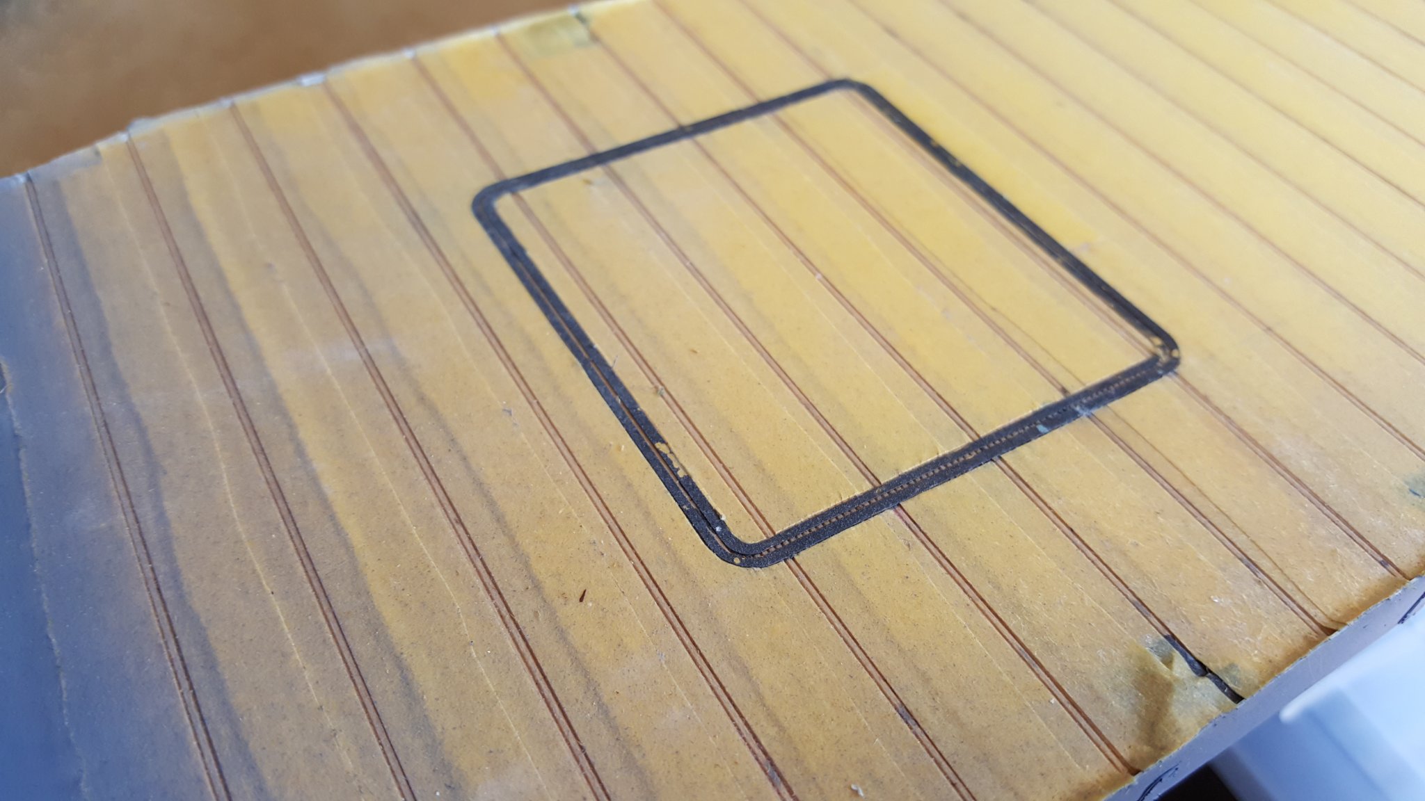
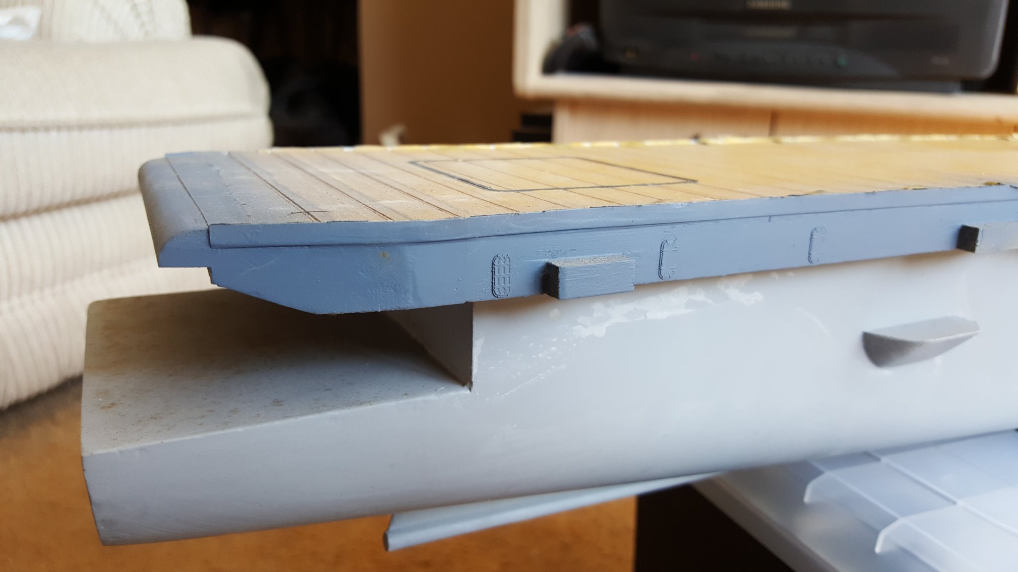
Still not sure if I want to try get the photo etch elevator outlines to sit more flush...not even really sure how I'd achieve that having already glued them down.

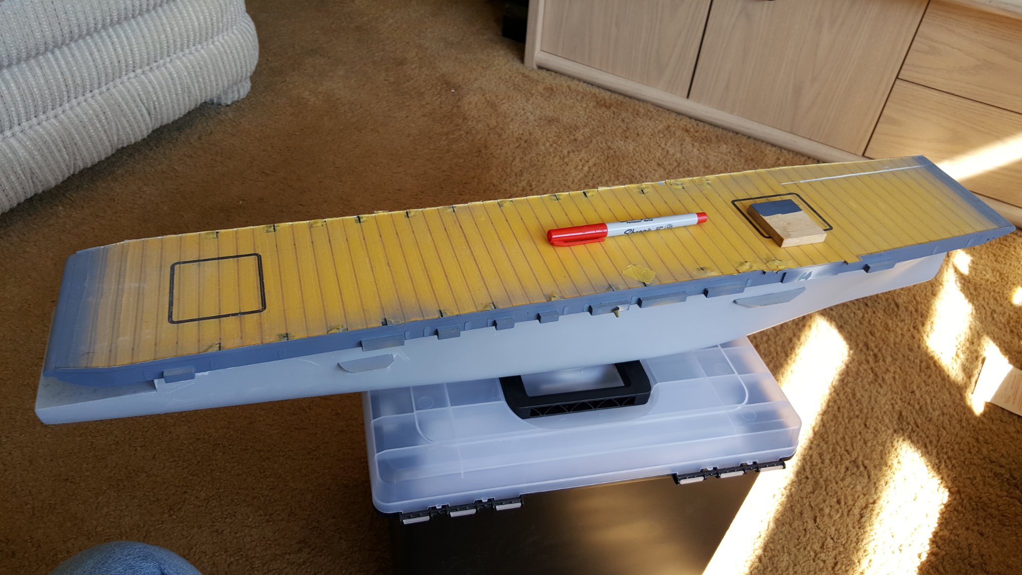
The wood block is what will become the island, not in place obviously. I included a fine line Sharpie for an idea of scale. I'm toying with the idea making the island out of sheet styrene.
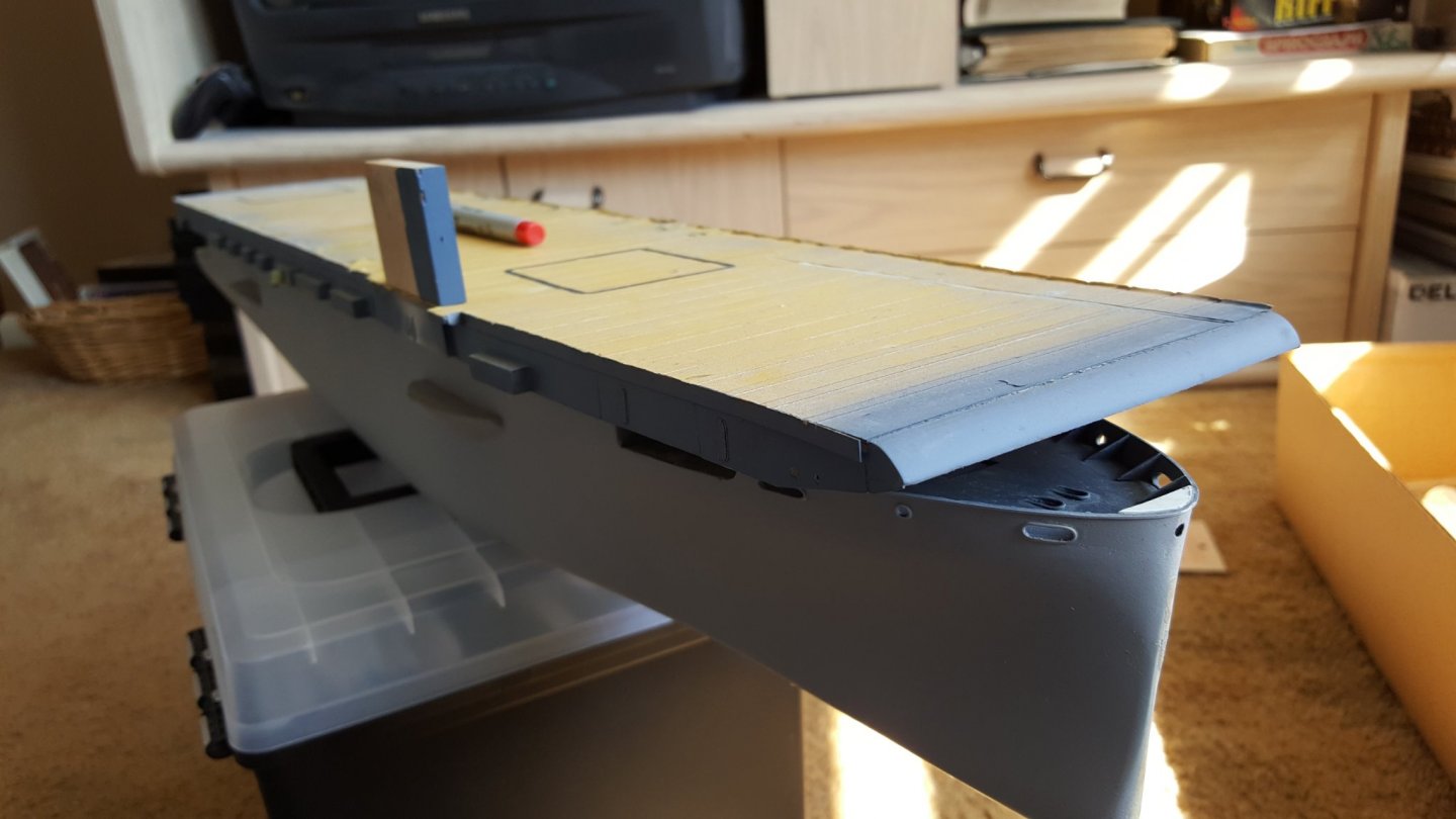
The "Island" in the approximate final location, it'll be lower and more on the side of the flight deck.

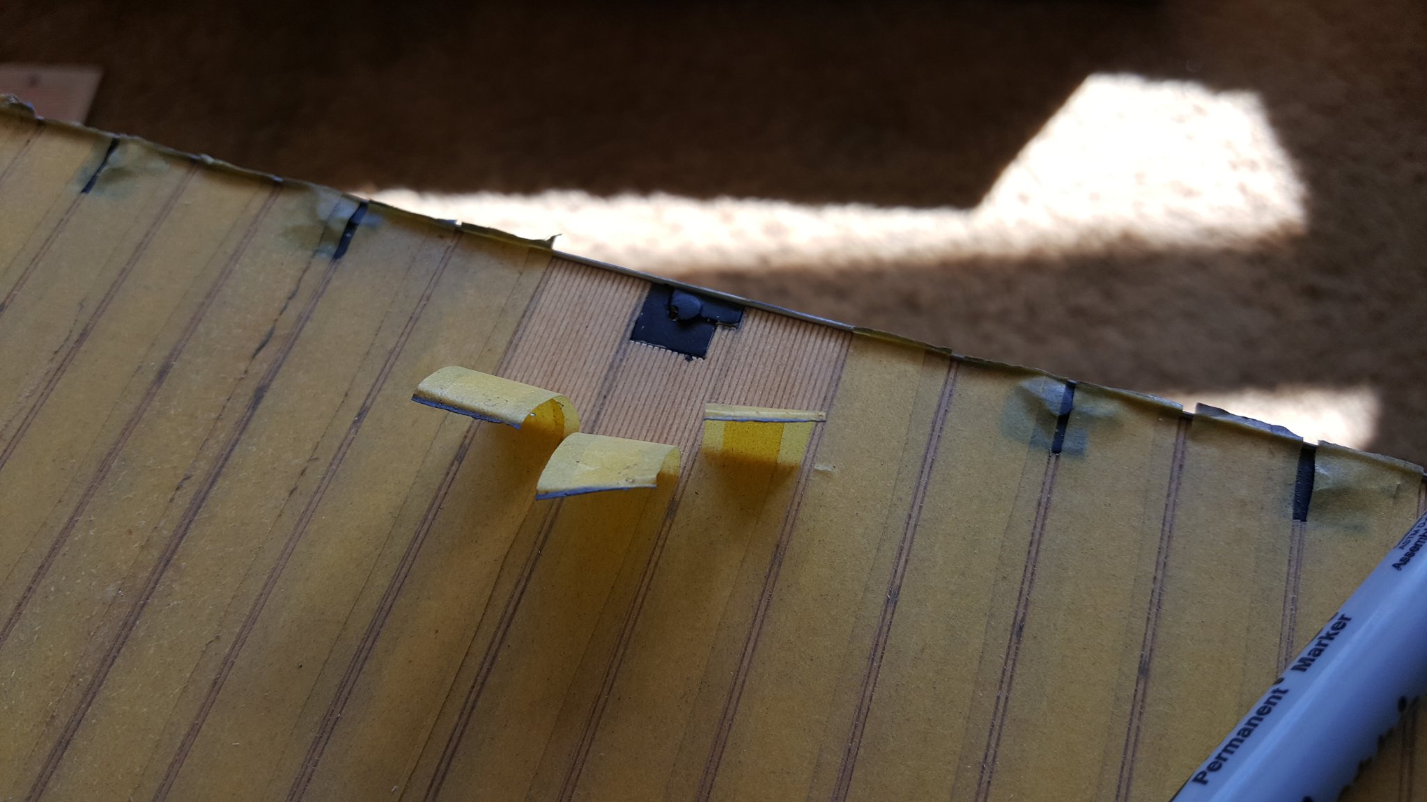
I peeled back some of the tape, gives you a look at the decking and one of the many plates where the arrestor wires come out. These were easy to get to sit flush unlike the elevator outlines....can you tell those elevators are a source of frustration? 😄
 Fittings....
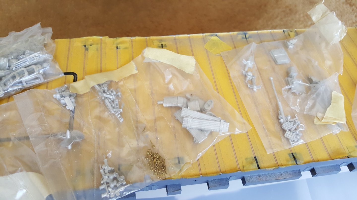 ...fittings....

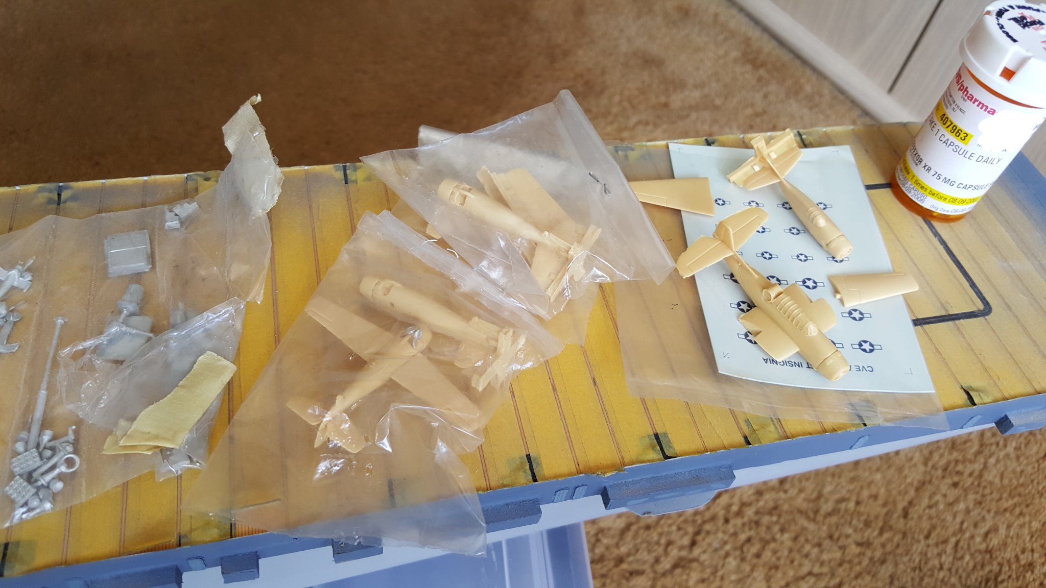
...and more fittings + planes. The kit only gives you 6 planes, 3 Wildcats and 3 Avengers but I bought 3 more of each when they were available. I would have gotten more but I remember them being fairly pricey.

Here you can see some of the different styles of doors that come in the Tom's Modelworks set. I tried to keep as many of the same types together so it wasn't as noticeable. The little blocks of wood between the doors are supports for decks that are yet to be installed. On the Casablanca CVEs, there was two levels of decks that ran along the side of the flight deck with stairs that ran down to the doors, if that makes sense. At this location between the two blocks is where the port aft 40mm gun tubs will be, there is no middle deck where the 40mm gun tubs were obviously.
My original plan was to go with Gambier Bay's original MS-21 paint scheme, which was Navy Blue 5-N overall, hence why I started painting some areas with that color. I just felt MS-32/15a, the scheme she wore when sunk, the scheme you see in every image of CVE-73, was WAY more complicated than I wanted to attempt. But I recently discovered Measure 32/4a which was carried by CVE-60 USS Guadalcanal, which has a remarkable story in her own right being the only US Naval ship to capture an enemy vessel on since 1815(according to Wikipedia), German sub U-505. Seems a little more manageable to achieve even though CVE-73 probably didn't wear it.
Well thanks for looking hopefully some of this is interesting to someone. I'm really fired up to get this project going again...I just have to figure out were I left off and where to go from here....oh yeah, and what to do about those damn elevator out lines. 🙂
John
- GrandpaPhil, lmagna, etubino and 4 others
-
7
-
-
19 hours ago, Harvey Golden said:
Looks great. Original was built just up the road from me. Git 'er finished by Nov. 22, and you can have an anniversary launching!
LOL, That's awesome, but it may have to be it's 90th or 100th at the pace I'm going on this project.
-
16 hours ago, lmagna said:
Nice work jep. Hope you stay rekindled and make some progress on what is already a very good start. (At least in my opinion). It will be an unusual build the no one else is likely to duplicate.
Thanks Lou, I noticed there wasn't too many flattop builds on this site. I was able to find one post of Hasegawa's 1/350 Gambier Bay build by Alex Parker on this site. That's going to be a huge help to me with the little details that are vague in the BJ plans.
-
12 hours ago, schooner said:
Jep, glad you were able to get this one going again.
If you need some references for what kind of stuff was on the catwalks you may want to go to the New Steelnavy site (steelnavy.com), look under "model gallery", select "aircraft carriers". About 2/3 of the way down the list there is the USS Kallin Bay - a very large model at Naval Aviation Museum in Pensacola and then down almost at the bottom of the list is an album of a 1/72 scale scratch build of the Gambier Bay.
Thank you Schooner. Yeah, I saw those models on some other sites. They are incredible works of art.


1:8 1965 Shelby Cobra 427 S/C - Agora Models
in Non-ship/categorised builds
Posted
This is all sorts of awesome. I do hope there will be a video when its done so we can see the lights and hear the sounds.