tlevine
-
Posts
2,033 -
Joined
-
Last visited
Content Type
Profiles
Forums
Gallery
Events
Everything posted by tlevine
-
 The camera is a fantastic tool to keep in our armamentarium. It shows us mistakes that we don't see with the eye either because of fatigue, angle of view or simply wishful thinking. It has prevented me from making a lot of mistakes.
 -
I personally hate to paint models but IMHO the white really makes the hull pop, especially with the red cap and blue decoration. You will also find that after sanding the wood gets fairly thin in places. A few thin coats of paint cover up that problem. But you have plenty of time to make that decision.
-
If you decide not to take Chuck S. advise, once you break off the top of the stem (and you probably will), put it in the petri dish and leave it there until it is time to start rigging. Enjoy the build.
- 234 replies
-
- 1
-

-
- 18th century longboat
- model shipways
- (and 1 more)
-
I divided my hull into eleven strakes after the garboard was installed. The first four strakes were tough. Once you get to the tuck under the transom it goes much easier. What are you using for glue? You mentioned CA earlier but also talked about isopropanol for debonding. I went back and looked at my hull and the black thread appears to rise up too high at the bow, especially with the sheer plank not spiled. Maybe it is just how the photo was taken but if there is problem it is a lot easier to correct before any planks have been cut.
-
Thanks, David. I have been using Watco's. I have been toying with a sanding sealer for the decking (which will be holly) to prevent yellowing. I think the formulation of the Watco's has changed. I have ships that were decked 15 years ago that still look like holly. On Hannah, which I finished two years ago, the holly has yellowed almost to the color of boxwood. It looks OK but is not the effect I was after.
-
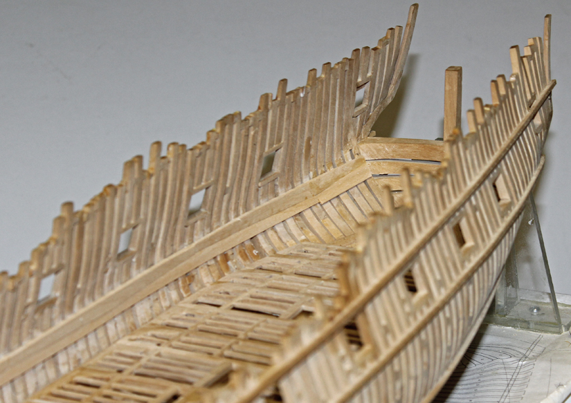
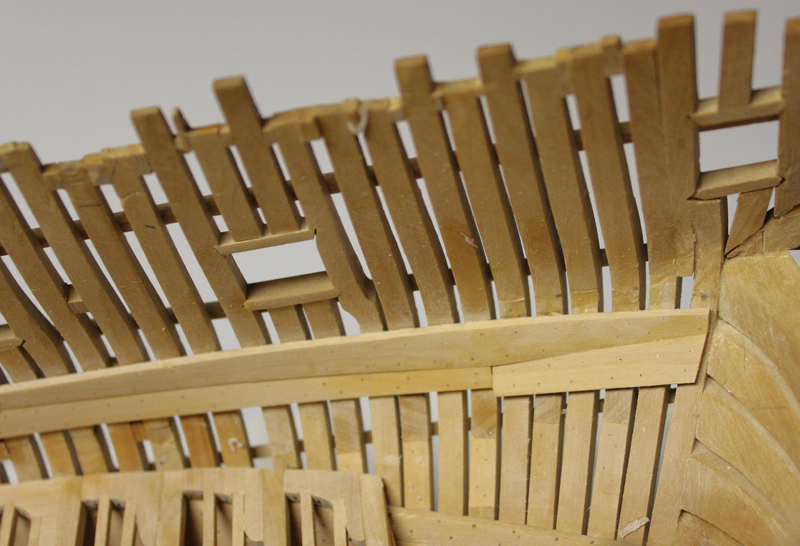
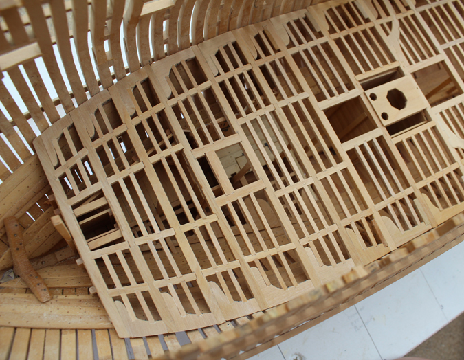
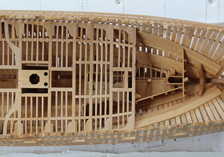
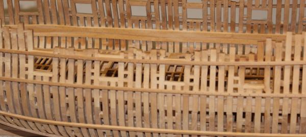
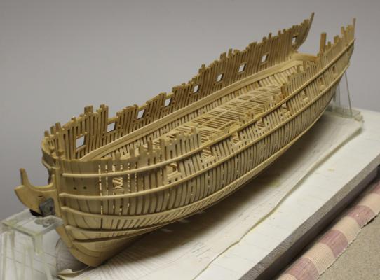
Both strakes of the upper deck clamps are in place. I started with the upper stake which is 4" thick. It tapers down to 3" where it intersects the lower strake. In the pictures that has not been done yet except at the stemson to better highlight the top and butt planking. There in an airspace below the lower strake which stops at the aft end of the upper deck. For this reason the aftmost lower plank is 2" wider than the others. The planks are all treenailed but they are decorative only. In the pictures the wood looks mottled because I wet it down to try and highlight the treenails and the top and butt planking. I am still trying to decide whether I will install the spirketting or treat it like I have the footwaling and leave it off. I am leaning towards leaving it off to allow more light to enter the hull. That decision will be made after the deck planking has been installed. I will be planking the port side, leaving the starboard side open except for (possibly) the waterway.
-
Thank you, Druxey. Right now it feels good to forget about mortises and concentrate on long planks (upper deck clamps) with lots of treenails! The upper clamp is almost done. I'll take some pictures when both strakes are completed.
-
Joe, at this rate you will be watching for a long time. Thanks, Maury.
-
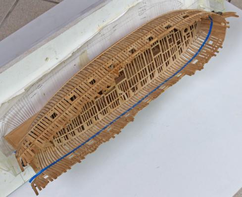
Having spiled all of the planks I can attest to the fact that the sheer strake is not a consistent width for its entire length. Maury, I would suggest you put in the garboard strake next and plank from bottom to top. That way you won't have an infill strake to deal with and there will be less potential for racking the hull.
-
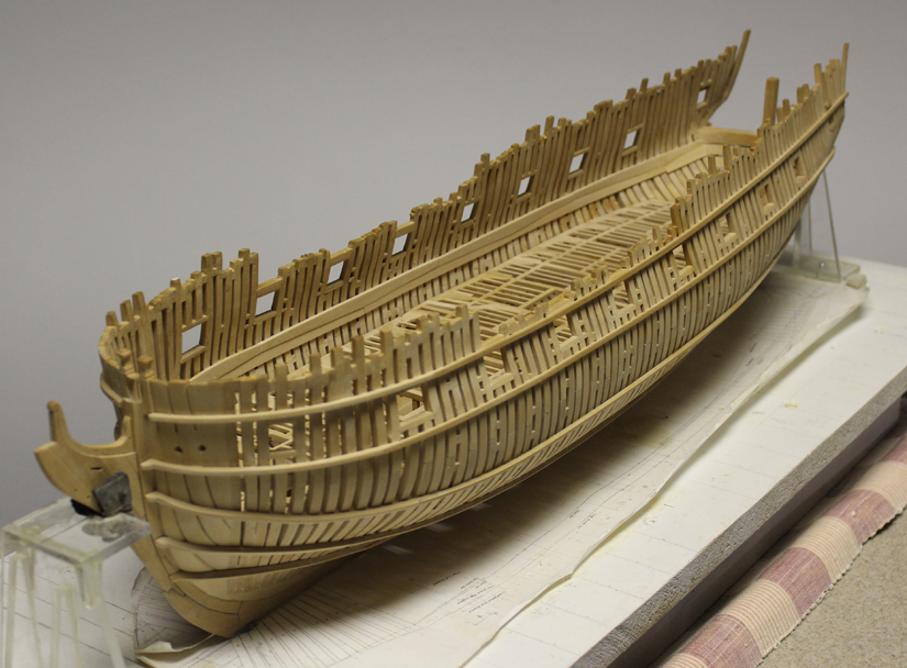
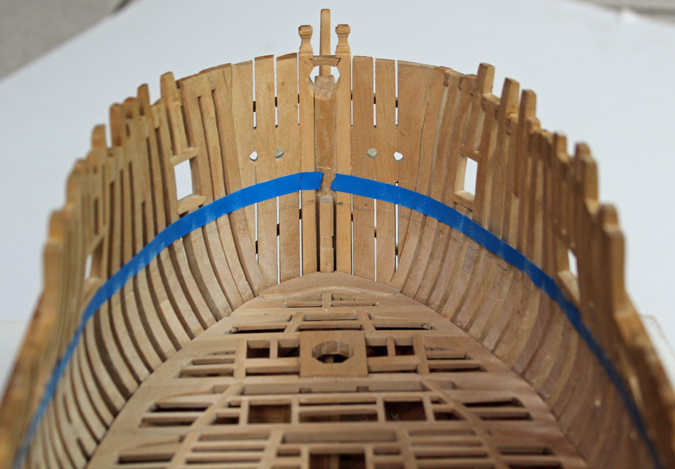
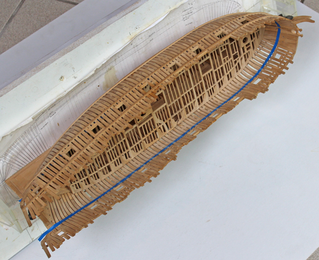
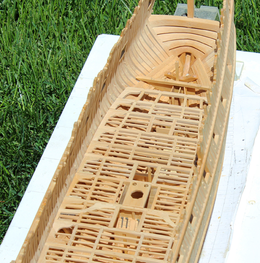
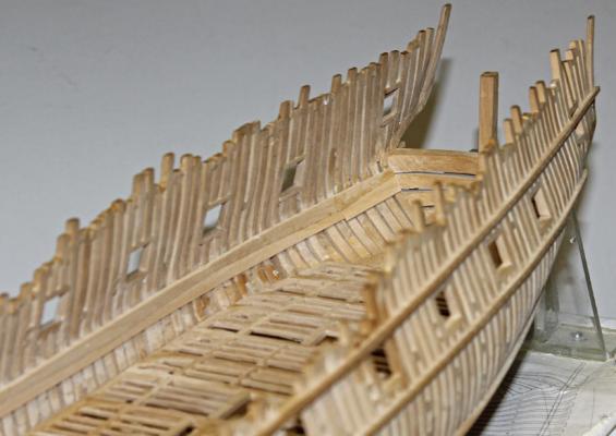
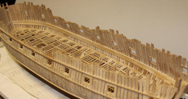
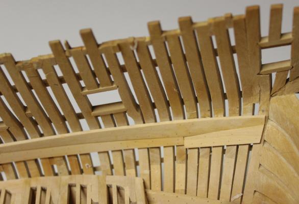
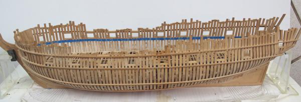
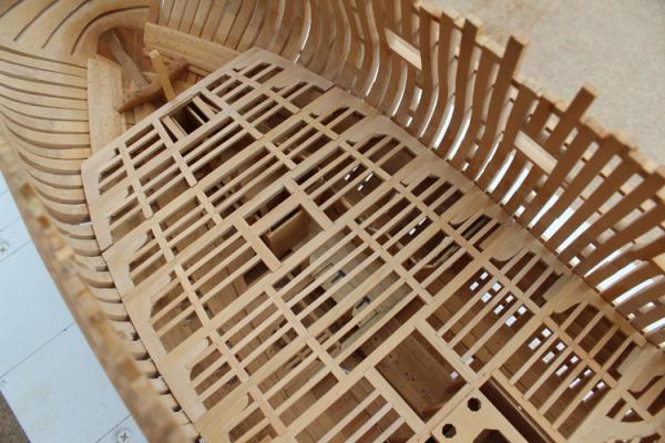
Mark and Pat, thanks for looking in. The mast partner has been installed and now it is time to install the upper deck clamps. There are four strakes and an air space between the top of the lower deck and the upper deck beams. The first task was to measure the top of the beams on the draughts and transfer this to the Mylar. The sheer is less pronounced fore and aft than shown on the Mylar. This height was then marked on the inside of the hull and a strip of tape was placed to ensure a smooth run for this line and also make sure that the line is parallel to the gun port sills. The second photo shows the model laid on its side in order to show the run of the clamp to the stemson. The beams are 7" in height and let into the clamp 1". Therefore I measured down 6" to find the height of the top of the clamp. This line was marked in pencil.

-
Greg and Grant, thank you. I am pleased with her. Let's see...22 month so far and how many more to go.
-
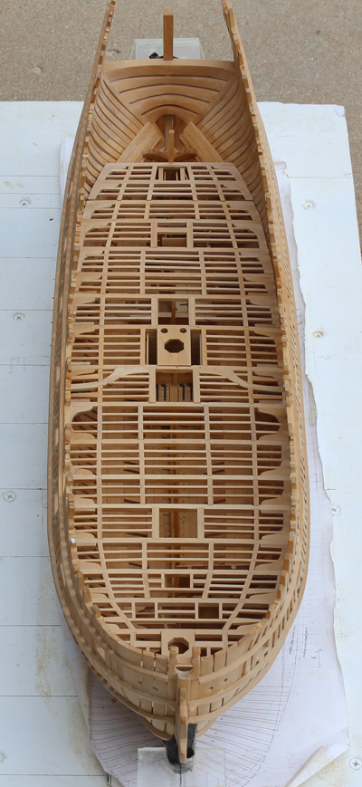
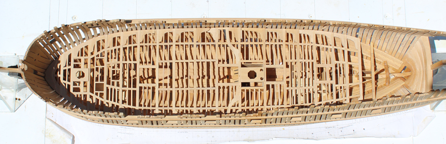
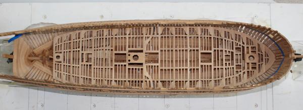
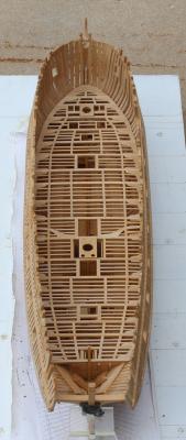
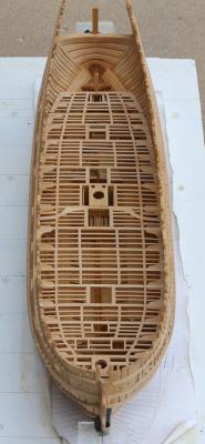
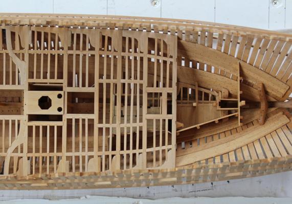
A milestone has been achieved. The lower deck structure has been finished. I have been applying finish to the underside of the beam sets before installing them. The gap in front of lodging knee 17 in the fourth photo occurred because the assembly is not glued in yet and it shifted. The last photo shows it better positioned. I will not put on any upper surface finish until after the decking is installed. Now on to the mizzen partner.

-
Looks good, Bob. As you said, the key to this technique is a light hand and low power from the Dremel. This approach minimizes the stresses put on to the hull from hand sanding.
-
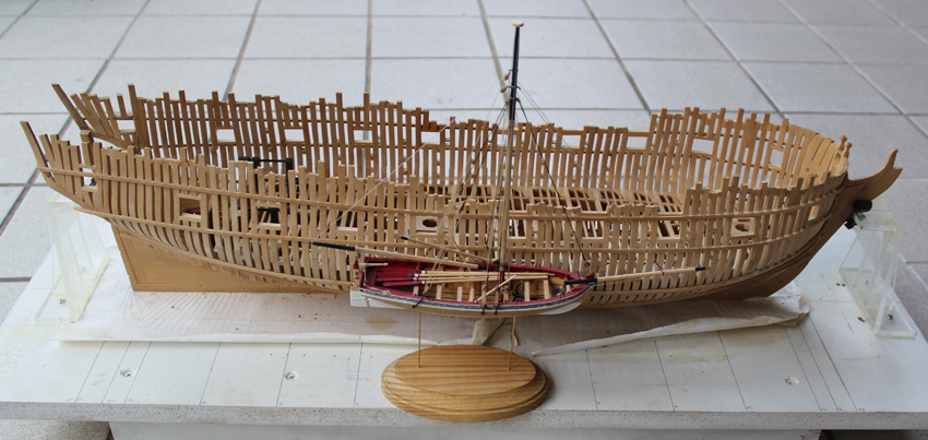
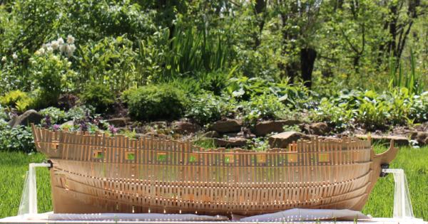
Danny, thanks for the head's up. Not much has been accomplished the last week. The spring here has been particularly cold and cloudy so now that it is a little warmer (50 degrees with a 30 mph wind!) I have been occupied in the gardens. We finally saw the sun yesterday so I took Atalanta sailing in the lawn.


-
It is a kick to see the two of them together, Rocker. Thanks for the suggestion, Ben. I'll think about it.
-
Thanks everyone for your kind comments. Like so much of what we do, if I had left it alone I would have known it was wrong. It really makes you sit up and pay attention when you realize that a 6" error on another deck (1/8" in reality) can have such a profound impact on the next deck.
-
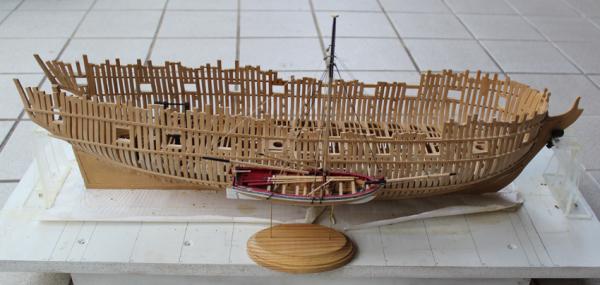
I posted this picture of the longboat and Atalanta under the longboat build log. I am reposting it here for future reference.

-
Thanks, Druxey. I guarantee those lower deck bulkheads will be measured three times instead of twice!
-
Thanks, guys. Just for comparison I took a picture of the longboat next to Atalanta. They are both 1:48 scale.
- 75 replies
-
- 5
-
-
- 18th century longboat
- model shipways
- (and 1 more)
-
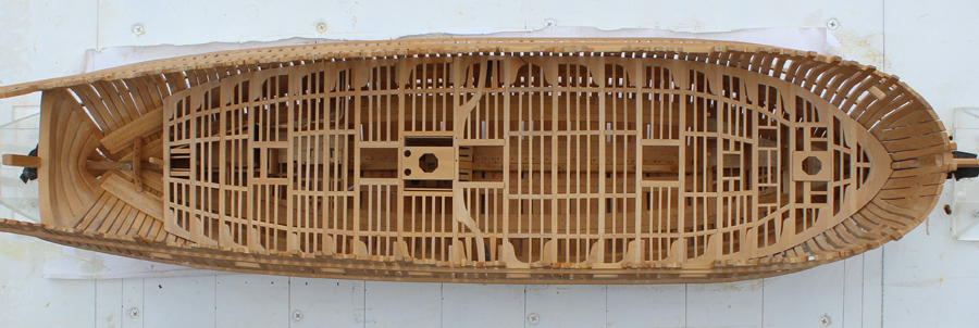
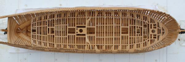
The longboat has been completed so I can concentrate on Atalanta. Beam 16 set has an opening for a ladder to provide access to the aft platform. While looking at this I discovered that the bulkhead for access to the magazine was too far forward. The ladder would either have to be 18" wide or I would have to rebuild part of the aft platform bulkheads. It was just too big a problem to ignore so I removed everything forward of the pillar for beam 16 and rebuilt them. Some of the walls could be reused so it was not a total disaster. I took pictures of all of this but discovered too late that I forgot to put the card back into the camera. The result is not perfect but there is now room for a 24" ladder.
-
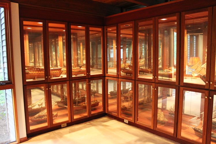
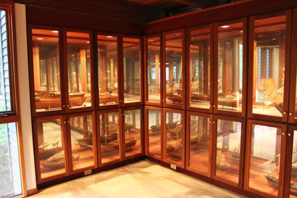
Thanks, Joe. The door frames are mahogany and the shelves are glass to allow the light to illuminate both sheves. For builders who leave one side of the hull unplanked, the mirror allows you to enjoy both sides without having to move the model. Because of the lights, I could not make them completely air tight. So a light dusting once every two years is necessary.
-
Thank you, Grant and Kurt. Chuck, I do not make individual cases for my ships. When we built our house I incorporated display cases into the design of the living room. This will sit along side my Swan class cutter. As far as next projects...back to Atalanta. That will take me at least two years if I don't rig her and sky's the limit if I do. Just as my Victory which is waiting for me to complete her rigging above the mastheads!
- 75 replies
-
- 5
-
-
- 18th century longboat
- model shipways
- (and 1 more)
-
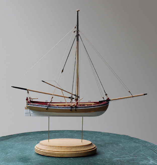
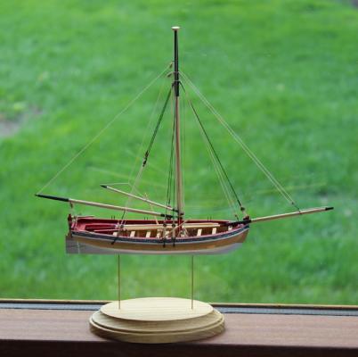
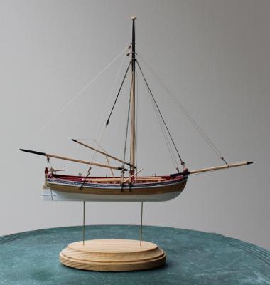
Thanks, Rocker. The boat is so light that the brass wire is sufficiently strong to hold it without bending.
-
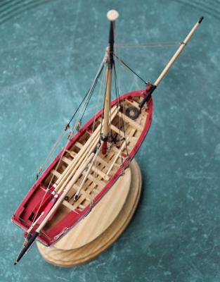
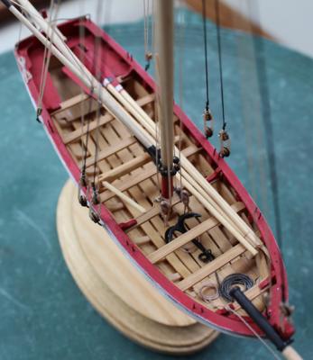
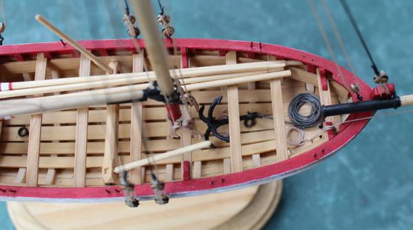
I have finished the remaining details and have permanently mounted the longboat on its stand. The anchor flashing was removed and it was painted flat black. I looked at the prototype on the NMM website and noted that the anchor cable goes through a ring, not through the anchor itself. It is a heavy, dark left-hand twist rope. I happened to have just the thing left over from rigging my Victory and used that instead of the kit supplied material. The rope coils have been added and the paint touched up as necessary. This was a fun build and although I used a lot of replacement material, I think it is a great project that won't take forever to complete.
- 75 replies
-
- 5
-
-
- 18th century longboat
- model shipways
- (and 1 more)
-
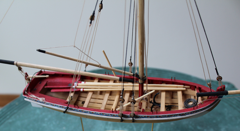
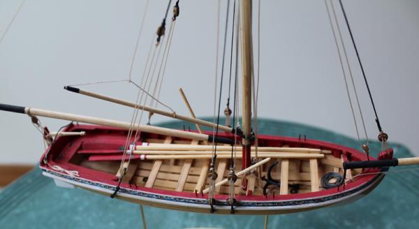
Yes, Chuck, I put the same decoration on both sides. The color rendition is not good in the picture. The red is more...well...red and the decorations really do stand out better.