tlevine
-
Posts
2,033 -
Joined
-
Last visited
Content Type
Profiles
Forums
Gallery
Events
Everything posted by tlevine
-
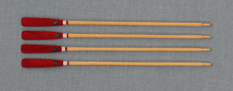
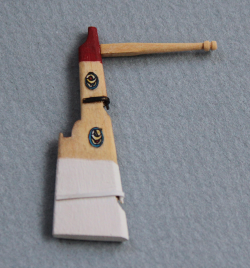
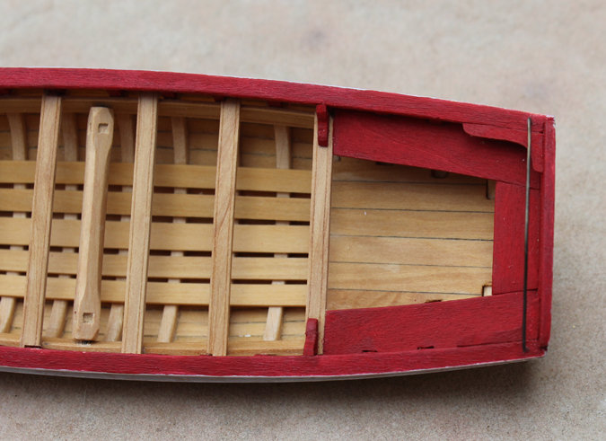
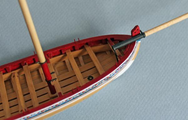
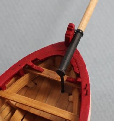
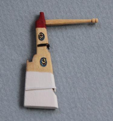
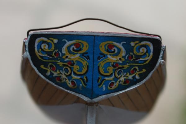
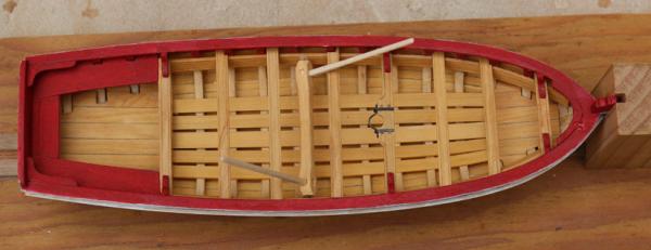
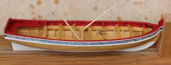
 I had a little fun with the oars. I laid out all eight oars in the boat prior to shaping and found it a bit overwhelming. I decided to go with four oars, instead. The red looked a little boring to me so I added a white stripe for contrast and applied the same decorative medallion found on the rudder to the oar blades.
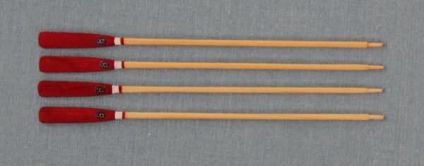
- 75 replies
-
- 5
-

-
- 18th century longboat
- model shipways
- (and 1 more)
-
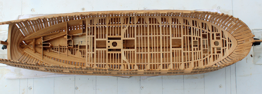
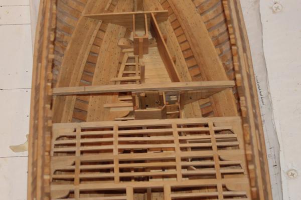
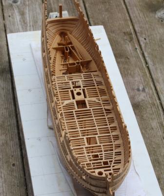
I have finally had a little time to work on Atalanta. Beam 15 assembly has been installed. The hardest part of this assembly was keeping the line of ledges straight across the ship. Slight differences are a lot harder to notice if there is a hatch, mast partner or beam arm visually breaking up the run of ledges.
-
EKE! Thanks a bunch, Sarah. They'll be right for the final pics. Toni
-
The line I use is a black synthetic from www.flyfish@flyfishusa.com. It is called UNI-Thread 6/0 and comes in spools of 200 yds. It is also great for serving lines. Because it is synthetic, knots do not secure well with yellow glue. It is one of the few times I use CA on rigging.
-
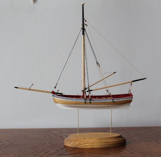
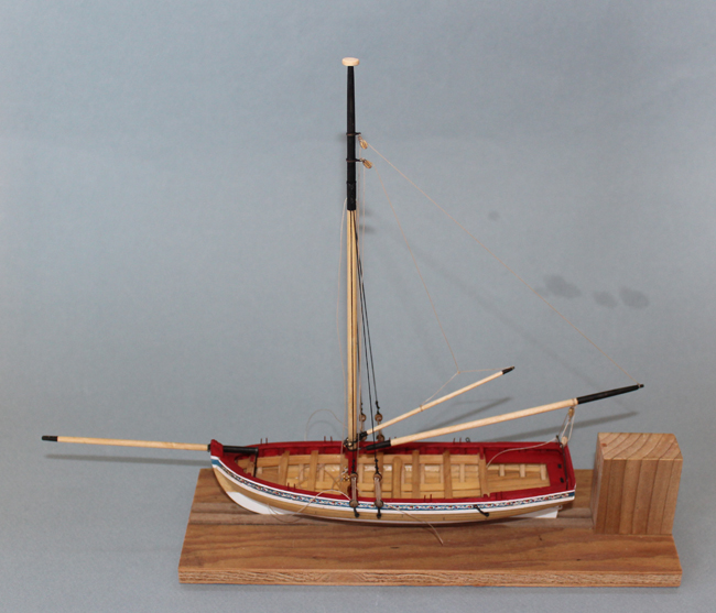
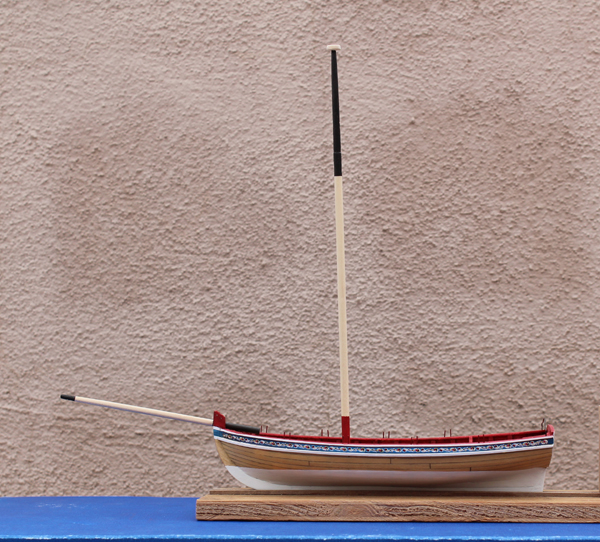
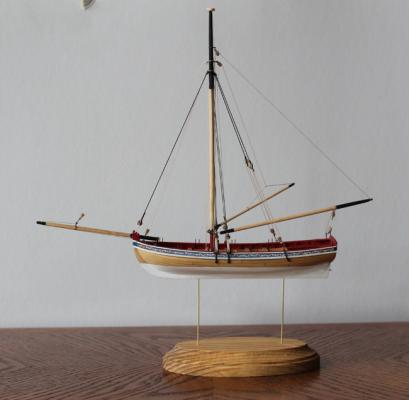
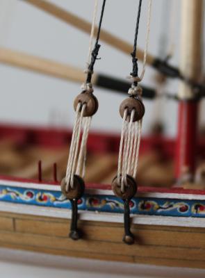
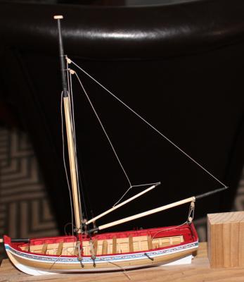
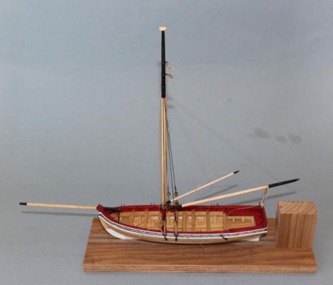
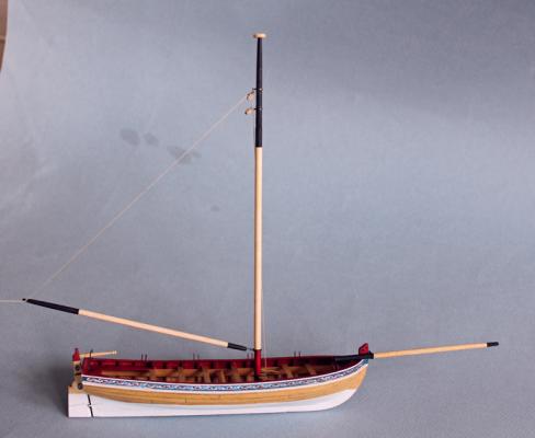
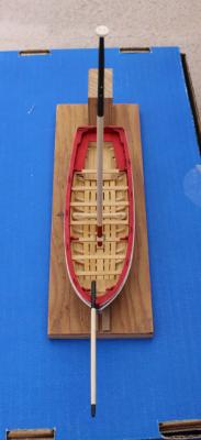
Thanks, Bob. I remade the seizings for the shrouds using fly tying line. It looks much better to me now. The starboard shrounds have the flag halyards tied off to them as well. The rest of the rigging was installed per the directions without any difficulty. I painted the belaying pins tan and permanently installed the rest of the lines. The mounting base is courtesy of Hobby Lobby. I broke the bank on it (79 cents...OK, 85 cents with tax). I sealed and stained it and then applied two coats of Watco's. The holes for the brass wire had previously been drilled into the keel. The rudder was removed for safe keeping. I am getting close to the end of this little adventure. All that remains is making the rope coils, anchor and oars and touching up the paint.


- 75 replies
-
- 4
-
-
- 18th century longboat
- model shipways
- (and 1 more)
-
Thanks Ben and Geoff. I redid the seizings on the shrouds using fly tying thread and it looks much better. I'll post pictures in a few days.
-
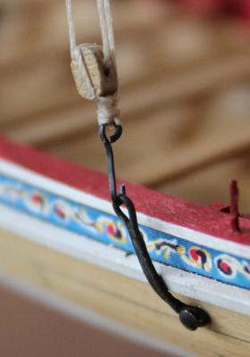
Chuck, the model shows oarlocks at every thwart. The kit show them alternating. It also shows that the deadeyes are rope-stropped and hooked on to the chainplate rather than how it is done in the kit. What is tied on to the backstays? Thanks for all your help.
-
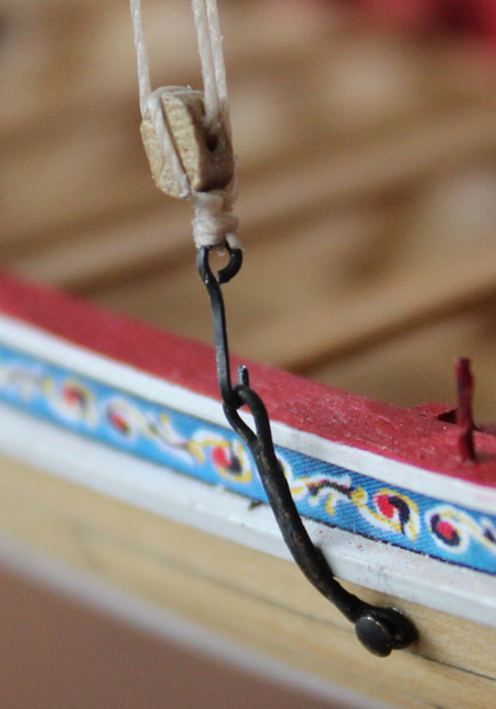
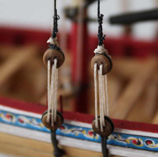
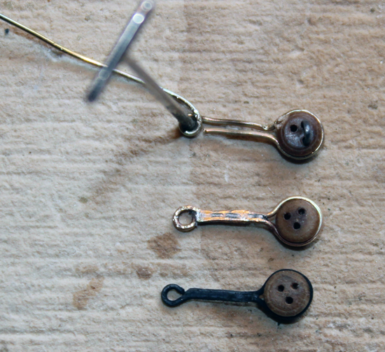
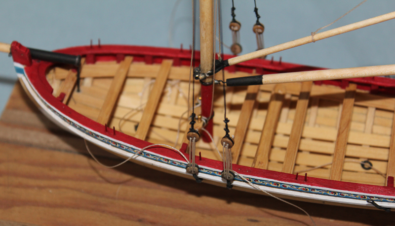
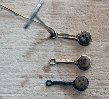
Thanks Ben and Grant. I added the boom sheet and temporarily secured it to the horse. In fact, all of the lines are only temporarily tacked down with dilute white glue so that I can make any necessary adjustments after the line has stretched. The gaff has been made and installed; it is not glued to the mast. The parrel beads in the kit did not blacken well so I will touch them up with black paint later. The rigging line feels like a polyester product and even with stretching and wetting it still has memory. For this reason I wetted the lines with dilute white glue to give it some stiffness without the shine that CA imparts. Sorry for the oddball picture but I wanted to highlight the lines against a dark background. On to the shrouds. I tried to make the chainplates using the black wire provided in the kit. I decided that I would prefer soldering the metal rather than use CA. Unfortunately the enclosed wire did not accept the Tix so I used 26g brass wire instead. The picture shows the sequence of making the deadeye chainplate. There is also a chainplate for the backstay which has two small loops. These are attached to the hull with the provided nails. The shrouds were made with the starboard side first and then the port. They are seized with thread. Three seizings were placed at the deadeye per the drawing in the instructions. However, Chuck only has two on his prototype. I am not happy with the seizings because the thread was too thick. I am not home this week. Once I get back I might remove the seizings and replace them with fly-tying thread, which is about a third the diameter of the provided material. The lanyards are not tied off yet to allow the thread to stretch.

- 75 replies
-
- 4
-
-
- 18th century longboat
- model shipways
- (and 1 more)
-
I completed this part of the build today and had decent results with the following technique. After I tied the line onto the gaff, I wet it with very dilute white glue and formed the peak. I did the same thing with the gaff peak halyard line before I rove it through the "sheave". I have a picture of it in my build log.
-
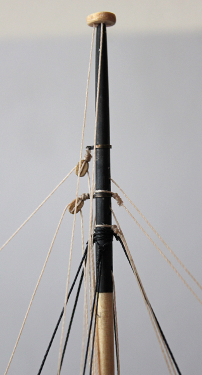
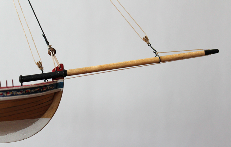
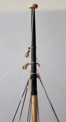
The iron work for the mast consists of three bands. The upper two have horizontal holes drilled through the back strap and the lower one has a vertal hole. The hardest part is putting a hole through the bands. I started by annealing the brass to soften it. I then used a punch to leave a dimple so the drill bit would not wander. The I drilled the hole with a 79 bit with a pin vise. The hole was enlarged to 76. Then I wrapped the brass around the mast. The tails were soldered with Tix. I did not care that solder closed up the hole since it was easy to see the color difference between the Tix and the brass. I reopened the hole and then drilled through the other half of the strap. All metal was cleaned in vinegar and blackened with Birchwood Casey's at a 1:8 dilution. The upper straps have a block attached through the hole. I usually make my own blocks but the ones supplied were consistent in appearance so I simply reshaped them a little bit at the ends. The metal work for the bowsprit is a little more challenging. There are two straps. The first one wraps around the aft end of the spar and extends through the fore platform. I notched the thwart to accept the strap for more stability. I found that the mast kept getting in the way at this point so I would suggest finishing the bowsprit before stepping the mast. This strap is essentially a long piece of annealed brass strip that was wrapped around the bowsprit. The long tails were then soldered together and the assembly was filed to give the appearance of one square piece of metal. The fore strap has a pin soldered between the tails which inserts into the stem. The boom is straightforward. There is a metal hook at the fore end which inserts into the lowest mast strap. The rigging is just for the photo.

-
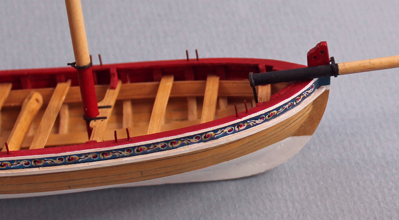
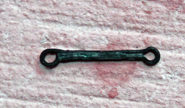
I have gotten a little more work done this week. The rudder is laser cut and only requires tapering fore to aft and top to bottom. I opted to make a straight tiller. There is a mortise at the aft end which inserts into a tenon on the rudder. There are two pintle straps on the rudder. The pins are soldered to the straps. The superior pintle pin inserts into an eyebolt on the transom. The inferior pintle pin inserts into a gudgeon. I did not have the right size tubing for the gudgeon so I made just a simple strap.

-
I have not started rigging the longboat yet but I took a look at the rigging thread. As you know it is tightly wound onto a spindle and appears to be an acrylic-type product. I made up a quick jig and had the same problem you had. I think the problem is the memory in the thread. This can be very difficult to get out of non-natural thread. I was able to get the thread to straighten out by repeatedly wetting and stretching it. I also ran the thread through my hands several times so some of the natural skin oils would be transferred to the thread. After about five minutes of this I tied the thread back onto the jig and it looks much better. I would suggest taking all the thread off the spindle and straightening it this way, keeping it hanging in long lengths and tensioning it while hanging. When I make rope on my ropewalk I always loop it around a hanger and put a large springclamp on the ends of the threads to keep everything straight and under tension.
-
Admiral sounds good to me!
-
Maury, I can take no credit for the shape of the horse. In the directions Chuck makes reference to the old vs. new style horse (flat vs. curved). I went with the new style because it made sense to me. Once I mount the tiller I will adjust the height to allow clearance for the sweep of the tiller.
-
Thanks, Bob. As you can see from the pictures, I am not in Chicago so I will miss seeing the group's projects tonight.
-
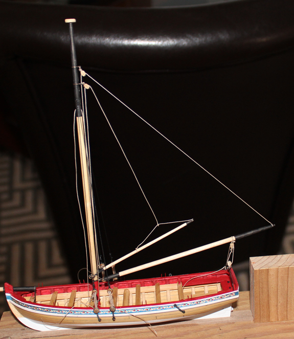
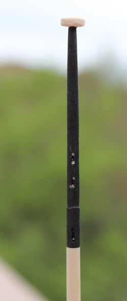
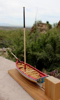
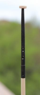
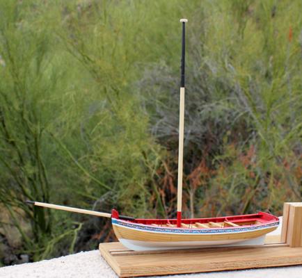
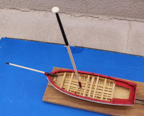
The mast and the bowsprit have been made . There are three "sheaves" in the mast and one at the end of the bowsprit. I used an archival pen for the black areas on the masts. The ink is supposed to be alcohol based and so hopefully it will not bleed when the Watco's is applied to the clear part of the spars. The ball truck has two "sheaves" in it and is temporarily installed. I do not have any metal crafting supplies or a torch with me so the bands will be added later. For the same reason, the bowsprit is tack-glued on to the rail, without its metalwork.

- 75 replies
-
- 2
-
-
- 18th century longboat
- model shipways
- (and 1 more)
-
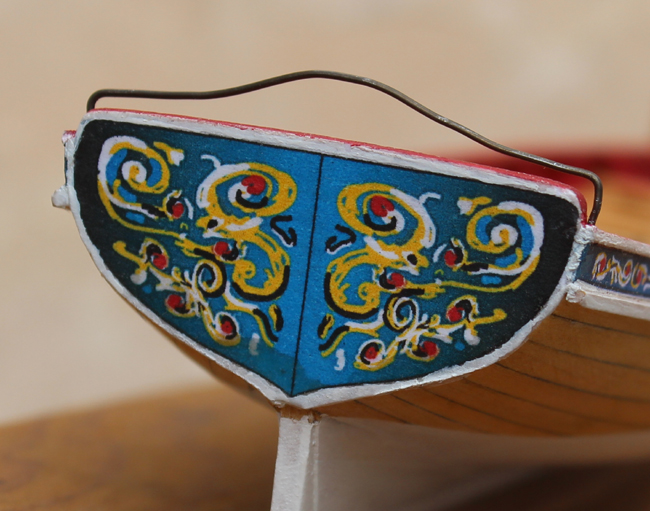
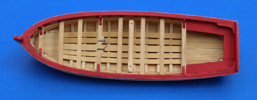
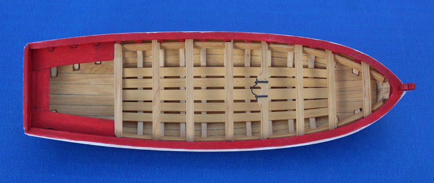
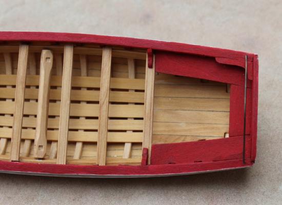
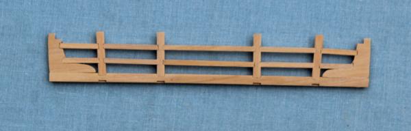
In the instructions Chuck discusses the shape of the horse. The prototype horse is a simple bar. I decided to span the horse over the tiller. As I have not made the tiller yet, the horse is push-fit into holes in the rail to facilitate reshaping it later. The oarlocks have been painted red.

- 75 replies
-
- 2
-
-
- 18th century longboat
- model shipways
- (and 1 more)
-
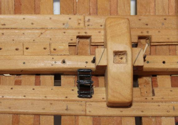
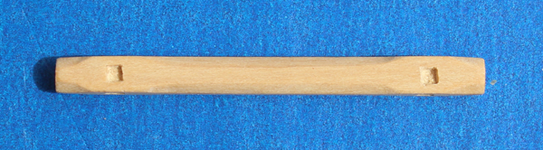
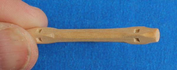
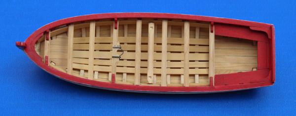
The next project to tackle was installing the knees. These are straightforward except at the bow. I made a template of the curve or the rail and cut a new knee from scrap basswood. I made the windlass from boxwood but the handles are basswood for the contrasting color. I would suggest taking a measurement of the length of the windlass from your model, not from the plans. I discovered (too late) that the internal dimension from riser to riser was less than shown on the plan. As a result, the octagonal ends are shorter than shown on the plans. The square holes were first drawn in and then scribed with a fresh 11 scalpel blade. I found that an Exacto blade was too thick to give me good results. Finally, I used an Exacto to dig out the central area. The handles have been removed for safe keeping. The rudder was shaped and painted according to the instructions. I am on vacation this week and the government frowns on taking combustables on airplanes. Consequently, I did not apply the clear finish or decals to the rudder yet. I'll post a picture after it has been completed.
- 75 replies
-
- 1
-
-
- 18th century longboat
- model shipways
- (and 1 more)
-
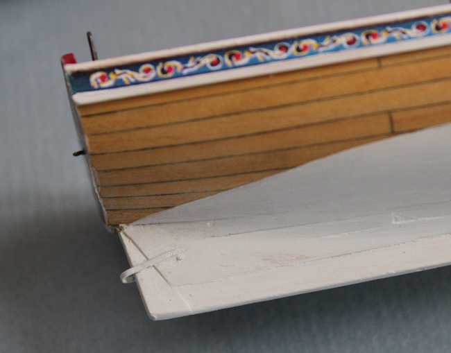
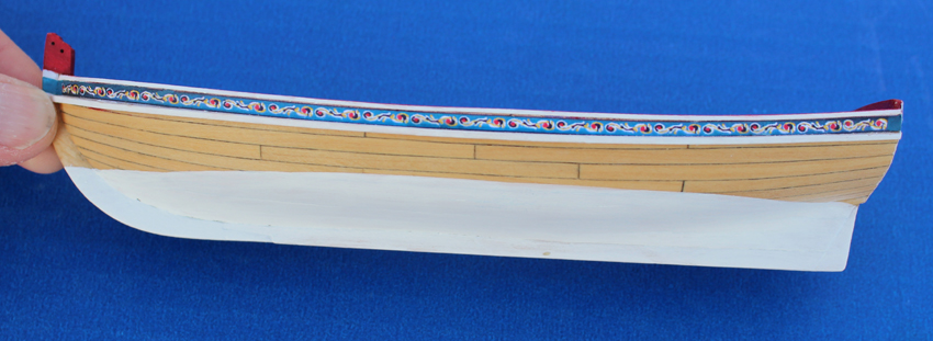
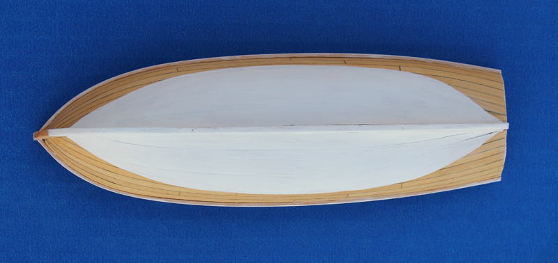
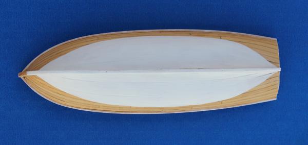
I have painted the cockpit and the hull exterior. The most difficult part of painting the hull is getting a fair water line because of the tuck under the transom. I have applied three coats of dilute white acrylic paint with a light sanding of 320 grit between coats. I will apply a final coat just prior to mounting the mast.


- 75 replies
-
- 3
-
-
- 18th century longboat
- model shipways
- (and 1 more)
-
I totally forgot about the interior glue situation while I was planking. Happily, I only put glue on the bulkheads and on the plank edges,not on the plank interior. The excess ooze was removed with microchisels and isopropanol. (One of the advantages of carpenter's glue over CA.) But between the flooring, the fore and aft platforms and the cockpit seats, very little of the interior planking is exposed anyway.
-
Since I am not taking any modeling projects with me, if the weather is bad I'll finally have time to catch up on everybody's builds.
-
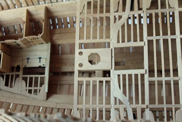
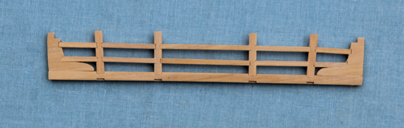
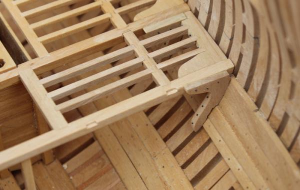
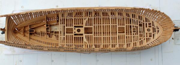
Beam set 13 has carlings for the after hatch and hanging knees. After making several hanging knees and never quite getting the angles correct, I finally stumbled onto an incredibly simple solution. Instead of making a template of the ceiling and then drawing in the top of the beam, I fold a piece of paper along the top of the beam and mark out the shape of the ceiling while making sure the paper does not move off the beam. By reversing the fold, I then check the other side to determine if they are (hopefully) symmetric. The knee in the picture below only needed minor touch-up and tapering aft to fit the narrowing of the hull. Of course, now that I have the hang of things, I am finished with the hanging knees on the lower deck. Hanging Knee Template Hanging Knee Aft of Beam 13 Before I permanently installed beam set 13, finish was applied to the underside of the deck structure and the pillars. The lower well was glued in place and, for extra security, a pin was placed through beam 11 into the midline pillar on the fore side of the well. Beam Set 13 Beam set 14 has only two rows of ledges. The top of the slop room bulkhead on the aft platform needed to be slotted slightly for the deck beam. The pillar passes through a cutout in the fish room trap door and rests on the keelson, like the other pillars. This is as far as the build has progressed. Vacation next week so there will not be any progress for a few weeks. Beam Set 14
-
The problem with the curvature at the bow for the first few strakes and at the stern for strakes 3 through 5 (for me at least) were part of the reason I did not use the provided wood strips. I do not like to edge bend strakes unless they can be well secured to frames underneath (think plank on bulkhead). Looking good, Bob.
- 277 replies
-
- 1
-
-
- model shipways
- 18th century longboat
- (and 1 more)
-
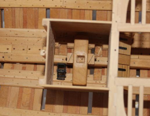
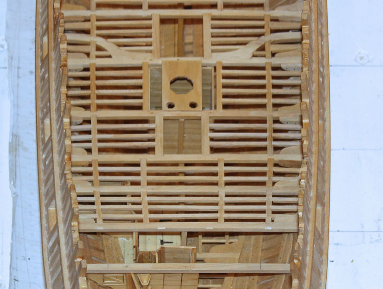
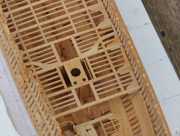
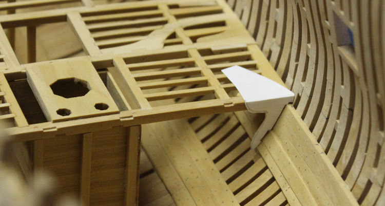
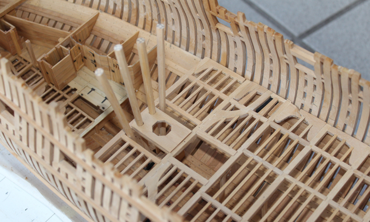
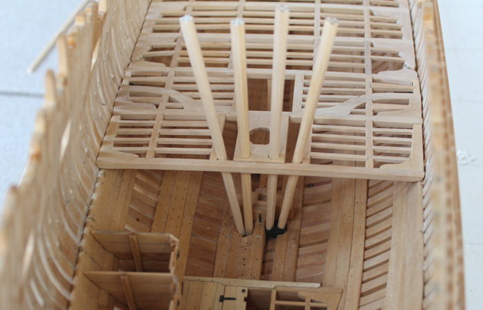
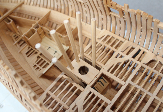
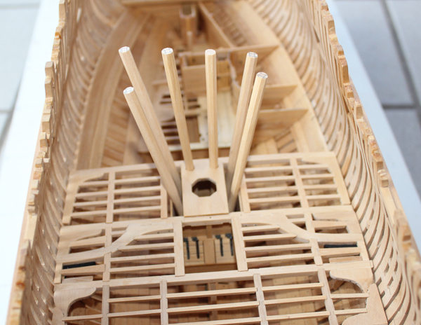
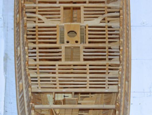
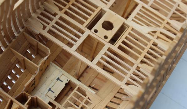
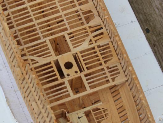
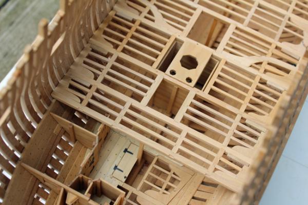
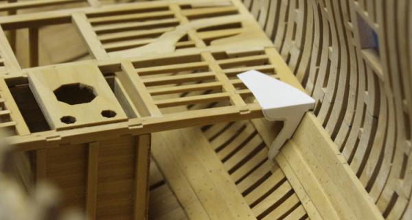
The four aft pump tubes are shown in their future homes. Greg, I got lucky. The ends of the tubes fit perfectly into the chambers. Thanks for the suggestion, Danny. The brake pump tubes are placed in the recesses excavated from the cross-chock of frame 3.


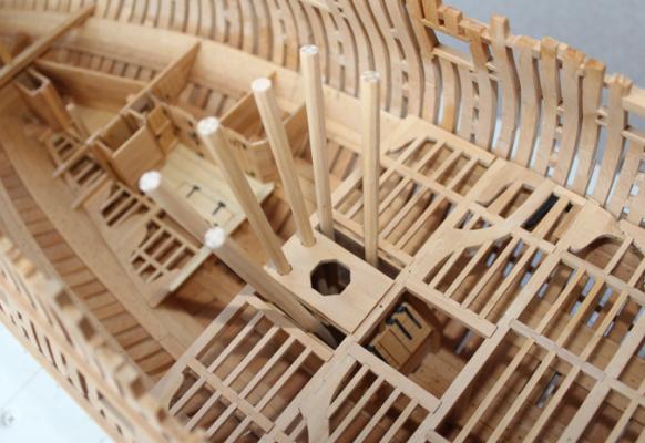

-
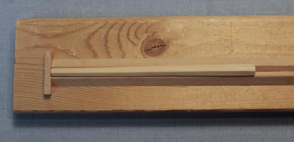
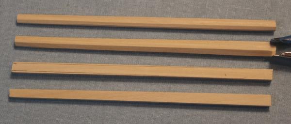
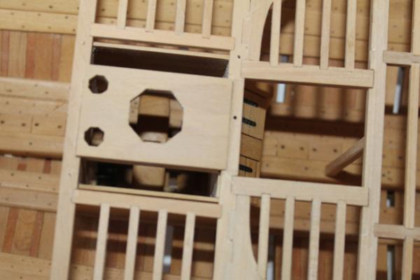
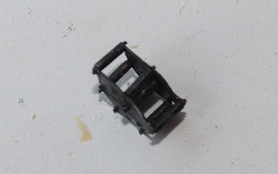
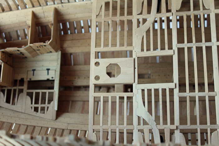
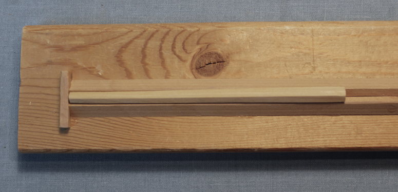
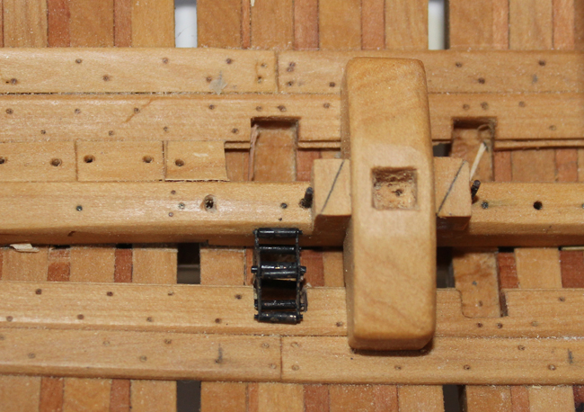
The main mast partner is made the same way as the fore mast partner. There are carlings under the partner which mortise into the underside of beams 11 and 12. In addition to the hole for the mast, two octagonal holes are cut on the aft side of the partner for the pump tubes. There is no hanging knee in this beam set. There are six pump tubes of equal diameter. These were made in similar fashion to making a mast, without the final rounding off of the edges. I first cut a square blank. Next I drew in the required taper and used a chisel to cut the taper. Finally, I put the pump tube in a mast spar jig and turned it into an eight sided tube. Final finishing was done with sandpaper. The photo shows the sequence of forming the pump tubes. I used the photo etch sheet from Admiralty Models to fabricate the pump intake chamber. The spacers are made from brass rod which has been filed down at the ends to form the pins which are protruding from the chamber. The whole assembly was silver soldered and blackened. Here is one of those points where you ask “how much should I install which will never be seen?” I decided to only install the starboard chamber and save the other chamber for (possibly) a cross-section build. Once the lower well is in place and the mast partner installed, it is almost impossible to see the pump chamber.