HOLIDAY DONATION DRIVE - SUPPORT MSW - DO YOUR PART TO KEEP THIS GREAT FORUM GOING! (Only 75 donations so far out of 49,000 members - C'mon guys!)
×

tlevine
-
Posts
2,033 -
Joined
-
Last visited
Content Type
Profiles
Forums
Gallery
Events
Everything posted by tlevine
-
 I have not tried a cup burr. I usually round them off with a file but apparently forgot to do so with this batch of bolts. I am going to try and improve their appearance by filing them flat and then painting the shiny end or possibly removing and replacing them.
 -
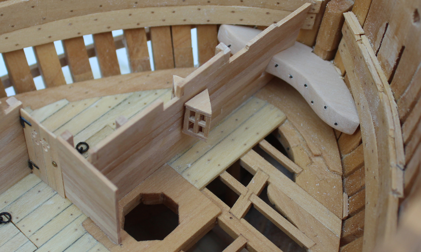
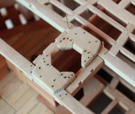
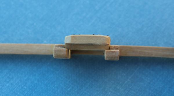
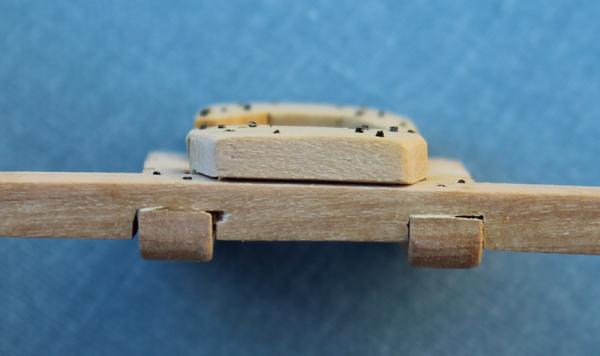
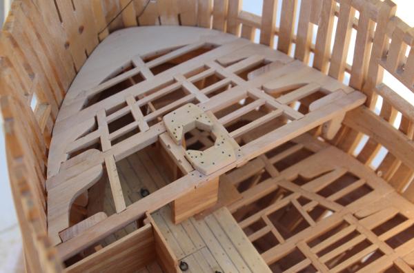
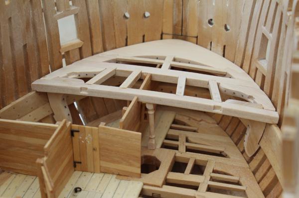
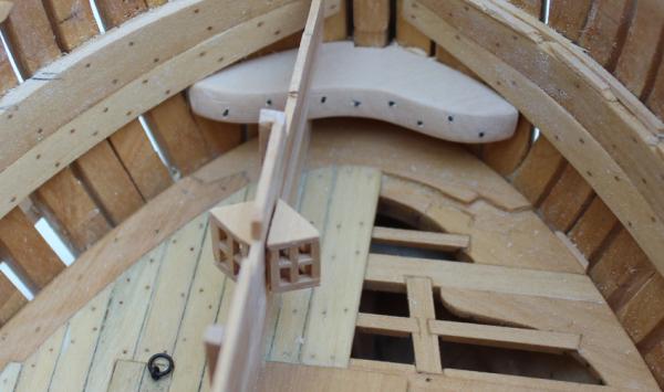
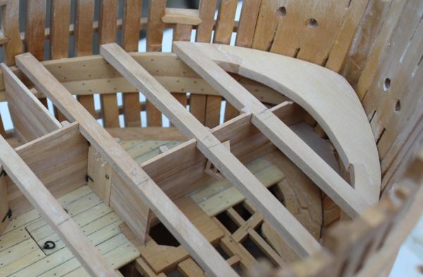
The hand is mostly healed so I was able to get a little work done this weekend. The fore mast partner is located between beams 2 and 3. Unlike the lower deck, the fore and main partners on the upper deck are complicated affairs. The carlings are let into the beam from below but stop one inch below the top of the beam. Fore and aft cross chocks are mortised into the carlings and the beams. Finally, the four corner chocks are mortised into the cross chocks and the carlings. The cross chocks have a round-up to match the beams. A total of 32 bolts hold this assembly together. Sorry for the picture quality but these were taken before I finish sanded and cleaned up the assembly. The blue discoloration is from the droplet of blackener I put on one of the bolts that was damaged during insertion. I put plain water on the area later and it is not longer a problem. The completed assembly is glued to beam 3 but dry-fit to beam 2. The brass wire will keep the assembly in place as I make the knees and carlings. You can see that the blue color is gone. I have started work on the beam 3 assembly. The lodging knees are attached to the beam but everything else is simply press fit in place. I was lucky enough to have bright sun to take pictures in. Yes, I know, light overcast is best to prevent shadows. But sunlight picks up gaps and other irregularities better. You can see the difference between beam set 2, which is finished and glued and beam set 3 which is still in the "rough" stage.


-
Jim Byrnes Model Machines
tlevine replied to Mahuna's topic in Modeling tools and Workshop Equipment
My preference would be for a serving machine. The reason for this is that I already own an OSS and even though it is designed for macro-carpentry I would be hard-pressed justifying a replacement. I guess that's the same reason I still use an ancient Dremel table saw with an Accurizer! -
Thanks for your concern, Druxey. The hand is pretty swollen today but I don't think there was any permanent damage. And right now, the culprit wants to play "squeeky-toy"!
-
Thanks, Jim. I was hoping to have pictures of the fore mast partners this weekend but I hurt my hand (actually I made the mistake of breaking up a dog fight and ended up the only casualty). Next weekend...
-
Dan, your problem results from the run of the planks near the bow. Take a look at the first page of my build log to see what I mean. If you need some additional pictures, let me know and I will take a few to illustrate the point and send them to you.
-
Alex, the metal parts I am more likely to step on, especially if they are sharp!
-
Lots of great ideas. Thanks everyone. As far as cleaning... As I am the "admiral", if I make a mess the only person I can complain to is myself. I try not to let it get too out of hand but if you get something crunchy in your dinner and it looks like a carling, oh well.
-
Thanks everyone for your suggestions. Ed, I particularly like your idea of forgetting prevention and simply cleaning along the way. I have started keeping the model in a separate room and only bringing it to my workspace (ie the kitchen) when necessary to minimize the dust.
-
Thank you John, Ryland and Joe for your compliments. One of the big problems I am having is keeping dust and debris out of the lower reaches of the hull. I currently have a piece of aluminum foil that I keep molded to the lower deck aft of where I am working but this does a marginal job at best. Any suggestions besides an air compressor?
-
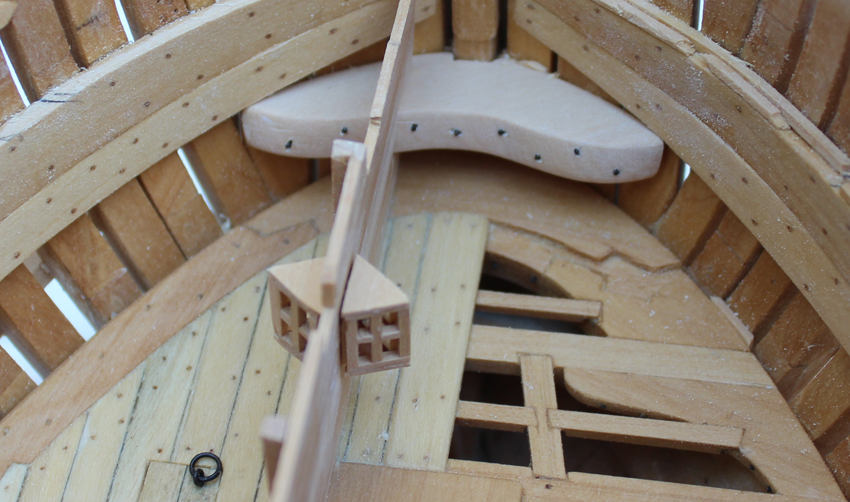
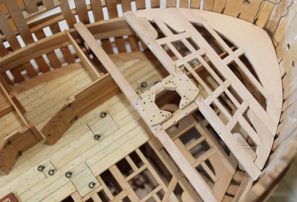
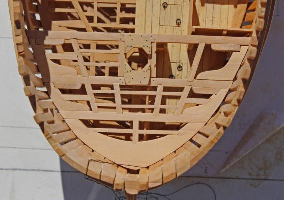
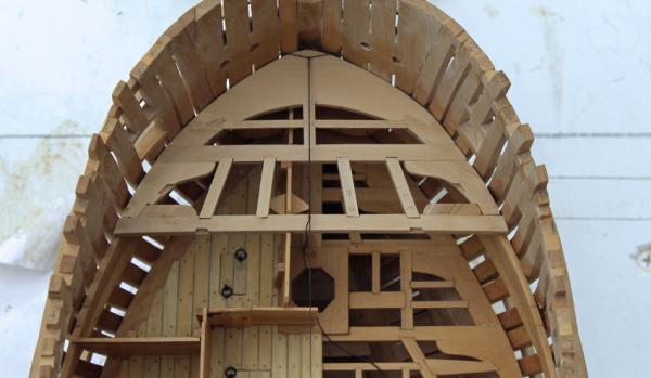
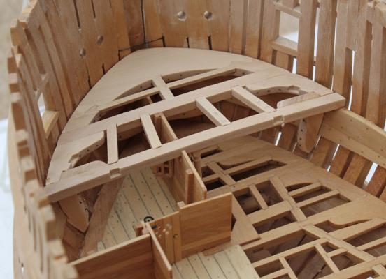
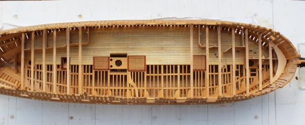
The framing for the upper deck has started. Hopefully it will look better than the lower deck framing. The biggest difference between the two decks is that there are hanging knees at every beam, slowing down the process considerably. In order to accurately mark the centerline I have wrapped a loop of thread through the ventilation spaces of the hawse pieces. A second thread is secured to this loop and attached to the stem. The carlings are dry-fit (and at least one of them needs replacing ) and still need their notches for the ledges cut. The pillar has a tenon superiorly to fit into a mortise on the undersurface of the beam. Inferiorly it is simply glued to the deck. The large gap between the hanging knee and the frames occured because I have chosen to omit the ceiling below the deck clamps.
-
Will it be available in time for the NRG meeting?
-
Thank you Druxey. A hay-filled mattress... How inviting , Kevin . Hammocks take up more room lengthwise than a bed and so would not have fit into these small rooms.
-
Thanks for your input, Danny. I was thinking the same thing. Thanks, Joe, for looking in.
-
I agree with you completely, Druxey. When the beams are finally installed I will add the filling pieces. Would the pieces be oriented horizontally like the door header or vertically?
-
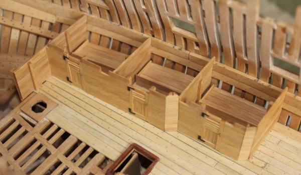
Ben and Tom thanks. I have installed the bed platforms (three aft and one fore). These are simple structures with a higher edge medially to help prevent rolling out of bed in rough weather. Once everything was glued in place I applied a single coat of Watco's. As I may have mentioned before, it appears their formula may have changed because it is causing a significant yellowing of the wood. With the Costello box it is not an unpleasant yellowing...almost an aging look. Compare these pictures with the bare wood pictures on the preceding page. But I am not sure it works well for the holly. Well, I have several months to work that out.


-
Beautiful work on the rudder and its metalwork. That Smith torch makes silver soldering much easier and (IMHO) safer with its small flame.
-
Robin, I agree that the lantern positioning looks odd from above but this is the location on the NMM plan. There is no armament on the lower deck and the magazine is aft. Whether a lantern is mounted or carried in to the room, some type of illumination would be required for these storerooms as there is no natural lighting this far forward.
-
Danny, thanks for the heads up on the cathead. Someday I'll even get that far! Everything looks great.
-
Thanks for your encouragement, gentlemen. As far as interior fittings are concerned... My perspective is that I like to see the carpentry and do not have much interest in adding things like barrels, ballast, shelves, pots and pans, microwave , etc. My next build will probably be a cross section which will show all of those items (except possibly the microwave). This is also why I am only building out the port side and leaving the starboard relatively bare. Those are your hinges, Greg. Blackened with Birchwood Casey and attached with Elmer's yellow glue after the underside had been sanded to bright brass. I found this worked better than epoxy.
-
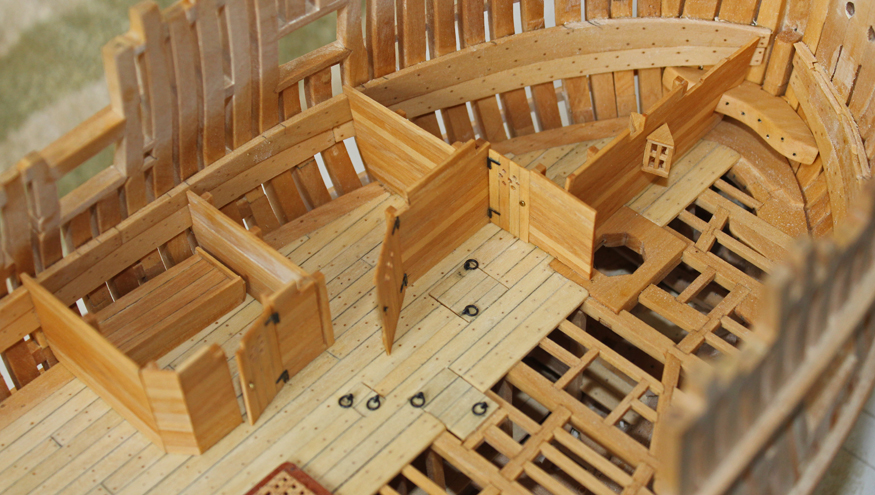
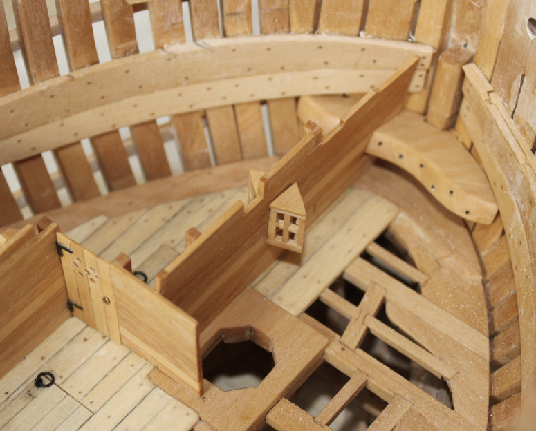
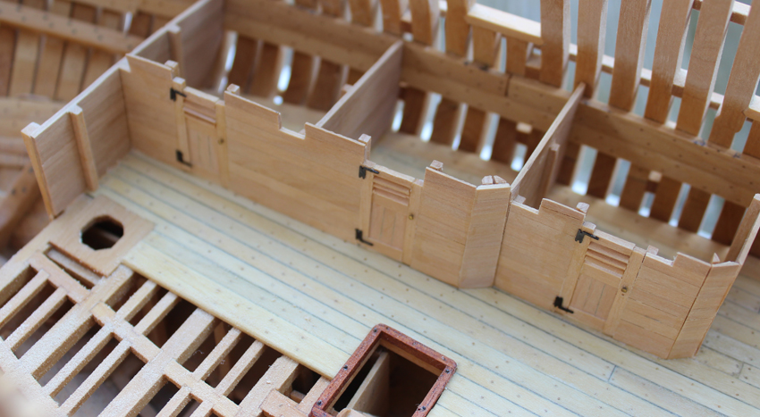
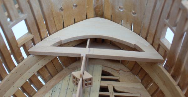
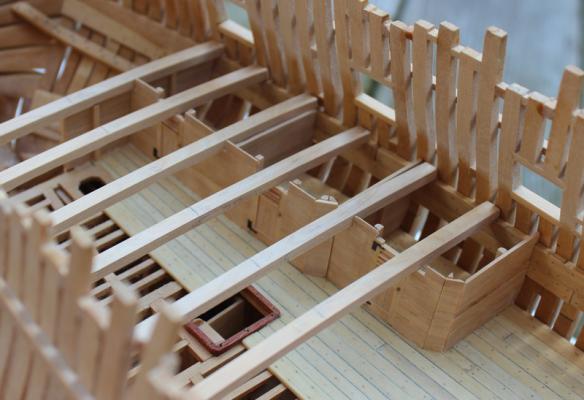
Over the last few weeks I have been continuing work on the lower deck bulkheads and doors. The fore doors are a simple affair with drilled holes for ventilation and a z-brace on the inside. The hinges are from the photoetch sheet from Admiralty Models and the door knobs are brass pin heads. Because the doors are very plain looking, I left two of them ajar to break up the line of wood paneling. The aft doors are more visually interesting and so are shown closed. These doors have a lower "floating" panel and ventilation is via louvers. When making the doors it is important not to simply notch the top of the door for the beams but to notch the entire header where it would interfere with opening the door completely. There is a lantern on both sides of the bulkhead separating the boatswain's store room (port) from the gunner's store room (starboard and not shown). The small piece of wood between the 3rd cant frame and the lower deck hook is a piece of scrap that fell in the space. The next task was to make the upper deck hook and eking pieces. On the lower deck, the hook was rabbetted for the run of the deck planking. On the upper deck this is not the case. Although not very apparent in the photos, there is a round-up on the hook to match the round-up of the beams.


-
Try making your eyebolt by twisting a piece of wire around the appropriate diameter drill bit to give the correct ID. This leaves you with a "pig tail" rather than a single piece of wire to insert into the deck. Drill the hole in the deck slightly smaller than required and then screw the "pig tail" in to the hole after applying a little two-part epoxy. This gives a lot more surface area for the epoxy to take hold.
-
What beautiful craftsmanship. You have done all of this in 8 months? Incredible. AntiSpiral mentioned that there is a Russian forum you have the build posted on as well. Would you mind posting a link to that? Thanks.
- 227 replies
-
- 2
-

-
- cumberland
- 74 gun
- (and 1 more)
-
The update was definitely worth the wait. She's beautiful. You said she is smaller than a Swan class...approximately what is her length? How much internal detailing are you planning?
-
Looks great, Bob. I also made the breast hook flush with the caprail.