HOLIDAY DONATION DRIVE - SUPPORT MSW - DO YOUR PART TO KEEP THIS GREAT FORUM GOING! (Only 13 donations so far - C'mon guys!)
×

tlevine
-
Posts
2,032 -
Joined
-
Last visited
Content Type
Profiles
Forums
Gallery
Events
Everything posted by tlevine
-
 Thanks, Danny. I should have checked your build. It just seems so odd since the shape detracts from the strength and stability of the step.
 -
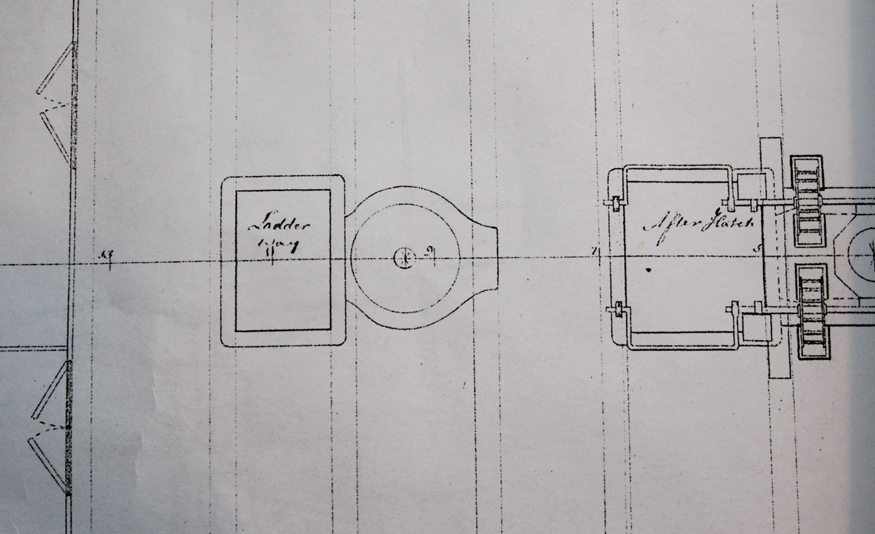
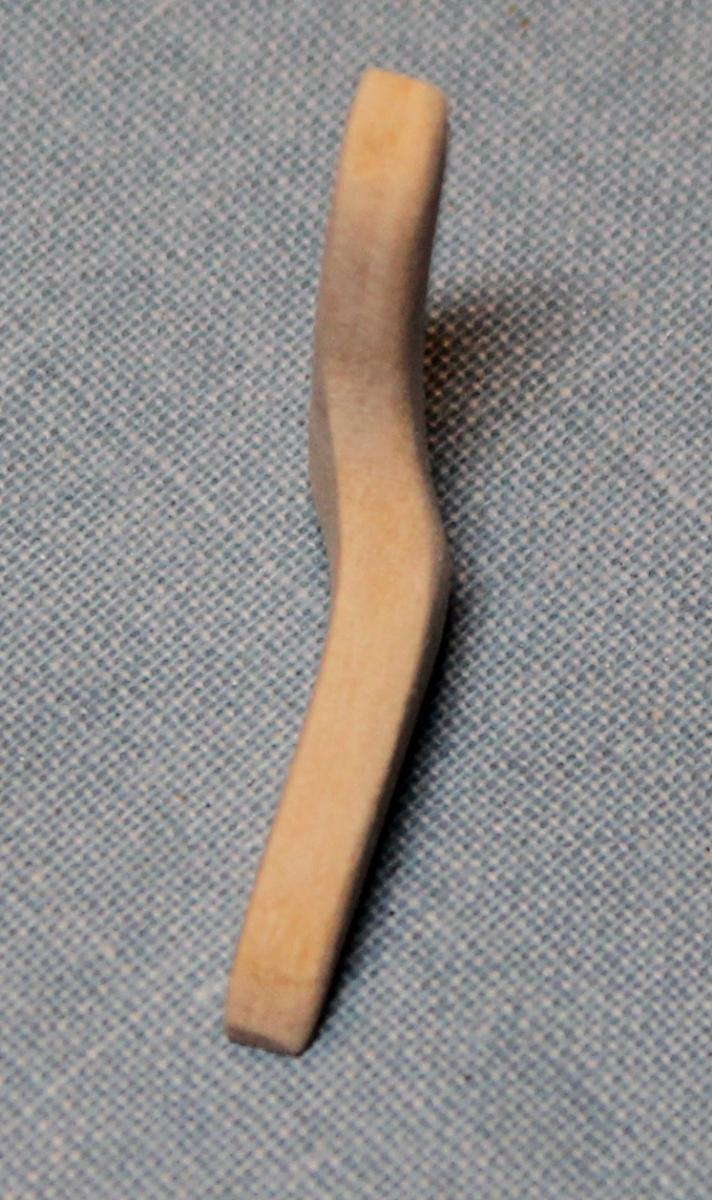
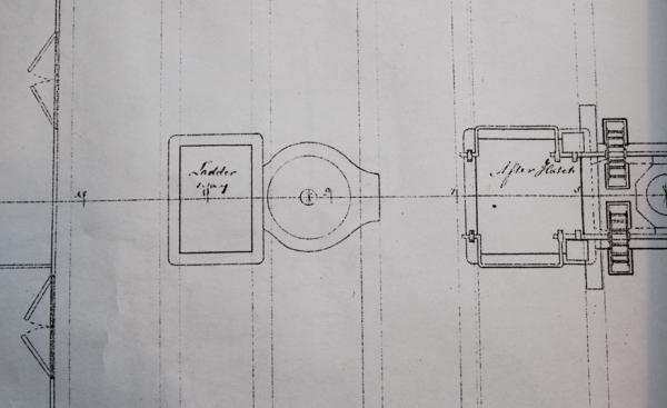
Work progresses slowly on the upper deck framing. No pics this week. The next significant structure to construct is the capstan step. In TFFM this is shown as a roughly rectangular block of wood inserted between the beams and its supporting carlings. On the Atalanta plans there is a ovate structure instead. This would seem to have much less strength than the one suggested by David. I am looking for some help on this one. Is the structure shown on the plan correct? Or is this seated on top of a rectangular step?
-
Druxey, I need all the cheering I can get. Greg, I don't have any grandkids taking up my time. Just work, the house, the dog, the horses and keeping the husband in line! Elia, hopefully you'll get more time soon.
-
Thank you everybody. JD, I spend 8-10 hours a week in the workshop (aka kitchen counter). Please remember that the first sawdust was made in July, 2011. I figure that I am on the 5 year plan... and that is without masting her!
-
Wow! Not only is the craftsmanship great, but the tutorial breaking it down step-by-step is even better (if that's possible).
-
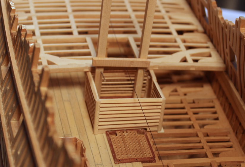
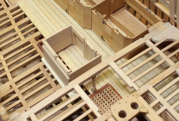
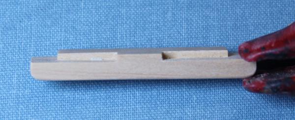
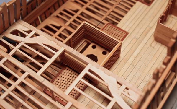
John and Elia, thank you for your kind comments. Thanks for all the Likes as well. A little more has been accomplished this weekend. I have applied the finish to the pantry. Beam set 14 has been installed and beam set 15 is in progess. The middle carlings are larger to support the capstain partner. Unlike the carlings for the mast partners, this piece is installed like a regular carling (ie from on top) rather than under the beam.


-
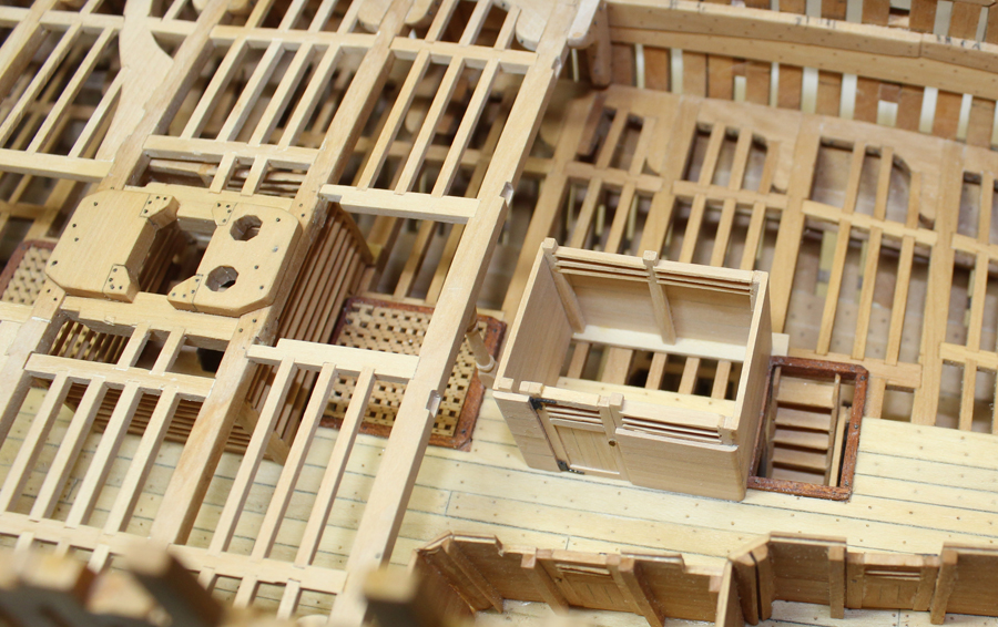
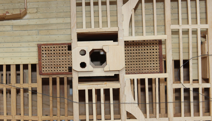
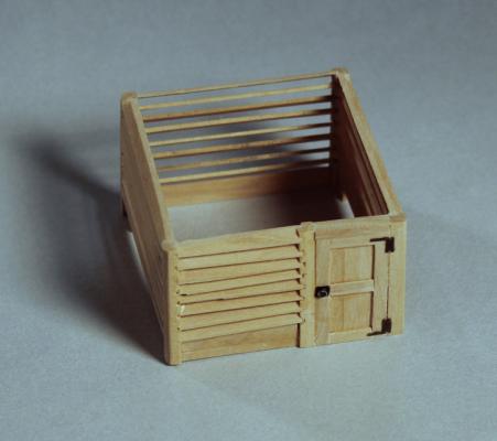
The pantry is located on the lower deck in front of the ladderway. It is constructed with partially louvered walls like the sail room. In contrast to the sail room, there is a standard swinging door rather than a slider. I finally tried to cut the slat mortises on the table saw. I had to free-hand their locations as I could not quickly develop a jig. A piece of 1 x 1 mm brass clamped down to the saw table would have done the trick but I did not have any and when I tried to cut wood this dimension it disintigrated. I think they came out reasonably well. Next time I would run out to the model railroad store a few towns away and buy the brass square as the mortises look better even though once the slats are inserted there is really no difference in appearance. The plan shows the door underneath the beam (not installed on these pictures). I found this odd because this would limit the door height and also because a support stanchion could be incorporated into the door frame if the door was located between frames. I built the door in the location shown on the plan. I also decided not to put a pillar under beam 13 as this would end up in the middle of the pantry and restrict the storage possibilities. A stanchion on the starboard wall will be the substitute for the pillar.
-
Dan, just be sure to play around with that airbrush off the model first. BTW, my paint was applied with a brush. When it came to applying paint near the masking tape, make sure that the brush is almost dry and paint from the tape down to the wood. As soon as the paint is dry-ish get the tape off so it does not tear out the paint. If you have to apply a second coat (I did) stay away from that nice crisp line by masking over it with the blue painters tape. Don't burnish it and get it off as soon as the second coat is applied. You'll do just fine.
-
Your talent is unbelievable. What are your going to cook on that stove first?
-
With the problem this gave me, that is exactly what I would do next time. Did I just say "next time?!"
-
Christian, Ben and Druxey thank you. And thank you, everybody, for the "Likes". David, I use different chisels depending on the job. For the mast partners I used a 10 mm Two Cherry and a 1/8" Stanley Sweetheart chisel. On the smaller mortises I use a 3 mm Dockyard chisel. Mark, this was definitely a case of 1mm here and there making a huge difference in the pump tube alignment. Luckily, the repair is barely noticable.
-
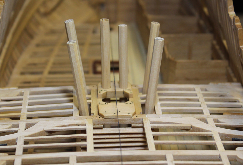
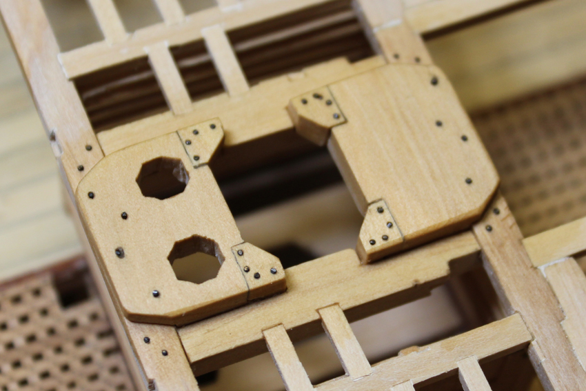
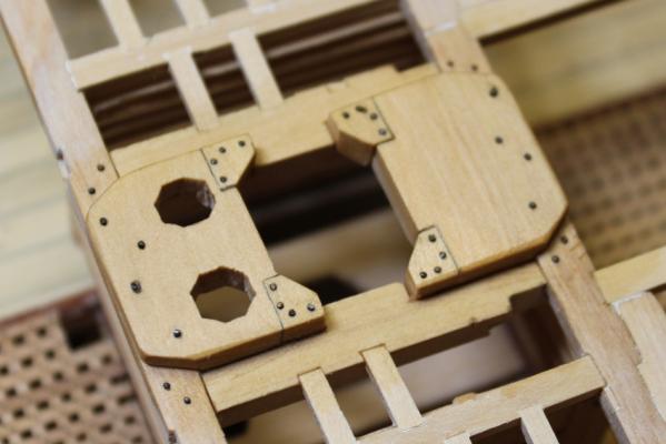
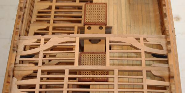
The chocks were fitted next. The edges were highlighted with pencil to make the seams stand out. The assemblies were then glued in place. The aft partner was glued using the log pumps to help alignment. After the glue was dry, I cut the mortises for the ledges between the partners carlings and the middle carlings. Because of the locations of the pumps and the main topsail sheet bitts, only two ledges would fit. The multiple bolts were added and a coat of finish was applied to seal the bolts in place. I typically dry-fit the bolts, only using glue if the hole is too large. The last photo shows how it will look with all six pumps in position.

-
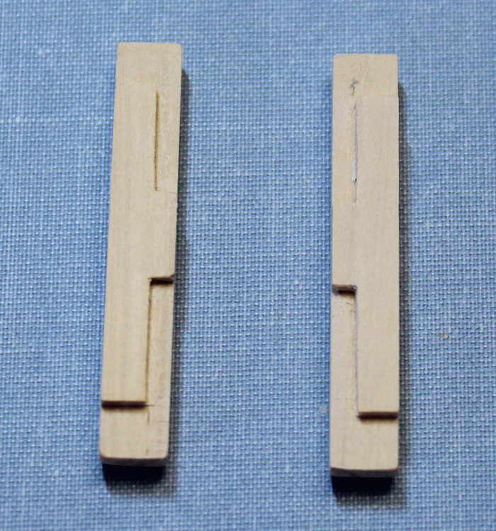
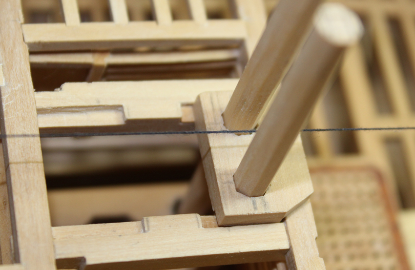
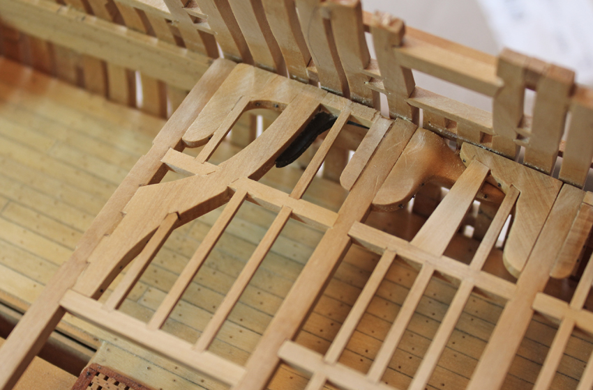
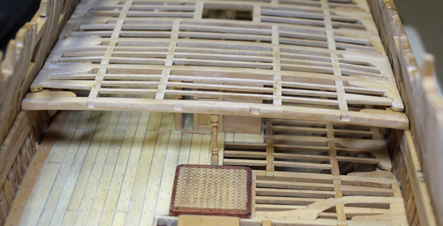
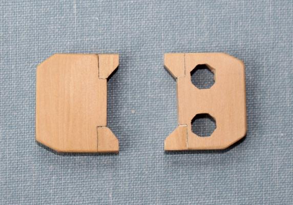
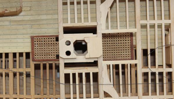
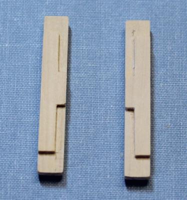
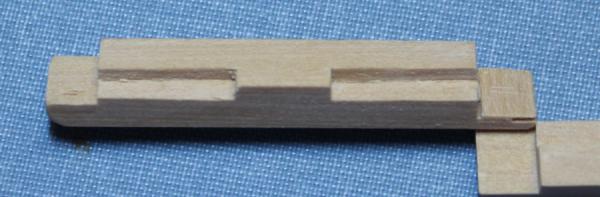
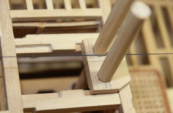
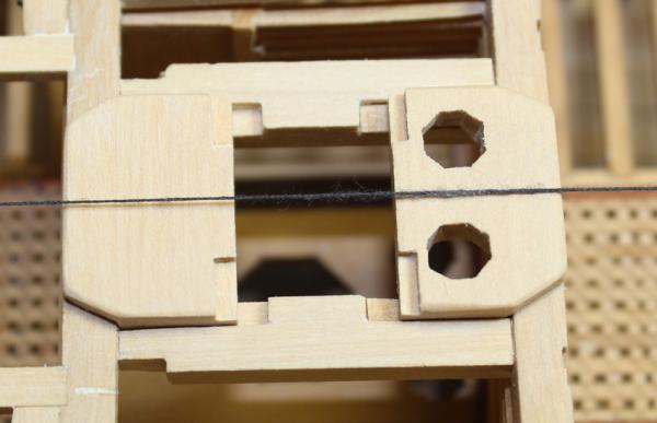
Thanks everyone for the "Likes". My next project is beam set 12, which includes the main mast partners. The beam set itself is straight-forward. The main mast partners is similar to the fore mast partners...only larger. The carlings are half- mortised into beams 11 and 12. I had previously made the decision not to cut the mortises on beam 11 ahead of time because any mistakes would be very obvious. My intention was to cut them in once I had the mortises cut on beam 12 so they would be exactly parallel. I could not cut them to my satisfaction because the upper well was in the way of the chisel. I did not wish to remove the upper well and possibly damage it so I faked the fore tenon. In the pictures you can see the recess cut into the carlings for the partners as well as the difference in the thickness of the fore and aft tenons. The next pictures show the fore and aft ends of the carlings after they were installed and before final sanding. The aft partner was addressed next. This has octagonal holes cut into it for the pumps. Now comes the tricky part. These log pumps extend through the previously cut holes in the lower deck main mast partner and insert into the pump intake lateral to the keel. They also need to be perpendicular to the keel and slightly canted away from each other. The holes in the lower deck partner needed to be "adjusted" to accommodate this three dimensional arrangement. That's a euphemism for totally trashing the holes. After the aft partner was temporarily glued in place, I inserted the logs down to the hold. I made a veneer of boxwood and planked over the lower deck partners to disguise the error. In the third photo you can see the widened hole in the lower deck partner before the repair. The fore partner was made and the last picture shows it in place.


-
People assume that an advanced kit is one that takes 1000+ hours of construction time. Wrong. An advanced kit is one that challenges you with techniques you have not encountered before and the need for perfection in every piece installed. There is no way to hide a poorly fitted plank on an open boat. Although I replaced most of the wood provided (the basswood was so soft I thought it was balsa), I found this to be a thourougly enjoyable kit which could reasonably be finished in 100 hours.
-
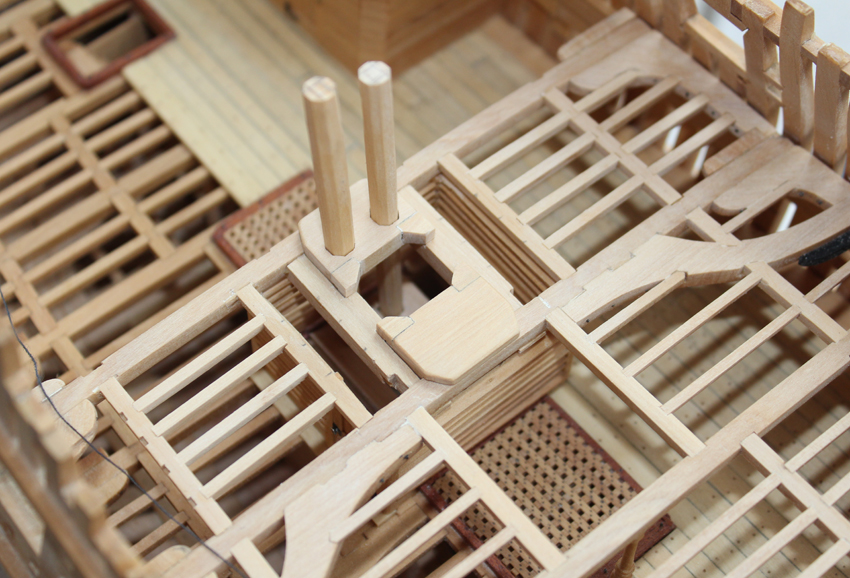
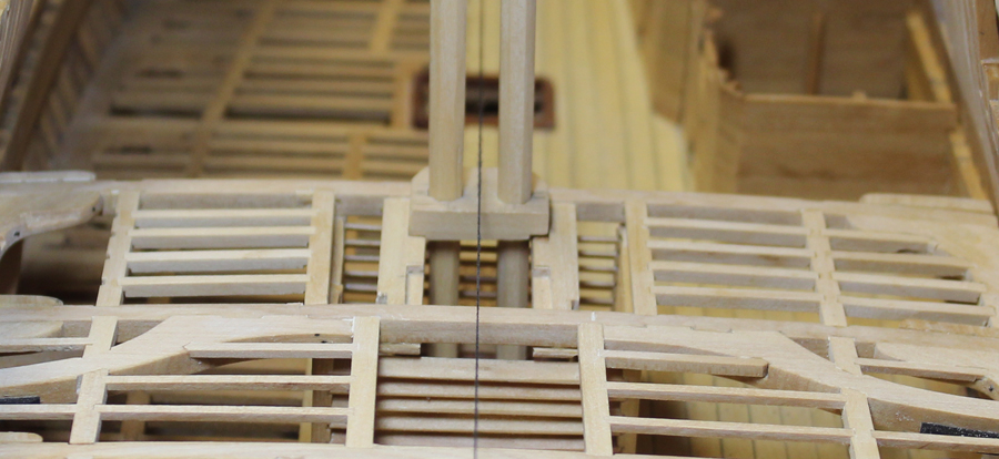
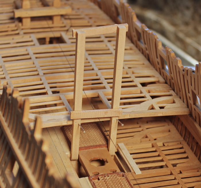
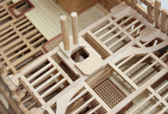
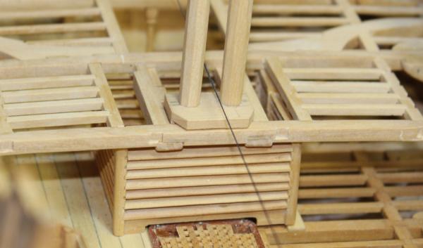
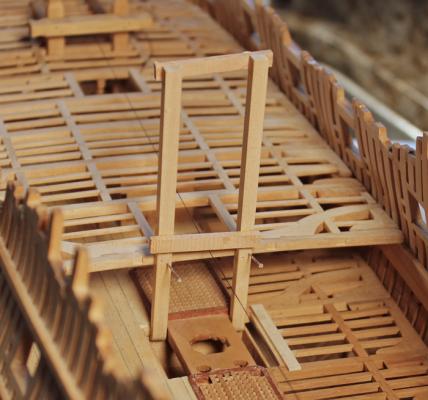
The main topsail sheet bitt pins are located within the upper well. These insert onto the aft face of the lower deck beam and there is a score for the upper deck beam. Once the well has been secured in place it will be difficult to access this area so I started them now. The pins are 9" square above the upper deck beam. Below that they taper on the aft face. They are perpendicular to the keel. Rather than make the entire bitt now and risk damage, I only made the pins up to the upper deck beam. To maintain correct alignment I glued on two temporary cross bars away from where the cross-piece and gallows will be placed. Holes were drilled through the score for the upper deck beam and into the beam. Steel pins are holding the pins in place. Holes have also been cut in the hatch cover for the main jeer bitt pins. The pictures show the bitt pins before and after the upper well was installed.

-
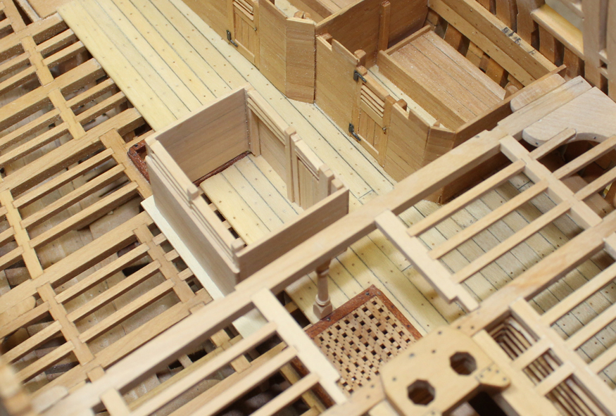
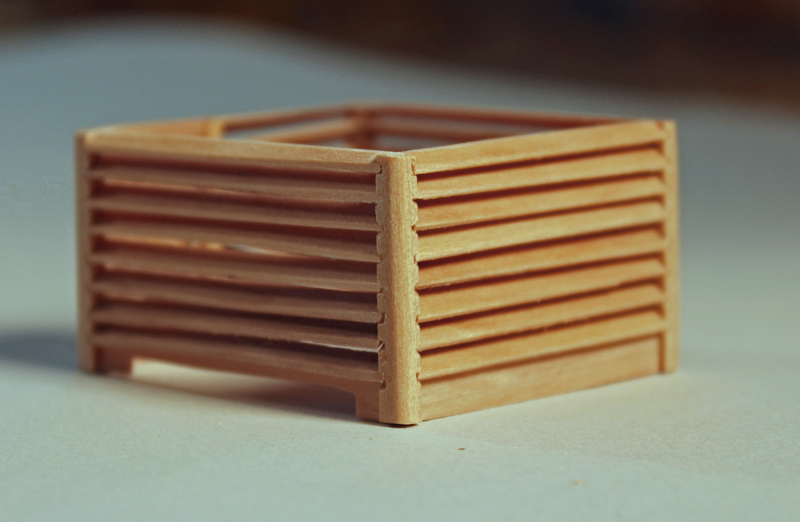
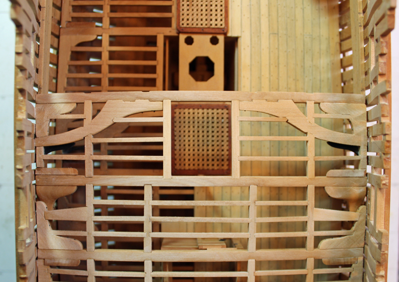
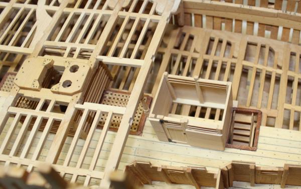
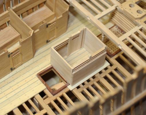
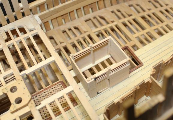
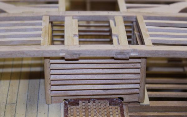
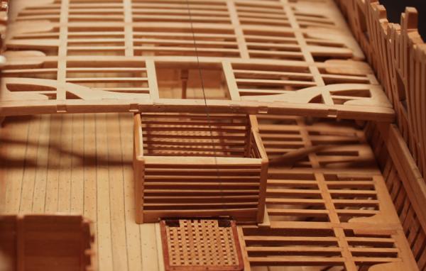
I am putting this in multiple postings because for some reason I cannot get the photos up insert properly. The stanchions are the easy part. The louvers are next. I made these over wide so they could be sanded down to the correct angle later. I started by making the two fore and aft wall assemblies (two stanchions and the louvers between them). Once they were dry, I inserted the louvers on the port side between these two walls. One of the hardest steps in fabricating the upper well is keeping the fore and aft walls exactly parallel to each other. The short wall on the starboard side was made next and finally the door was installed. The sides were sanded down to even out the louvers. There are a few slats that are not perfect but I left them in place rather than destroy the entire assembly removing them. The only ones who will know they are not quite right will be those of you reading this log. The fore and aft walls fit over the hatches and so the horizontal boards were cut back to accommodate this. A strip of planking was placed under the starboard wall. The height of the stanchions was lowered to just fit under the beams.

-
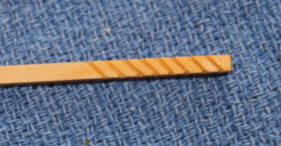
The upper well consists of three louvered walls and one wall that is partially louvered and also had a door. A total of 5 stanchions were made. Three of them had mortises for the louvers on adjoining faces and two (the ones facing the door) only had mortises on one face. There are also vertical mortises at the bottom for the horizontal boards. I was going to try making these on the Preac but after a few failed attempts went back to doing them freehand. I found it easiest to put all of the stanchions on one strip of wood.


-
Thanks John,Grant, Ben and all you who have posted likes. I had hoped to post pictures of the upper well by now but the holidays seem to be getting in the way! Two walls down... Two walls and a door to go.
-
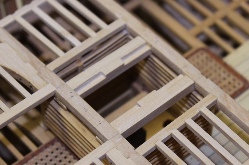
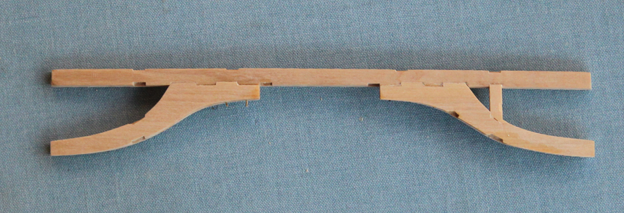
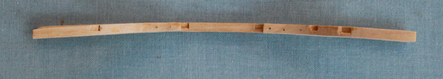
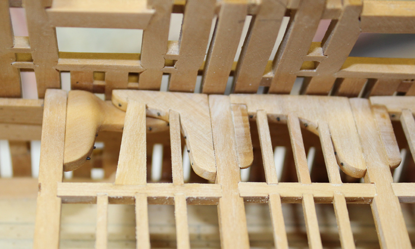
I have completed and installed the beam arms. Because of their length, these were made scale 10" thick. The deck camber was shaped added after they were fit to the beam. This beam set is just aft of the dead flat, the widest part of the ship. In order to install the assembly, only one beam arm could be glued in place off the ship. The other one was temporarily glued and then drilled for the three bolts. The glue was de-bonded with isopropanol and the bolt holes were used to align the beam arm during the rest of the assembly's fabrication. The hanging knees are now located on the aft faces of the beams. The pictures were taken before final sanding (I was running out of daylight). The next project is the upper well.


-
I used a low luster clear coat oil based finish (Testor's I think.) The ink did not bleed.
-
John, Druxey, Michael, Mark, mij, Daniel and Elia, thank you so much for your comments. And thanks for all the "Likes" as well. I hesitated answering the question about why the opposing knees exist since I wasn't sure myself. Appreciate your input, Danny. Daniel, as far as the mortises on the sail room are concerned... I did not use any type of jig. Just eye-balled the distances. When it comes to the upper well, I will figure out a better way since there will be louvers on intersecting walls. I also have some thinner saw blades with me this week and will try cutting the mortises on the Preac rather than free hand. I am reading Ed Tosti's Naiad Vol. 2 and he has a great way of making ladder stiles. It would adapt well to these pillars. All of the bolts inboard are made of 24g brass wire which is blackened in a 1:5 solution of Birchwood Casey brass blackener. In the US you can buy it from gun shops and even Walmart. I first mark the locations, then use a punch to set the hole and then drill the hole with a 76 bit. The punch prevents the drill bit from wandering. I have fallen in love with resharpened carbide bits. They are sharper and truer than HSS bits and have an end which fits my medium Dremel collet. They are also more brittle and since I drill all my holes without a drill press, they are more likely to break of there is any lateral movement during drilling. The at least two bolts going in to the frames are structural. The rest are decorative.
-
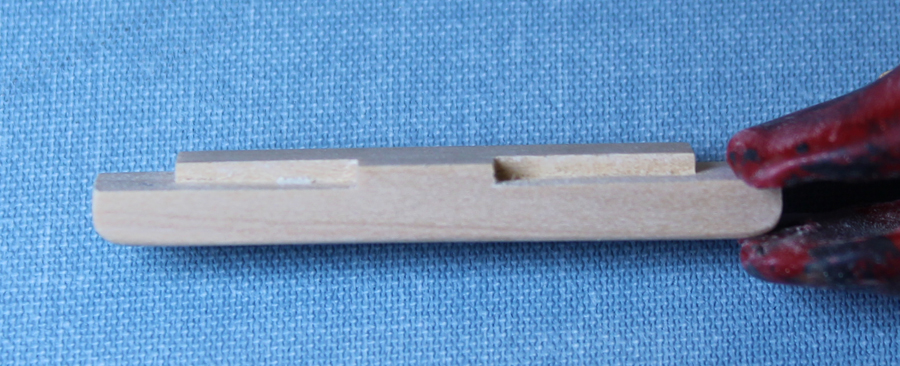
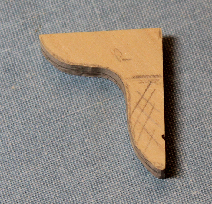
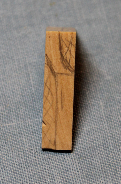
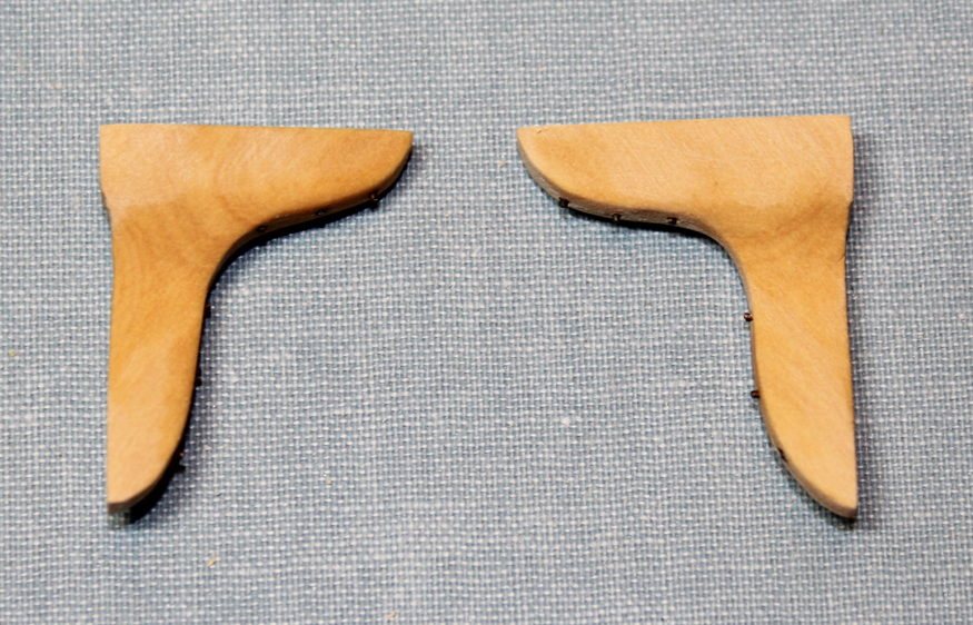
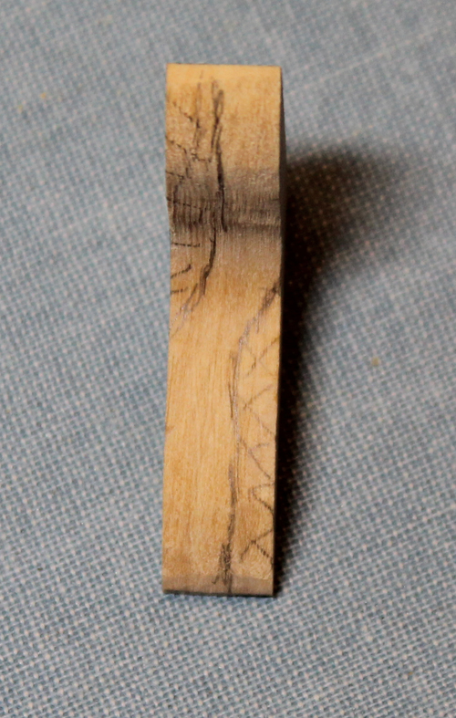
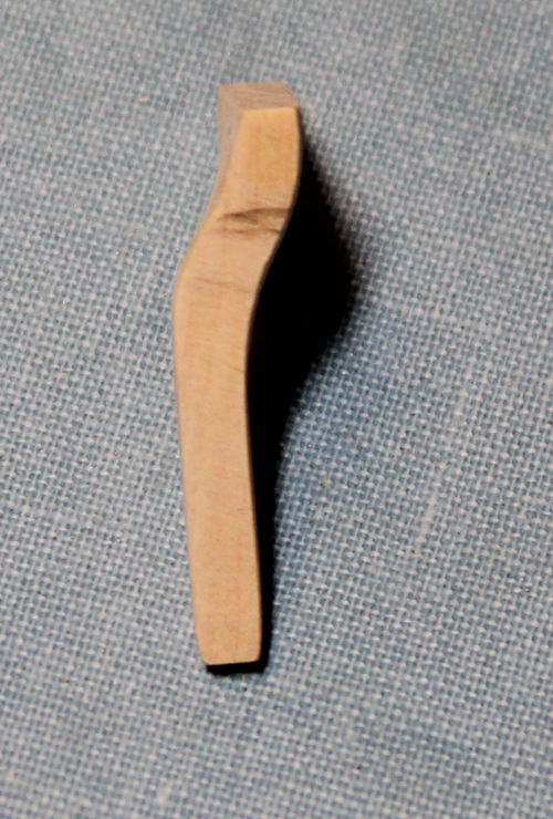
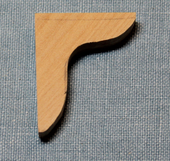
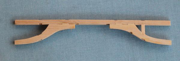
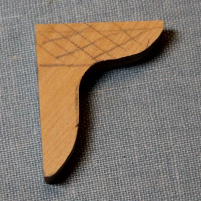
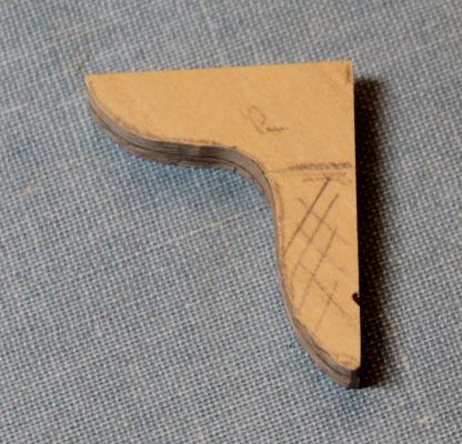
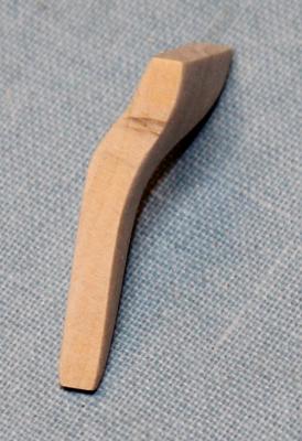
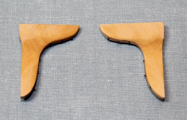
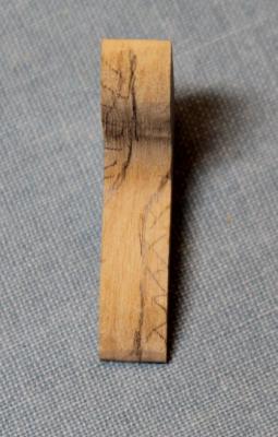
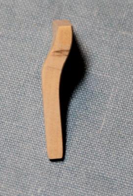
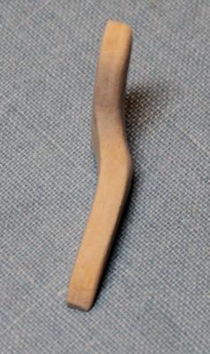
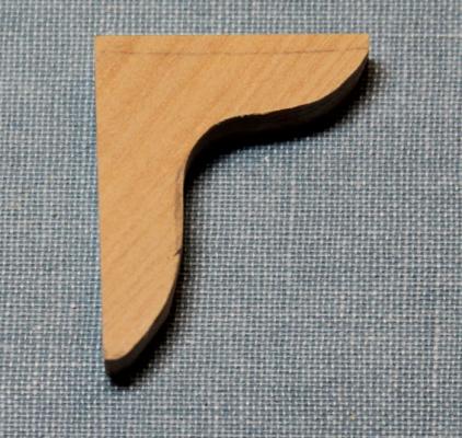
I have made and installed the opposed lodging knees. Since I did not go into any detail on their construction for the lower deck, let me demonstrate how I made them. First, I make a template of the knee and saw it out a bit oversized. The thickness of the blank is about 2.5 times the normal thickness to allow for the curvatures. I then mark on the blank the areas that will be removed. I use a combination of my Preac saw, Dremel sanding discs and sandpaper to remove the excess material. The knees are given a final shaping and the bolts are added prior to installation.

-
Just a suggestion... When making the caprail, make it very oversized. You can always make it smaller with a Dremel drum sander..
-
Everything looks fantastic. I love the jig for the timberheads. I can't imagine cutting out the timberheads neatly while still on the ship. "Cheating" seems to be the only reasonable way to go.