HOLIDAY DONATION DRIVE - SUPPORT MSW - DO YOUR PART TO KEEP THIS GREAT FORUM GOING! (83 donations so far out of 49,000 members - C'mon guys!)
×

tlevine
-
Posts
2,033 -
Joined
-
Last visited
Content Type
Profiles
Forums
Gallery
Events
Everything posted by tlevine
-
 Dan, if you put the same width spacer to either side of the centerline there should not be any distortion. If you are really worried, use CA for this step as it will not cause any swelling of the wood.
 -
Looking good. The basswood is so soft that I was able to trim the excess frame height with a single edged razor. Rotate the hull so that it is at 30-45 degrees from vertical. This makes it easier to see and gets ones fingers out of the way. Put a support under the hull and then use the razor to trim the top of the frame.
- 74 replies
-
- 1
-

-
- 18th century longboat
- model shipways
- (and 1 more)
-
Thanks, Mark. The next items to make were the hatch coamings. I chose to model them in cherry for the contrast. The gratings will be in boxwood. They are composed of four pieces (two fore and aft coamings and two athwart head ledges). The coamings have a rabbet to accept the grating. There was no rabbet on the coaming for the ladderway. On the real ship they would interlock with a tailed half-lap joint; I made a simpler half-lap joint. The head ledges curve to match the round-up of the deck. Rather than making the entire assembly off the ship and then sanding in the curvature, I glued the head ledges directly onto the beams. There is not that much round-up so pre-bending the wood was not necessary. Once they were dry I installed the coamings and cleaned up the joints. At the corners, the edges are rounded off to the deck level only, leaving a 90 degree corner from the beam to the top of the decking. Each head ledge is secured with three bolts. I did not have any brass wire with me so I dyed a bamboo treenail black to simulate the bolt. Treenails secure the coamings. I spaced them approximately every foot. The treenails are also made of cherry.

-
Thanks David, Danny and Greg. My stiff shoulders remind me why I hate treenailing. The hatch coamings have been installed. I'll try to get some photos posted tomorrow.
-
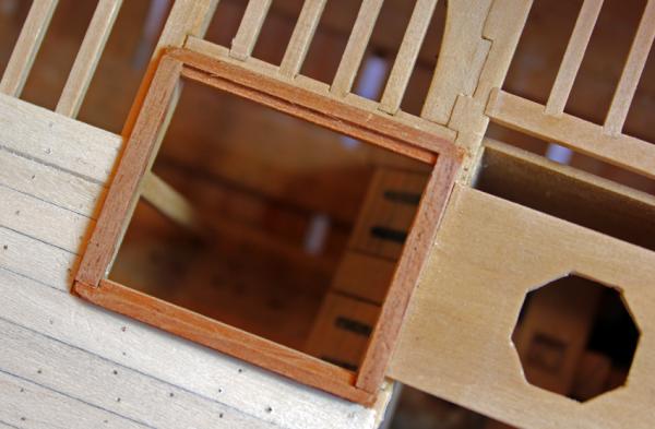
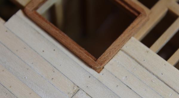
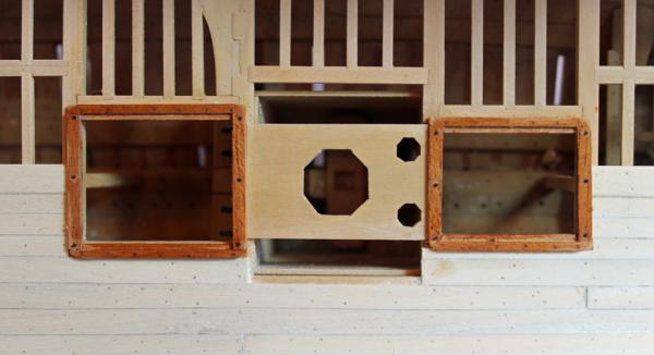
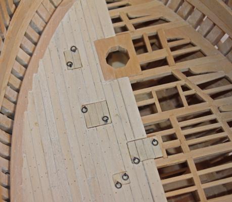
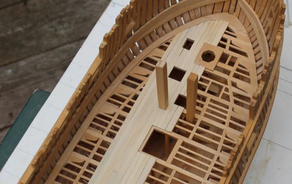
The scuttles in the fore deck are all fitted with covers. There are sills that run fore and aft on the carlings that form the scuttle framing. They can be seen in the first picture. The cover rests on top of them. These covers could either be fit to lift out (which is what I modeled) or hinged. I deliberately made the covers slightly undersized so that they would stand out from the deck planking.The ring bolts are used to pull the covers and are 3" internal diameter. They are made from blackened 24 g brass wire.They measure out correctly but look oversized to my eye. All of the eyes are oriented fore and aft.
-
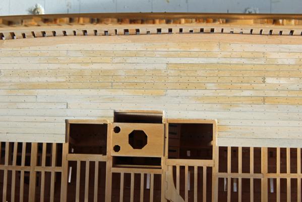
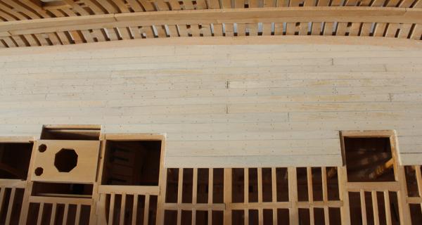
At long last the treenails have been installed. Eventually, I decided to use the standard treenail pattern of double fastenings for >11" planks, single-double for 8-11" planks and single for <8" planks. The butts are double fastened for all planks >8". I never could get the hypodermic needle thing to work at the correct scale so all the fastenings are drill size 77 or scale 3/4". I prefer to insert the treenails dry with a tight fit rather than more loosely with glue to secure them. The deck planking appears mottled in the pictures because I wet it to show off the treenail pattern. It started to dry before I could get the pictures taken. In the last picture the wood has almost dried out and the treenails almost disappear. This was a lot of tedious work for something that will never be seen in the completed model.
-
Looking great. Why tear your hair out getting a halfway decent result with the basswood when it is so easy to get a beautiful result with a hardwood such as boxwood?
-
The floorboards sit on the ribs (frames) of the boat. In order for them to be level, the ribs would have to be built up to support the floorboards. Additionally, David Antscherl, in his design of the cutter for the Swan class, also shows the floorboards as running with the curvature of the hull. And if the ship-model-god says thats how they go...
-
Grant, I am trying very hard to come up with a clever Tolkien-esque response...and failing miserably! But by the time the upper deck and the hull planking is completed, eleventy-one gazillion is looking good.
-
Thanks, John. Twenty eight meters? Thanks for the good news, Danny.
-
Yes, Dan, you are overthinking this. The key is where the exterior bulkhead meets the rabbet. You are going to be sanding down the internal keel and thinning the remaining part of the bulkheads once the central section has been removed anyway. One suggestion...as much as possible keep the keel assembly in the building board to prevent racking. Looks good so far.
-
Thanks, Druxey and Grant. After looking at a few other builds and how the treenail pattern was handled, I have decided to put the same fasteners at the beams as at the ledges. It looked like something was missing when I put in nothing and the hypo technique just wasn't working for me. Now it is on to drilling a gazillion holes and making yards of treenail stock.
-
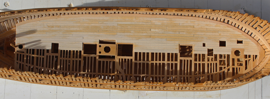
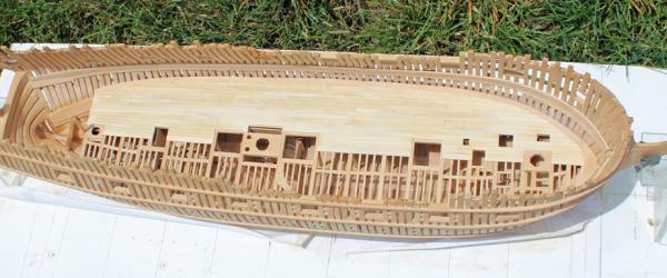
The rest of the lower deck planking has been installed. I have removed the bit pins to prevent them from getting damaged. According to TFFM, joggled planks were not commonly used in this time period. David's suggested layout shows them, however, so I used them in four strakes at the bow. I guess I just like the way they look. The last three strakes aft and the last two strakes fore are dropped to prevent the end of the plank from being too narrow. I have not decided what I am going to do for fastenings. Deck nails were used to fasten the planks to the beams. They were countersunk so wood plugs could be inserted above them. I have tried unsuccessfully to show these plugs with a hypodermic needle. To remain in scale, a 25 gauge needle is required. I found that this bent after only a few uses. Seven-eighths inch treenails and doualls were used at the ledges and butts respectively. At this point I am leaning towards installing the treenails and doualls and skipping the plugs, as they would barely be seen anyway.
-
Chuck, I hope the Chicago contingent will catch up with you guys soon. I know of two complete models. Maybe the fleet can form an armada at the NRG Conference in October.
- 175 replies
-
- 1
-
-
- 18th century longboat
- model shipways
- (and 1 more)
-
Druxey, right you are. Thank you Karl for your kind comment. I chose the holly because I did not like the effect of everything being the same color. One the finish is applied, the color contrast between the two woods will be less. Also, once the bulkheads are installed, much of the deck planking will be obscured anyway.
-
Ben, Tom and Brian, thank you. Although I wouldn't exactly say it is moving along quickly. Next month will mark the two year anniversary of beginning construction.
-
Welcome aboard. Soon there will be a fleet of longboats.
-
Gorgeous work as always, Remco. Are you planning on planking the lower deck? I did and then discovered I could not remove the riding bitt pin. I had to remove the deck planking and reshape the lower part of the pin to allow it to be reinserted later. Danny mentioned that encountered the same problem.
-
Thanks, Kevin. Danny, once I discovered this I toyed with completely finishing and mounting the pin but decided that it would get too banged up while finishing the lower deck and building the upper.
-
Chris, David, thanks. Druxey, great idea. It really illustrates how one must think ten steps ahead with every piece that is built.
-
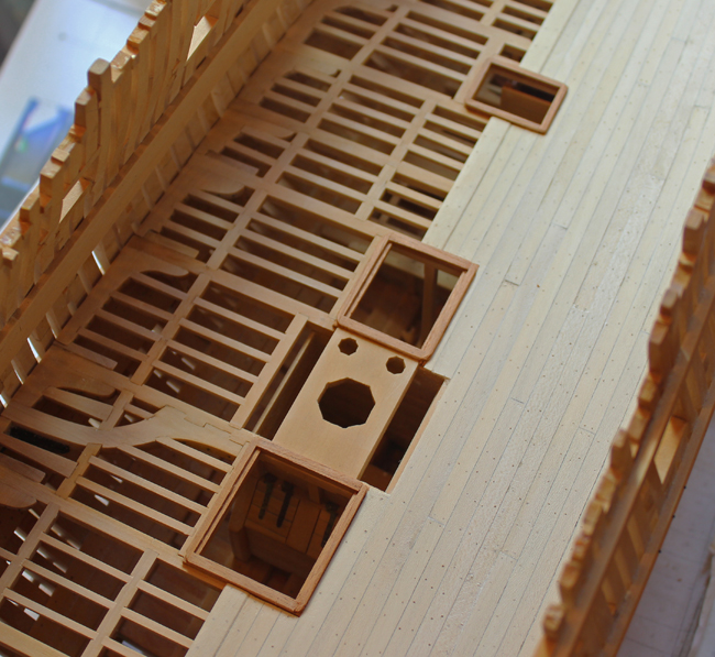
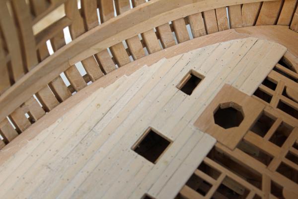
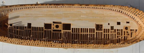
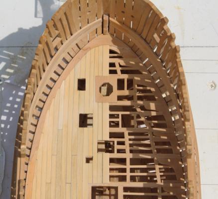
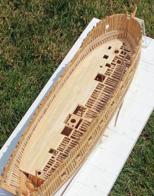
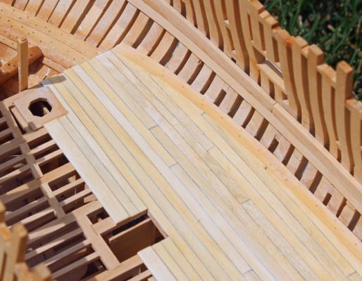
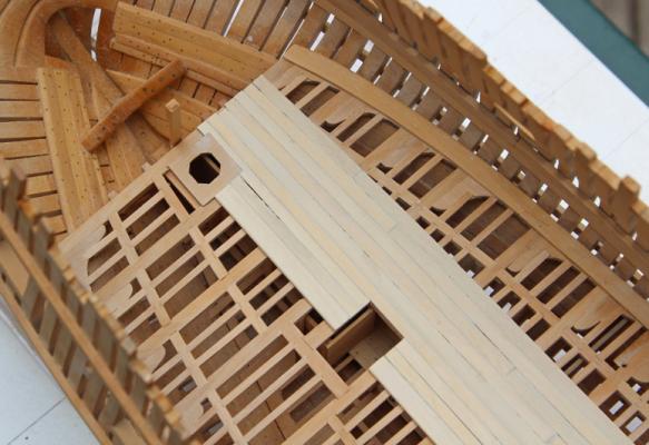
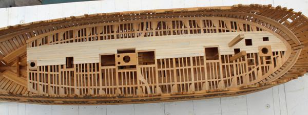
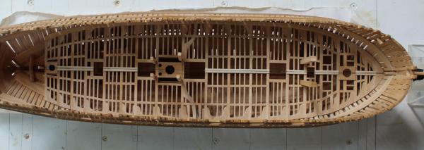
I have progressed a little with the deck planking. This is 2" thick, in contrast with the king plank which is 3" thick. There is a mild taper in the planks towards the bow and (more noticeably) the stern. Not all of the planks are the same width at midships. In particular, the planks between the outboard edge of the hatchways and the king plank are narrower. Caulking is represented by pencil. The planking extends all the way to the beam edges for the scuttles but is recessed 5" for the hatchways to accommodate the hatch covers. The riding bitts are temporarily installed to allow the deck planking to abut the timber. At this point I decided to remove the bit and discovered that it would not come out. The bitt is notched to fit into the fore platform and lower deck beam. Not a problem when the framing is left exposed; big problem when the deck planking has been installed. The solution was to remove the deck planking around the bitt and taper the fore edge down towards the lower platform, rather than having a notch for the lower deck beam. The starboard bitt will be left with the notch intact.
-
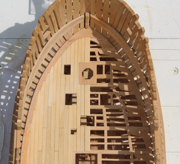
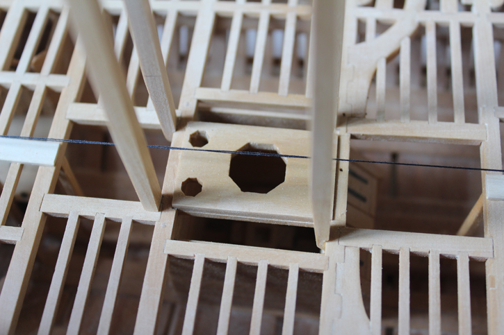
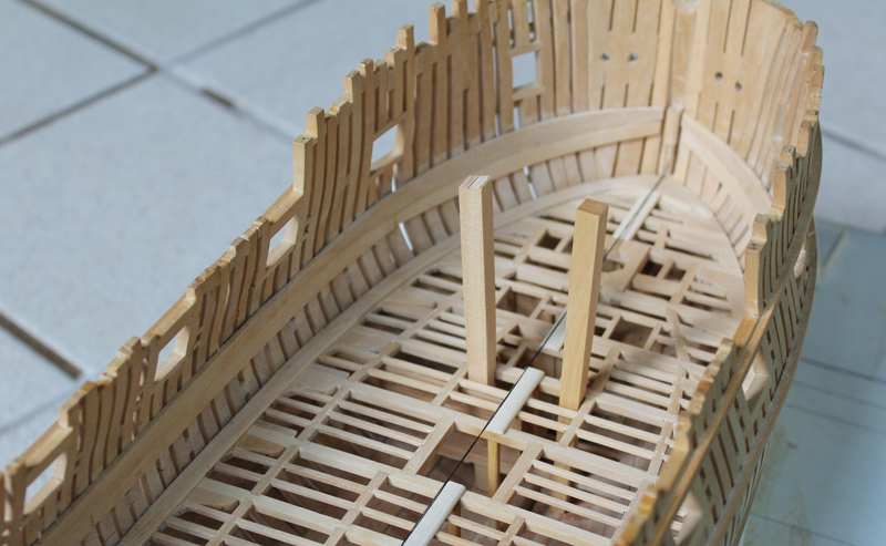
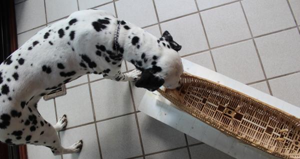
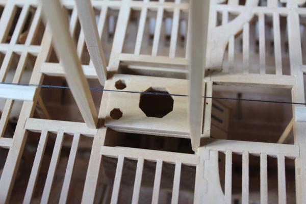
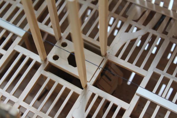
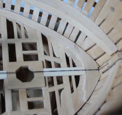
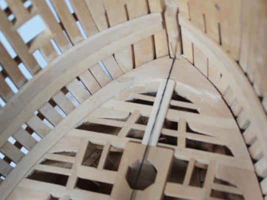
I put in the centerline or king plank next. This plank is 3" thick and the lateral edges are beveled. My deck planking will be holly with one edge and end highlighted with pencil so the seams are more apparent. The hardest part of deck planking is determining the centerline. I drilled a hole in the midline of the stemson and inserted a pin into the hole. A doubled thread then is secured to the pin and to the #19 pillar to determine the midline. The thread is evident in the pictures. The pins for the riding bitt, main topsail sheet bitt and the main jeer bitt were temporarily installed. The riding bitt extends all the way to the thickstuff over the floorhead. The other bitts end at the lower deck beams. These are 9" square but have an aft taper below the upper deck. The dimensions at the lower deck beam are 6"d x 9"w. The foot is rounded over. These are shown in TFFM as being bolted flush to the aft side of beams 11 and 12. The draughts for Atalanta show that they are mortised into the beams and that the jeer bitt is also mortised into the after hatch framing. These are (theoretically) bolted to the beams. In the pictures I made no attempt to check for plumb, as these were only temporarily fastened. During the construction of the lower deck framing, I did not think far enough ahead. I should have made these bitts and drilled the bolt holes as assemblies 11 and 12 were made. At this point, it would be next to impossible to put those holes in. Of course, while I am taking pictures, Sadie decided that she was not getting enough attention. It looks like she is taking a bite out of the stern. In reality, she loves masking tape and the midline thread is secured with some (which she is trying to remove). Since we almost lost her to urosepsis last week (a really bad kidney infection that gave her blood poisoning in normal people talk), I guess I can tolerate some of her idiosyncrasies. But if she ate a piece of wood...
-
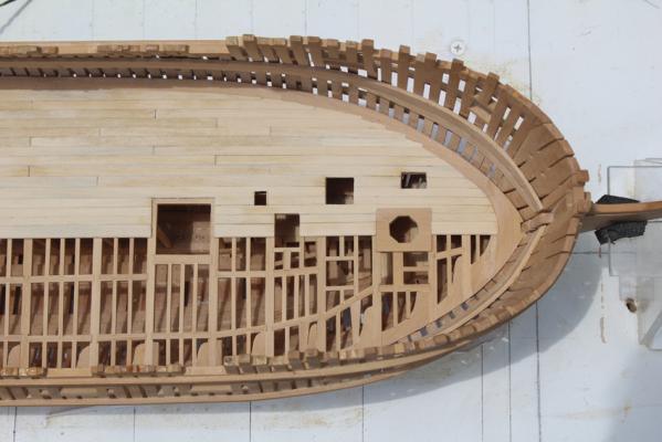
I have accomplished a lot of little things since the last posting. Some of these included mock-up of internal planking to decide how I want to procede. In order to show off the framing of the lower deck, I will leave the starboard deck completely bare. (Yes I know it will be barely visible regardless.) I will put in the waterway on the port side but will not install the spirketting on either side. Internal bulkeeads will be installed on the port side only. The waterways are 3" planks that taper medially to 2" to match the thickness of the deck planking. They are 12" wide. There is also a lateral bevel to mate with the bevel of the spirketting. I could not get a good picture to demonstrate this. The bevels were scraped in with a razor blade and then sanded. Once I had fabricated the foremost waterway plank and its scarf, I cut the scarf in to the eking piece on the port side and copied it on to the starboard side. I could not find a trunnelling diagram either in TFFM or in the various build logs for the waterways so I decided to put two trunnels into each beam and a single trunnel between frames and at the scarf joints. The trunnels are decorative.

-
You will sand the keel down to match the thickness of the frames. Actually, the thickness of the frames left after removing the center section of the bulkhead is a little too thick and needs to be taken down a little as well. If you look at page 1 of my build you will see a series of photos depicting this. One shows the frames and keel without fairing. The next shows the beginning of the keel height being taken down. And the last one is the completed keel and framing. Look at the relative thickness of the frames at the sheer in the first and last picture.
-
Much nicer. That slight difference you will be able to make up in the next strake.