


Hubac's Historian
-
Posts
3,243 -
Joined
-
Last visited
Content Type
Profiles
Forums
Gallery
Events
Posts posted by Hubac's Historian
-
-
Wow - these are a tremendous improvement over earlier efforts, Eric! I like how you did the scale detailing.
-
David, I am surprised every day. Life moves real fast with teens today. All good, though.
-
Your correction at the cutwater as something I was wondering about. It would not have detracted from the model, if you had left it as-is, but it is a nice improvement, nonetheless.
Thank you for posting such good chimney pics. They are really helpful. While you may feel that you aren’t going too overboard on the details, I think you have added so much to this kit, and corrected quite a number of its fundamental flaws.
So much with sailing ships has to do with the lines, and the lines of your ship ring so true!
-
2 hours ago, Nek0 said:
I love this sentence: "we are given to know our chidren during childhood only for a couple of years, then we know them as adults for the rest of our lives." These few years when they need us are so precious and important that we have to do as much as we can during this period of time. Sport, games, educationals, time together, help them with their lives... With our jobs it's not always an easy thing, and modeling sure is not a priority compared to that.
I also hope your ankle will be alright !
Concerning L'Ambitieux, I sat them down a few days ago. I intended to make a post when all the gun ports would be completed but I just took a couple of photos I can show you.
")
So true, about Children! I will look on your log for the pics - much appreciated!
-
That’s a nice creative solution to enhancing the 3-D appearance of the dolphins.
-
From what I know about cataract surgery, Bill, it should help model-making a ton! This is one if the more low-risk, high reward procedures.
-
Hi Kevin! Yes, I will be borrowing a knee walker from my work partner, who also recently had bone spurs removed from his ankle. Definite game changers.
And, yes, as I was making chimneys last night, I was reminded just how much I love the process of design and fabrication. I can totally lose myself in that for hours at a time!
-
Thank you, Marc! I just visited your Ambiteaux log because I needed to clarify a few details, regarding the galley chimneys.
I will have a small update on this project in the very near future. I’ve been puttering around with the f’ocsle deck - engraving plank seams, fabricating chimneys and the capstan. Soon, I’ll design the break rail filigree and the belfry.
Unfortunately, the school year is about to start which means I will, again, become completely engrossed with coaching basketball for one more season. We are also in the process of getting my daughter into University and my son into high-school. So, yeah, family first for sure!
Necessarily, not a substantial amount will happen on this build until around April of next year. I am planning a major left foot and ankle surgery for that time, which will mean three months of recovery. I plan to invest a lot of energy into the project, at that time. In the meantime, I will do what I can reasonably do.
As always, thank you to all for maintaining your interest in this project. It is all very much appreciated!
-
-
-
A truly stunning piece of work, Siggi! A museum should only be so lucky as to have her in their collection.
- Keith Black and Siggi52
-
 2
2
-
I can see the appeal of having the trophies stay in-line with the run of the ports, but I am thinking that these ornaments would not cross the wales on the aft two ports.
On the DR of 1680, as the wales are cut by the ports, albeit not to the same degree, the ornaments remain on the planking between wales:
- Archi, EricWiberg and GrandpaPhil
-
3
-
That is definitely a dream of a work space, Chuck! I am sure you could fill that whole space with WIP, when you’re fully up and going 😁.
As ever, the progress on the project is inspiring, and above all - informative.
- cotrecerf, Chuck, Ryland Craze and 1 other
-
4
-
-
It’s been a while since I last checked-in, here, but you are certainly making a Capital job of it all. Really well, done!
-
I’m at a loss for words, Mark, but you know how I feel about the project. Just awesome!
- Ryland Craze and druxey
-
2
-
So, your first question caused me to focus on the fact that you have, in many cases, metal rods cris-crossing behind the shields. As they are, if you simply tried to glue the trophies to the hull, they would invariably pivot unevenly on the lowest placed element. This would be a weak bond. My solution to this problem is essentially what you are proposing; behind and within the footprint of the shields, I would glue styrene pads in 2-3 places that then become my glue points to the hull. This ensures a strong bond, and that your shield ornaments would sit evenly on the hull.
One thing you don’t want would be to have cris-crossed cannon barrels, for example, hanging freely above the hull planking. Portions of ornaments, such as these, should also be supported from behind and firmly attached to the hull.
I also agree with you that you will want to glue down the upper port surrounds and frieze elements before painting. You could wait to affix these ornaments until after painting the upper works, however, it would be advise-able to scrape away a small paint patch for glue.
For small things like fleur-de-lis, this is difficult to achieve within the small footprint of such an ornament. It is far easier to become practiced at detail painting, in place. Glue a small field of fleurs to a spare hull part and practice. I have found that the best way to achieve a sense of depth on the painted ornament is to continually adjust the angle of approach, so that I can always see exactly where the tip of my brush is.
When looking at my model, for example, please keep in-mind that while I AM very good at this kind of detail painting - What you are looking at is the end result of numerous rounds of retouching. It looks very close to perfect because I kept revisiting this and that flaw over a long period of time.
As for extending the bronzing protocol to the ornament and port surrounds above the main deck, this is something I would personally avoid. While it is absolutely true that gold leaf budgets were more closely adhered to in the 1680s and 90s, these first two capital ships of the new Navy, SR and the RL, were always intended to be spectacular realizations of the Monarch’s power and influence.
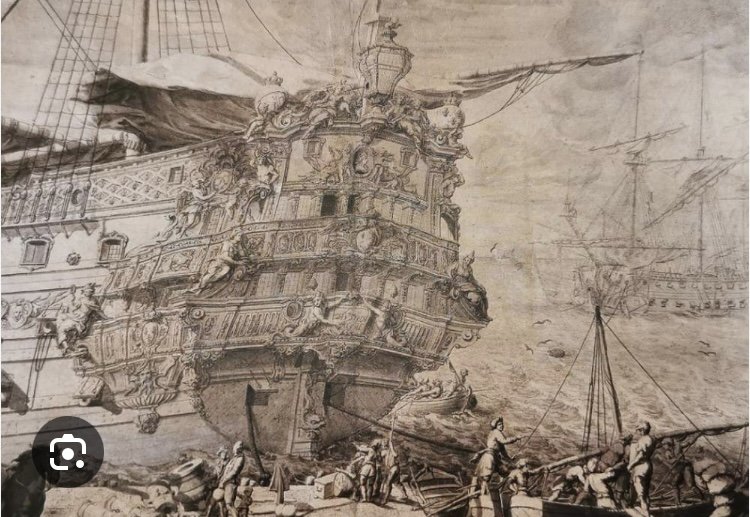
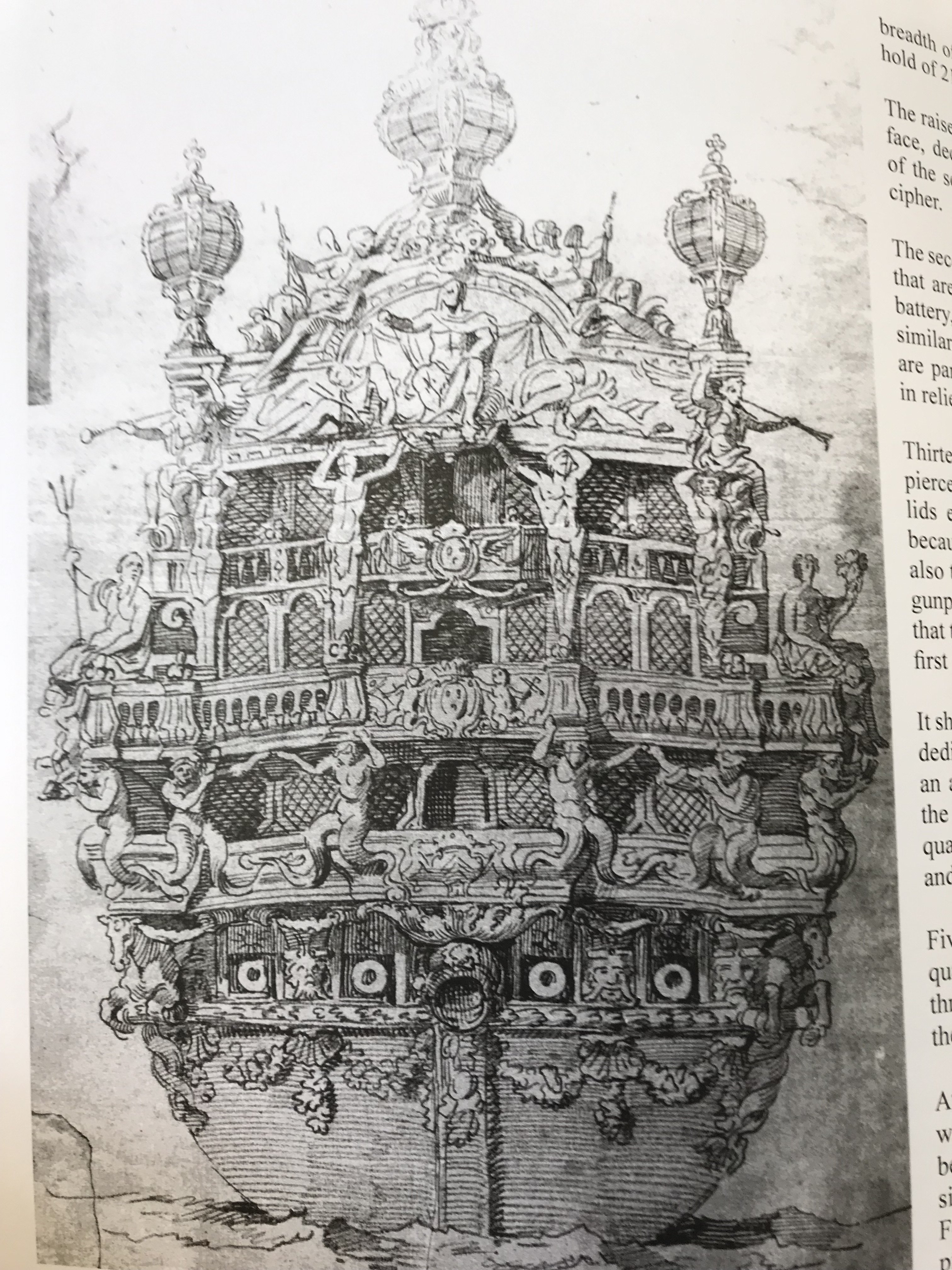
Just as Versailles is blanketed in gold leaf, I think it likely that gold was used much more liberally on the first launchings of these two iconic ships. I think that, largely, because Hyatt’s description of the first RL in 1677, just before her first refit, paints a fairly vivid picture of her ornamental works. I have translated and tried to clarify some of the ship nomenclature, throughout:
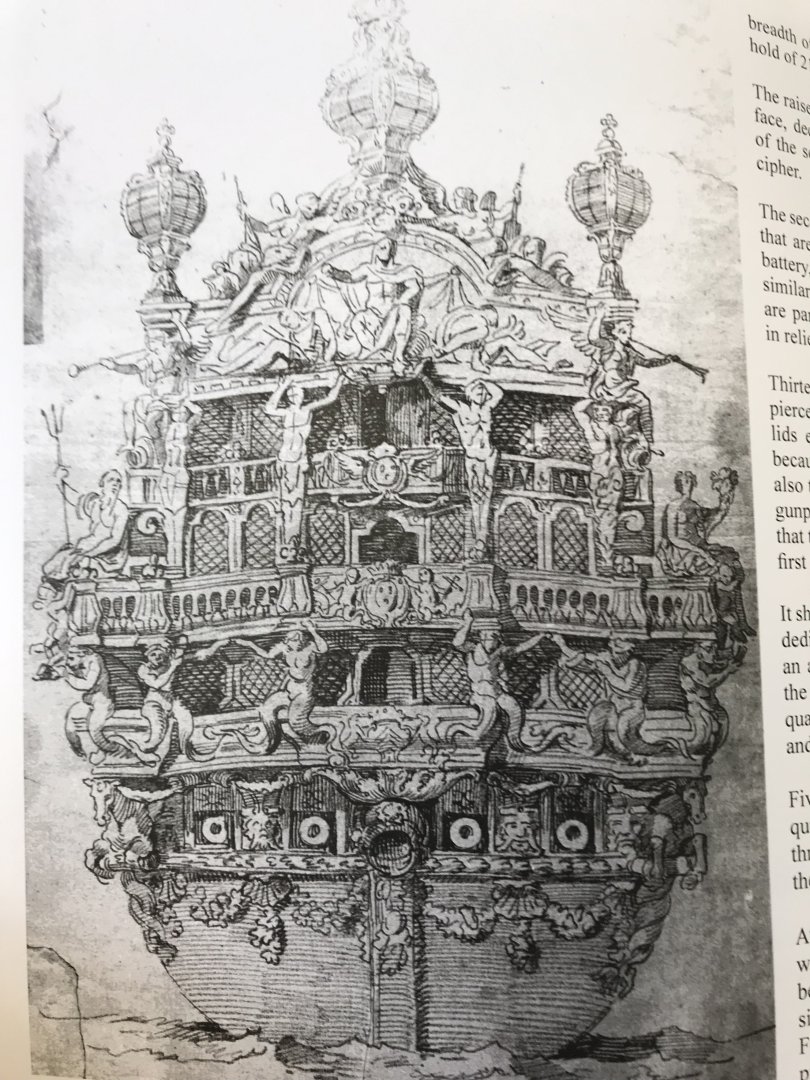
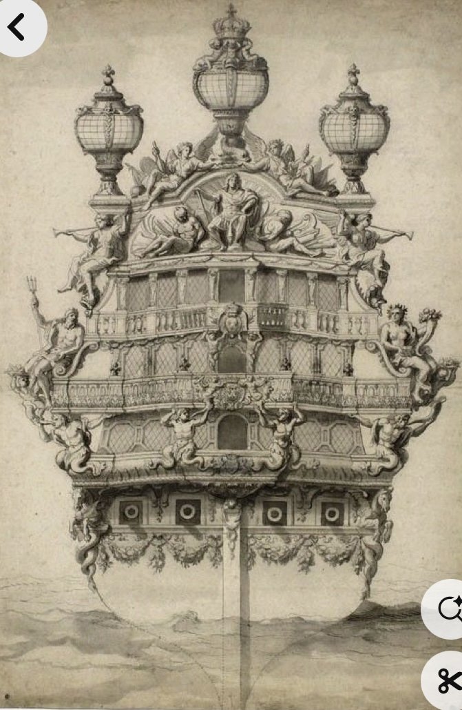
“The smooth dourdy [lower transom] is enriched outside laurel leaves with shells seashell on it, all of ore has perfection.
Over there is a marine horse at each coast [side of the lower transom] and four large consoles that support the first baterie [lower stern balcony], above which there is a very beautiful cul de feu lamp [concealing the rudder head and stern post].The first gallery, at the height of support is all dotted with fleurs-de-lys d'oreen [in gold], on which are affixed four sirens that serve as a support for the second gallery, and costez [along the side galleries] three tritons and two consoles with a frieze that runs all around, where are the arms of Monseigneur le Duc de Beaufort, supported also by two tritons holding an anchor with one hand; on the starboard side Neptune and Thetys on the left, with a babe at their feet, present[ing] in the divinity of the riches of the earth and the sea, which they then present to the figure of the king, who is in his throne of justice above the third gallery in relief and gold. as well as the whole stern, with a slave of each side and a cornice of gold which reigns all along the ship [sheer rail all in gold?], with trophies joining the said divinities.
On each corner, from above, there is a renomee [fame] each holding a trumpet.
On the second cornice at the coronation, which has the same effect as the other, are two affixed figures holding in their hands a crown of laurel on the head of the King, of one side, and on the other an olive branch.On the third floor [quarter deck level] there is a balcony, two feet high, where the king's arms are in a medal, on which there are four capitals, or four half-bodied figures, all of them representing the four parts of the world.
All portals of ports [gunport lids] are adorned with fleurs-de-lis, figures of the King, lyres, and suns. All between the wales [from the quarter deck level to the sheer railing] there is a frieze in gold which reigns all along the ship, of fleurs-de-lis, also of gold.
Between the ports of the second baterie there are trophies of the navy, all of them between lasses of peles [?indescipherable?] and anchors of the same.
Those [ports] of the third gundeck are adorned with a frame of foliage with griffins on the sides, all of gold in perfection.
At the highest wale [beneath the sheer rail at the poop deck level] there are consoles of space in space, with festoons between two, all in gold.The sides of the vessel with smooth are enriched with fleurs-de-lys golden with molures[?].
The whole mirror, in other words, the guardianship of the vessel is blue in color with golden fleur-de-lis [the stern/tafferal, I suppose].THE BOW
At the bow of the vessel there are two great escolats, two half-wives, whose bottom ends in foliage running along the precients.
All precients of the bow are the same, with consoles from below the bows and florets gild space to space.The figurehead is a renowne [fame] holding the king's arms, with a little triton underneath, which has it to wear them, all of which is excellent.
The crane carriers [cathead supports] are two big tritons of gold. At the face of the castle of Prou [beakhead bulkhead] there are two children in low relief of gold who carry one a laurel and the other a palm, are an escort or are the arms of the King. The whole bow is adorned, even the herpes [head rails] of fleur-de-lis and the figures of the King of the Golden Crown in perfection.- GrandpaPhil, Mr Whippy, Archi and 1 other
-
4
-
Okay, now you are getting to the fun part - bringing all of this to life!
For your same stated reasons, I would steer away from bright gold or yellow ocher. The admiralty style model of the SP chose yellow ocher, but this can be a bit much:
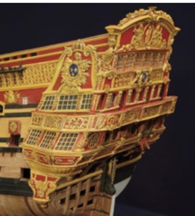
You could go the route of John Ott, and use a light sand color as a base, and then overlay that with a darker brown, translucent acrylic wash that will get into all the crevices and give the TsOW some depth.
Personally, I would avoid anything too polychrome. You don’t want the ship to look like the U.N.
However, if this were my model to paint, I would probably take one of the following approaches.
First approach:
Over a primer base (flat black), I would spray a uniform, matte acrylic dark bronze (almost black, but still brownish). Over that, I would selectively dry-brush either a bright bronze metallic acrylic, or I’d dry brush bright metallic bronze powders (later sprayed with a matte, clear fixative). These types of powders are available through the same outlets that supply railroad modelers. The idea is to merely catch the highlights, here and there; part of a shield edge, here, a spear shaft there, etc. You are trying to avoid any sense of gloppiness in the dry-brushing. There are endless dry-brushing tutorials on YT.
The advantages of this approach are several. If there are any particular aspects of any given trophy that you wish to de-emphasize, then they will fade into the background of the darker base color. Overall, the TOW will show a strong contrasting silhouette against whatever color you choose to paint the planking of the hull. The bright bronze highlights draw attention to where you want it most.
Second Approach:
This is a slightly more advanced (read: more work) version of the above, which should yield an even greater sense of depth.
Over a black primer, airbrush a matte acrylic dark brown that is not nearly as dark as the black bronze, but not too light either. Over that I would spray a clear acrylic dark brown wash (matte) that will get into all of the crevices. Finally, I’d dry-brush with either bright bronze acrylic paint or powders.
As for prepping your hull to paint, here is what I would do - so far as the TsOW are concerned. First, clean both hull halves in light, soapy water. Once dry, I would place a patch of blue paiters’ masking tape, in each TOW position. Rub the tape down firmly with the pad of your finger. Sharpen a #2 pencil to a WICKED point. Holding each TOW in-place with light finger pressure, lightly trace its outline onto the blue tape. Be sure to stay as close to the border of the TOW as possible (the reason for that wicked point). For the trophies where there is a profusion of thin shafts, and flag staffs protruding outside of the shields, I would not concern myself with masking outside of the shield.
Next, use a razor sharp EXACTO (#11) to cut a heavy 1/32” inside those lines. Doing so, will ensure that you have a good-sized glue area (mostly the shield area, but also cannon barrels, flags, etc), and that the shield will overlay the planking color completely. Finally, pull away the outer tape, and your hull is ready for primer and paint.
I would also spare myself the difficulty of painting the TsOW on the model. I would simply follow one of the above paint protocols, off-model, and then you can attach them and have perfect borders. As you noted before, this also enables you to distress wash your hull planking without the encumbrance of the TsOW.
- Archi, Ryland Craze, GrandpaPhil and 2 others
-
5
-
Better and better, for sure!
-
Those guns are pretty fabulous! And, agreed on use of mixed-media to get the results you’re after. Awesome trophy!
-
-
With every effort, your trophies get better and better, Eric. That was a clever idea to use the kit cannon barrels. It really adds a nice bit of detail with the fleur-de-lis that adorn the barrels.
- EricWiberg and popeye2sea
-
2
-
Siggi,
In my estimation, you can count yourself among the very best in the ship-modeling community. There is, simultaneously, precision of craft and the hand of the maker. Your tiller is a real treat!
Best,
M
-
Love it! Looks awesome, Eric!

Amerigo Vespucci by Bill97 - OcCre - 1/100
in - Kit build logs for subjects built from 1901 - Present Day
Posted
Nice progress on your latest build, here, Bill! I really like the herringbone decks - they look really cool. Also, love the GH project with your grandson!