


Hubac's Historian
-
Posts
3,292 -
Joined
-
Last visited
Content Type
Profiles
Forums
Gallery
Events
Posts posted by Hubac's Historian
-
-
-
-
Perseverance. Camaraderie. These are the ties that bind us to each other, and to our projects in-hand. As always, many thanks to all who continue to persevere here.
Small update. They’re all small these days, but chipping away.
I will say that it is always remarkable to me that no matter how scrupulously I draw something, and use straight edges to scribe the lines into plastic, while also accounting for the half-width of the blade-to-point (and the half-width of the drawn line) - there are always WILD discrepancies from the drawings, in the cut parts.
It is essential, IMO, to make the actual parts fit the initial drawing, because the pattern/drawing is based directly on the actual deck camber; minuscule discrepancies in angle-to-post will create gaps between panel and rail that are much more difficult to remedy, given my sub-assembly approach to building these breast rails.
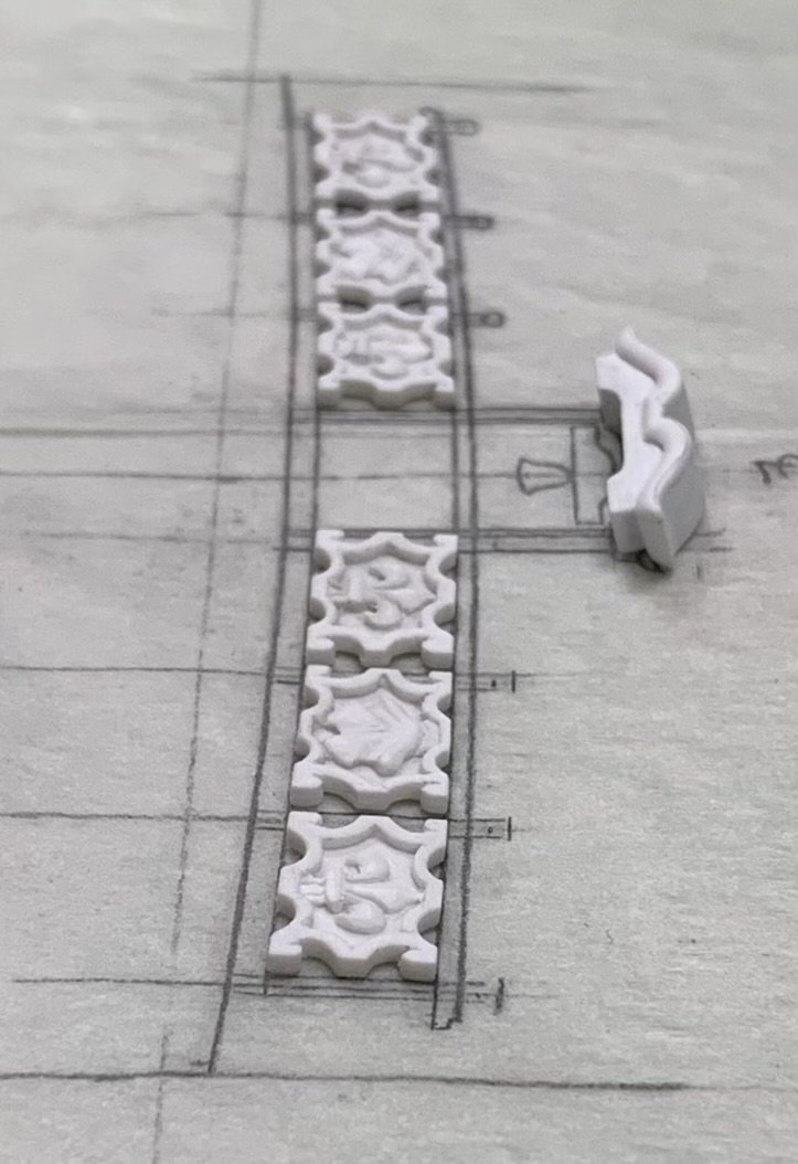
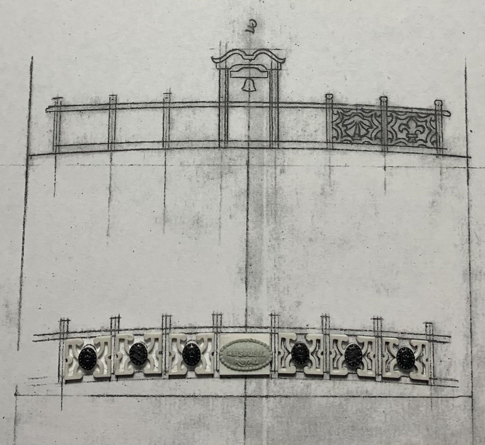
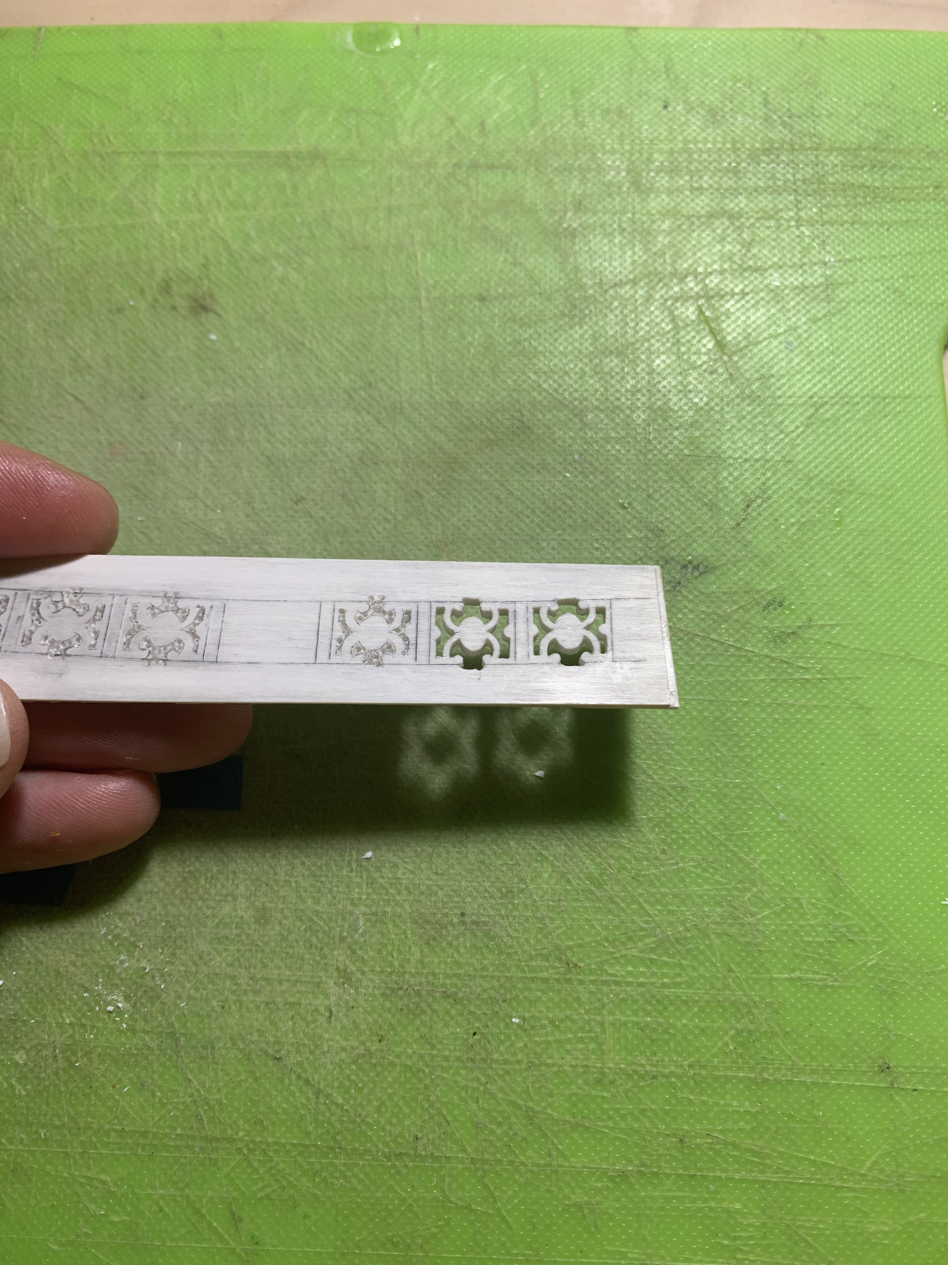
Here are my panels laid as carefully over the drawing as I can, after they’ve been parted on the lines with a razor-sharp chisel:
One has to account for the shortcomings of phone-photography - which does not provide a truly flattened perspective in close range, however, it is evident in the picture above that there are overlaps, and angle-to-post inconsistencies that would make a final glue-up far less than ideal.
My advice to anyone that reads this will be to trust the quality of the initial pattern that you make. Base all of your geometry on that. Shape your parts as closely as you can. You will have FEWER surprises on assembly.
Part of what is happening here is that I am paring to a line with a really sharp chisel through soft plastic that is less than 1/16” thick. I am squaring that chisel intuitively by eye. I am careful to always leave less than 1/32” for my final paring cut to the line. And. And, yet. The chisel will still drift to an out-of-square cut.
I say all of this to say, that fitting these small panels to a drawing:

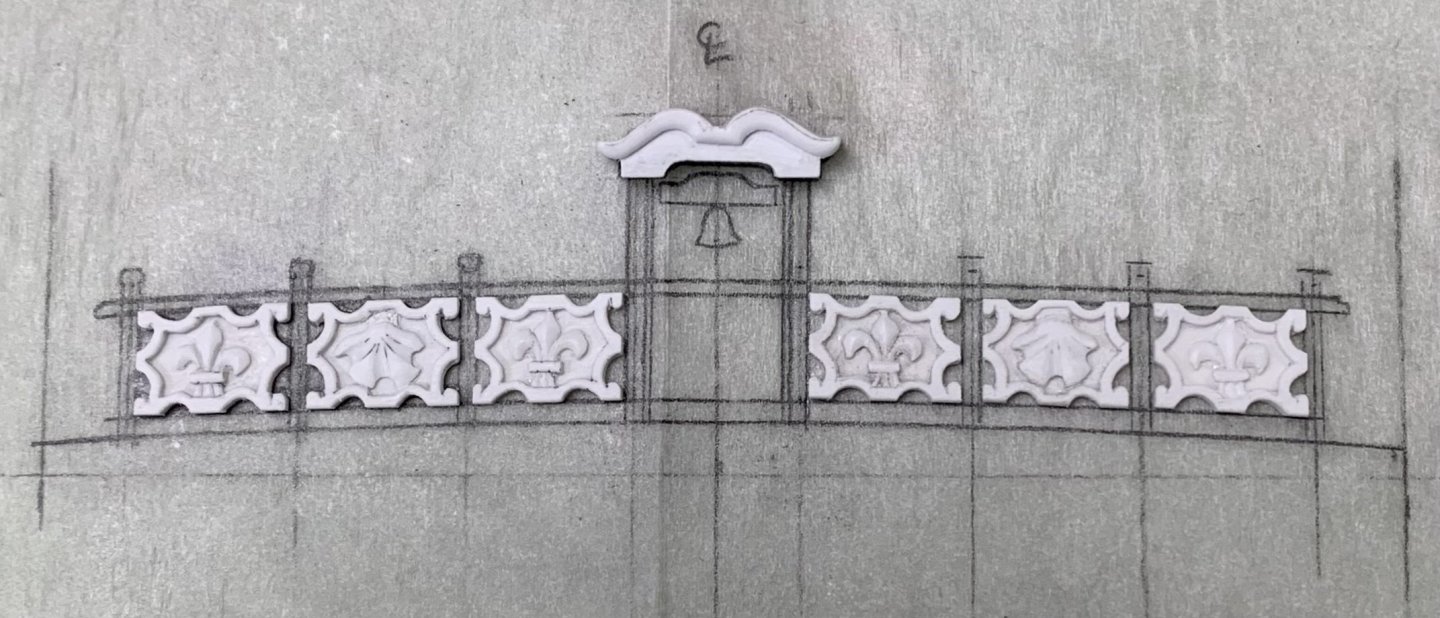
is a process of consolidation; of checking and re-checking against the drawing; a little from the lower left corner; a little from the top right. Oh, and the central panel does require some actual camber along the top and bottom surfaces. A very little here, and a very little there, and eventually I have arrived at a reasonable bet for sub-assembly:
I will note that the central “Soleil Royal” badge is, in actuality, 1/64” off center. I point it out only to highlight that this is what the eye can perceive. In this instance, it is a consequence of process and bonding.
I’m using C/A to bond BONDO to plastic. The window for placement is limited. I managed to get the top/bottom spacing right. In the end, after all is said and painted, and posts are in-place - the discrepancy will hardly be noticeable. There is too much else for the eye to focus on for it to matter.
Next, I will make the knee/post supports.
On what I think is a helpful side-note:
I wish good mental health to all. On a personal note, I am finding it harder and harder to remain grounded. Take a breath. Visit a friend, in person. And, take faith that better days will prevail. At some point, they will. These are my steps forward.
If any of you feel similarly, please know that you are not alone. Take care of yourselves, MSW/SOS.
BTW, I am not on any kind of brink or ledge. I have too much to live for, and plastic Soleil Royal is the least of it😜 I am simply acknowledging that what is happening in the world is really stressful; I think, to the vast majority of people.
Things will probably still get worse for a while, but they will eventually get better. I think this way because the MAJORITY of people, and what they need and think still matters. It does, and it always will.
I like to think that there is a path forward where the modern “information age” actually limits potential bad outcomes.
I’m going to go with that! There is always an open ear, h’ear for anyone “having a moment.”
Take care of yourselves, friends.
-
It’s really starting to come together, Eric. Really nice and clean!
-
Coming along nicely Bill. Your paint lines are crisp, and that’s a huge improvement to the kit staircases.
-
-
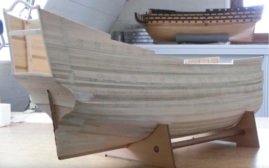
This is just beautiful, clean work, Mark. I love the careful spiling of your planking on the round-tuck stern. This is a very difficult thing to do seamlessly, and you nailed it. I am also interested in the middle strakes of your hull planking, just below the main deck level, which appear to have the chatoyant character of alternating grain. If this was selected deliberately, you chose well. It looks fantastic!
- Keith Black, Some Idea and druxey
-
 2
2
-
 1
1
-
-
-
I am in total agreement, David. If it feels too much like work, then you probably won’t get there.
- druxey, GrandpaPhil, Some Idea and 1 other
-
4
-
A number of you have reached out and said a lot of really complimentary things about the work on these railings, and the model in general. That is very meaningful to me, and I really appreciate it!
I do want to take a minute, though, and talk a little bit about process, as there may be people watching along through all of this and thinking “well, I could never do anything quite like THAT.”
My resounding reply to anyone who may be feeling that way is that you absolutely can achieve these things.
While it is true that I have developed fine motor skills over the course of my lifetime, and they are essential, I think what is often considered “talent” largely boils down to one’s powers of observation.
Here is what I mean. Whether it be 17th Century French warships, or 18th Century American longrifles, or Art Nouveau furniture - to name my three most passionate period interests - I think it is essential to constantly be on the search for previously unknown and increasingly better examples of these things, so that you can better appreciate what constitutes Good, Better and Best (Israel Sack’s guide to period furniture) examples of any given type. This is why I love scrolling through Pinterest so much. Every so often, the algorithm sends me a gift of something I had never seen before!
More than any other skill that I posses, I believe it is my ability to really home-in on, and scrutinize the details of a thing, that has enabled me to recreate them with reasonable verisimilitude to their times. I really pore over drawings and photographs for excessively long periods of time, and often revisit them until I understand the details well enough to actually draw them.
This has always been my litmus test; when I can finally clearly visualize something in my mind’s eye well enough to draw it in a clear and detailed way - then, I absolutely know that I can make that thing.
Perfection is never my goal. All aspects of this model, or anything I have made, are slightly irregular. What I am trying to achieve, though, is the uniform application of my powers of observation, in concert with my dexterities to the object in-hand. In other words: I am committed to maintaining a certain standard of execution. The more contemporary models you look at, the more you will come to realize that they all have in-common these slight irregularities of shape and proportion.
This is why the project has carried on for as long as it has. Soleil Royal is a magnificently complicated vessel, and I have endeavored to include as much of that detail as I reasonably can.
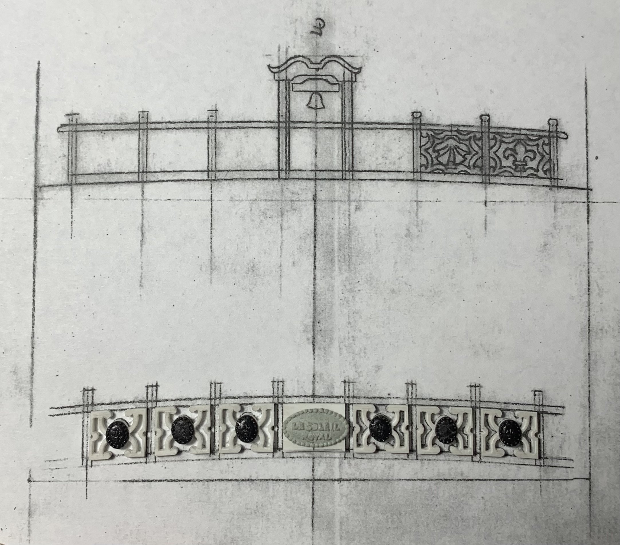
The QD breast rail is emblematic of this process. When you really study it, you can find all manner of a-symmetries:
However, as with painting, it is my habit to work an individual panel, for example; get it fretted pretty close to where I want it to end up; regularly flip the work from front to back to make sure I’m not cutting out of square; and, finally, to come back and re-work each panel so that they are as consistent as I can make them.
The secret to all of this is just time. I enjoy the process, so the enormous amounts of time I spend whittling away don’t really matter too much.
In closing, all of these things you see me doing were learned right here in the process of making THIS very model. My skills have improved tremendously over that span of time.
These things are achievable. You can do them too, and the process of learning to opens doors to what you are capable of within the hobby. You are suddenly no longer constrained by whatever kit manufacturers deem profitable enough for manufacture.
Thank you for indulging my reverie.
All the best,
Marc
- Archi, Pirate adam, GrandpaPhil and 14 others
-
17
-
Thank you, Gentlemen. I am continually amazed by what 3D printing now makes possible, however, I always like the slight irregularities of a handmade thing. For me, this is the fun part of the hobby; you start out with scraps of sheet plastic, and at the end of it you have a super-detailed breast rail.
- Siggi52, scrubbyj427, 72Nova and 3 others
-
6
-
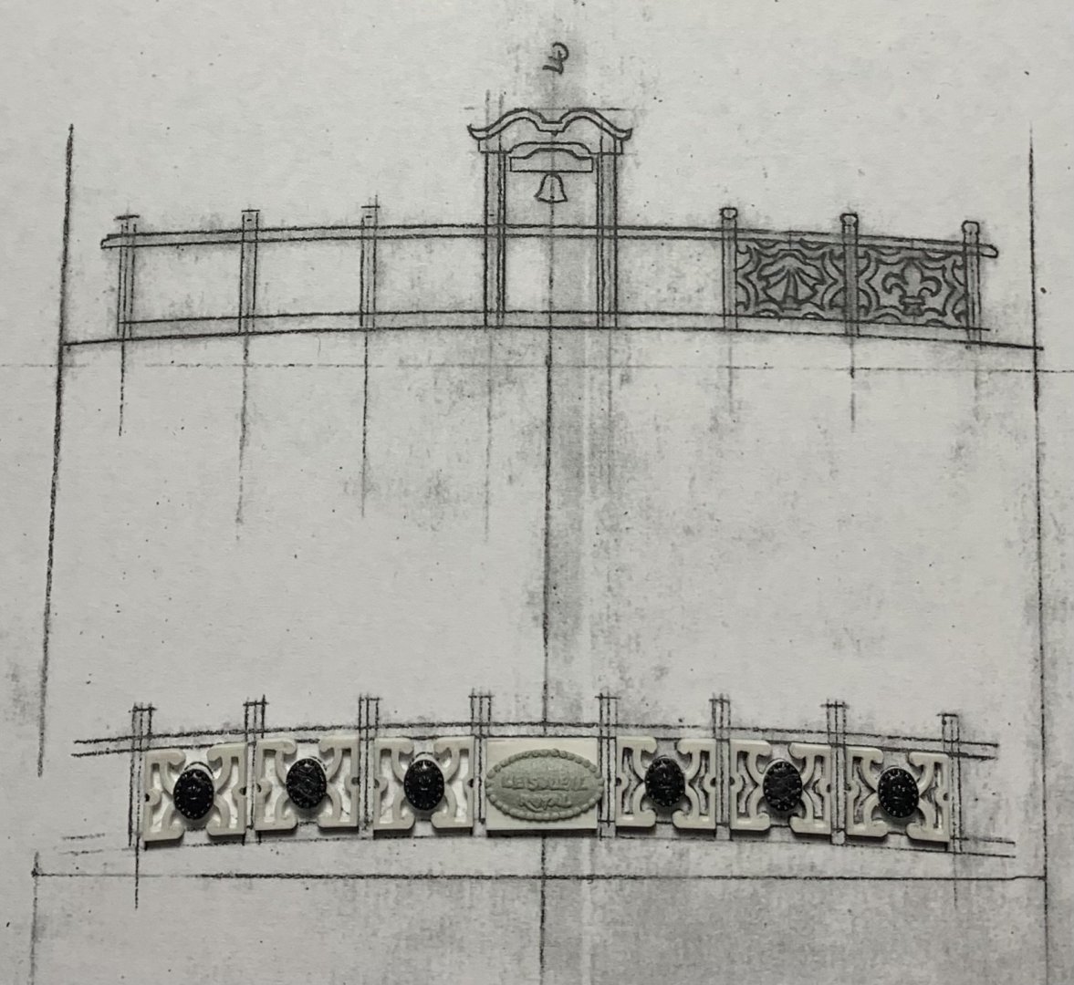
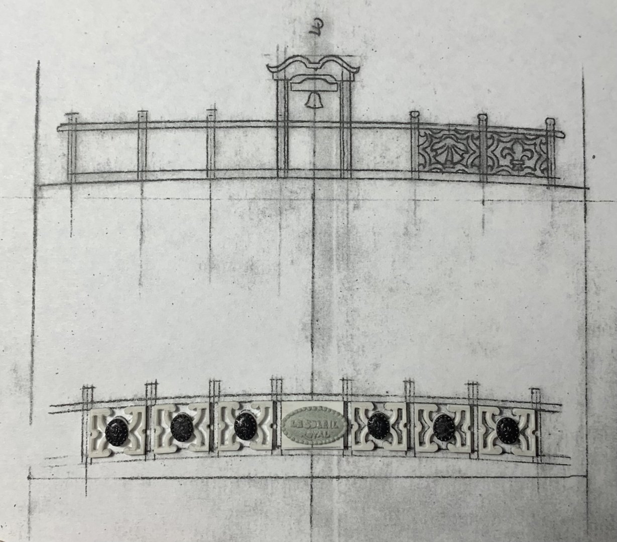
I have decided to keep my momentum going, and I am currently in the process of designing and making my QD breast rail.
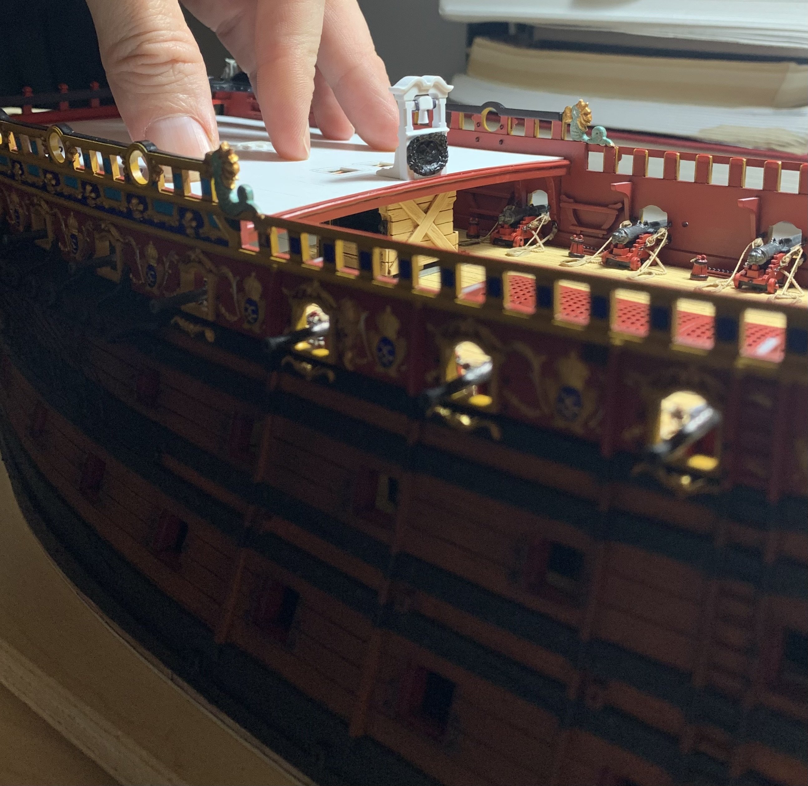
In a moment of pre-install vanity, here is the f’ocsle belfry placed:

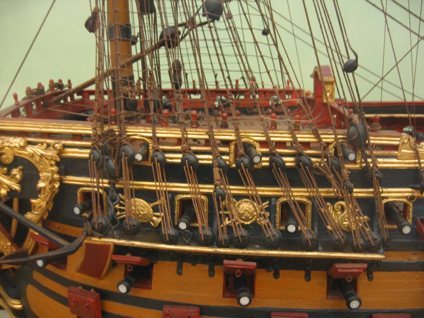
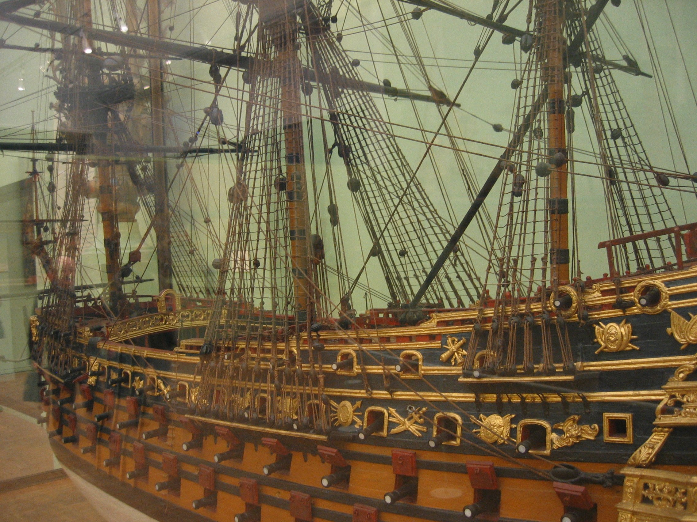
I wanted to be sure that the scale of the thing looked right, although I did mock-up the main stay during the design process and the top of the belfry is well below it. With the Louis Quinz model as my reference, I think it looks just about right:

photos courtesy of Marc Yeu
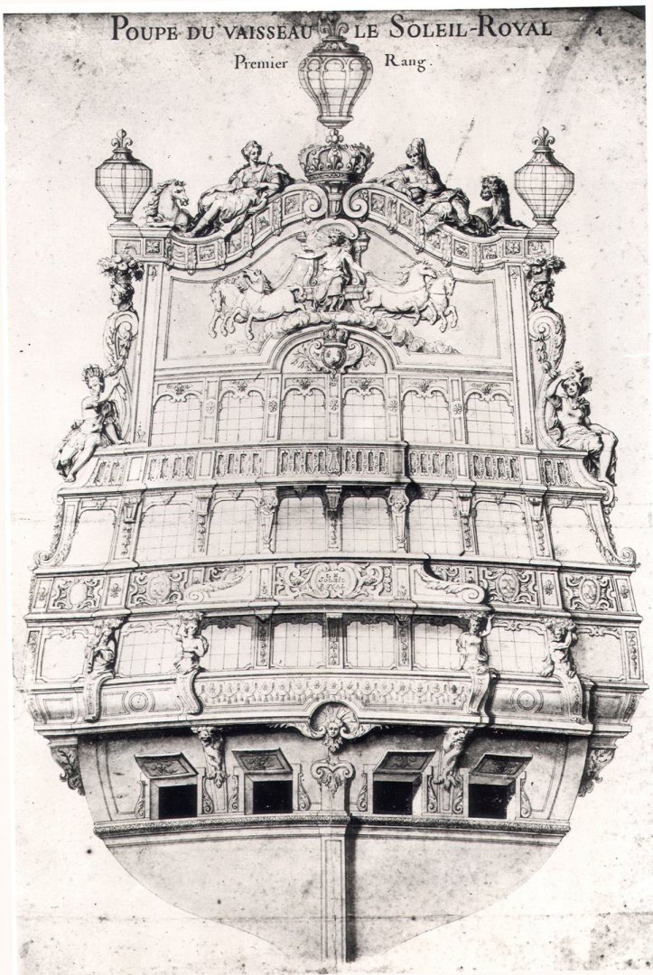
Continuing the theme of bringing the outboard details, inboard, I used the main deck level balcony rail as my design reference:
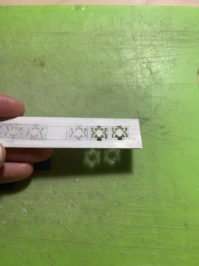
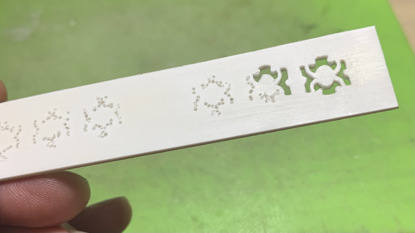
The wonderful part of this hobby is that you are constantly learning and refining technique:
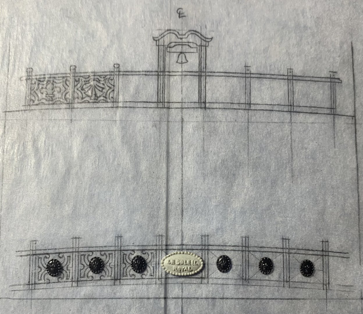
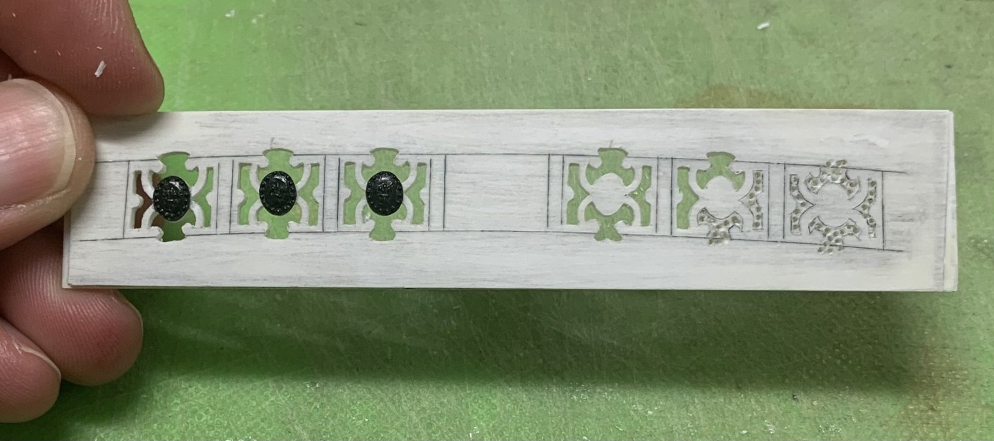
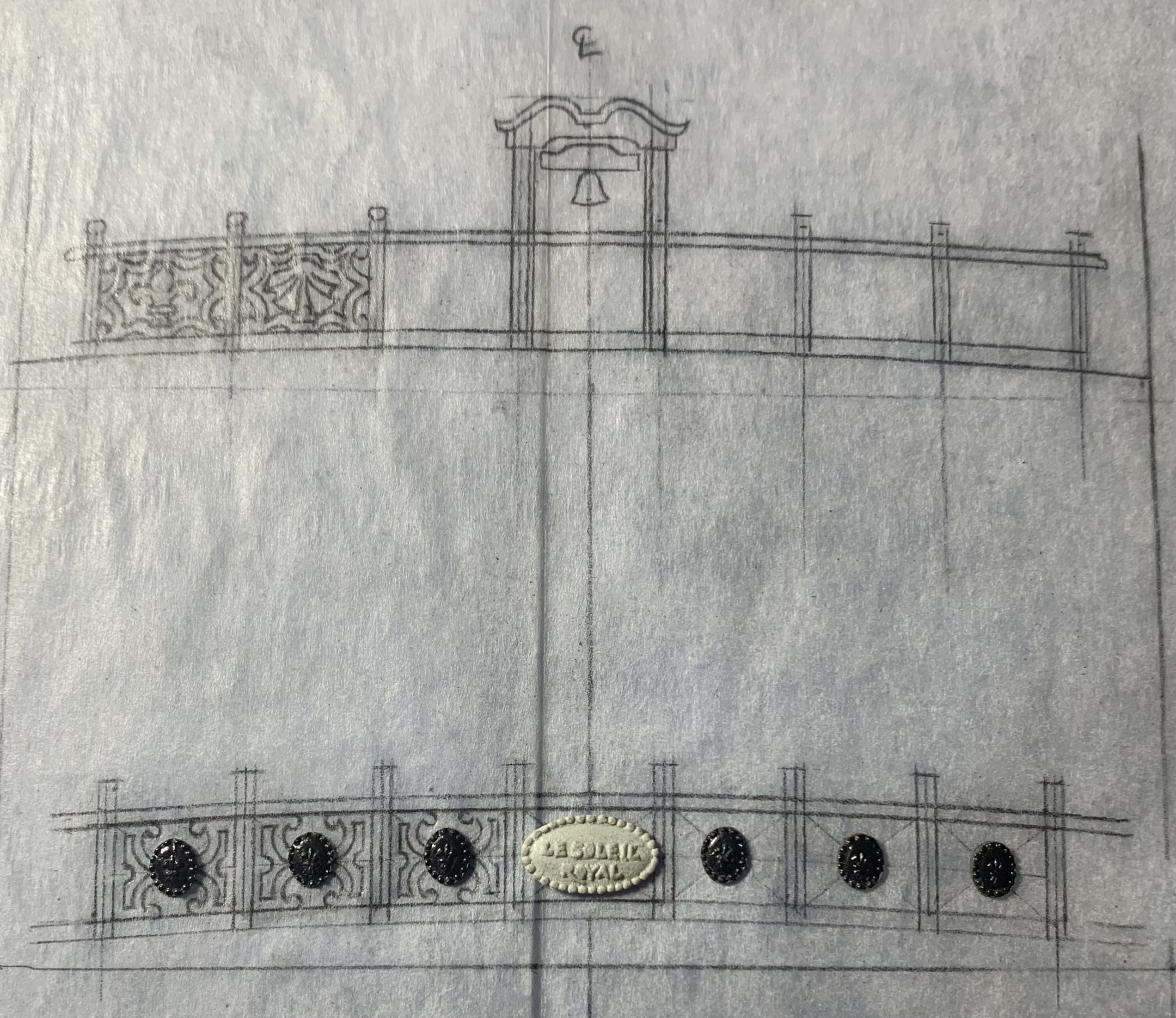
In order to more uniformly draw the three port side lattice frames, I realized I could create a series of reference lines (diagonals and a mid-line) that would help me to layout these shapes in a consistent way.
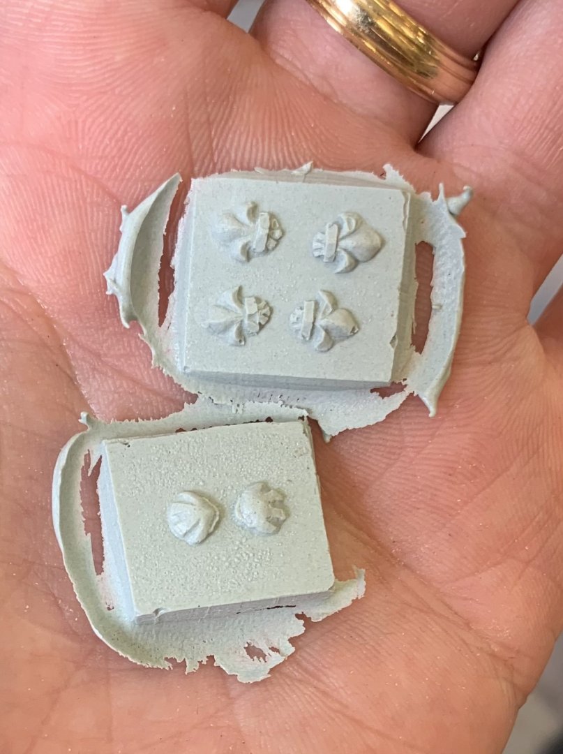
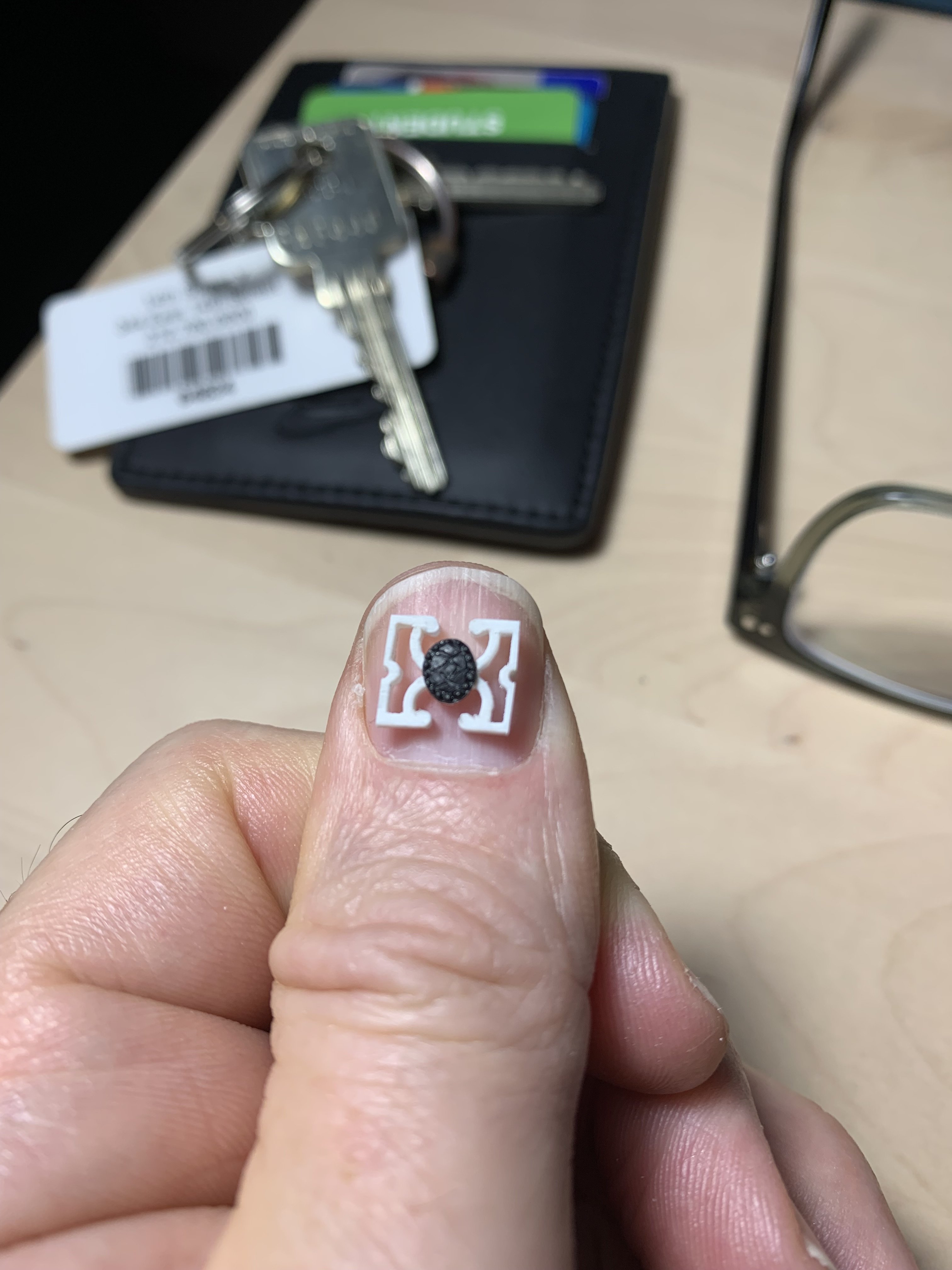
I was lucky that I still had six oval cartouches that I could extract from the kit QGs. It was necessary, though, for me to cast another name cartouche out of BONDO, which came out with perfect casted detail.
The oval cartouches are cast with tiny fleur-de-lis. On each side of the central panel, I will engrave the central ovals with the crossed-Ls monogram of Louis XIV, while the outer ovals will remain fleurs.
Little by little, we are getting there! Thank you for visiting the build!
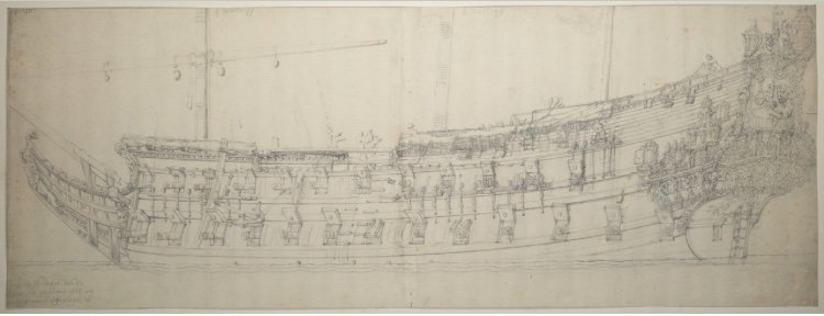
Bonus - I found this amazing VdV portrait of an unknown Dutch two-decker. I just love the beautiful silhouette these Dutch ships cut on the water:
-
Thank you, Dan! Although knees can be difficult to rehab, it is good that you are doing this sooner, rather than later. In fact, once you have fully rehabbed, you will probably wonder why you waited so long. To be free of that sort of pain is transformational!
- druxey and GrandpaPhil
-
2
-
Brilliant stuff, Matthias
- Keith Black and Canute
-
2
-
I’ve been plugging away on this f’ocsle breast rail and belfry, here and there, when I can.
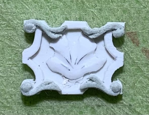
I made enough BONDO scroll ornaments so that I didn’t have any difficulty selecting for the best and most consistent examples:

I coat them with a little thin CA, once they’re in place, just as a precaution - in case there were any micro fissures or fractures.
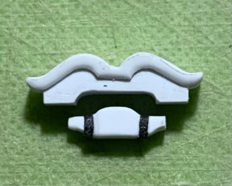
The belfry came together sequentially.

Turning the bell took a few attempts. I overheated the plastic, on the first try, and the bell winged-out on me.
I made the cap rail from a couple of layers to give me a thickness of 3/64ths.


It was necessary to fit a center section of caprail to the belfry assembly. The side sections will be mortised for the timberheads, and joined to the center section later.
All-in-all, I’m really pleased with how it’s coming along:


As always, thank you for taking time out to look-in at this build.
More to come…
-
Magnifique! Tres Belle!
-
You have really made a lot of progress, here, Mark. Just beautiful work all around!
- AJohnson, Keith Black and Some Idea
-
2
-
1
-
Nicely faired hull, Bill!
-
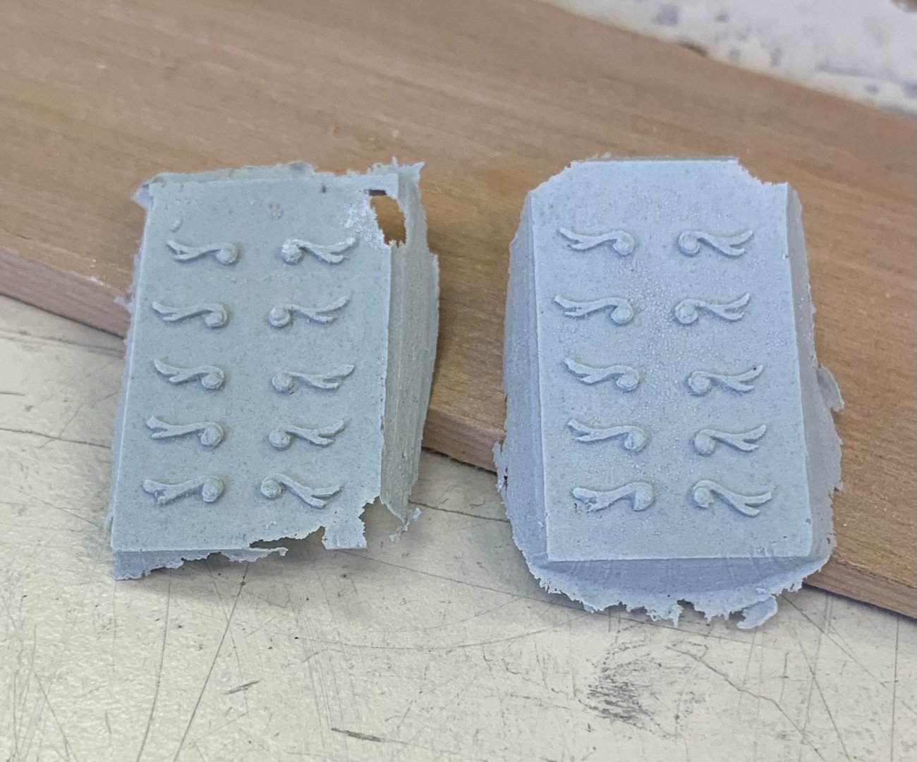
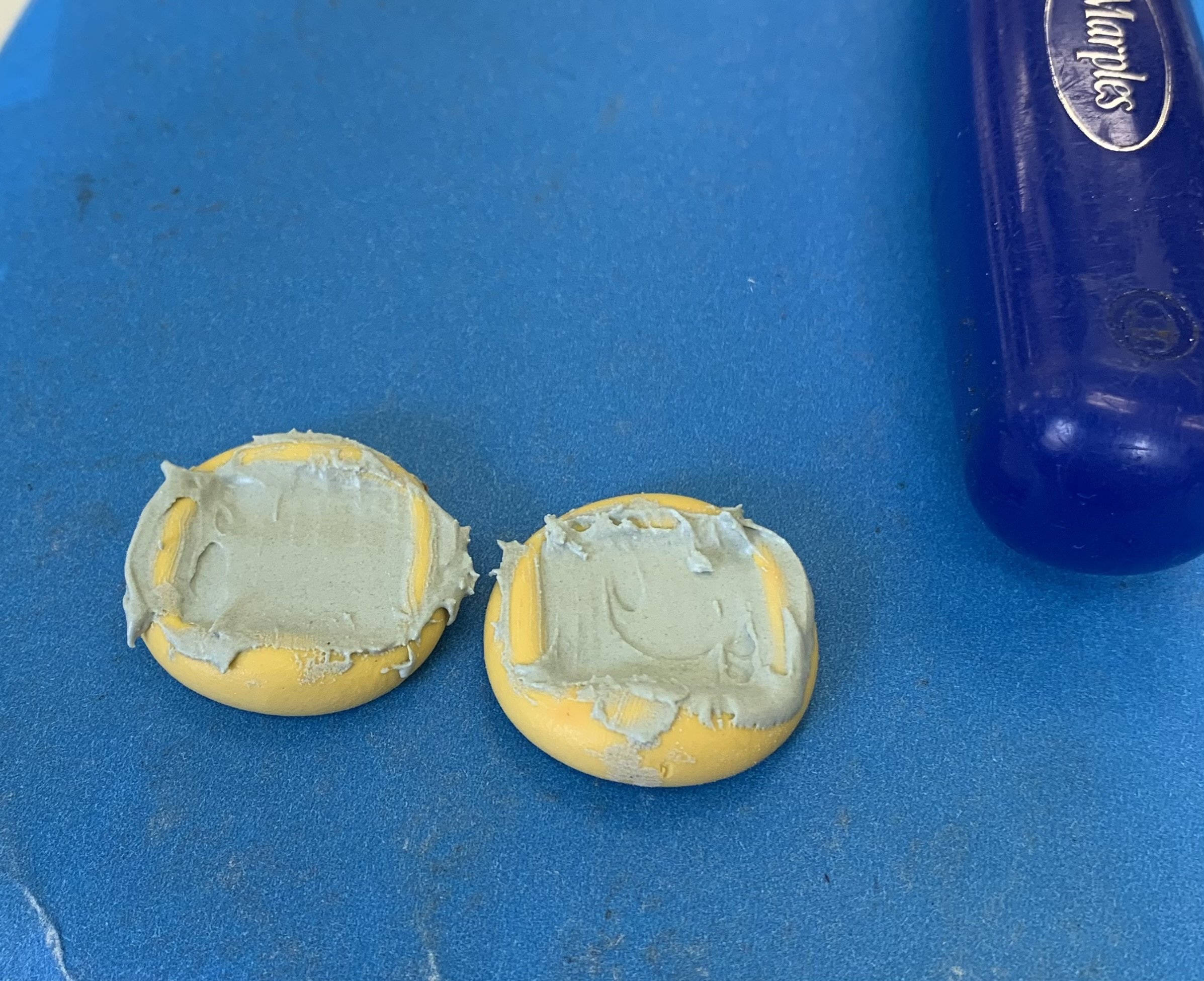
Well, I’m happy to report that the BONDO experiment was a success! I made a few fleur and shell casts to see how the material might release from the moulds.

They released with even less effort than the Allumalite resin castings. As with the resin, small air pockets were an issue, but the crispness of detail was very satisfying, overall.
For the squiggly scrolls, I decided to press a small amount of BONDO into the moulds with the pad of my finger, hoping to press out any air pockets. I then applied a thin backing layer so that I’d have something to hold onto, as I wasted away the ground. This time, perfect castings:
Wasting was easy with the Dremel drum sanding attachment, followed by lap sanding across a sanding stick with finger pressure. Checking against a back-light, you can see where the ground is thicker or thinner, and you can adjust your finger pressure accordingly. You sand until you can just begin to see the castings releasing from the ground.
I cleaned up a set to see what they looked like on a panel. I’m on the fence about this, at the moment:
I also took some time to trim the panels so that they fit precisely within the parameters of the drawing. Because all 6 panels are produced from only two master drawings, they don’t all perfectly mirror to the other side of the drawing. A little fine-tuning was necessary:
I made the yoke for the bell. The iron bands are simply black construction paper:
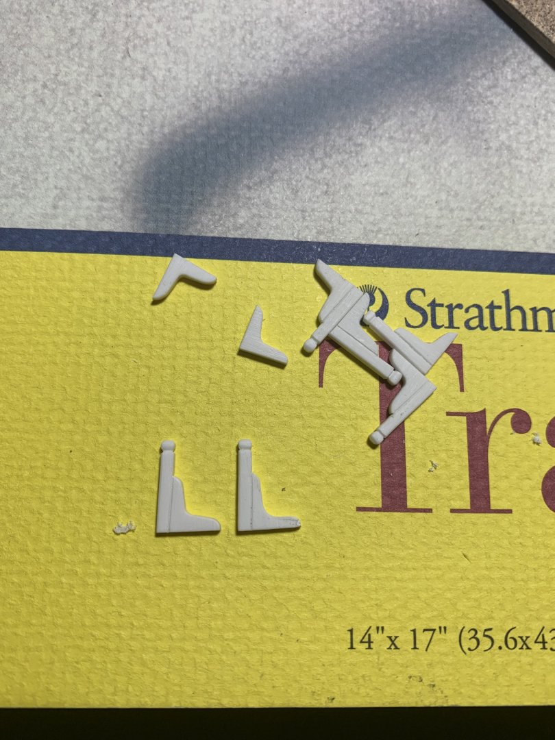
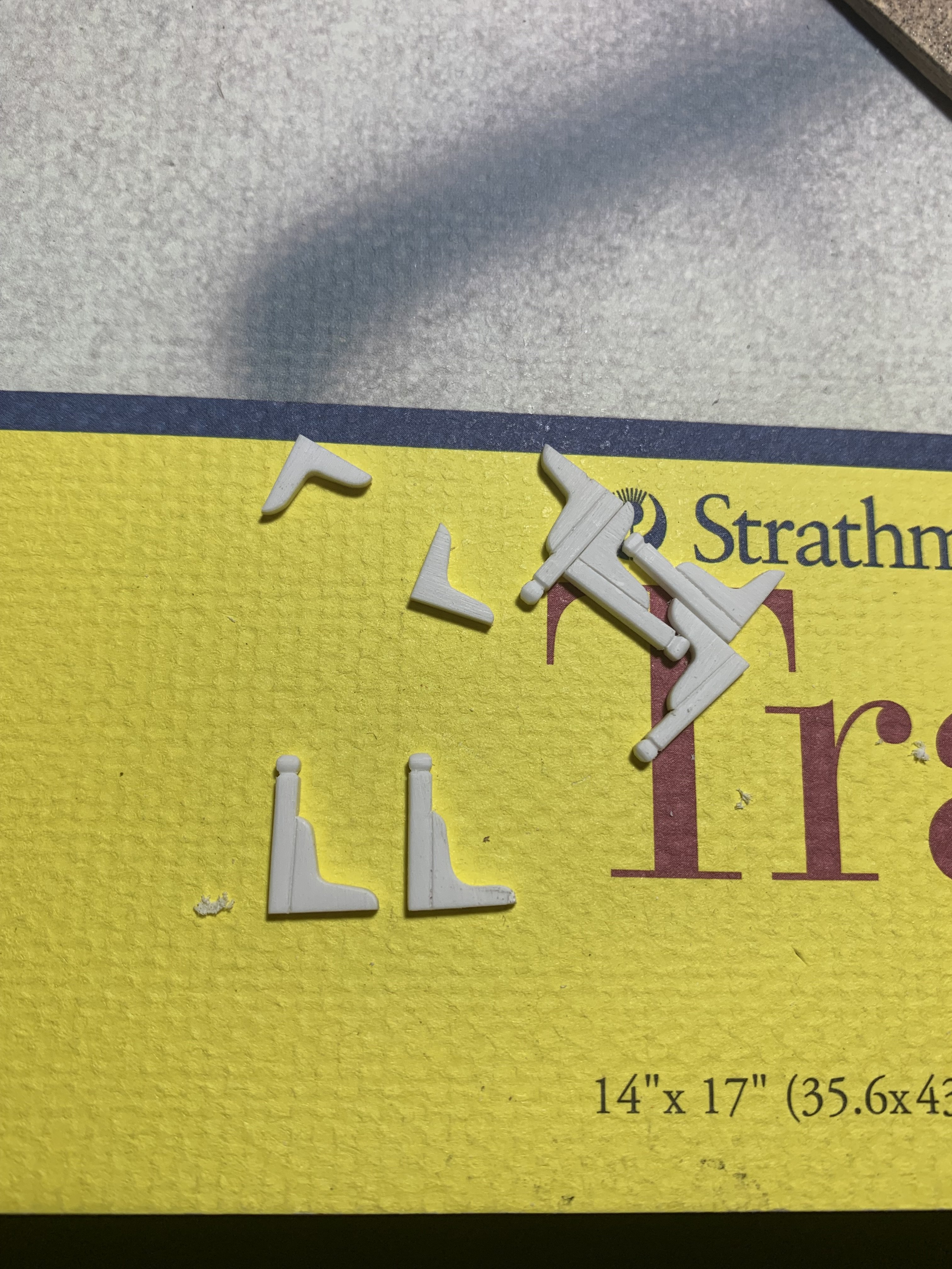
I’ve also made the six breast-rail stanchions. I realized that the knees I patterned (left stanchion) were a little too heavy and out of scale, so I trimmed them back a bit (right):
I guess I didn’t save the bell (90’s reference), so I’ll have to turn one from Screetch!
RIP, Dustin Diamond
-
Brows on the two dolphins above the penny look just right to my eye.
-
-
Nicely done drawings, EJ. Now, though, I’m going to be a genuine PITA, once again. Why no deck camber?
In smaller scales, this omission is less noticeable, but your model will be quite large and this will jump out at the viewer because - apart from the practical purpose of watershed, all elements of the ‘tween decks bulkheads will read very flat. These early 17th C. ships are all about the curves.
For the sake of no-one will ever see it, I can see not worrying about the lower decks, but the visible decks are a different level of consideration, IMO.
I mention these things because you are early in the build, and have time to consider them. It’s a big project, and I don’t mean to be annoying, but I want you to be happy with the results of your labor.
- Ian_Grant, Paul Le Wol and CDR_Ret
-
3
-


HMS Montague 1779 by garyshipwright - 74-gun Alfred-class
in - Build logs for subjects built 1751 - 1800
Posted
Gary, this all just looks incredible. Really nice progress, and great to see you active again!
Best,
Marc