MORE HANDBOOKS ARE ON THEIR WAY! We will let you know when they get here.
×

Mike_In_RI
-
Posts
276 -
Joined
-
Last visited
Content Type
Profiles
Forums
Gallery
Events
Everything posted by Mike_In_RI
-
 Ken, I really like the way you modeled the sail. It looks great. It's now on my list of potential ideas to plagiarize emulate. Well done. Mike
- 238 replies
-
- 2
-

-
- sloop
- providence
- (and 1 more)
-
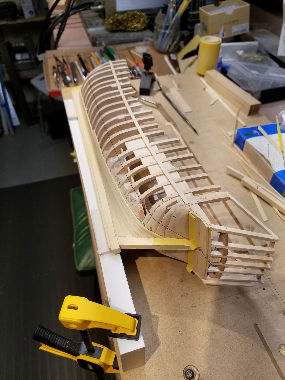
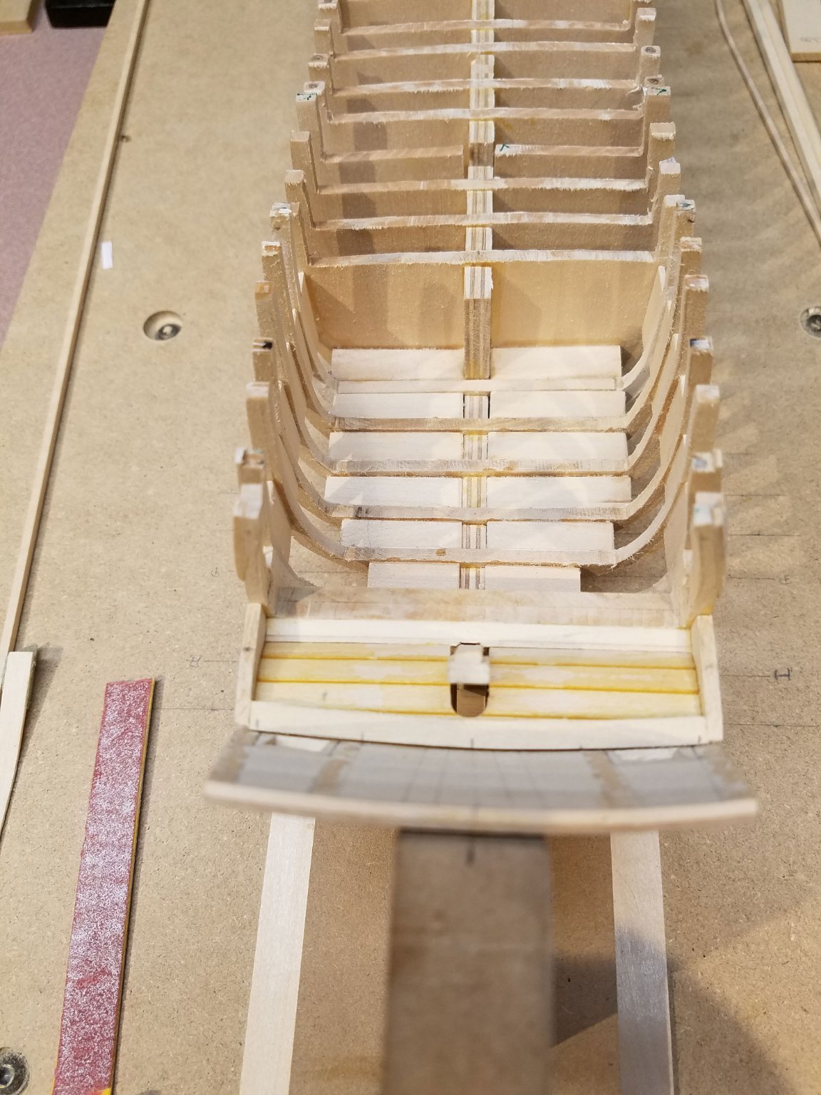
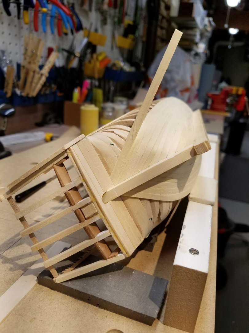
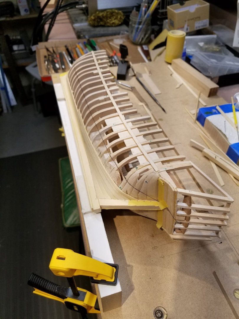
Thank you again for the likes. Just a quick update. Thinking it might be more risky to leave the (1/8" x 1/8") frames exposed for too long, I began planking the hull. The AYC planks were originally ripped to 3/64" however I have thinned them down a bit for easier bending around the tighter curves toward the stern. The 1/32" batten at the shear is temporarily placed in the position of the lower edge of the wales. A small milestone here... just today making it to the turn of the counter. Only six more planks needed to get to the bottom of the wales. At this scale, hindsight says a more narrow plank would have been easier to contour to the curves. Given that the hull will be painted, I have not simulated any caulking. However, I have lightly "broken" the edges of the planks hoping for the edges to show through the paint just a bit. ... back to planking. 😊 Mike
-
Nice use of the black on natural colors for the mast. I like that look. Your son will be proud of that stove for a long time. Well done. Mike
- 238 replies
-
- 3
-
-
- sloop
- providence
- (and 1 more)
-
Great Jean-Paul. Everything is coming together nicely... planking.. fashion piece... transom... well done. Mike
-
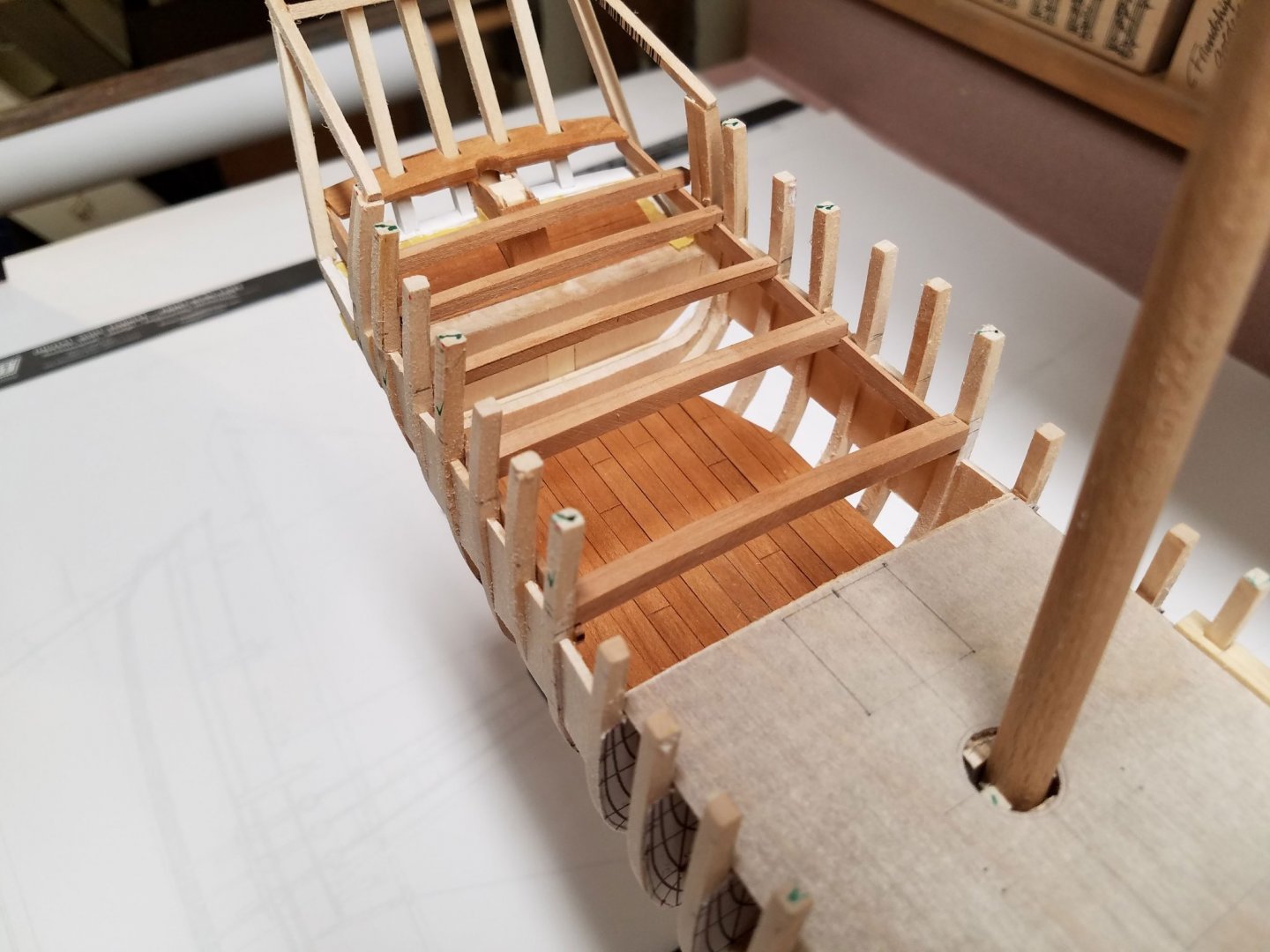
Thank you again for the likes. 'Well appreciated. Most of the additions shown here since the last update are dry-fit. The fairing in the cabin is done. The floor boards in the cabin are made from individual cherry planks glued to a 1/64" plywood backing and is removable in one one piece at the moment. There is one thin layer of shellac on the planks to bring out the tone but it actually looks a little too new. I may dull that down a little somehow. The quarterdeck clamps are in place and the beams are dry-fit so I can still do some carpentry in the cabin. Save for a little more shaping work at the bow, the hull is fair. The deck beams are faired and a false deck of 1/64" piece of plywood is marked out and dry-fit in place. 3/64" boxwood for the deck planking from thewoodmansshed along with other sizes for the great cabin are on order. I put a little time into a practice section of covering board (port side). It went fairly well but I expect it will be a lot more challenging with the stem curvature. Comments, tips & corrections are always welcome. Mike

-
The furled sail looks great Ken. Nicely offset against the black. Mike
- 238 replies
-
- 1
-
-
- sloop
- providence
- (and 1 more)
-
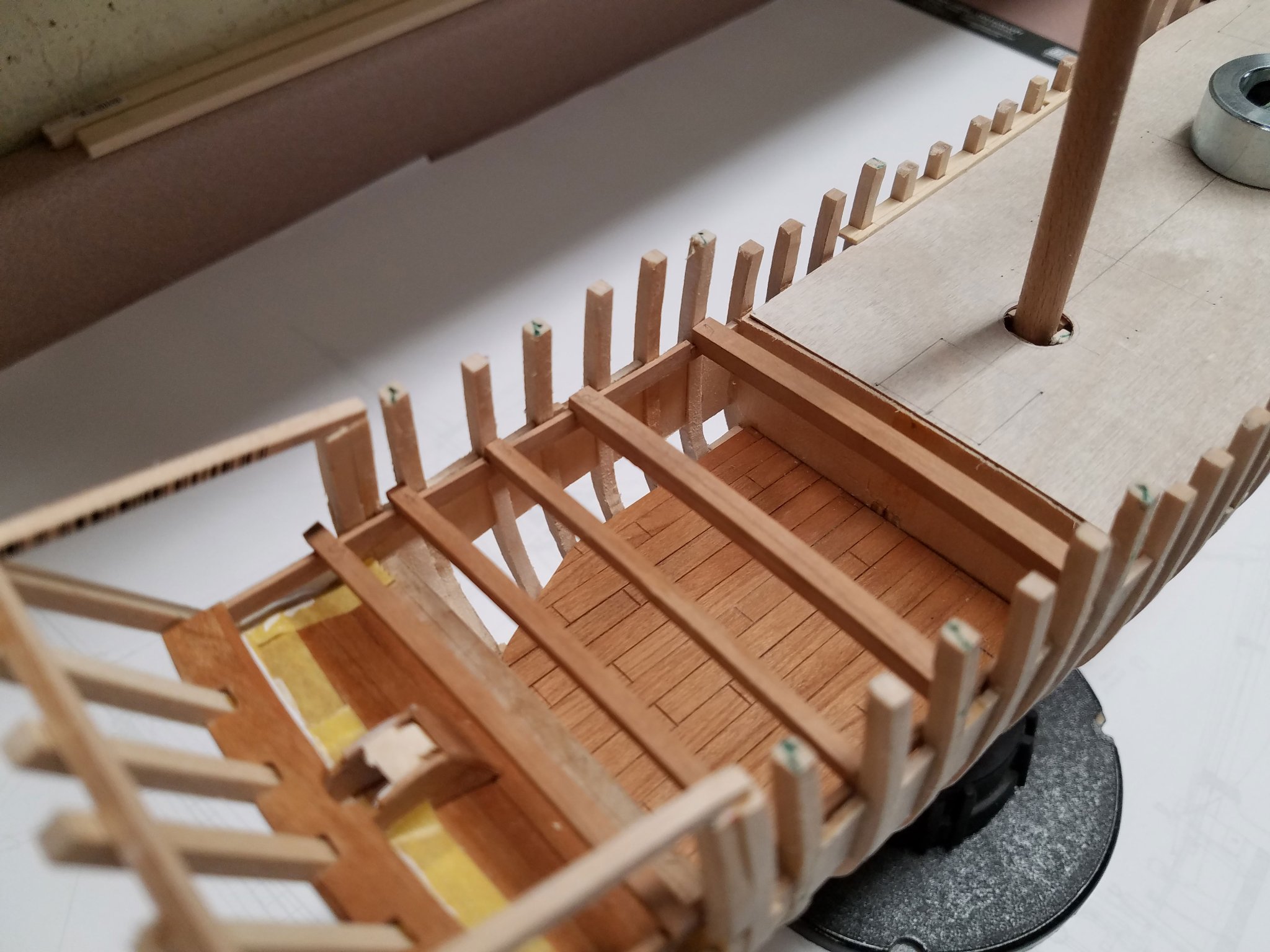
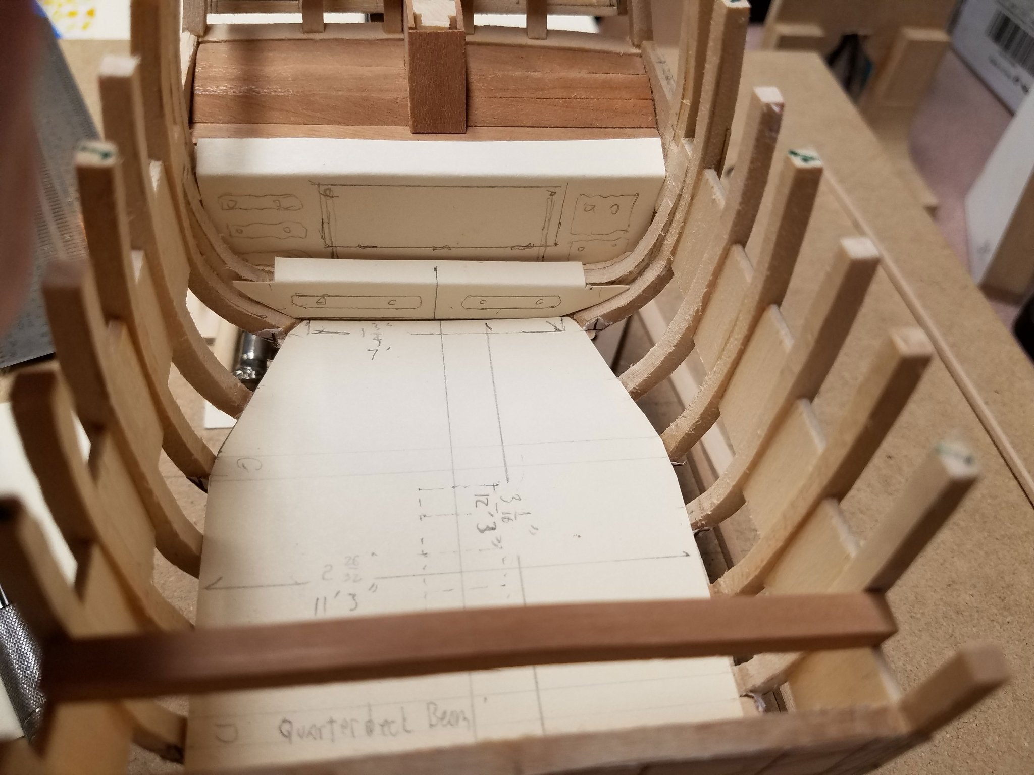
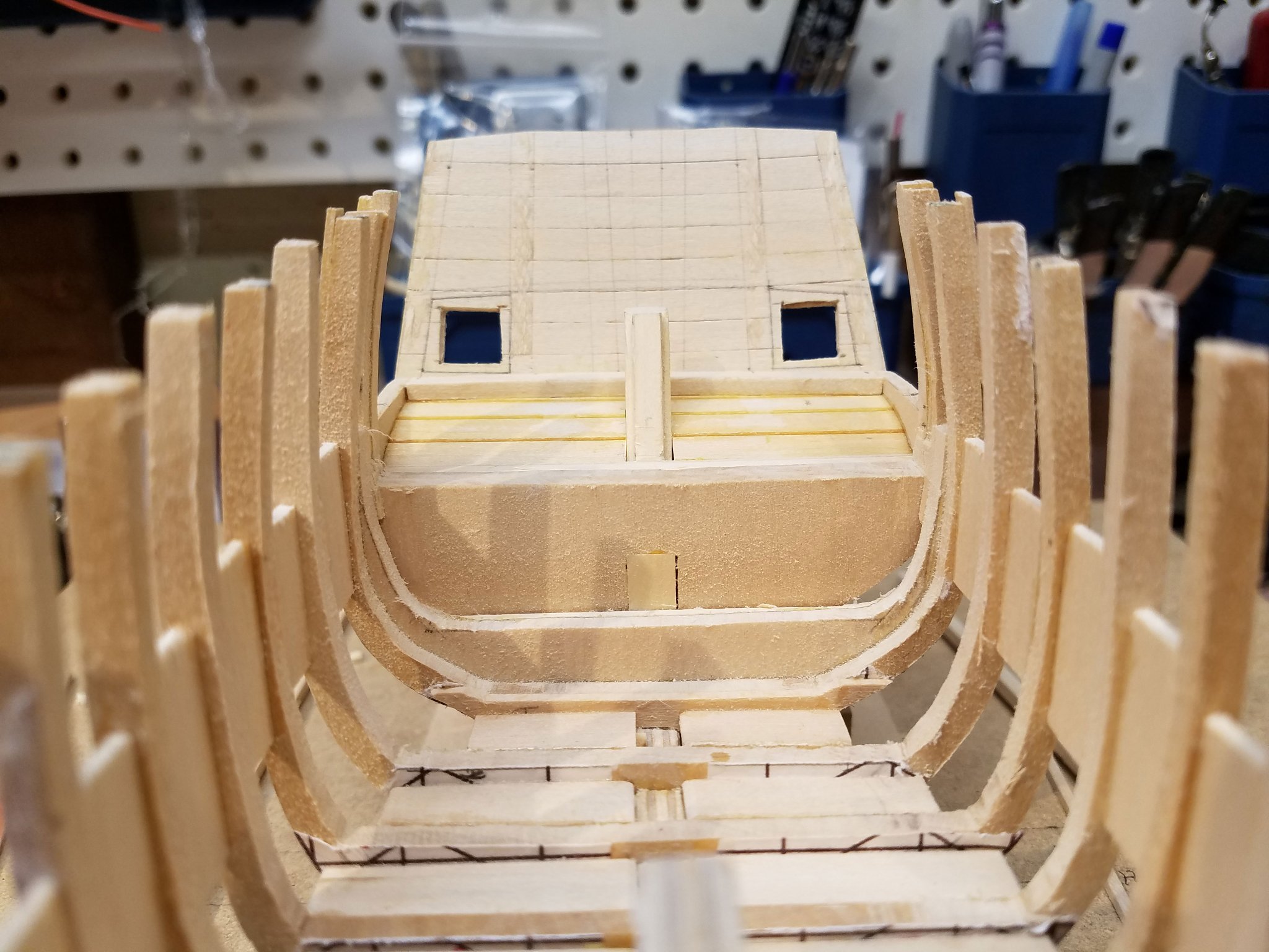
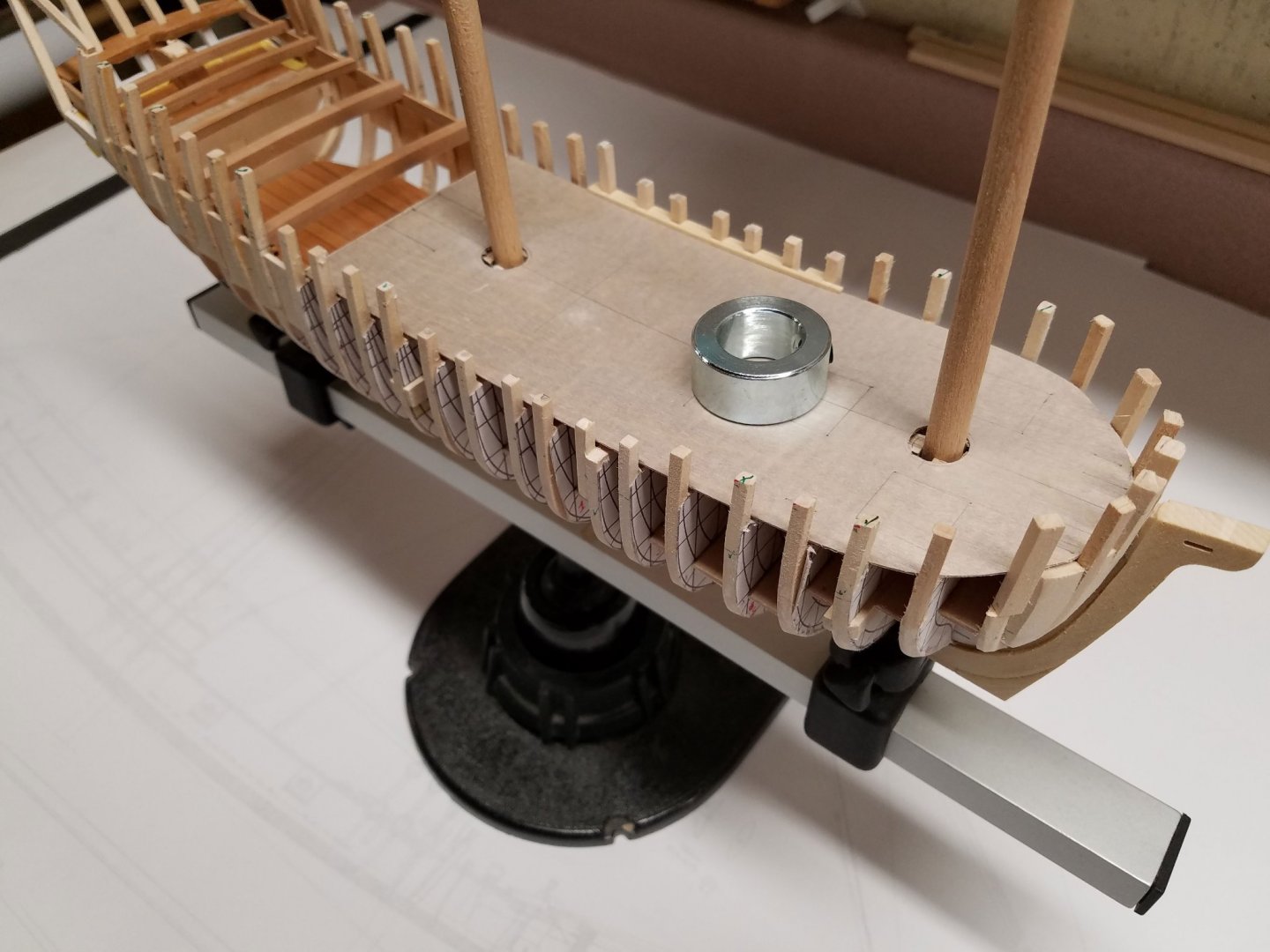
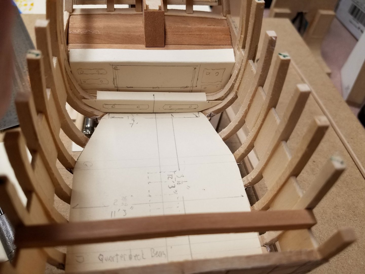
Time for an update. Thanks again guys for the input and comments. I must mention Randy's special behind the scenes incite in that this is my first scratch build and he has been a great help. Much of the work since the last update has been put toward removing wood rather than adding it. The forward bulkhead stanchions are just about to final size but still a little high until the cap rails go in. The forward deck is is about ready for the 1/32" false deck pending trimming in the bow stanchion curvature. Also, the open areas between the frames under the great cabin are now filled in with balsa. The trickiest part yet has been the stern deck beam. It's bowed up for the deck and back for the stern boards. It's also slanted back and in for the transom timbers and shaped underneath to allow for the port lights. The transom timbers are left long and temporarily braced. The sternboard is still a moveable template and the framing areas are left as open as possible while there is woodworking and painting to be done in the cabin areas. 'Sorry for the tilt in this photo.... a large wave no doubt. This shot shows the scale size of the raw cabin area. It's about 12' 3" long and 11' 3" wide narrowing back to 7' aft. The ladder leads forward in a decent. Once the tough-to-get-at work is done in the cabin area, the current plan is to fit he deck clamps and the final pair of futtock-ish frames just forward of the transom timbers. Mike


-
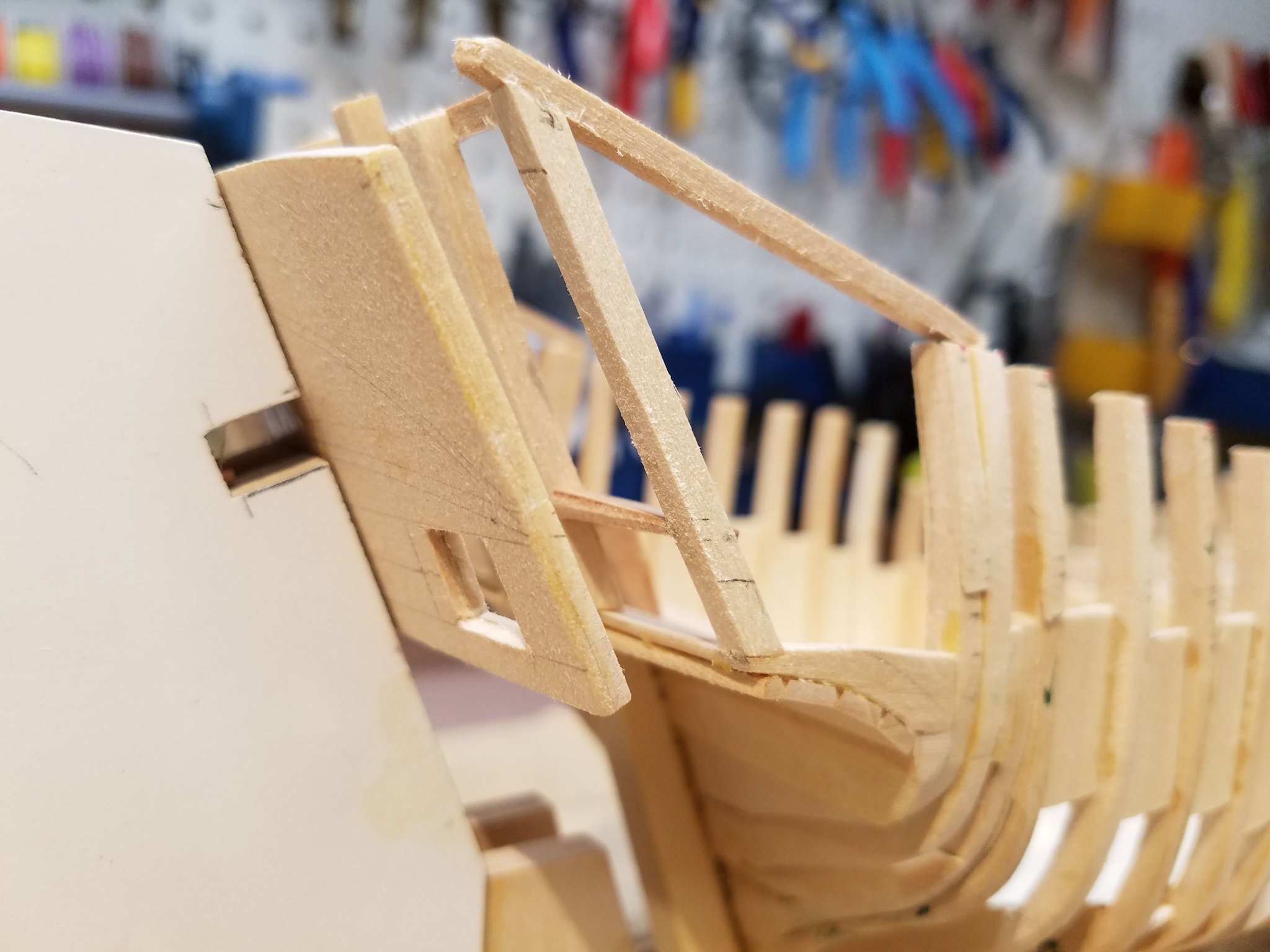
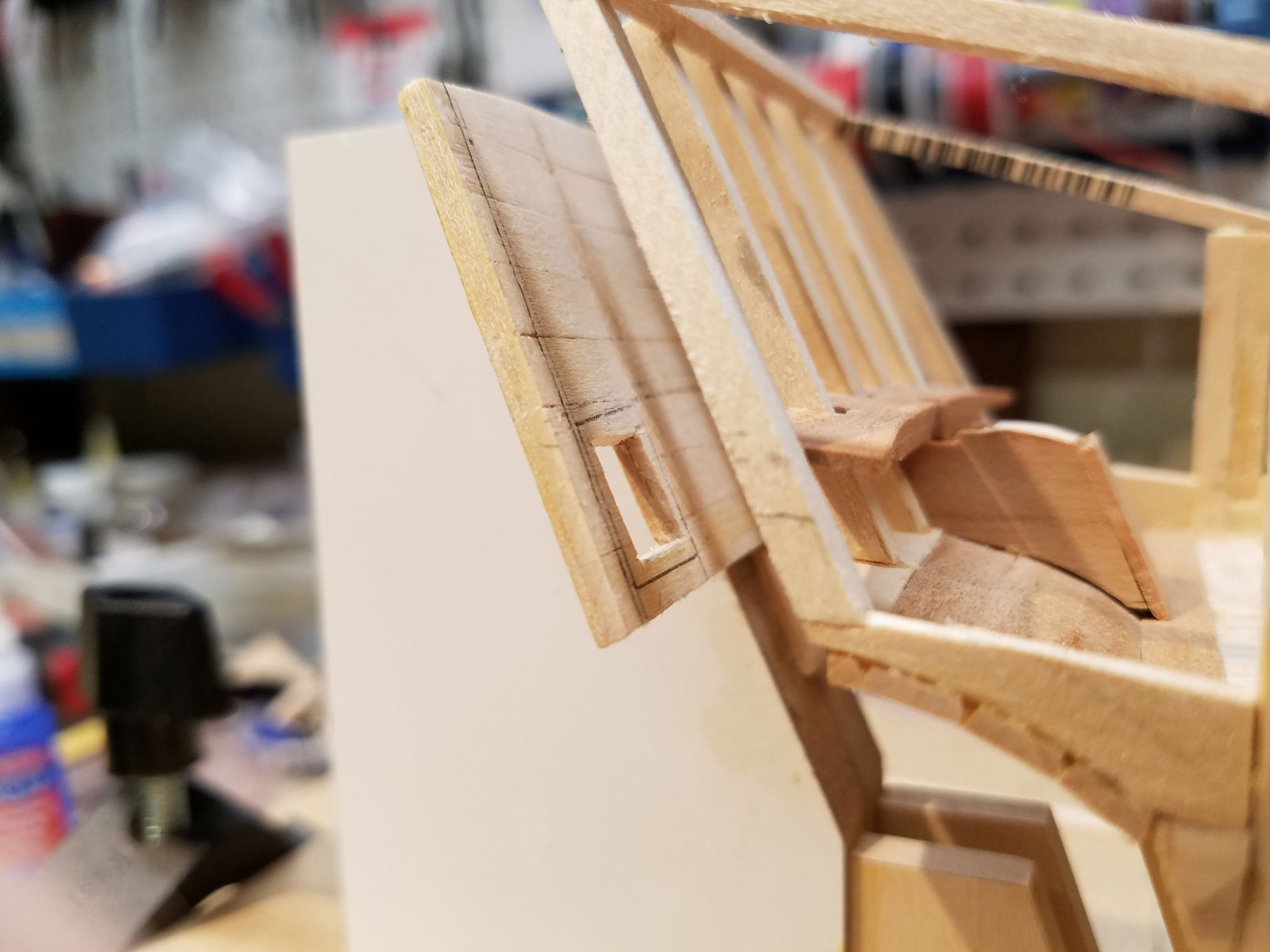
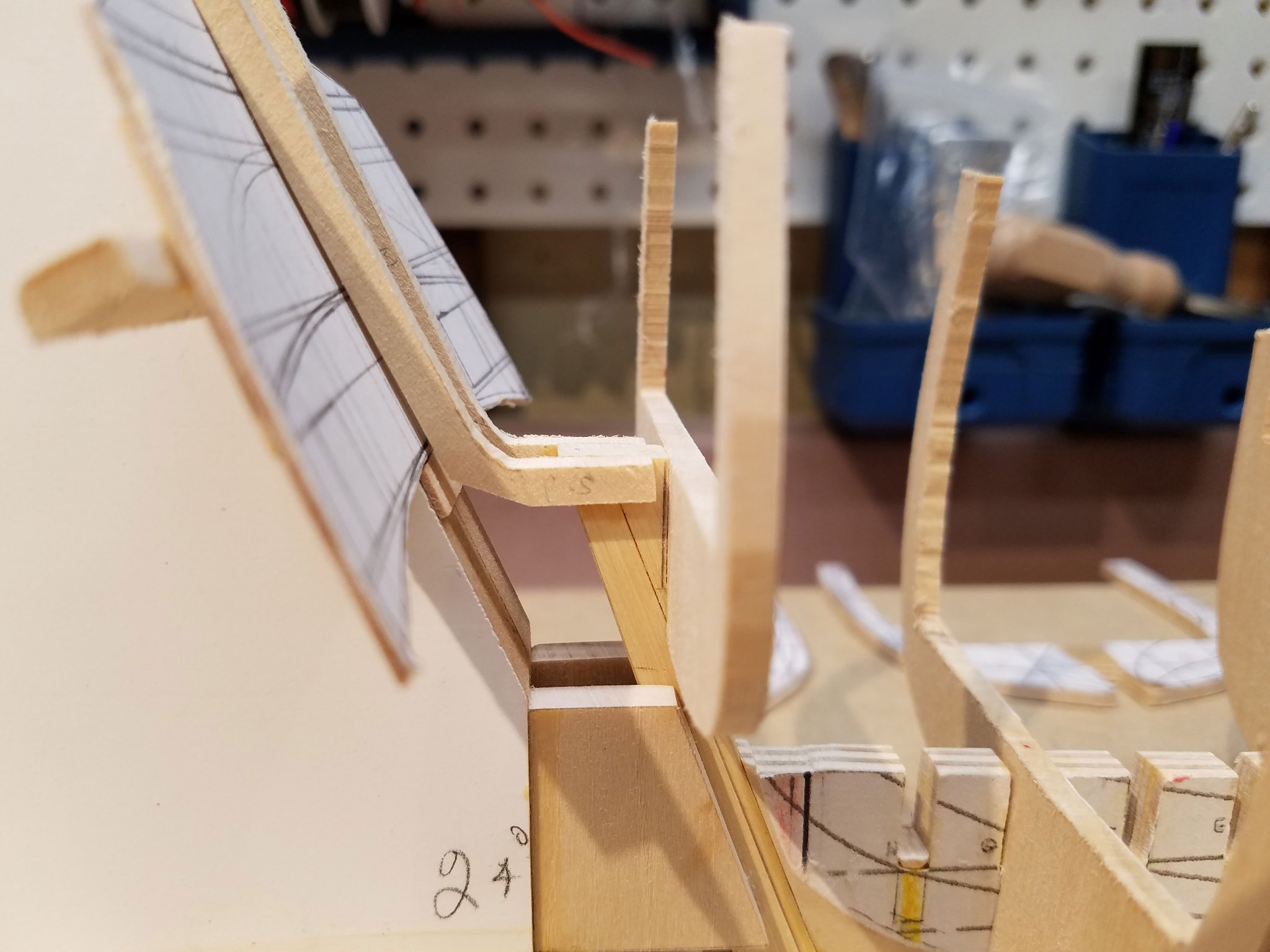
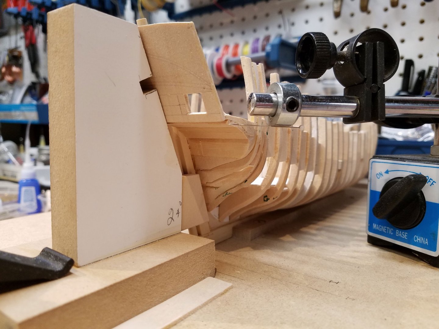
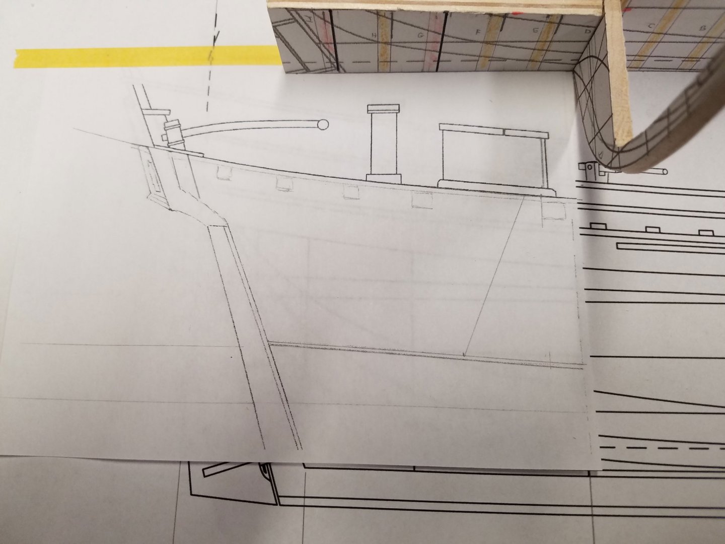
Thanks Lou ... "lined up" ... you hit the nail on the head. This scale, which I love to work at, made it difficult to use the more traditional method of fashioning six transom frames by hand and have all the angled surfaces line up. So I'm reversing the method and installing the counter first. I repurposed a dial indicator to help with this issue as well as marking out of the frames. You can see on the (dummy) stern board a curved outline just above the stern light. Per the plans, the curve should be coincidental with the quarterdeck planking and follows along the sheer which makes the height of the counter a key reference. So, the counter too high or too low either subtracts space from the cabin/sternboard or raises the quarterdeck. The counter is sturdy now and with no stern board in the way, I can reach into the cabin area more easily. Greg, thank you for that. I had been thinking about putting the wale in early to firm up the hull. You may have just saved me a lot of time! This being my first scratch build, forward planning is my shortest short-coming. Re:Rigging... thanks again for the heads up. I have the the Hahn Hannah plans and see your point about the rigging. In this case I'm comparing it to some shots of William F. Wiseman's Hannah that I recently took at the Mystic Research & Collections building and see a difference. That being said, my current strong point regarding rigging is that I know how to make rope.🤔 In that this model will (I hope) feature the great cabin and have a partially open quarterdeck, I expect to have minimal rigging or maybe have the stubbed mast look... or... so I'm not sure yet. Thanks again for the help and the likes. Comments are always welcome. Mike
-
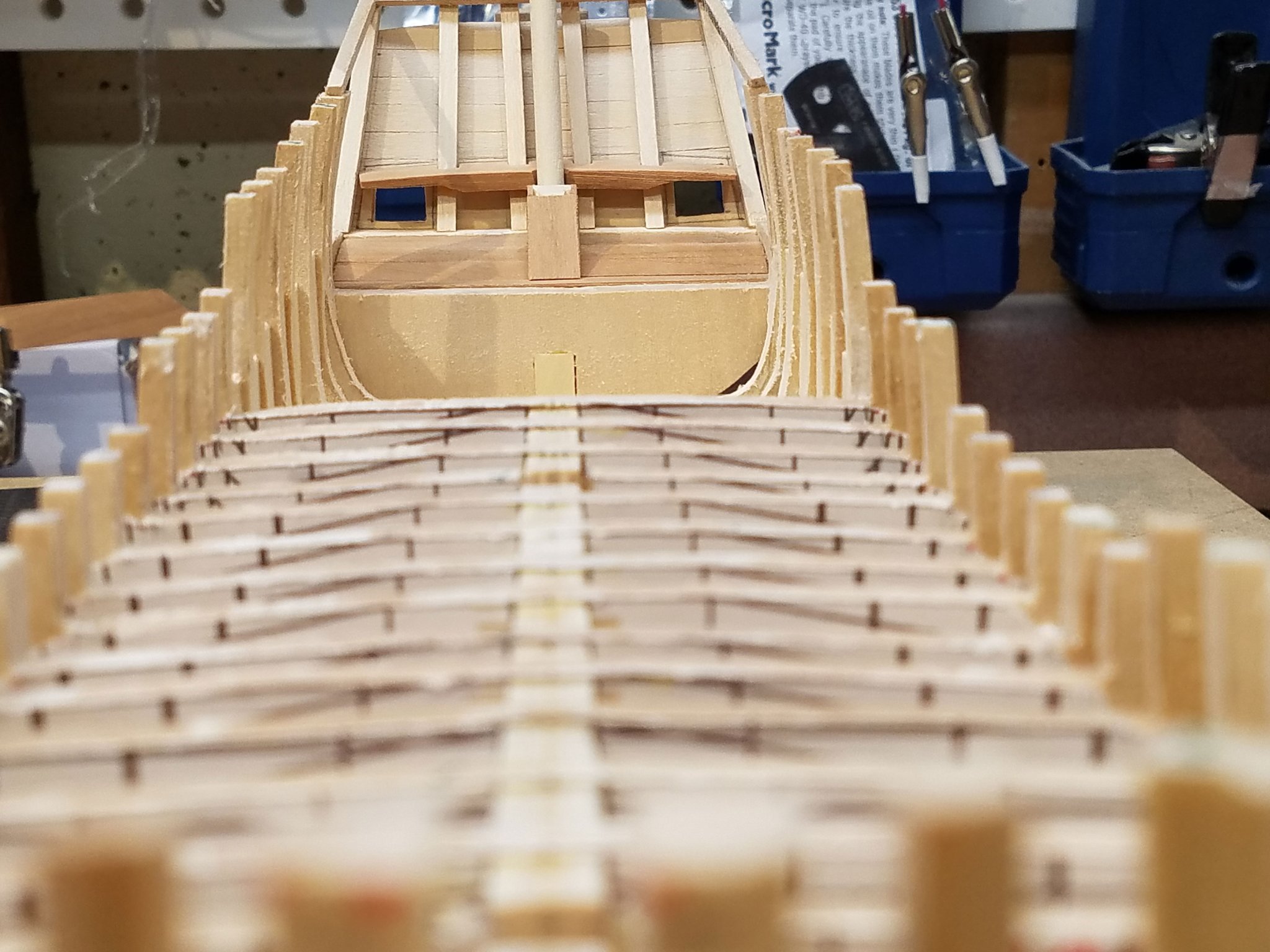
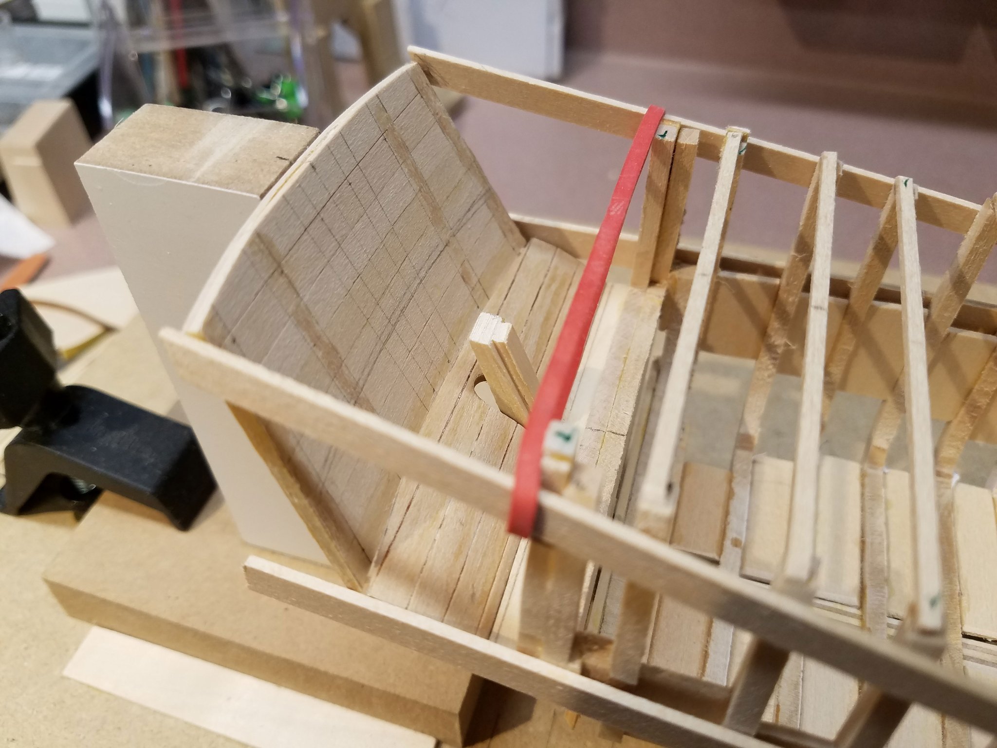
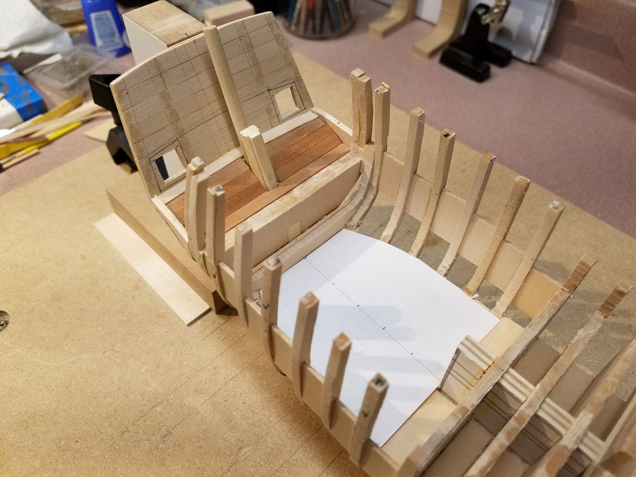
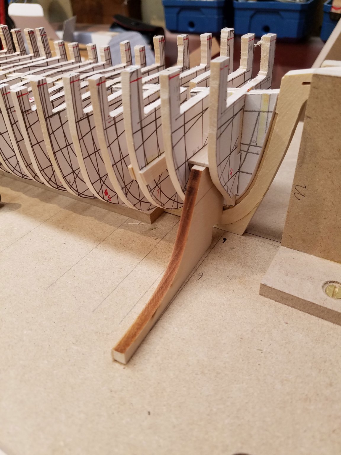
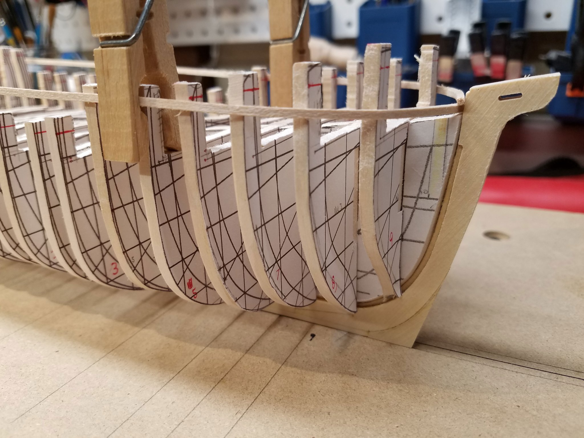
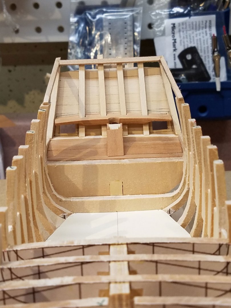
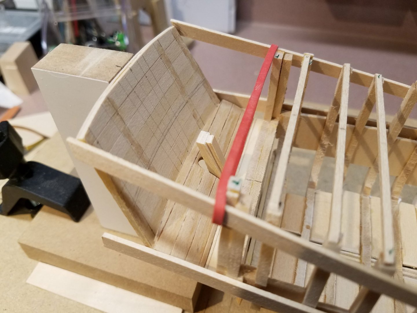
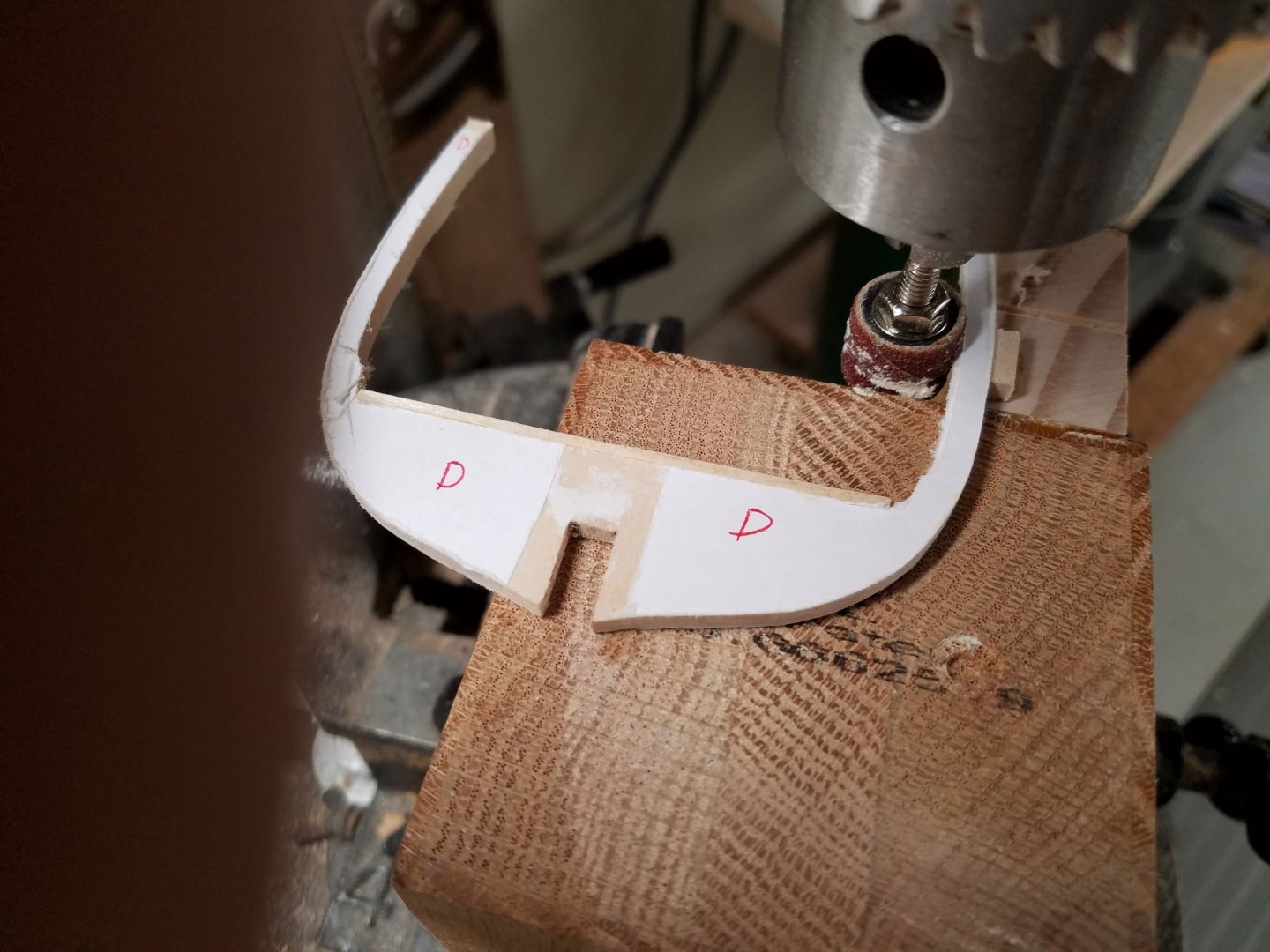
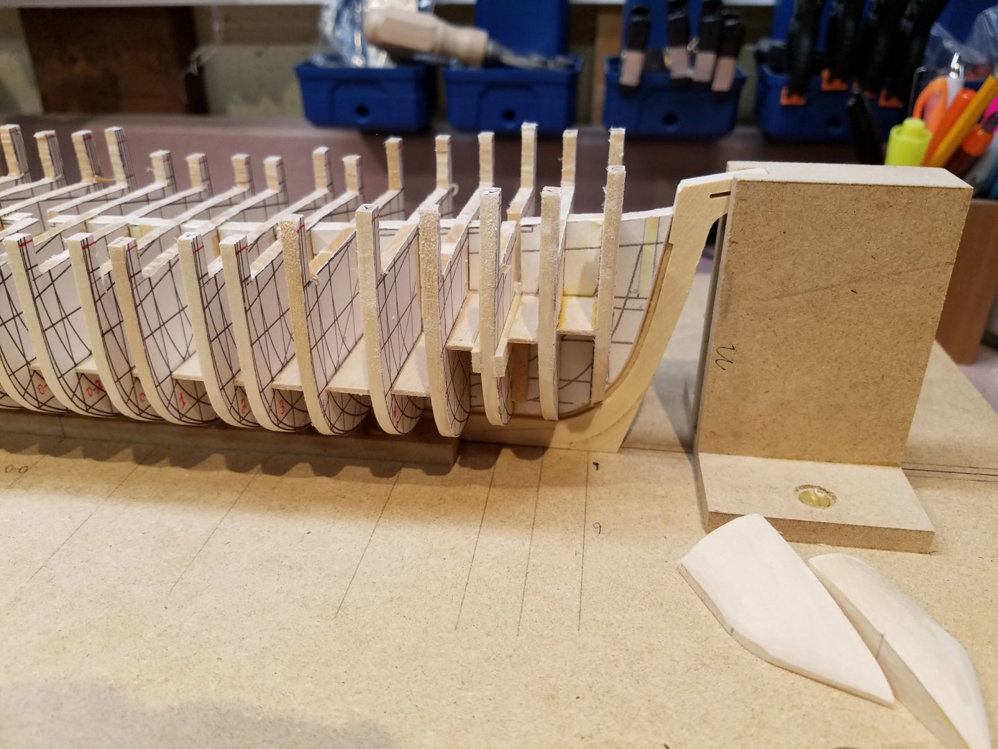
Since the last update, all the cabin frames are now in place. At this smaller scale (1:48) they are only 1/8" x 1/8" and fairly fragile so multiple spacers have been added between all the frames. Also, this shot shows temporary bracing across the top of the frames to keep them from changing shape. The wedge shaped piece attached to the stern post will accept the lower hull planking as it rises to the counter. It may seem a bit backwards, but the counter was fashioned and installed next to establish the height of the lower edge of the stern board. Once the counter is installed, the dummy sternboard can be temporarily placed which allows fairing of the quarterdeck frames. For now, the stern board will not be permanently installed in order to allow more room to work inside the great cabin which will be viewable through a partially open quarterdeck. The counter is made up of two layers of planking. The outer layer is bass wood and will be painted. The inner layer is cherry. My current thinking is to use a combination of natural wood and white paint in the cabin area. The exterior fairing is about 75% complete. Currently, I'm thinning the frames from the inside of the cabin back to 1/8". With POB construction, there isn't much more room to be gained without weakening the walls. Time to give some thought to the cabin floor layout. Any comments or suggestions are welcome. Mike


-
Hi Ken, this is Bromwell's black, 1926 build. date edited Mike
- 238 replies
-
- 7
-
-
- sloop
- providence
- (and 1 more)
-
Agreed, 1:32 scale would look and build great. For the full model, it would be to big for me. The boss caught me measuring floor space in the dining room and gave me... "the look."
-
Thank you Randy ... although you may have spoken too soon. Rookie mistake, I just realized I was feeding the frame into the sanding drum on the wrong side. It shot my frame across the shop! I just edited my post with a new photo.... don't tell anybody. 😆 Mike
-
Thank you guys. Ken, I'm working through a version of your post #18. That is, getting the upper hull at the stern established. However, there is no room for central bulkheads back there because of an open cabin. Once I can firmly connect that last frame to the stern board with good alignment, I should be able to get the (very small) counter in and the rest can be shaped fillers. 🤞 In the meantime, some sanding to do on the inside of the cabin frames. I'll have rigidize these as well before working with them. The good news is that haven't changed their shape in the the last few weeks. edit here -- changed a photo -- The photos of your project have been a big help to me. Thanks again. Mike

-
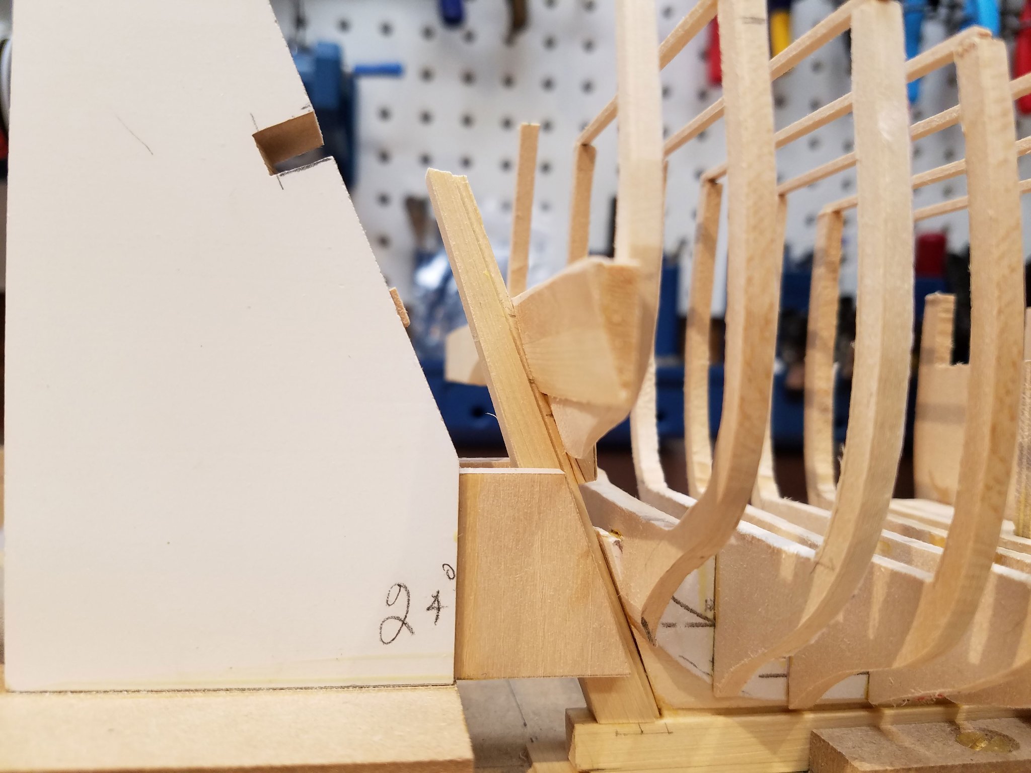
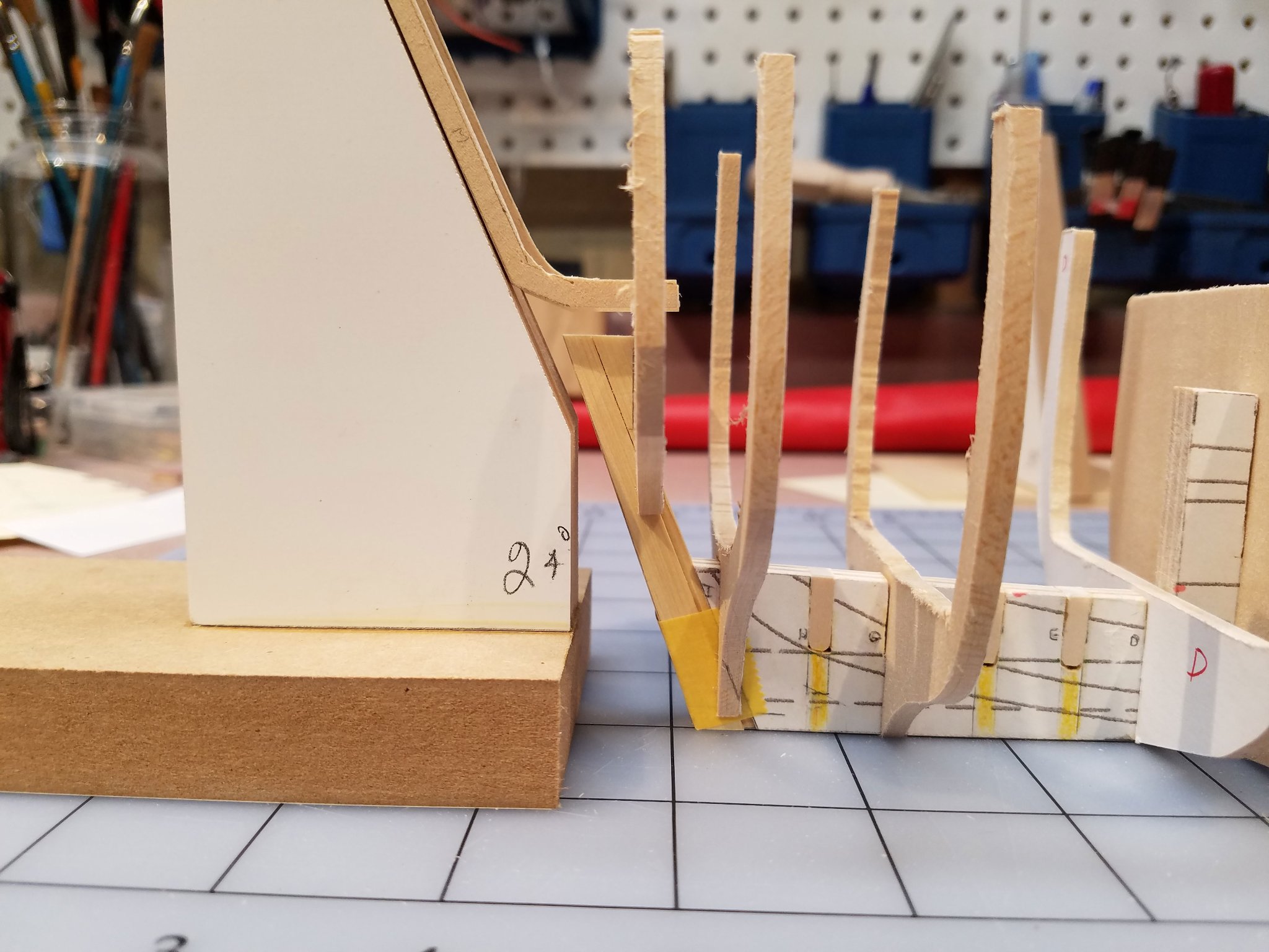
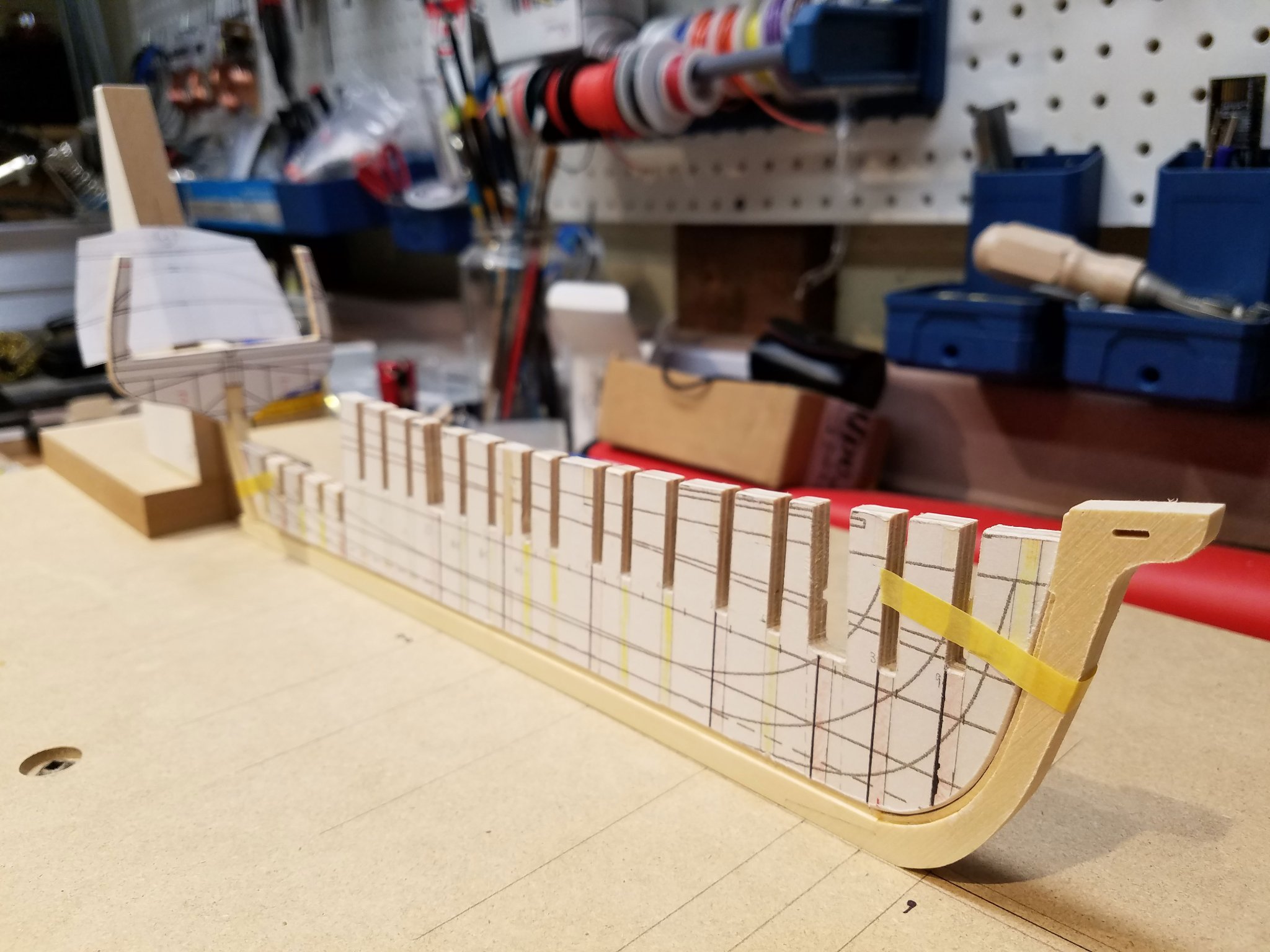
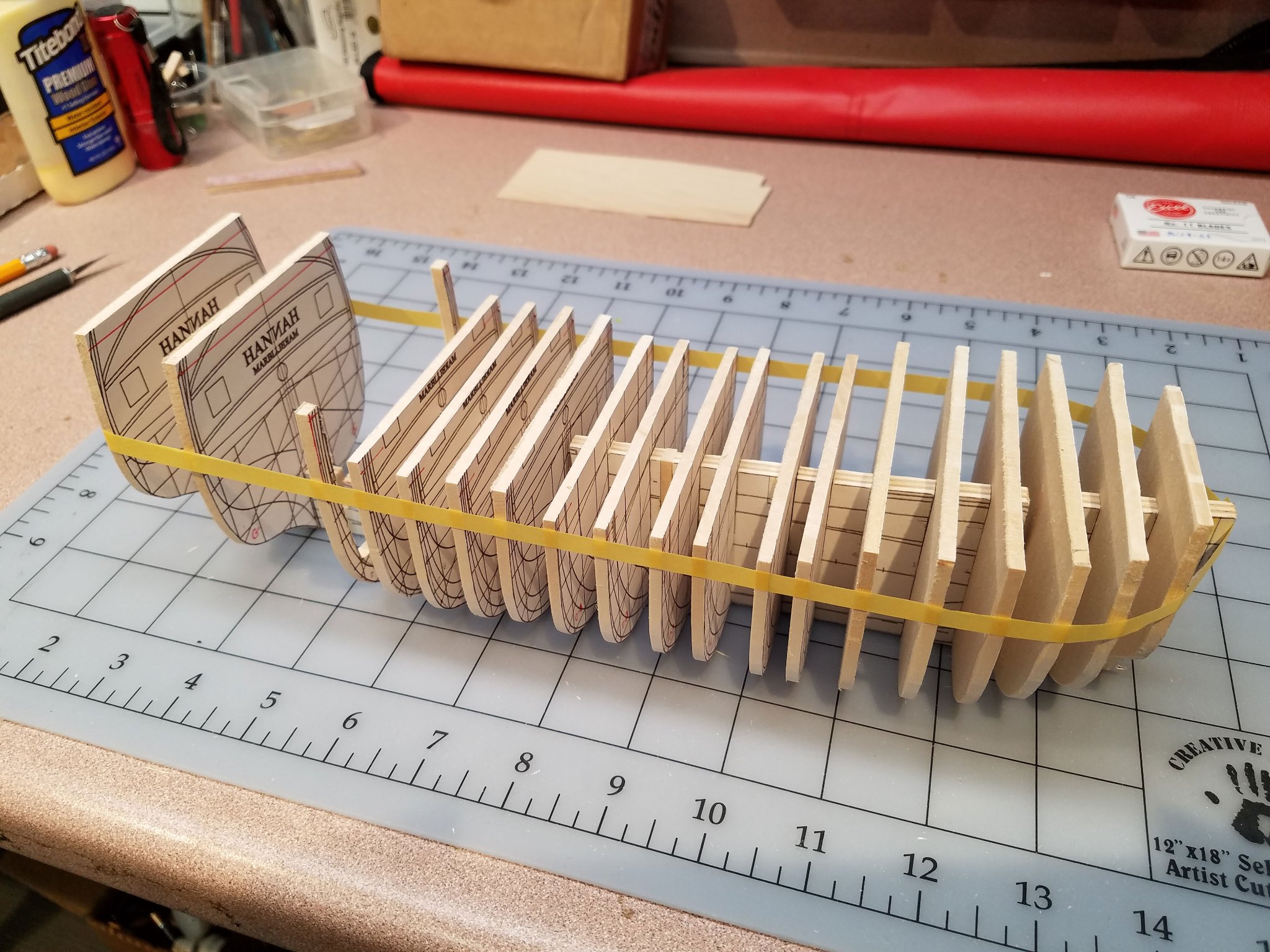
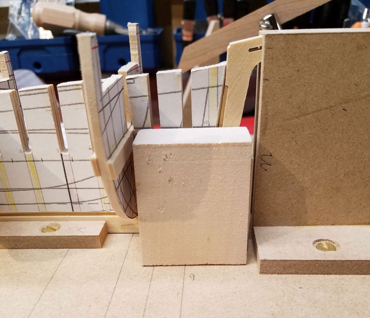
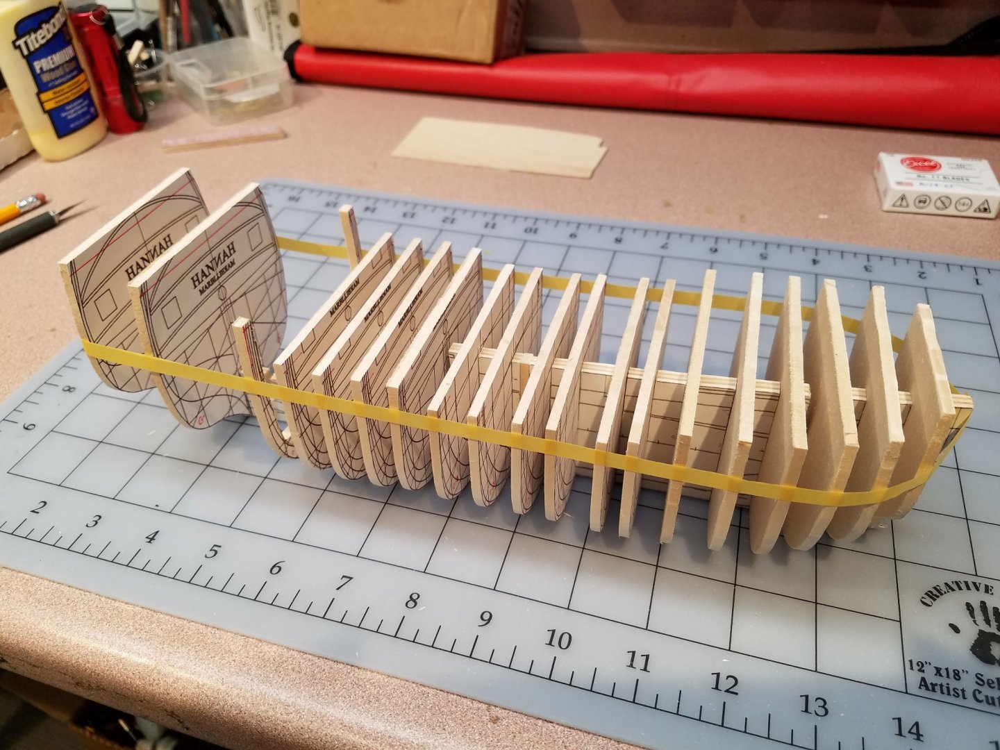
Thank you Lou & Windships . I appreciate the kind words, comments and the likes. I've been able to catch up a little. Using some left over 3/4" MDF, I put together a work table/alignment jig. This shot shows a station bulkhead that is also in line with the location of the foremast. That bulkhead has the usual lower slot for assembly to the backbone as well as an upper slot for the mast. That leaves only about 5/8" in the center holding it together. So, it is cross braced with 1/16" bass to strengthen it. The large block is cut to the level of waterline 3 and is used as a gauge to check the bulkhead heights/alignment. Finally... a little glue! Most of the bulkheads are in and stiffeners were place between them to get ready for sanding the deck and fairing the bulkheads. The curvature of the deck is just about done. Sanding the end grain of the basswood was torturous so I switched to my scary sharp (3/4") chisel which work great and.. no blood on the table! There was even a (lucky) secondary benefit in using the larger chisel in that I could bridge the 1/2" space between bulkheads to smooth the pitch angle from one to the next. The deck timbers are still oversized so I'll have to go back later & finish the top of the deck frames once the timbers are cut to shape. The deck height allows for a 1/32" false deck plus the plank thickness. The backbone and stem are fixed in place while the stern fixture is adjustable (in/out) while still holding the sternpost vertical. The fixture helps me visualize how to blend the last few frames into the outside stern board timbers. It's hard to see here but the stern board is rounded out about 5/32". Mike

-
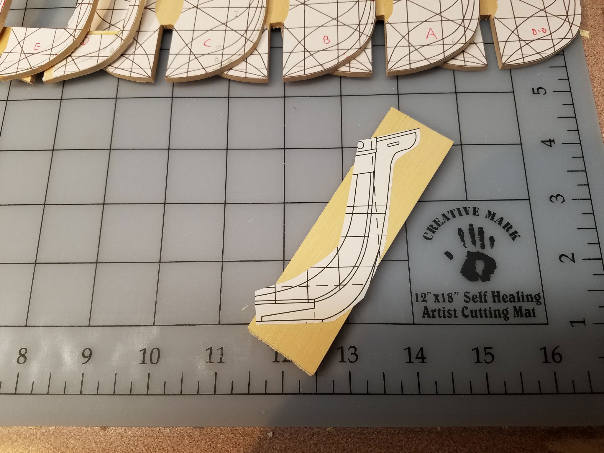
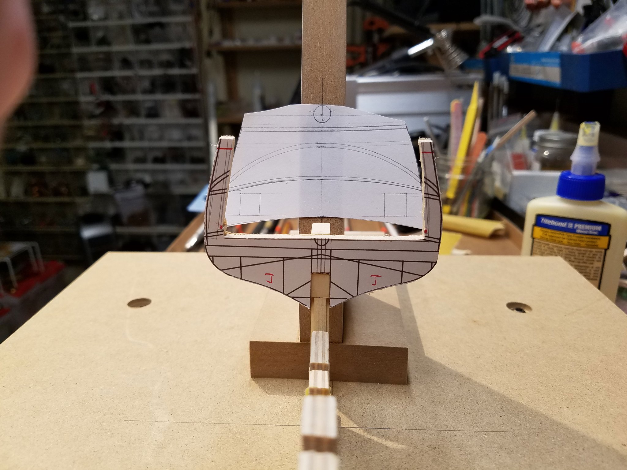
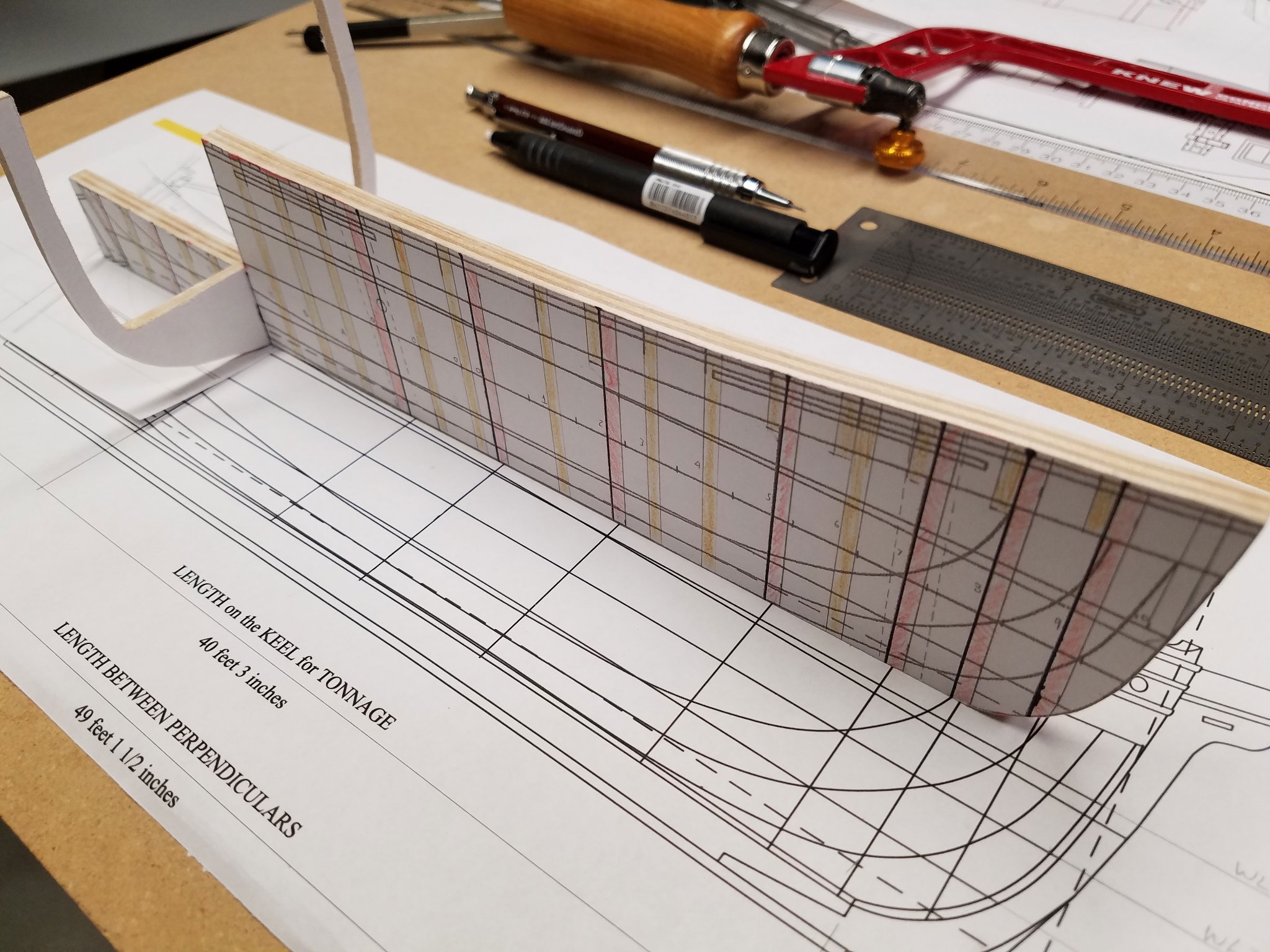
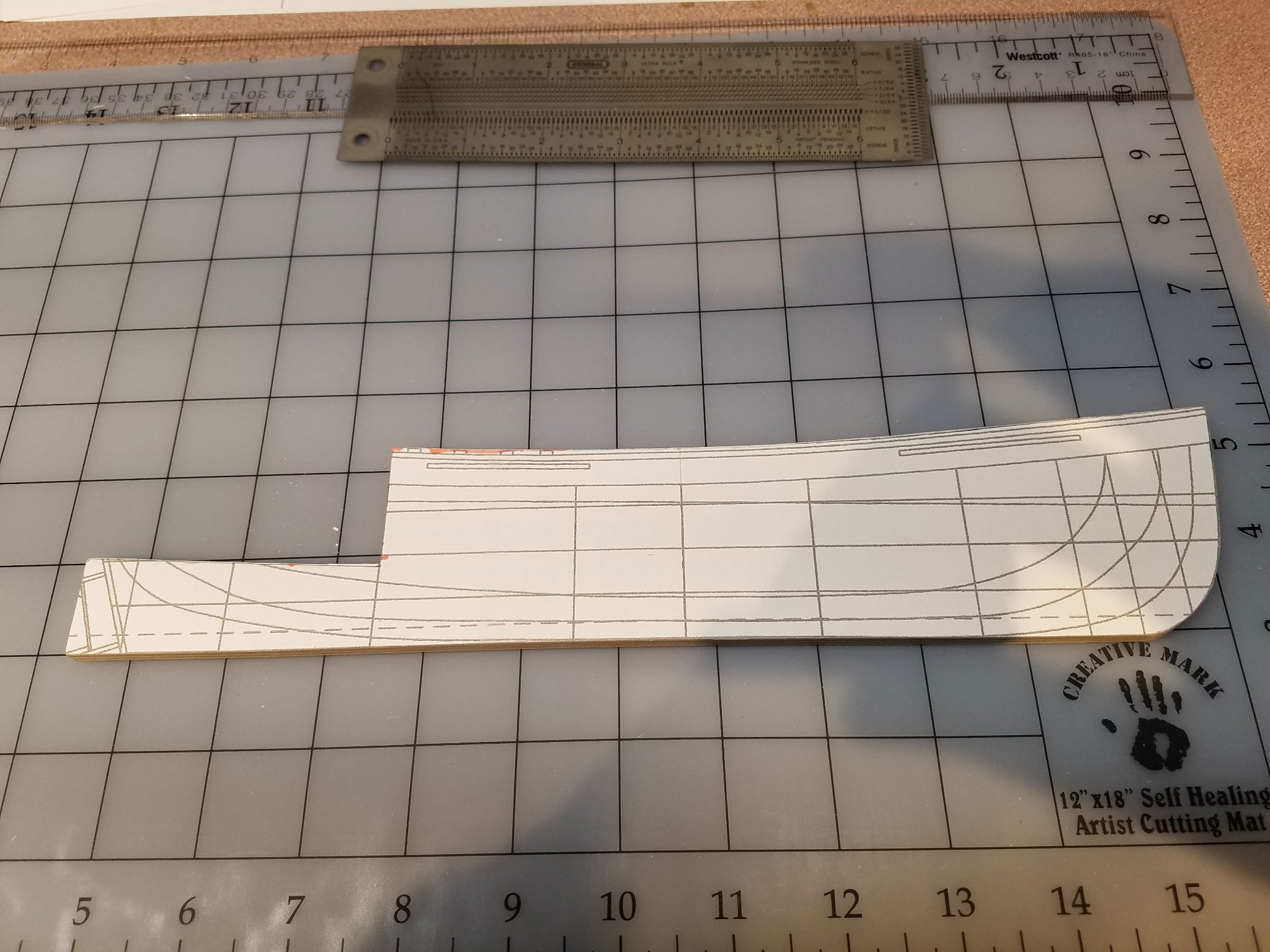
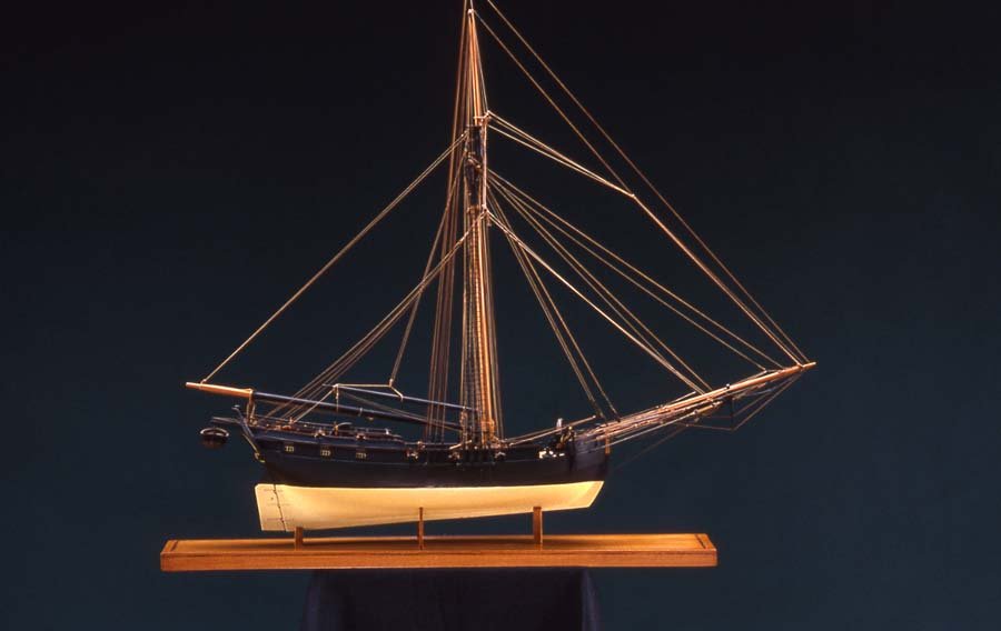
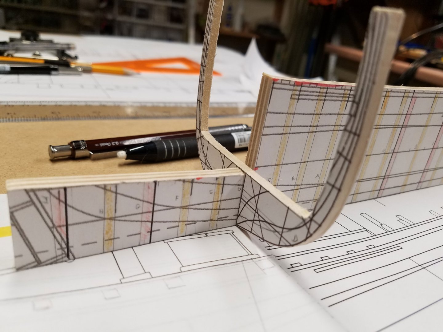
I have finally used a little glue... big step. This is my first scratch POB build and I really can appreciate now how much thinking and planning goes into a good POB kit. @Windships plans have trued out nicely and the monograph has a lot of detail for the build. Of course, I still have novice questions and @Windships has been a big help. The plans are published by the Nautical Research Journal and designed by Randle Biddle. They are available to NRG members for download. Most of the interim time spent since the last update has been working in the area between the last full aft frame and the stern board. The Great Cabin is a focus area so I would like to push the aft wall of the cabin back as far as possible without weakening the framing structure. I settled on using the sternpost to mount the last frame. The height of the sternpost will be set to accommodate a sill just below the two stern lights. The sternboard frames (set high in this photo) will straddle the sides of the sternpost. The keel is not attached yet so the final height of the post is not finalized. The stem requires a Scarf joint. Alaskan Yellow Cedar will be used for the keel and hull planks. As of this moment, I'm favoring painting the hull. The stem was roughed out with a band saw and finished up with a sanding drum in a drill press. This shot shows the lip for the position of the last frame. The rabbet in the keel and sternpost was cut in on a table saw. The stem rabbet was built up with 1/8" x 1/16" strip. This hull has a boxy shape to it so there is a minimal bearding line chiseled in at the stern. The paper stern board is an orthogonal projection from the body plan... my first since the days of bamboo slide rules.🥺 The plywood backbone forward of the quarterdeck is trimmed down to allow for a 1/32" false deck and 3/64" deck planking. Frame "J" will be the aft wall of the cabin. This shot shows the position of the stern lights. There are only two and are spread wide to comport with an 1801 watercolor of the schooner Raven, built at Salisbury Mass, 1786. The bulkheads are yet to be glued in. A few clothespins are the only thing holding things together for now. The counter is very small and just allows enough room for the rudder post. The frames are still loose and extra tall and wide for now with the red lines indicating the bottom of the cap rail. Please comment and/or correct any time, and thank you for the likes and encouragement. Mike


- 75 replies
-
- 10
-
-
Super work on the cages for the deck section. Very clever. Mike
-
Superb, as usuual. If I were a duck, that's the cage I'd want! What wood did you use.... Cherry? Mike
-
Thank you gentlemen for the likes & comments. @Windships Yes, the bow will need some strength to handle the plank curves. And above the wales, I'm looking at cherry & castello so not quite as easy to bend as the bass and AYC. The station shapes aft of "D" are on hold until I settle on the floor (eye) level in the cabin and rework the slots in the backbone. The current slots (filled in now) were too deep and made a loose fit with the bulkhead slots. If the cabin floor comes up a bit, the bulkhead slot can be deeper and get a better grab. For the cabin area, regular (thick) POB framing is too thick to allow for maximum space. So for frame "I" aft, I'll need to work out a more traditional plank on frame layout. I've got David Antscherl's TFFM for help. Great books! The cabin floor sits just below WL2 and pitches up just a bit toward the stern leaving enough gluing area of the sternpost to the backbone. The floor level as shown seems to need more pitch for looking out the port. I'll probably raise that more toward being parallel with the quarterdeck. Shot of the stern with a temporary sternpost and keel. Shot of the Great Cabin floor at it's current level.

-
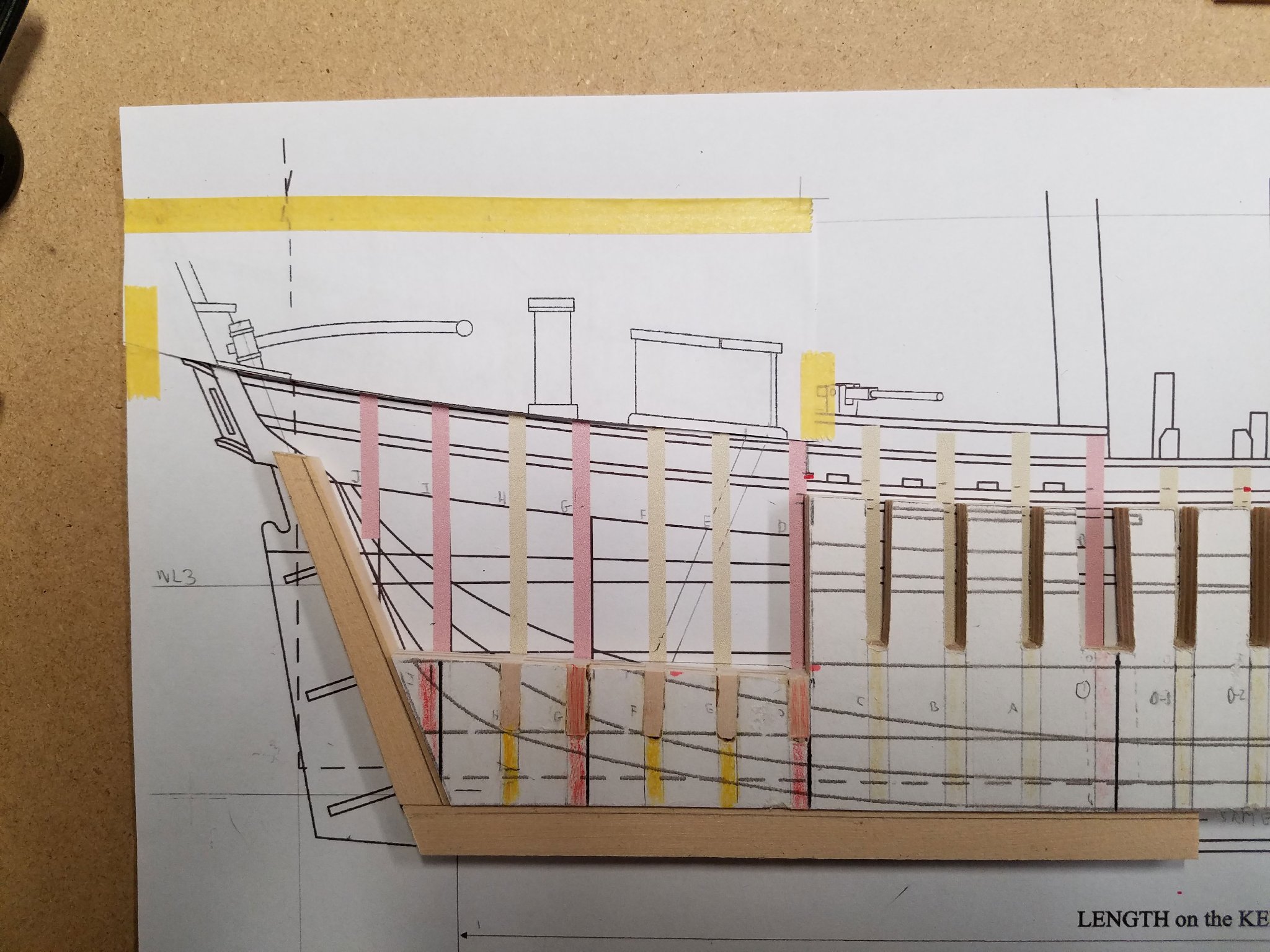
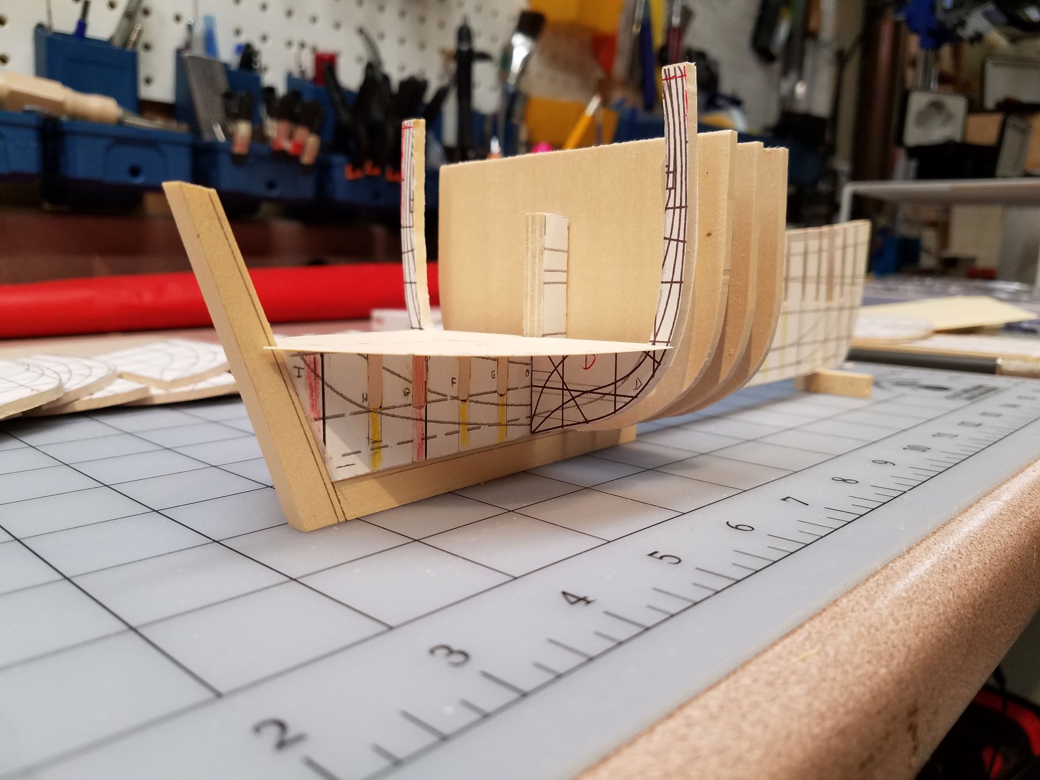
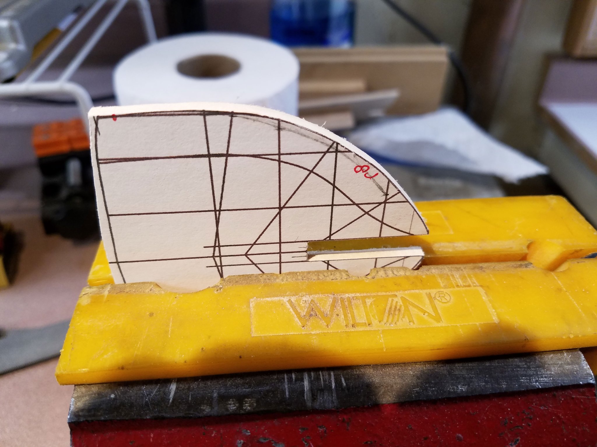
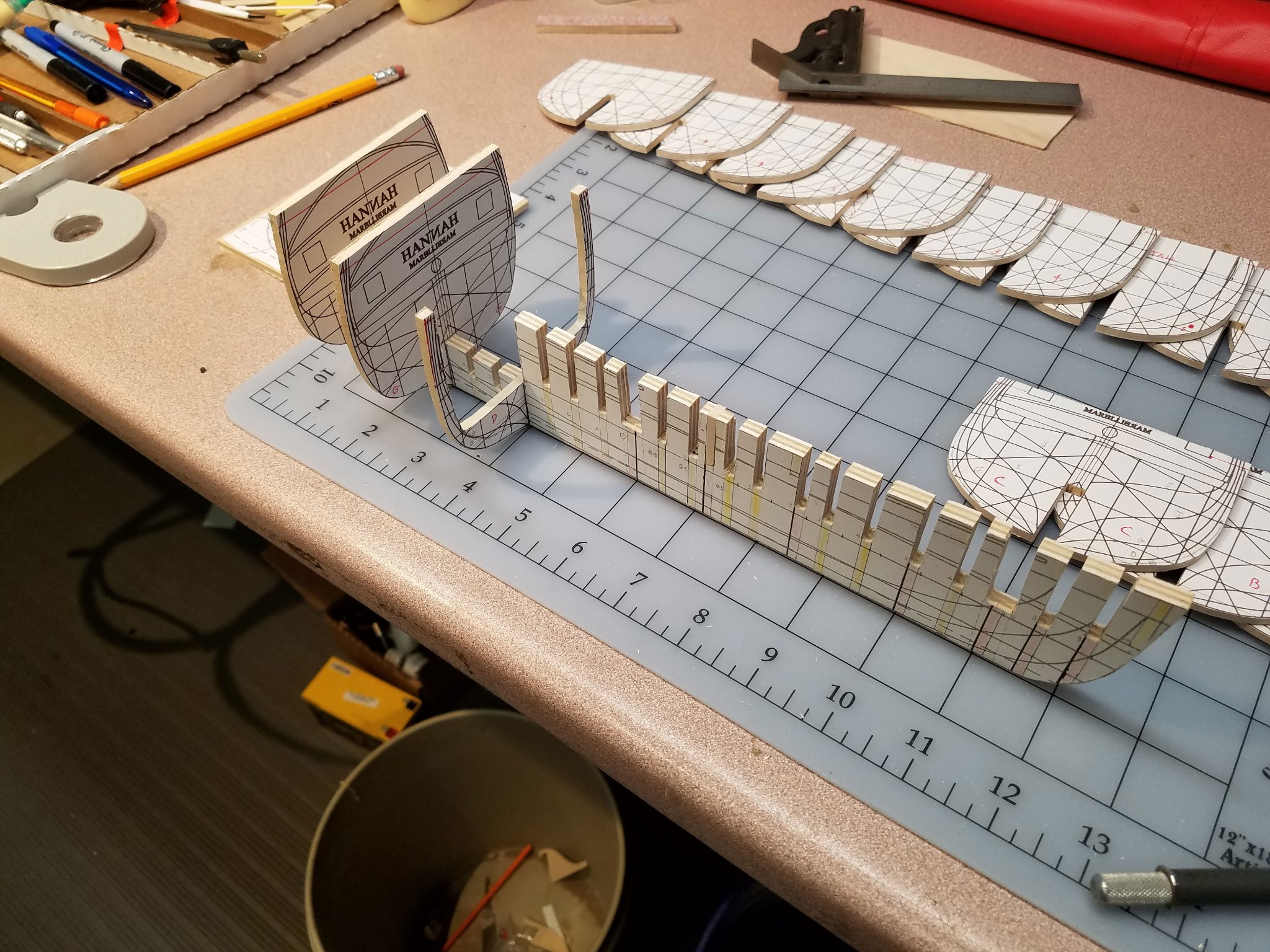
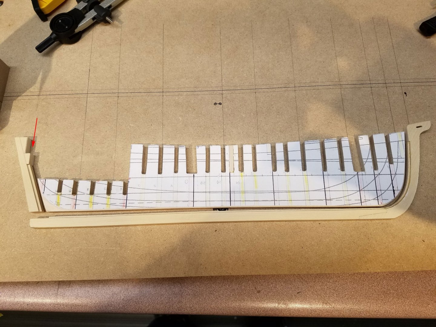
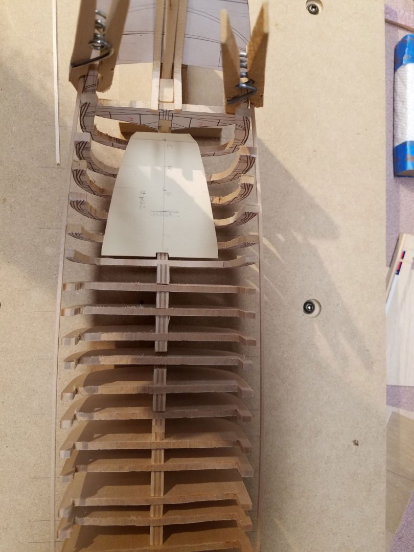
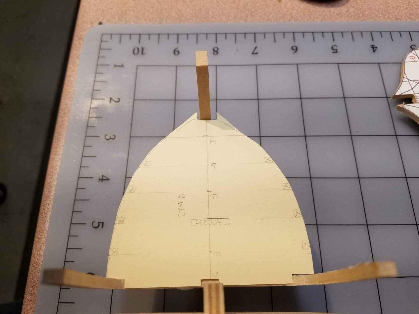
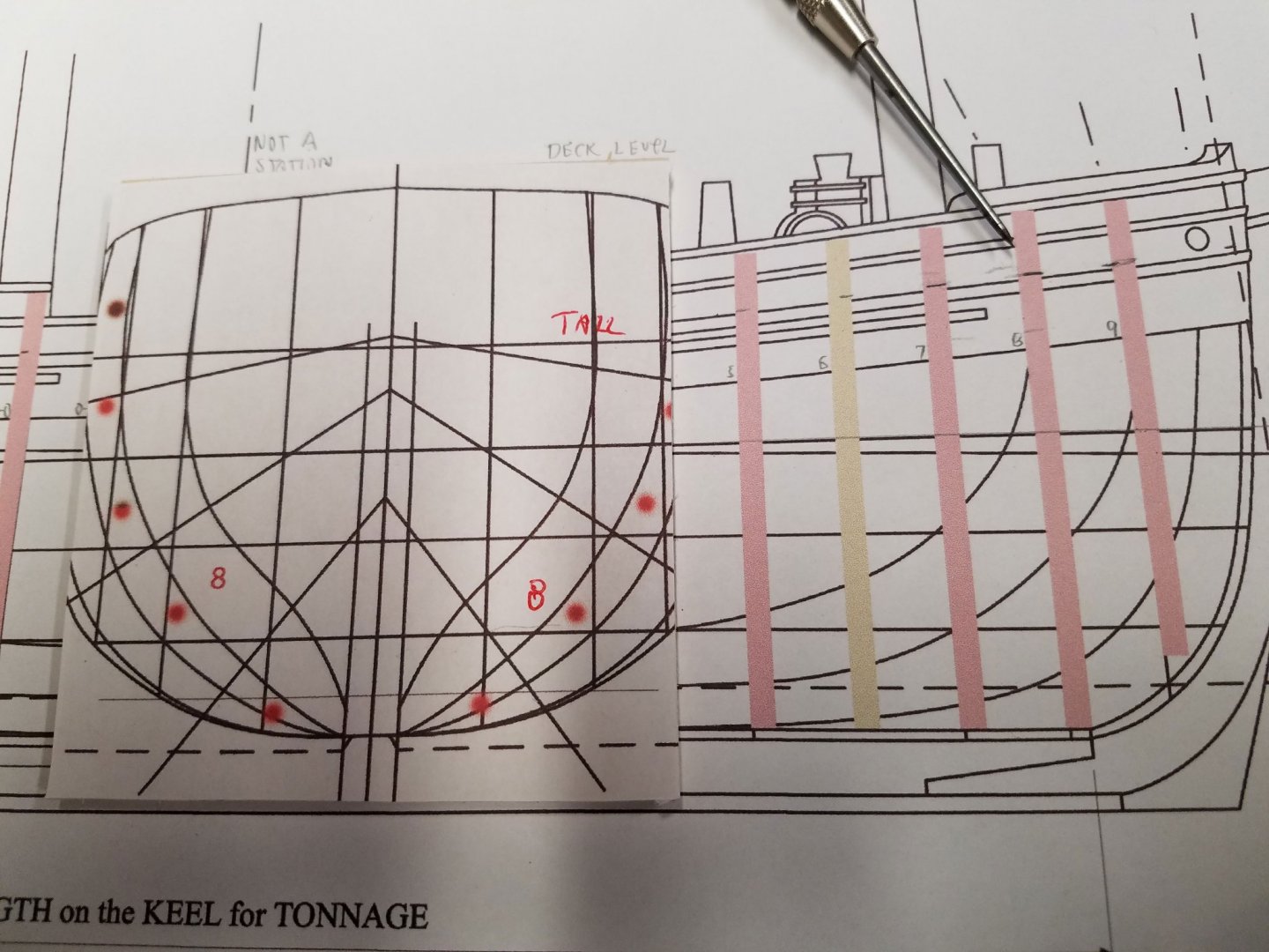
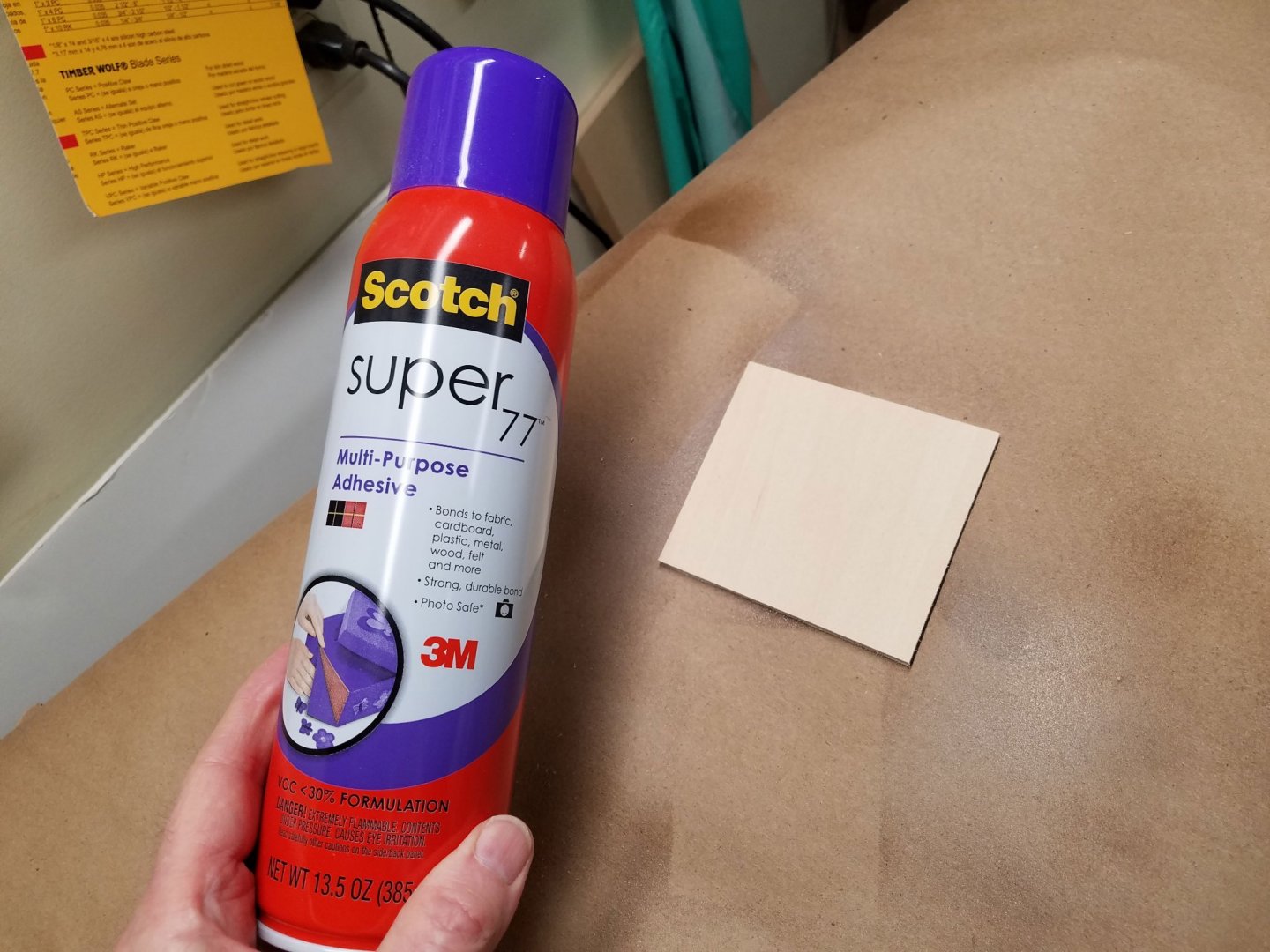
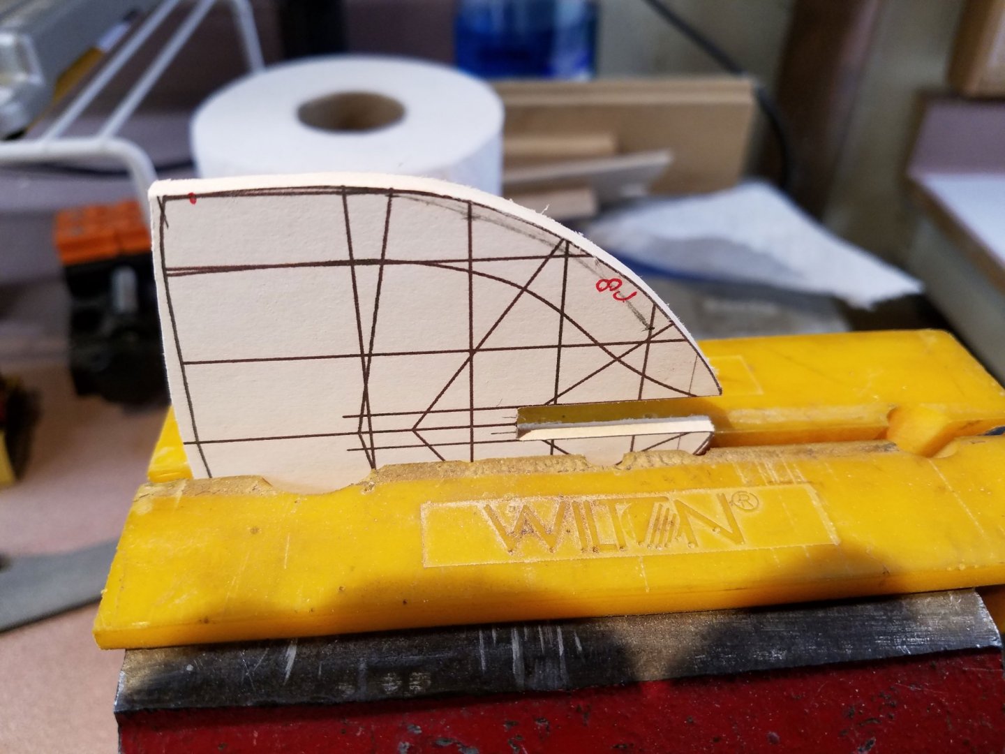
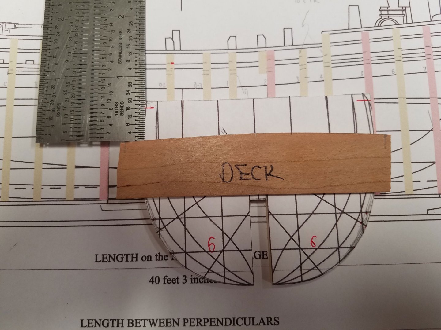
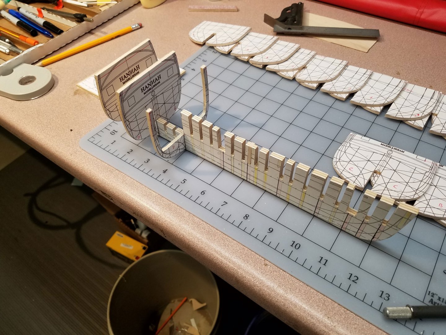
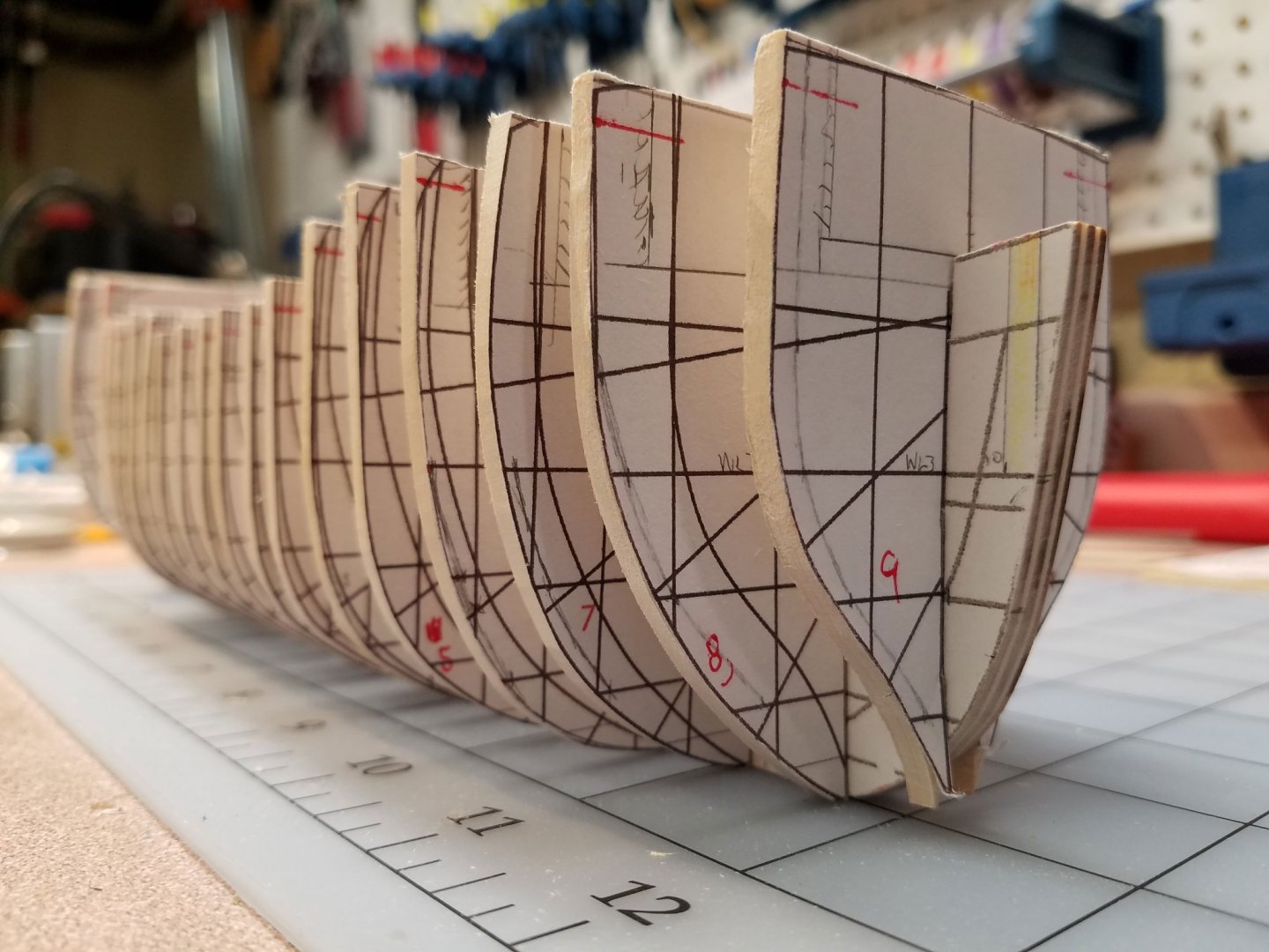
Saw dust, finally!! I'm unfamiliar to scratching the POB backbone so a lot of the time since the last post has been used for planing the deck levels to accounts for the deck and false deck thickness, etc. In my previous post, I hadn't yet thought about that so I have since trimmed down the top of the back bone, and made a new #9 bulkhead to account for a false deck forward of the quarterdeck. This is a small model but I'd like to show all the deck timbers as well as the Great Cabin area. The timbers are only 6" x 6" so with that in mind there will be about 22 1/8" basswood bulkheads used. The spacing, for the most part, is 1/2" with some exceptions in spacing to allow for the rise in the fore deck and for the gun supports. Of the 22 frames, 10 are at an actual station location, the rest will be lofted or just placed and sanded back where needed. Again, I've been following the builds of @tlevine, @JpR62 and @KenW for planning which has saved a lot of do-overs on my part. The general process for the scratch bulkheads I used: The plans are published by the Nautical Research Journal and designed by Randle Biddle. They are available to NRG members for download. In this shot, the bow body view was cropped out and mirrored in a photo editor. Four of these views were grouped at a time and printed on a 8 1/2" x 11" sheets of paper. Each station, in this case #8, can be highlighted as well in the editor if needed. For gluing, I intend to remove some of the template paper so just lightly sprayed adhesive used to attach the bulkhead template: The frames are rough cut on a band saw and, for the 10 station frames, disk sanded to the ink line. Other frames are lofted if there is a significant bevel (bow & stern) or left a little outside the ink. Using waterline 3, the height of the deck timber was marked exactly and cut 1/8" higher sized to allow for sanding. The deck curvature was drawn in using a template at the height of the plywood backbone. Originally, I had planned to work on the Great Cabin first. After seeing other builds, I realized the remainder of the hull would probably be needed to support and align the transom area. Note the slots in backbone in the Great Cabin area are to be filled in. There is too sloppy a fit with the bulkhead using that cut out method. There will be just one longer slot in the bulkhead with a snug fit. Water line three is used as the reference for the fit. Note that top horizontal line is not a waterline. Some bevel lofting is shown shaded on frames 7, 8 & 9 along with the deck levels marked out. The bow curvature is very steep so another bulkhead or filler is planed for the bow (yellow). Only 4 more regular frames to go but I was itchy to get a 3D look at Randy's Hannah so I dry fit and taped what I have so far: I'm stalling a bit before cutting the basswood down to the deck levels in case of something unforeseen. Any help on that is welcome. Please comment any time, and thank you for the likes and encouragement. Mike
-
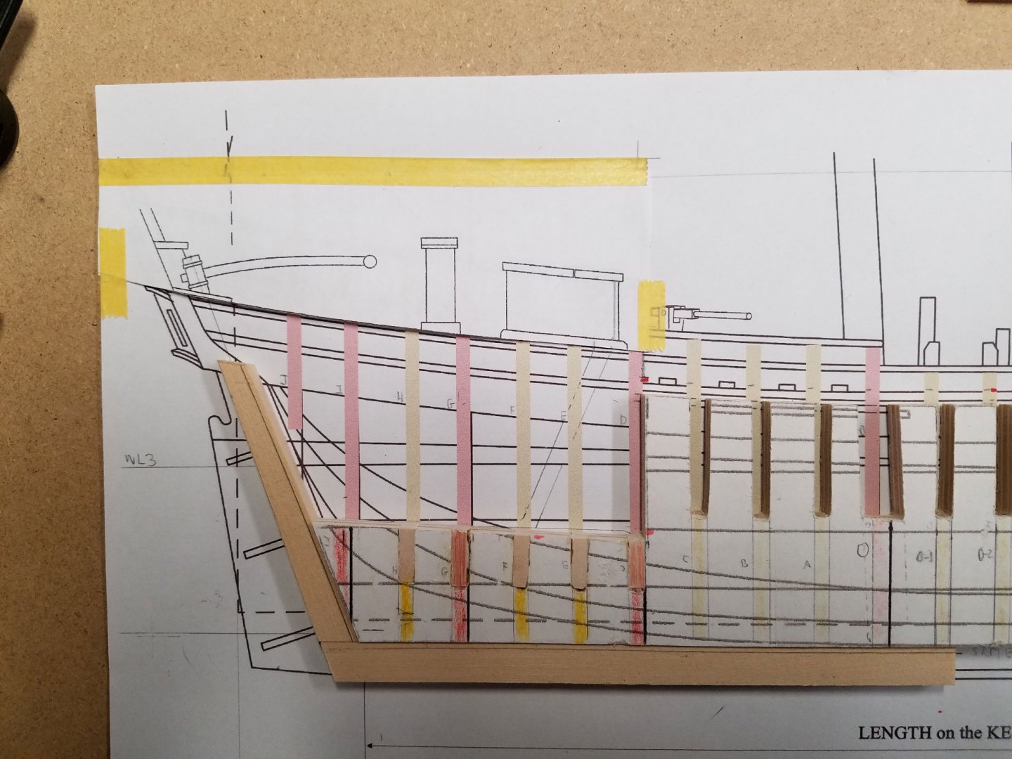
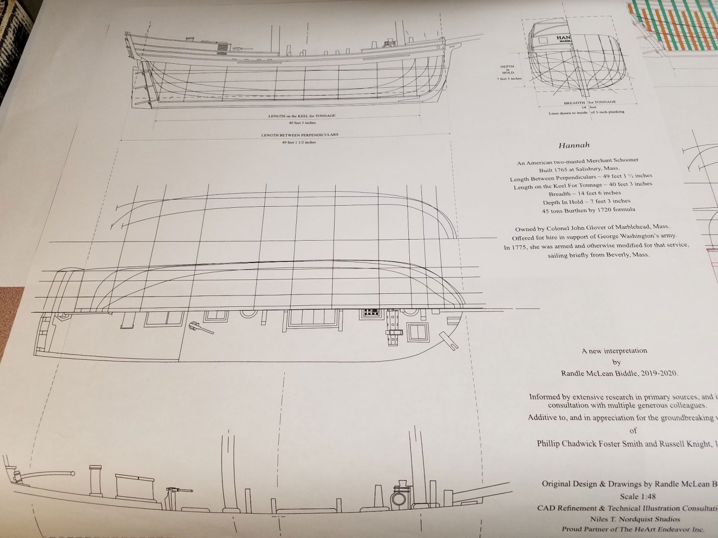
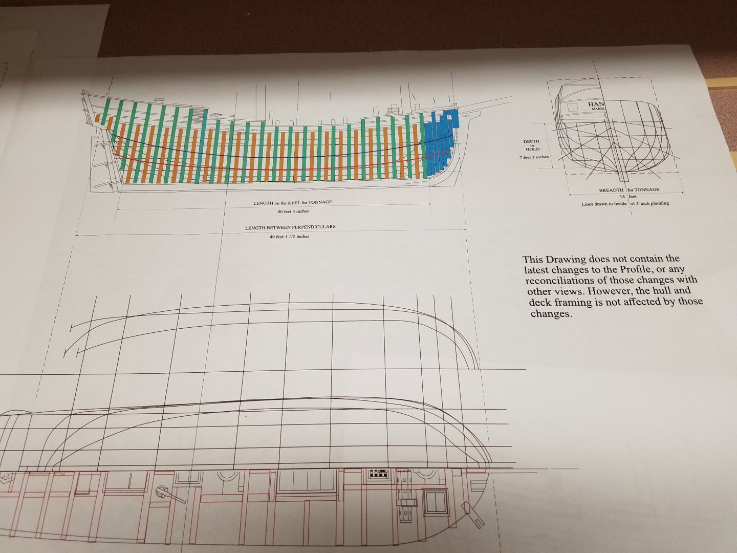
Some progress has been made on Randle Biddle's Hannah since post #1. Decisions made, wood ordered, books ordered and even a little sawdust created. I've been closely following @tlevine and @JpR62 especially for their construction planning. The plans are published by the Nautical Research Journal and are available to NRG members for download. They include 5 sheets.... composite, full view, half breadth, body and stern views. The composite plan contains everything I have needed so far. With this sheet alone, I can bring it into a photo editor at full size, crop out any view needed and print it out on one 8.5" x 14" sheet. The lines in all the views I've used from the composite plan reconcile. The stern view in the upper right corner contains diagonals. I don't use that feature but the few points I've checked look good. The "All Views" sheet contains a framing plan that I use for referencing the position of certain 1/8" POB frames. In that I want to use all the station lines plus loft 12 more, the green frames may not necessary line up with the required POB frames. Originally, I was going to go with a 1/4" POB style model but decided to go with a partial open deck look with visible stanchions. The Randle Biddle article refers to the "Great Cabin", which caught my eye, so I have been planning around that area of the deck to be partially open. That being the case, 1/4" POB frames can not fit in the transom area and allow a scale sized cabin area. The backbone is 1/4" plywood cut to deck height along the center line and cut low in the cabin area. This shot shows some marking out for the frame positions. Red frames correspond to existing station positions while the yellow full frames will be lofted. The hull shape is "wide and deep" which I'm sure is the wrong phraseology. In any case, the center four frames are identical and there is very change in them in the central hull area. Dotted lines show the position of the main mast and foremast. Some marking out of the scale cabin area. At this point, I'm unsure of how much deadwood should be accounted for. Two volumes of TFFM are on the way so I hope that helps out. For now, the ladder is set at 25 deg. Only one basswood dry fit frame is attached. It's left tall and wide in the moulded dimension. Some 1/8" AYC is on order. I'll test that vs. the basswood for frame strength. The total amount of plank gluing area with 1/8" frames at this spacing is about the same as using 1/4" frames with wider spacing so, fingers crossed, glue strength should not be an issue. Thanks again for the likes, your input is very welcome. Mike

-
Ken, I meant to mention... hard wound is good if one wants to control the shape a little while soft wound will drape the way it wants.
- 238 replies
-
- 3
-

-
-
- sloop
- providence
- (and 1 more)
-
Hi Ken, I don't see any (what I call ) kinks in that shot. That line looks pretty good to me albeit a bit "hard".... slightly too tight and looks stiff. By "kinks" do you mean the first twists got so tight it kinked into a little lump? What formula (weight of thread, threads per strand, number of strands) did you use to get to .035"? Is .035" the size you want? Did it unravel? Mike
- 238 replies
-
- 4
-
-
- sloop
- providence
- (and 1 more)
-
Lou, did your time zone change? You're up very early! And thanks guys for the likes already. Jean-Paul, your Cheerful is one of the "open" style projects I've been watching and learning about. This Hannah is much smaller in below deck volume the Cheerful so I haven't yet decided how much to try to show. I'll be in the paperwork phase for a while spending extra time reconciling the views, locating small features, ... etc. 'Just trying to understand where bulkhead support might be needed or get in the way for that matter. Mike
-
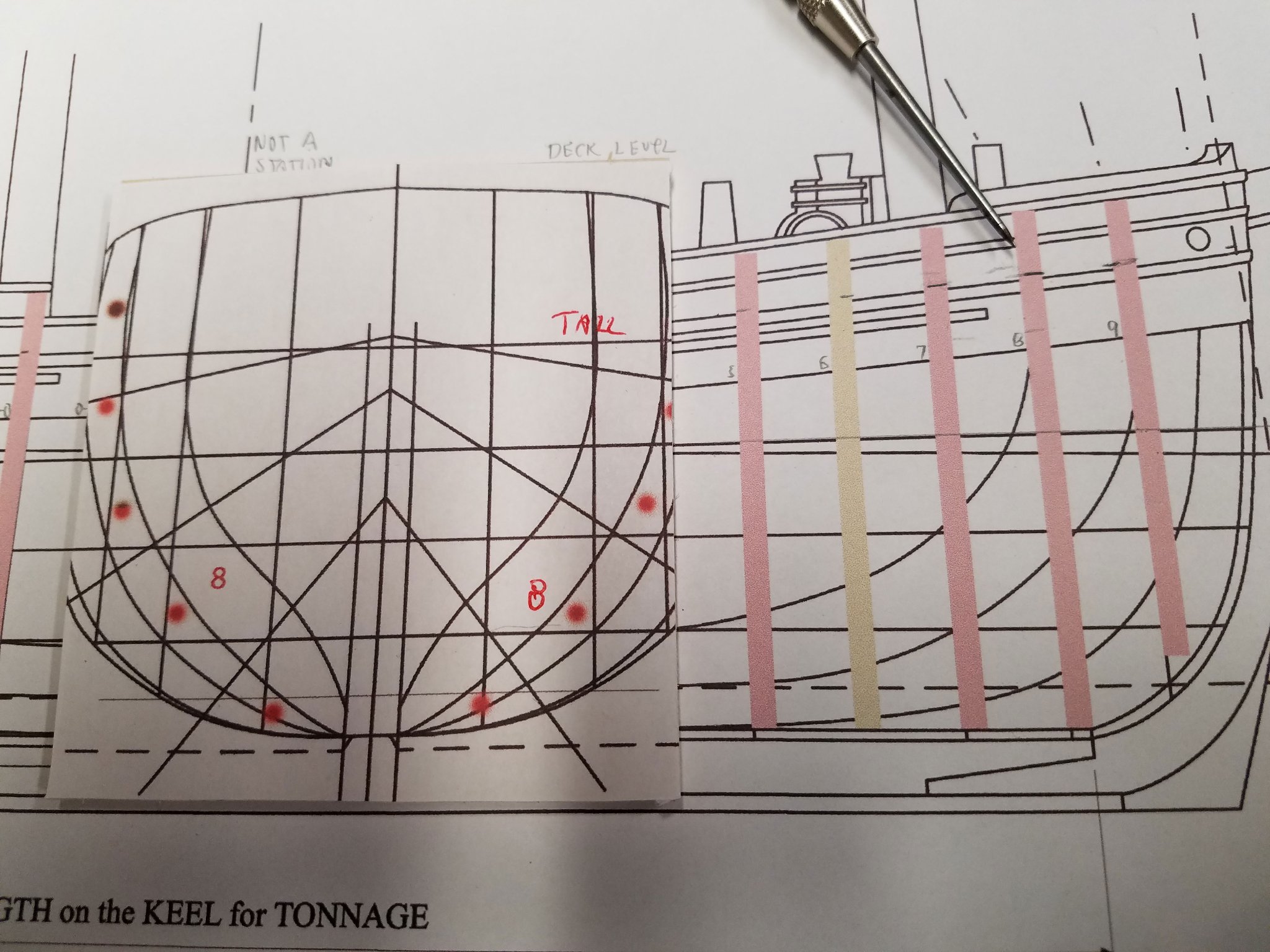
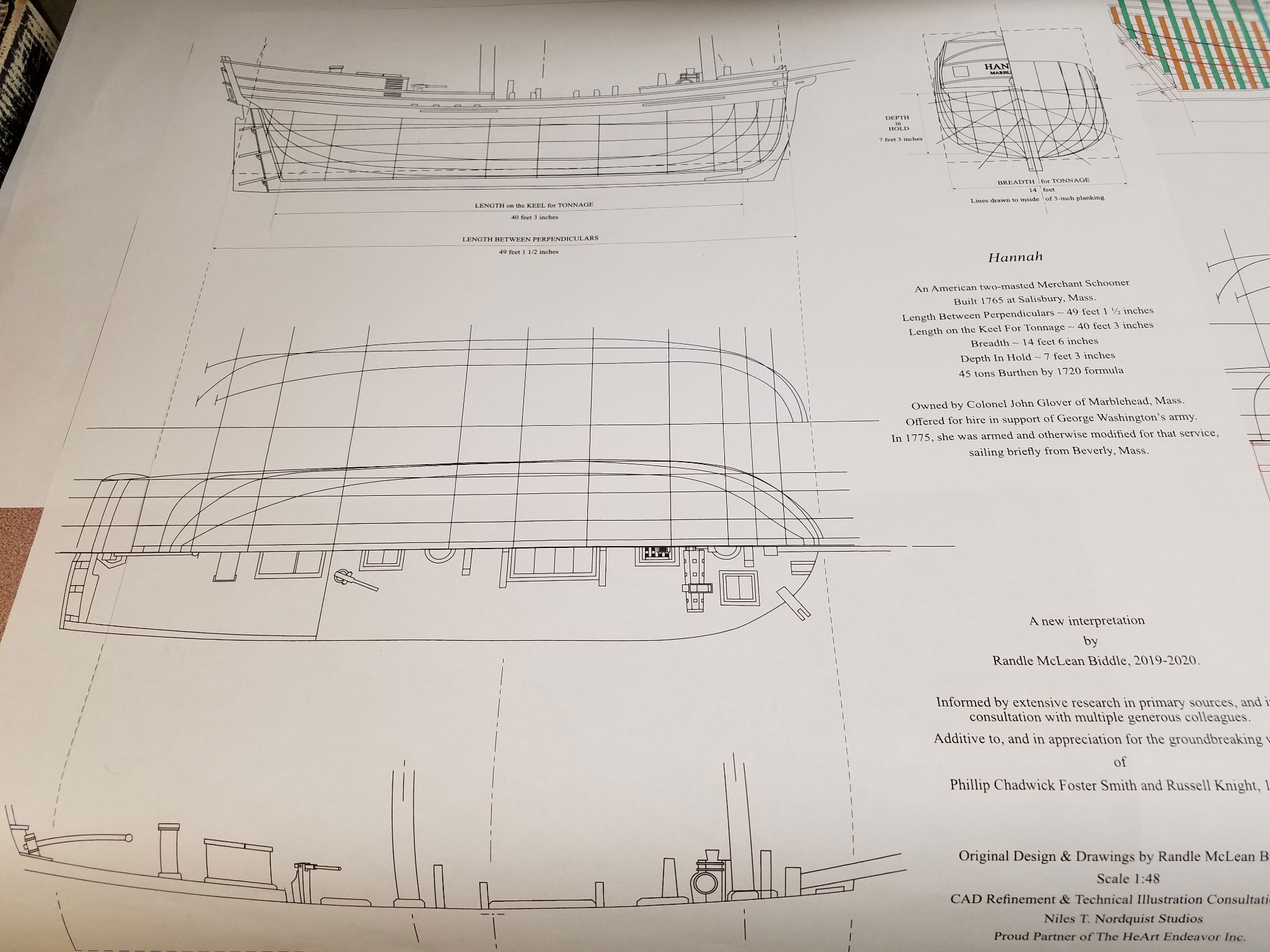
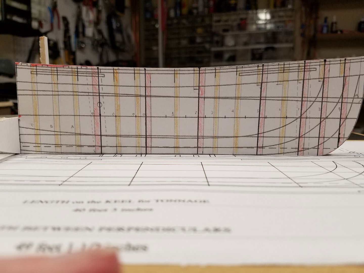
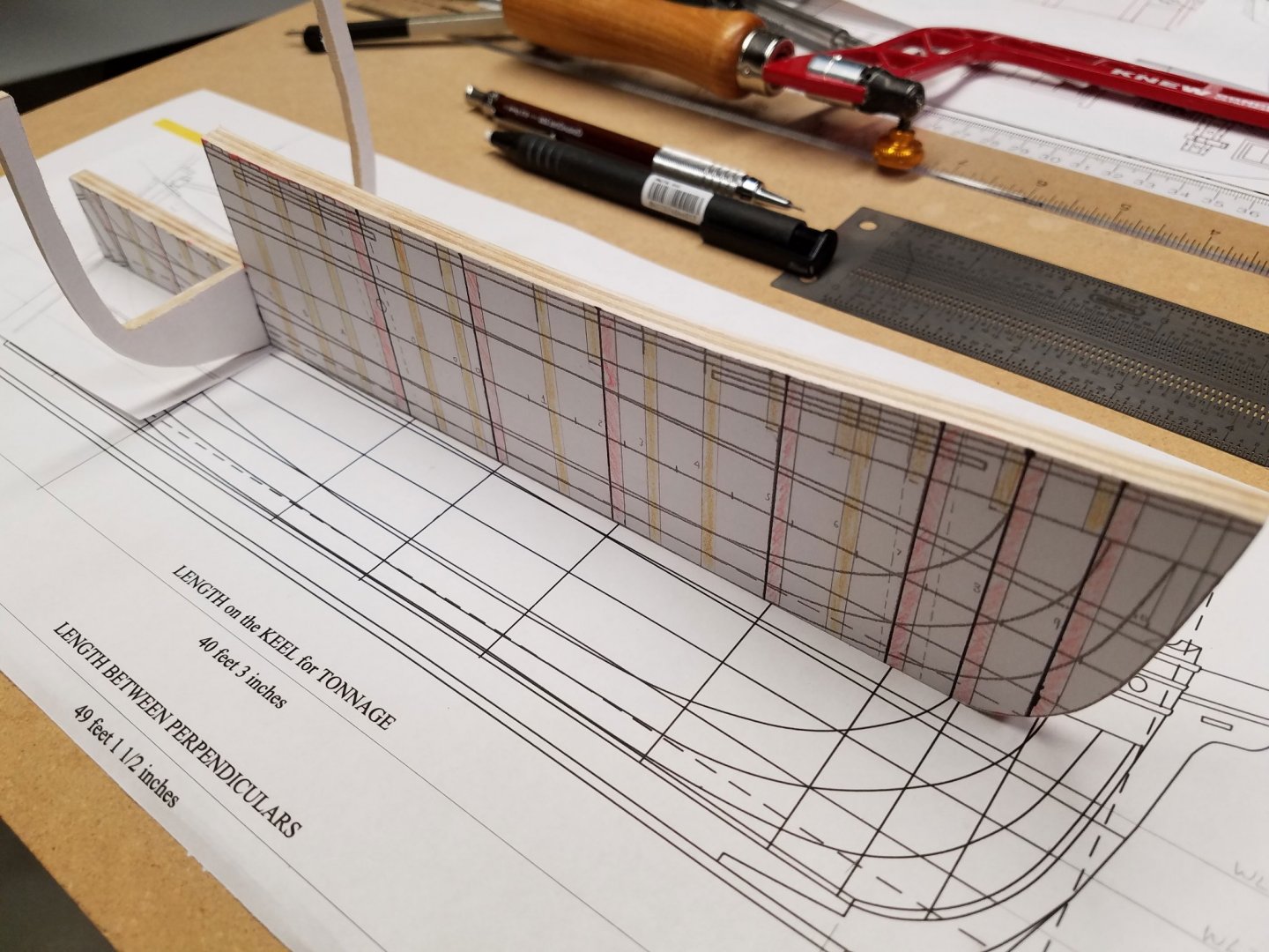
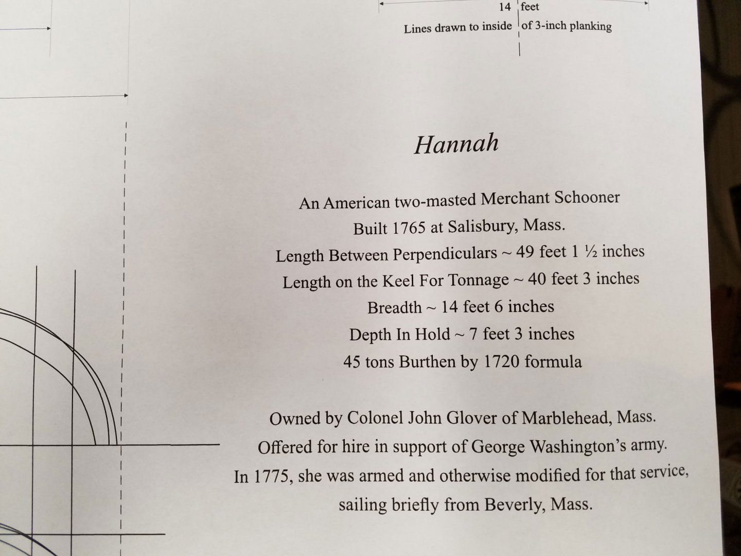
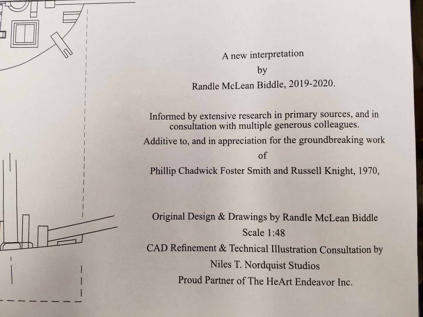
Recently, I became interested in ships of the Colonial era. From a forum post about Chaleur I came across a lead to an extended article by Randle Biddle at the NRG. It discusses a his new design perspective about the Hannah. I found the article very novel and well thought out and it will be a great model project for me albeit a challenge. The article also includes plans by Randle Biddle: The plans are published by the Nautical Research Journal and are available to NRG members for download. That’s a great bargain and well worth the cost of joining the NRG. The plans consist of five sheets at 1:48 scale in jpeg format. I chose to upload four of the sheets to Staples blueprint service and they were ready the next day and look great. In a photo editor, the body plan was cropped into bow and stern half views then each mirrored and stitched back together to duplicate and cut up for station templates. This shot shows the significantly lower tonnage then Harold Hahn's plans. This will be a 1:48 scale scratch, plank on bulkhead model. I’ve seen some really great open-deck model versions and want to give that a try. This remarkable project by @tlevine of the Swallow 1779 will be a great resource for me to get through the planning pitfalls that I’m sure are coming my way. Comments, corrections and "watch out fors" always welcome. Mike
- 75 replies
-
- 10
-
-
Beautiful display John. There's a lot of work put into that seemingly little kit. Next? Mike
- 104 replies
-
- 2
-
-
-
- model shipways
- new bedford whaleboat
- (and 1 more)