HOLIDAY DONATION DRIVE - SUPPORT MSW - DO YOUR PART TO KEEP THIS GREAT FORUM GOING! (89 donations so far out of 49,000 members - C'mon guys!)
×


bricklayer
-
Posts
66 -
Joined
-
Last visited
Content Type
Profiles
Forums
Gallery
Events
Everything posted by bricklayer
-
RAL colour chart: https://en.wikipedia.org/wiki/List_of_RAL_colours#RAL_6000 The lower the L*% value in the CIELAB 1931 column, the darker the actual colour. L* is perceptual lightness. Looks like you don`t build a boat for the first time Michael
-
Hi Keith, you`d better lock the door of your workshop before eye-surgery and keep it locked until you`re recovered. If you don`t, then your wife might enter the room to continue the steam yacht build. And you`ll become unemployed or have to do housework. Change of roles ☺️ Michael
-
Hi Keith, one off-topic question: I noticed a sheet metal cover at the front edge of the mill`s table. Is there a glass scale or magnetic scale attached underneath the cover? about the forthcoming surgery: It`s going to be alright. I`ll cross my fingers. Michael
-
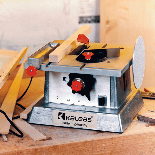
@Wefalck, the Böhler mini circular saw table is still availiable. It`s the brand that changed, only. For a couple of years the brand of former Böhler mini tools is Kaleas. https://www.kaleas.de/en/modeling-tinker/minitool/72/minitool-table-circular-saw On ebay UK ther`s a seller who currently offers the saw for 179 GBP. The die-cast body isn`t a beauty but it looks rock-solid. It may make sense to buy the saw, only, if one already has a 12 V DC power supply @ bruce d I don`t own or use that table saw. So I`m awaiting your review. Michael
-
If you buy cheap then you`ll buy twice. As a beginner I had bought the tiny toy saw KS 230. According to it`s specs it was sufficient to me. But the surface-milled aluminium table is as flat as the plastic cabinet is. It`s convex. So the fence doesn`t lie tight on the table on it`s entire length. Towards it`s free end the fence lifts and there`s a gap between table and fence. Thin stock slides underneath the fence. The fence doesn`t run parallel to the blade. I didn`t find away to adjust it. The motor`s torque is poor. The 50 mm blade has 6 to 8 mm clearance but the saw does hardly cut 3 mm birch ply. After having gained some experience I bought the FET. This tool deserves the name circular table saw. It cuts 20 mm fir and 12 mm beech and doesn`t complain about the job. The fence is rigid, parallel to the blade and tight to the table. The saw is versatile. It can be used for various applications The FET cuts voluntarily rather than being obliged to do so. My conclusion: If you can`t afford a + 300 € saw instantly, then better save your money until you can afford it. Cheap tools work properly? That`s wishful thinking. Though there`s exceptions from the rule. Michael
-
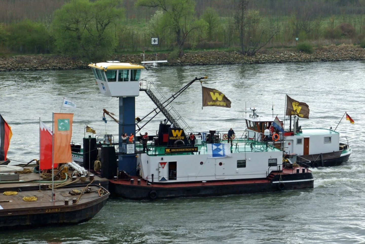
Hello Brian, hi all I´ve seen towboats on the Rhine. They tow two to six barges, only. Unlike the Mississippi towboats they have elevating wheelhouses to adapt to limited clearance of bridges across the river. https://de.wikipedia.org/wiki/Schubboot#/media/Datei:Buran.rhein009.jpg I`d like to see a continuation of your build log, if you don`t mind. Michael
-
Hi Tom, it sound like there`s some tedious work ahead. Will it pay off in terms of visibility? Will anyone notice that the fasteners are three piece compounds? Actually more than three pieces per fastener if each strand of copper wire is considered as a single piece. At least I`d replace the twisted copper strands by a solid brass rod. Twisted wire doesn`t represent a thread at all. The diameter/pitch ratio doesn`t fit. The diameter/pitch ratio of a regular M6 screw is 6/1. There`s no way to twist strands of wire that shallow. My point of view: Too much effort for an almost invisible effect. Nonetheless I`d like to see a sample of your suggested fasteners on scrap wood. I don`t mean to disencourage you. Michael A coil spring would represent a screw thread. But it`s way too large to pass the bore of the 0.5mm tube.
-
Size of a printer needed
bricklayer replied to Frank Burroughs's topic in Modeling tools and Workshop Equipment
Hi Frank, some inkjet-printers aren`t limited to standard-size paper. They print A4 size (210mmx297mm) and custom size (up to 216mmx1200mm). 1200mm equals almost 48". So the length should be sufficient for most purposes and there`s hardly a need for print-services. The only tricky thing is to find a source for a spool of 210mm or 8.5" paper. Michael -
Claire, swap rear and front of the sheer strakes. At the bow those holes make sense. In the picture the planks are still wet. Let`s hope that you havn`t glued them, yet. Michael
- 39 replies
-
- 3
-

-

-
- Lowell Grand Banks Dory
- Model Shipways
- (and 1 more)
-
Hi mj, it isn`t your mistake that the portion of the hull next to the bow is too pointed, too straight, doesn`t have enough curvature. There should have been an additional former between the stem and former #1 to provide a proper shape of the hull. It`s an issue of kit design (saving wood). Nonetheless the finished hull looks good to me. Better than most first time builds. And you`re incredibly fast. Do you want to row the Whitehall on a lake on easter? Michael
-
Hi MJ, another book suggestion to add to your tiny library: "Building Classic Small Craft" by John Gardner. I bought it a couple of years ago and I wouldn`t want to give it away. Never ever. Different types of working, fishing and leisure boats are described and depicted in detail. The book contains brief or extended history of each type of boat, linesplans, dimenions of timber, fasteners, tables of offsets, conversion of rowboats into sailing boats, other modifications and alterations. The Whitehall and the Peapod are just two of over 40 boats that this book deals with. It`s two volumes in one book. I`d call it a comprehensive one. Michael
- 23 replies
-
- 2
-
-
- boston whitehall tender
- rowboat
- (and 3 more)
-
Sections, at least the ones I´ve seen, are always perpendicular or orthogonal to the plane that they intersect. But if the line B - B was angled, then the intersection would be an angled plane.
-
Hi woodshipguy, on the same or a seperate sheet you`ll find another drawing called "section B". Your drawing shows the x-z plane. "section B" shows a fraction of the x-y plane at a particular hight indicated by the horizontal lines next to the letter "B" The arrows indicate the side of the intersected object, that`s shown in the section drawing. I guess that you`ll see a taper beginning at the bearding line, the dashed-dotted one, ending at the stern post and keel. The taper compensates for the thickness of hull planking so the garbord and plank ends at stern hit the sternpost and keel flush, without recess. I´m familiar with drawings due to my profession. If I wasn`t, then they`d be a mystery to me, too. Michael
-
Rudibob, I`m glad that my previous post didn`t disencourage you. Continue your build in spite of those issues or flaws. Don`t let daylight shine through that gap any longer. That`s all that matters at the moment. I`m still convinced that the curvature of the stem piece is right and the curvature of the adjacent false keel is wrong.
-
Good morning Rudybob If you request a replacement part then you`ll get a new part that looks exactly like the one that came with the kit. It`s a design issue rather than an execution or machining issue. The machine control is fed with vector graphics. It generates a toolpath. The toolpath`s a code, a sequence of commands. The machine will follow the contour lines that it reads from the graphics file. I don`t think that Modelexpo will adapt the drawing to compensate for mismatch between stem piece and false keel. The contour line of the stem piece looks right to me. The contour line of the false keel should be congruent, but actually isn`t. A portion of it`s curvature is too shallow. So I`d fill that gap with a narrow strip that`s approx. half as wide as the false keel`s thickness is. The strip becomes part of the rabbet, then. Hope you`ll succeed Michael
-
Various applications of 3D drawing
bricklayer replied to 3Dships's topic in CAD and 3D Modelling/Drafting Plans with Software
Kevin You`re sure about two week trial for MOI? Their download-page says "90-day trial". Michael -
The carriage underneath the bow section reminds me of a millipede whose legs are replaced by wheels.
- 454 replies
-
- 4
-

-
-
- Union Steamship Company
- Stepcraft 840
- (and 3 more)
-
You can remove the rounded bottom of the V-groove by cutting a slot in the bottom of the V. The V turns into a Y, then. Source of image https://en.wikipedia.org/wiki/V-block#/media/File:V-block_steel.jpg

-
I hope that this walnut tree will never come in touch with a chainsaw. It grows in my parent`s yard. We harvest (collect) some 120 kilos of walnuts every autumn. Most of it we give away. The thickness of the shells varies depending on the weather during summer. The less rain falls and the more water evaporates, the thinner the shells become. But the amount and quality of walnuts is almost the same year by year. The ugly, first green then brown then black, peal around the shells removes itself after a while in most instances. Some 40 years ago I climbed the tree for the last time. I should do it again.

-
I used to be a builder. Once I attached a load to the hook of a crane at the building site. I wore gloves, too. Rigid ones. One glove got caught at the tip of the hook at it`s open end around the wrist. The crane operator lifted the load and me. My feet were off the ground when he noticed what was happening. The glove, a leather/fabric mix, didn`t tear. Would it have torn if I had been 20m above the ground? The crane operator had mercy with me and released me from this embarrassing situation. Michael
-
Haze, there`s no magic light employed in cutting parts out of ply sheets. It`s a cnc-router that does the cutting. That`s why the corners of rectangular holes or pockets have that odd shape. The tool path that exceeds the contour line compensates for the radius of the end mill. In #23 there`s a picture of the cnc-router. Michael
- 454 replies
-
- 3
-
-
- Union Steamship Company
- Stepcraft 840
- (and 3 more)
-
If you`re a beginner then you may want to watch out for a kit that represents a boat rather than a ship. There`s two other russian manufacturers that offer kits with pre-spiled, laser-cut planks. One is Falkonet and the other is Technell. Both do offer boats called "Yawl". The scale is 1:24. Planking is lapstrake, I think. I hope that those manufacturers are approved by MSW.
-
Jaager I referred to the image in post #4. I called the patterns No. 5 to No. 10 bulkheads. The words moulds or formers may be more suitable than the word bulkheads. I know the original meaning of the word bulkheads that devide a hull into several watertight compartments. But the word bulkhead is widely used to replace the word mould. Strictly spoken one word isn`t interchangeable with the other. Dziadeczek traced some lines in red and green. I think that two adjacent green lines define the thickness of the pairs of frames (bends) or the thickness of the moulds. The red line in the middle is the actual station line. The moulds No. 5 to No. 10 don`t show the corresponding station lines. They only show the adjacent green lines, the fore and aft of the bends or moulds. I have to admit that I didn`t read Tony`s initial post thoroughly. I thought that he intended to add further moulds, only. E.g. mould 5 1/2, 6 1/2 and so forth. Now I understand that he wants to transform the POB drawings into POF ones. Are there drawings of La Jacinthe other than the ones that Boudriot drew? A set of drawings that shows all timbers, the whole interior? If not then I wonder how to determine the dimensions and the location of the joints of scantlings. That`s a true challenge. Michael
-
Tony The Station lines themselves aren`t drawn on the bulkhead-templates. If they were drawn, then they`d run in between the inner and outer contour lines (fore and aft lines) of the bulkheads. That`s because the station lines are located at 1/2 the thickness of the bulkheads. The same applies to hight of bulkheads. There`re dotted lines that run parallel to the deck camber. The dotted line indicates the rear, invisible edge of the bulkhead`s deck camber. Two orthogonal views should be suficcient to define the shape of a hull. Station lines + water lines or station lines + buttock lines or water lines + buttock lines. Taking into account a third view may lead to confusion and uncertainty because the views of hand-drafted plans don`t match properly. If the lines of different views don`t intersect, then there`s nothing but guessing and re-fairing the lines. Which one is most true? Station lines, water lines or buttock lines? Once you know how to operate a 3d modeler like Fusion 360, Rhino 3d or Delftship then it will provide most reliable hull shape and lines. Their analysis tools show how smooth and fair lines and surfaces are. Curvature graph for curves and gaussian curvature, shading and zebra striping for surfaces. I modeled the "sea bright skiff" published by John Gardner in Delftship. I strictly followed his table of offsets. The lines, which each represent the upper edge of a strake, look horrible in both top view and longitudinal view. These lines are neither water lines nor buttock lines nor diagonal lines. They show the run of the strakes. The lines and the shape of the hull may satisfy you. After having applied those tools mentioned above they won`t do anymore. It ain`t easy to determine that the fairing or lofting job is completed. Major alignment is done quickly. Minor alignments may take an eternity. You`ll find an appropriate way as you did in your previous builds. I like both boats that you already completed by means of Ancre plans. It seems that the Allege was a real challenge. Michael
-
Vaddoc The two sample strips that you layed loosely on the hull look good. Their texture and colour is sufficiently uniform. You`re a woodworker. Wood varies from strip to strip and even within a single strip. So what. It`s craftsmanship and accuracy that matters. Your`s is marvellous. Oil it or coat it with clear acrylics, shellac. Just don`t stain it. Stain will uncover the filler in the gaps rather than to hide it. Michael I think that any of the coatings previously suggested here is suitable.