hamilton
-
Posts
1,933 -
Joined
-
Last visited
Content Type
Profiles
Forums
Gallery
Events
Everything posted by hamilton
-
 Nice to see you're up to the challenges! A wonderful addition! Now let's see what more painful details we can request!!! hamilton
 -
Good detail work Harlequin - the discerning eye will see it! Now how about putting a dot of black on the door knobs for good measure!! hamilton
-
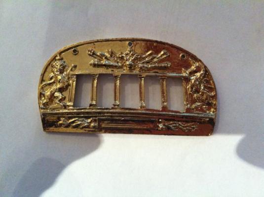
Hi Harlequin: I can't believe you're laying on the planks already! Didn't you just finish the Greyhound? I thought I had a reputation for speed, but you've got me here - nice work - the yellow ochre works well to mellow out those brass parts - how to deal with that shiny brass is certainly a pressing question on my mind, though the Bellona is far away for me....I find myself wondering how the precise paint job you see on the box can be replicated, considering that there is absolutely no "tooth" to that brass to pick up the paint.....how did you get yours with such a nice matte finish? Did you treat the brass before hand in some way? hamilton
-
Lots of folks call me "Hammy", so Ham suits me fine! Enjoying your build greatly, Ham or no.... hamilton
-
Looks great Harlequin! If mine looks half that good I'll be well pleased. As for launching it against the wall - hahaha!! I have a miniature sledge hammer that I keep on the modelling table as I build, just in case....I've had it raised a couple of times and stopped myself at the last minute.....Anyway, great work - seeing her next to the Victory is really gratifying - must be even more so for you! Think of how it will look with the Bellona moored next to them! hamilton
-
Looking great, Andy! hamilton
-
Thans for the compliment, J.! Much appreciated! hamilton
-
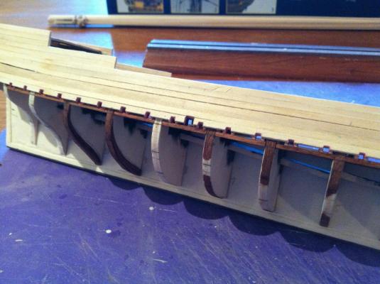
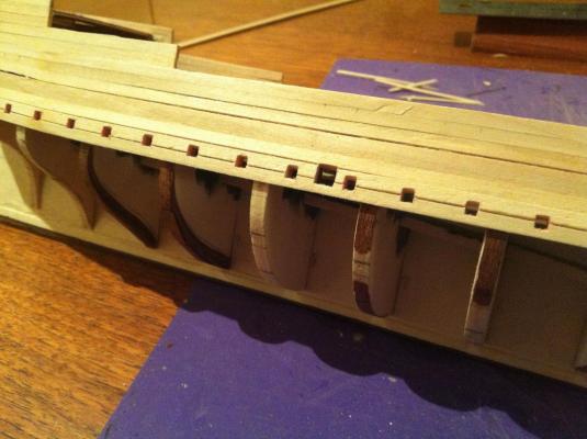
Thanks B.E. - yes I'm pretty pleased with them, though I still have a bit of cleaning up to do.... Initially when I framed them, I also put backings on them (1mm x 5mm basswood). These were added so that I could have something to root the sweeps onto when the time comes. However, I realised when I was planking that having the backings there was going to make filing them out extremely difficult, so I removed them so I could work them properly with a square jeweler's file. I thought to put them back on once the planking was complete in Band "A", but then of course I'd encounter the same problem when it came to the second planking...So now I've decided to use short lengths of 2mm x 2mm scrap wood as mounts for the sweeps that can then be inserted into the sweep ports and glued in. This will actually be the very last thing I do on the build. Hopefully having the sweeps run out will add some interest to the model. Anyway, thanks for stopping by! hamilton
-
I appreciate your critique, Augie, and I'll take it under advisement....maybe it's just semantics, but I much prefer to slather and then wield the sandpaper like a Toreador to tame the filler into submission! Splitting hairs maybe, but...... hamilton
-
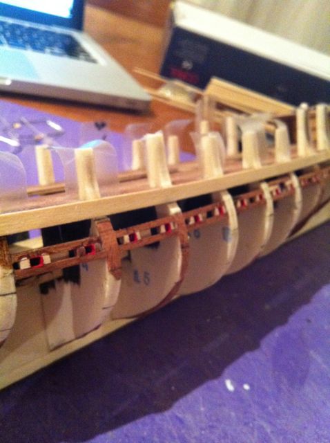
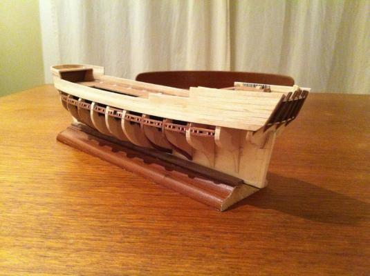
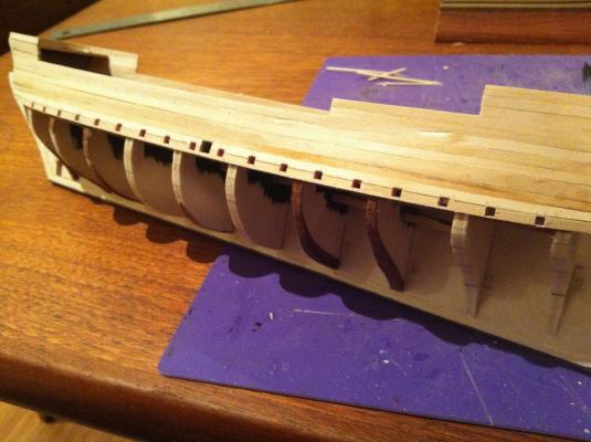
Hello there: I'm now well into the first planking, and though it's looking pretty messy now, I look forward to slathering on some filler when it's complete and sanding it down to a nice smooth eggshell finish! For now, since the last post I've finished the bulwarks and down past the sweep and ballast ports, which I've filed out. The first plank I laid, as I mentioned above, was 5mm x 1mm along the deck line. I then planked upwards with 3mm x 1mm strips - 3 strakes along the waist; 2 3mm and 1 5mm plank for the forecastle (I'll sand this down a bit later); 2 more 3mm strakes to define the first step up to the full bulwark height along the main deck (from bulkhead 11 aft); and then 3 more for the quarterdeck.... When i first finished it up, I thought that the quarterdeck and forecastle were too high...I will reduce the height a bit, as I said, but I've also realised that with the addition of the sheer and cap rail along the waist it actually is quite reasonable - you'll have to wait to see this until the build progresses much further, but for now I ask your trust! Anyway, here are some photos - enjoy! hamilton
-
Thanks Runner! Much appreciated! hamilton
-
Thanks for the confidence booster, Andy. It may be in the works....have to strategise a bit first around just building the facia and then consider decorations...I might try to look around for some ready-made things I could finish appropriately and use....anyway thanks for stopping by Andy - I've been a fly on the wall (no pun intended) on your Fly build - it's a real inspiration! hamilton
-
Harlequin - I feel the same way, though for different reasons - I have no idea what I'm doing! hamilton
-
Hi B.E.: Good eye! I never would have caught that myself....I would definitely prefer to scratch-build the transom, but I really don't know how....Augie has brought up the carving skills - in my case, non-existent at any scale. Goodwin's book contains illustrations of several options and I may try for a simplified version of the simplest one.... Thanks for visiting! hamilton
-
Hi Harlequin: Yes you can really notice the difference, right? I spent a day when I first got the Bellona kit going through the parts list and finding everything on the plans - also noting which plan sheet(s) the various parts could be found on...It certainly looks like a great kit! hamilton
-
Hello there Alistair!! Good to hear from you again. I hope all is well down in NZ and you're settling in for the winter - it's a balmy 24 degrees up here with not a cloud in the sky - a very rare thing for the pacific northwest as you know... I guess I'm quick but I'm trying to take more breaks and take more time to think about things - the modifications necessary on this kit make a quick pace next to impossible....anyway, I'm still waiting for your Pegasus! I know you probably have "other things" to do - don't we all! - but seriously....your skills are far too elevated to keep from the world and horde all to yourself!! On with it now.... hamilton
-
Hi Augie: Thanks! This was a trick I learned from following Bob Hunt's Armed Virginia Sloop practicum - one of those little things that I never would have thought of doing myself, but that makes perfect sense once someone else tells you to do it. As for the transom - I don't know why you would feel bad! It's Corel's shoddy work.....if I may say, I've encountered some pretty bad problems in the past with kits - the Mamoli Gretel, AL San Francisco and Model Shipways Armed Virginia Sloop were plagued by really inaccurate laser cutting and bad wood strips. I've had to shim the outside edges of the bulkheads of every model ship I've built since the Armed Virginia Sloop, so having to do that with this was not unexpected (though I didn't expect how much I would have to!) The problems with this kit are generally not the quality of the materials (with the exception of the transom), but rather the overall poverty of the instructions and plans - which to my mind are a really critical aspect of any kit. Corel uses very high quality wood and their metal parts are, I think anyway, better than other manufacturers (at least the ones I've tried - there are many I haven't!).... I will still build Corel kits after this - I have their Bellona already and am contemplating a Victory, though space considerations at present make that pretty unrealistic....And I would continue to recommend them - though maybe not this particular one unless you're really ready for some mind-bending remediation. Thanks as always, Augie, for visiting! hamilton
-
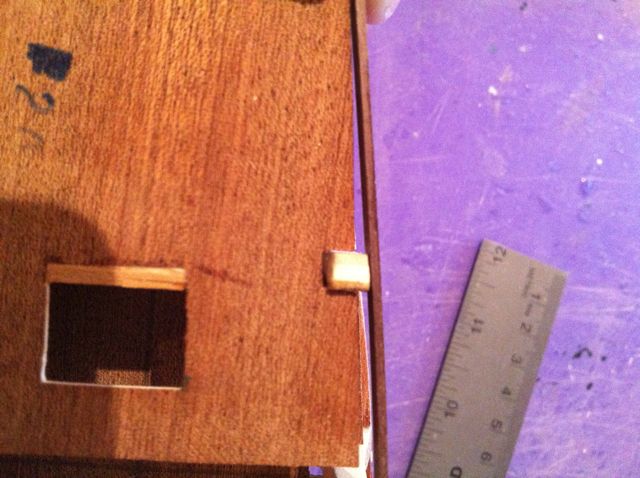
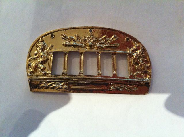
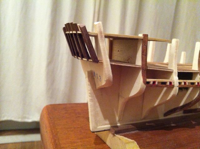
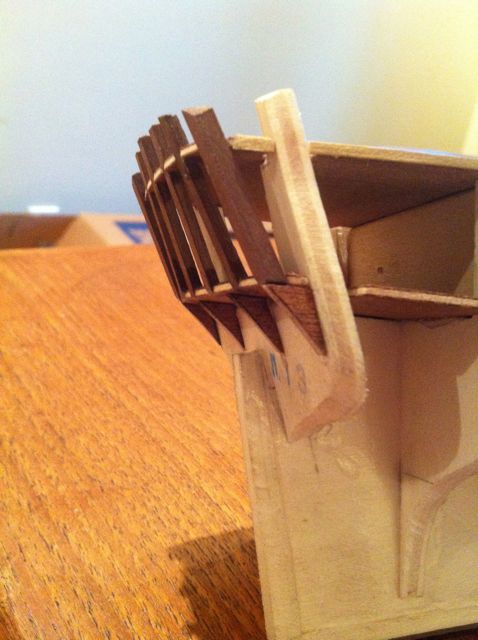
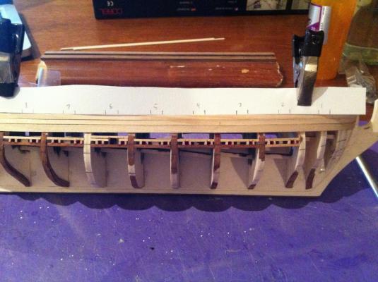
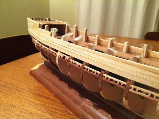
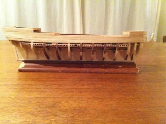
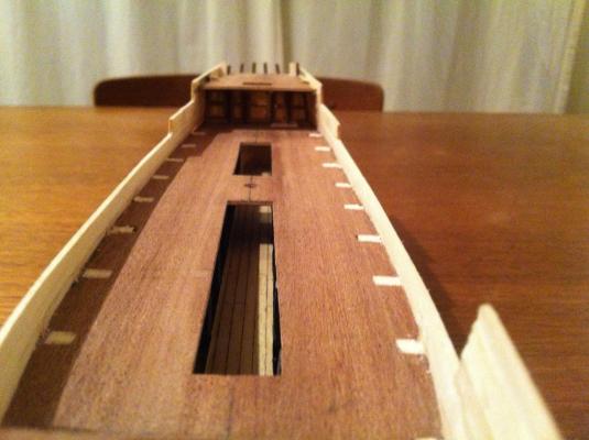
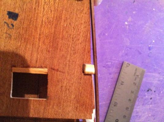
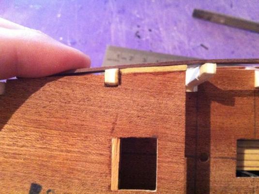
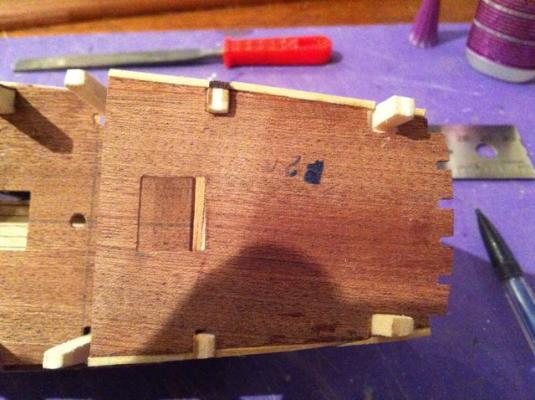
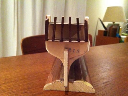
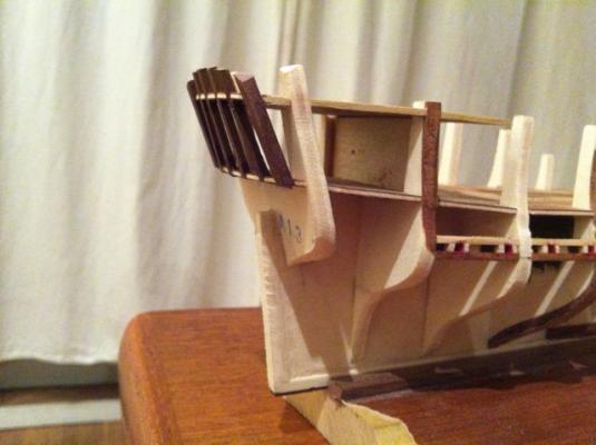
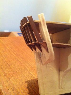
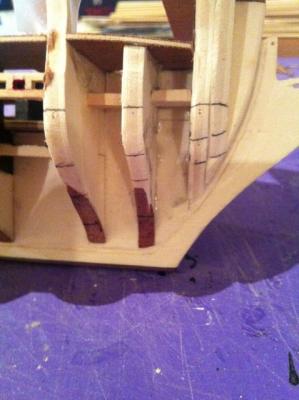
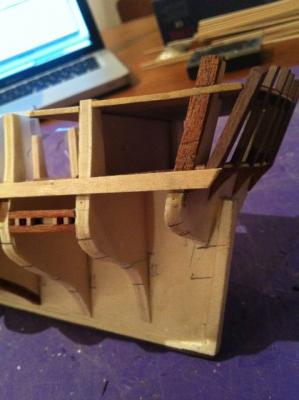
Hello there: I've now finished the framework of the Greyhound, and begun the planking (well....I've laid 2 planks of the first planking....). The completion of the framework involved a few pretty straightforward steps - though as I've come to expect from this kit, these were not without their trials. 1. Fitting the quarterdeck - this photo shows how the edges of the quarterdeck were set back from the run of planks, and the following photos show how I fixed the problem. 2. Fitting the forecastle - a very straightforward operation - no specific photos here 3. Stern framing - the plans called for 3mm x 3mm strips on the outside of the stern and 4 more strips of 2mm x 2mm to complete the stern framing. I didn't deviate from this, but had to alter the slots in the main and quartedeck to square things and make the strips fit. I used the metal transom as a guide so I could be assured that everything would fit - I hadn't taken the part out of the bag before, and I was upset (though not surprised) to see that it is totally asymmetrical - it looks like it melted on one side.....yuck!! Now I'm wondering about building a scratch transom....but my carving skills are non-existent....I might give it a go and see what happens....check out the photo - probably passable (with some weathering) but not really up to snuff.... 4. the counter supports - these came as laser cut pieces, but given the modifications I had to make earlier in the deck to make it fit, I had to reshape these, as well. I was pleasantly surprised to find that even once I had cut them down considerably they still form an admirable space for the counter planking with ample room too along bulkhead 13 for the stern planking. Drilling the rudder hole might be a completely different matter however - only the planking will tell. 5. Planking - I'm starting with the bulwarks, so have not yet done a full hull analysis. I did take a bit of time to mark out bands on the bulkhead edges. I decided on 5 bands, each of which is 15mm at the dead flat - 3 planks of 5mm. 6. Initial planking preparations - The planking arrangement in the plans totals 4.5mm thick (1.5mm first planking, 1mm vertical planking around the metal gunports, 1mm inboard planking, 1mm second planking outboard). This seemed crazy to me, since the caprail is only 4mm wide. Good thing I checked ahead! So I've decided on a few modifications -- I'm not using the metal gunports, since I'm making open bulwarks - this rendered the 1mm vertical planking superfluous. -- I'm reducing the thickness of the first planking to 1mm These changes will bring the full bulwark thickness to 3mm, which will make much more sense. Since I'm following the Goodwin book, I needed to establish the height of the bulwarks, the size of the gunports (7mm x 7mm, and the height above deck of the gunport sills. This has been a bit of a tricky business. But here's how I did it: -- I built one of the canons and a small section of false deck planking to set it on. -- I positioned the canon on deck and measured from roughly the centre of the muzzle to the top of the sub deck - this worked out to about 7mm -- I took a measurement from the Goodwin book (which is admittedly at a slightly larger scale - 1:96 - than the model - 1:100) of the bulwarks (there is no final strake, but rather the caprail rests on the frame ends and defines the top of the gunports. The total measurement was 12mm -- I figured that I would use 3mm planks for the bulwarks plus strips of 1mm wood for the interior gunport frames. This would raise the gunport opening 4mm from the subdeck and allow me to fill in the 12mm space with 4 rows of planks I probably need to double check this, which I'll do tonight, even though I've already laid the first bulwark strake. 6. laying the first plank - The plans call for the first plank (3mm x 1mm) to be laid with its bottom edge flush with the main subdeck. I didn't like this idea, so I started by laying the first plank (1mm x 5mm) with its top edge flush with the top of the sub deck. This gave me the baseline for the bulwarks, and will also define the area below that I need to line off. All that writing, then - and only 2 little photos....here they are.... I'm going to try to move slowly with the planking - I'm a little worried about how I'm going to do the area around the sweep ports...and I'm really going to need to double-check the bulwarks....in any case, what else to do but trundle on? Bye for now hamilton

-
Hi Harlequin: I'm already starting to drool a little. I guess I'm just happy to have something to look forward to over the summer other than yard work! As for finishing - it's such a subjective decision....fortunately it's not one that you have to make immediately.....not, at least, until you start making the cabin bulkheads....not sure how far into the build that will be, but probably some time, right? Maybe at the first opportunity for finishing a part of the model you're going to instal, try it both ways (if that's possible) and see which you like better. Anyway, have fun! I'll be watching with interest. hamilton
-
Hi Harlequin: I'm just about to head over to your Bellona log! Very exciting! Yes - I figured it would probably not be too visible, but thought I'd cover my bases while I still could, just in case. I've now started planking, though I've deviated from the Corel instructions by changing the thickness of the first planking to 1mm and laying the first plank so its top rather than its bottom is flush against the surface of the false deck. I'm also using 3mm planks all the way up the bulwarks. I'll make a more extensive post later to explain the process....I'm still not entirely sure how misguided it is.... hamilton
-
Hi Kutlu: Thanks for the kind words! I certainly hope my changes are "improvements" - right now I'm trying to wrap my mind around the bulwarks and gunports. Math is not my strong suit, which may be an argument against me pursuing this hobby at all! Anyway, I've popped in on your Berlin log - it looks great! I had thought of building it, but when I saw it was single planked I started to balk. Then I saw that there were only 4 sheets of plans and I started to wonder whether that kit has the same problems as the Greyhound...anyway, your build is coming along very nicely. hamilton
-
Hi Augie: I think I will leave the cabin natural wood - it will be shadowed by the quarterdeck anyway, so it won't be too "high contrast" except on close viewing. But who knows....maybe I'll change my mind once I start painting the inboard bulwarks and slosh some paint on the cabin..... hamilton
-
Thanks Augie! My mother-in-law's been in town for the last week so not much progress good or bad lately. Back to the bench tonight hamilton
-
Congratulations Harlequin!! You made it (literally and figuratively). I'm sure you've already had your celebratory libation, but please have another for me! I'll celebrate for you once we reach a more civilised hour in my part of the world. Looking forward to seeing the pictures - and of course to some more progress on the Bellona!! hamilton