shipmodel
-
Posts
941 -
Joined
-
Last visited
Content Type
Profiles
Forums
Gallery
Events
Everything posted by shipmodel
-
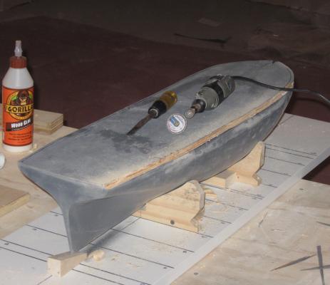
 Hi Ron - The plug is looking good. But cutting a notch for the keel-stem-sternpost in the curved block is going to be really, really hard to get straight. Don't ask how I know this . . . :-)) Let me suggest that while you still have a flat and straight face to the block opposite the keel that you use a table saw and slice the block in half along the centerline. Make the saw kerf the width of your keel. Sandwich a keel-width thickness sheet of wood as a spacer between the plug halves and you will have a straight slot ready for the keel pieces. Dan
 -
Hi Michael - Your cove and hollow system is similar to how I used to make tambour doors for rolltop desks and kitchen counter appliance garages. I used to have a set of router bits that were bought as a matching pair and did quick work of the task. I believe that the worked down to 1/8", but it was a long time ago. I believe that I got them from Constantines' in NYC, which is now out of business, but maybe Rockler has something similar. Just another thought from another Dan.
-
Michael - Yet another excellent and impressive project. Count me in as an appreciative observer. Where do you find the time and energy for all these projects at the same time? Do you sleep at all? Dan
-
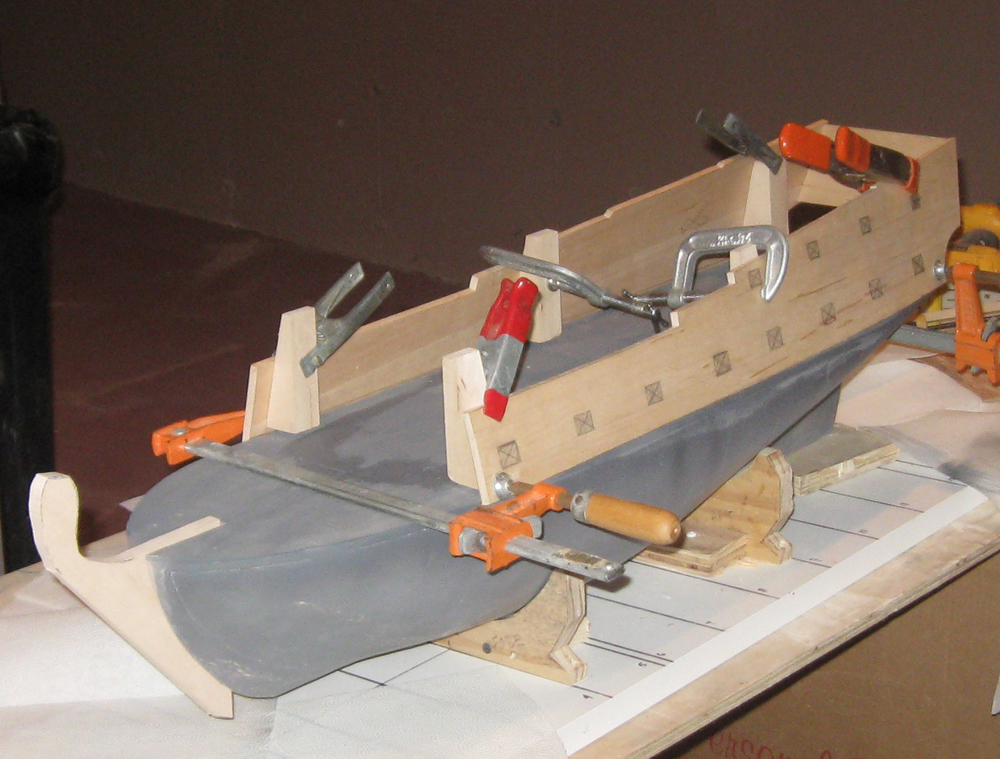
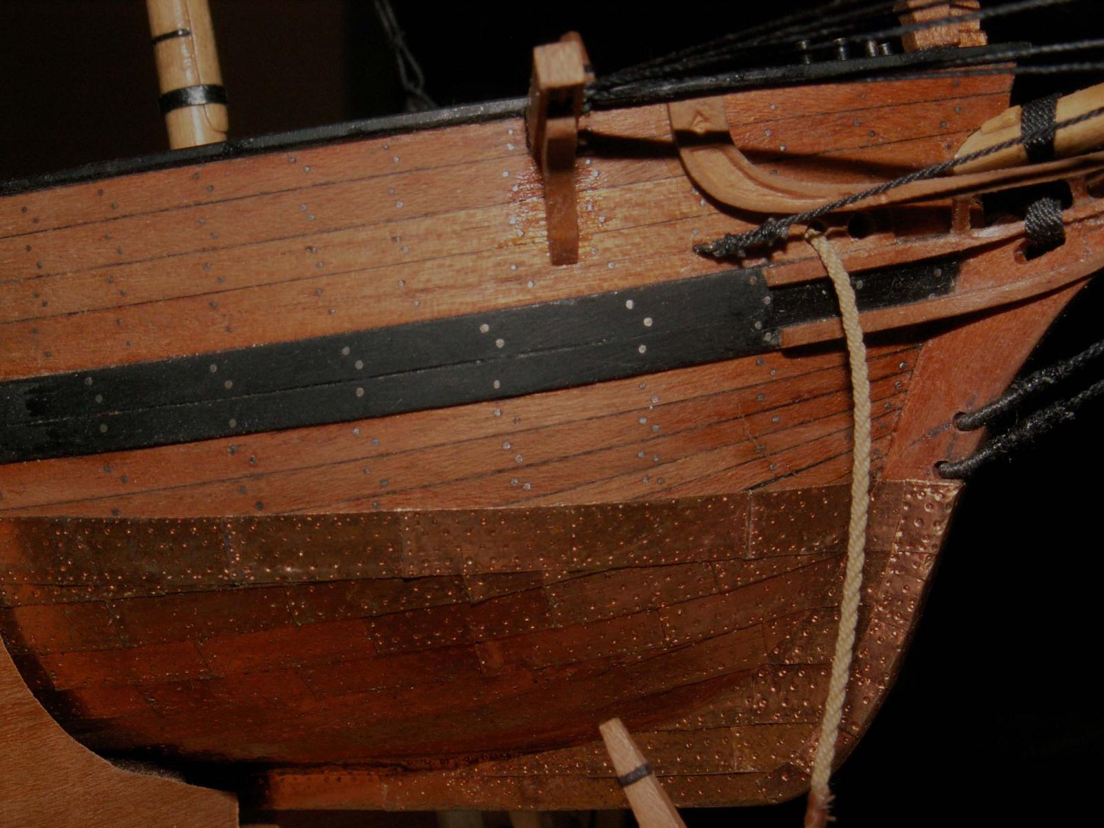
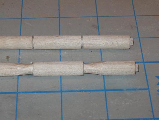
Hello again. I trust that everyone has recovered from Thanksgiving, Hanukkah, and all that tryptophan in the turkey. Not to mention all the family that may have descended on you as they did to us. I have a greater appreciation than ever for the wit and wisdom of Winston Churchill. . . I did manage to get in some work on the hull. The lower portion of the first hull was fully shaped using templates as usual. The aft portion of the gun deck was built up with tapered stacks of basswood to match the rise of the sheer line, then sanded down to make a smooth curved surface at the centerline. A camber (round-up) of the deck of 1/8" from the centerline to the bulwark edge was plotted from the plans. I marked and sanded this into the gun deck surface. When I was happy with the underwater shape and the deck curves, the hull was given its first coat of sandable primer. Rough areas, uneven curves, and other problem spots were dealt with and re-primed. Although the hull will probably be tweaked some more, I started working out the bulwarks and hull sides above the gun deck. Here you can see that the main bulwarks have been cut from 1/4" basswood to the shape taken from the NMM draught. From the transom and taffrail to a point just aft of the forecastle the ship's sides were a consistently flat shape. There will be some curves sanded into them later, and they will be bent to match the perimeter of the deck, but for the internal support, the basswood pieces are more than adequate. At this point they are still flat and straight. They sit with a tumblehome of 13 degrees using the blocks and clamps to get and idea of what they will look like and how they will fit. Here I am cutting the rabbet that the bulwarks will sit in. Since I do not have a router, I cut the horizontal channel using the Dremel grinding disc. I have the large circular saw blade, but the thought of freehanding the cut with the agressive teeth was a little too scary. It took a good deal longer, but if I had slipped I figured that all I would get would be a sanding injury, not an opened vein. Once the horizontal channel was ground, I used a wood chisel to make the vertical cuts that removed wood and established the rabbet. It was cleaned up with sanding blocks, then the inside face was angled to match the tumblehome. Back in Brooklyn I returned to the masts. Here are the two topmast blanks. As shown on the plans, the mast shaft is offset towards the aft edge of the square heel. In the photo you can see that I used the Preac to cut down the forward face of the square blank. At the heel you can see it more clearly. The port and starboard faces of the stick were cut down half the amount that the forward face was, which squared up the stick again. Now I could mark it out, cut the tenon with the table saw, then plane it octagonal as was done with the lower mast. The square stick was shaped to a cylinder. Then the upper and lower edges of the wider section that holds up the trestletrees was cut on the table saw. I whittled the wood down till it matched the cut channels. Then the balance of the wood was removed with sanding drums, sanding sticks and sandpaper. At the heel you can see the construction sequence clearly. The three sides are reduced with the table saw, then shaped with the sanding drum to fair the offset round shaft to the square heel. Once the heel is shaped, a fid hole is drilled through and squared up with a needle file. Two mock sheaves are drilled and shaped on an angle that ultimately lines up with eyebolts on the cap. These are for the leads of the lifting ropes. The completely shaped topmasts were give a coat of finish and set aside. The mast caps were shaped from the plans from pear. They have the Continental humped form, with holes and grooves along the edges of the cap for the lifting ropes. They were made from a forward and aft piece, with a notched seam held together with iron straps. Straps also crossed the bottom, fore and aft faces of the cap. Here is the blank with the hole for the topmast drilled. The other has been shaped and the seam between the forward and aft pieces scribed as before. The piece was finished and the straps glued on. The straps were drilled for 0.020" iron wire pins. These were inserted and cut off long before being glued. Once the glue dried they were cut almost flat, then peened smooth. Four eyebolts were drilled and mounted on the underside of the cap through the supporting straps and the caps were complete. The topmast trestletrees were cut and shaped to match the plans. The crosstrees were shaped from wider pieces of wood so they could splay out, then half-lapped into the trestletrees. Holes for the shroud lines were drilled before they were tapered per the plans, then finished. The topmast cap was cut and shaped much like the lower caps, but these were one piece units with iron straps that could be opened when the topgallant mast was taken down. This is useful, because the truck at the masthead won't fit through the opening without opening the strap. So here are all the components of both main masts. The second topmast, the upper one in the photo, had a knot in it that took up the stain badly. I will minimize it with a darker finish, but in the fullness of time it will be replaced and used as one of the spare spars that will fit along the open waist in the finished ship. Here they are all set up. From the deck the mast reaches some 31 inches to the truck. This is going to be one mother of a fully rigged model. There will probably be a longer break until my next post. I will be building the foremasts, which are almost identical to the main masts, so no new techniques will be used. I will be back when they are done. Happy Holidays to all. Dan


- 241 replies
-
- 14
-

-
- queen annes revenge
- pirate
- (and 2 more)
-
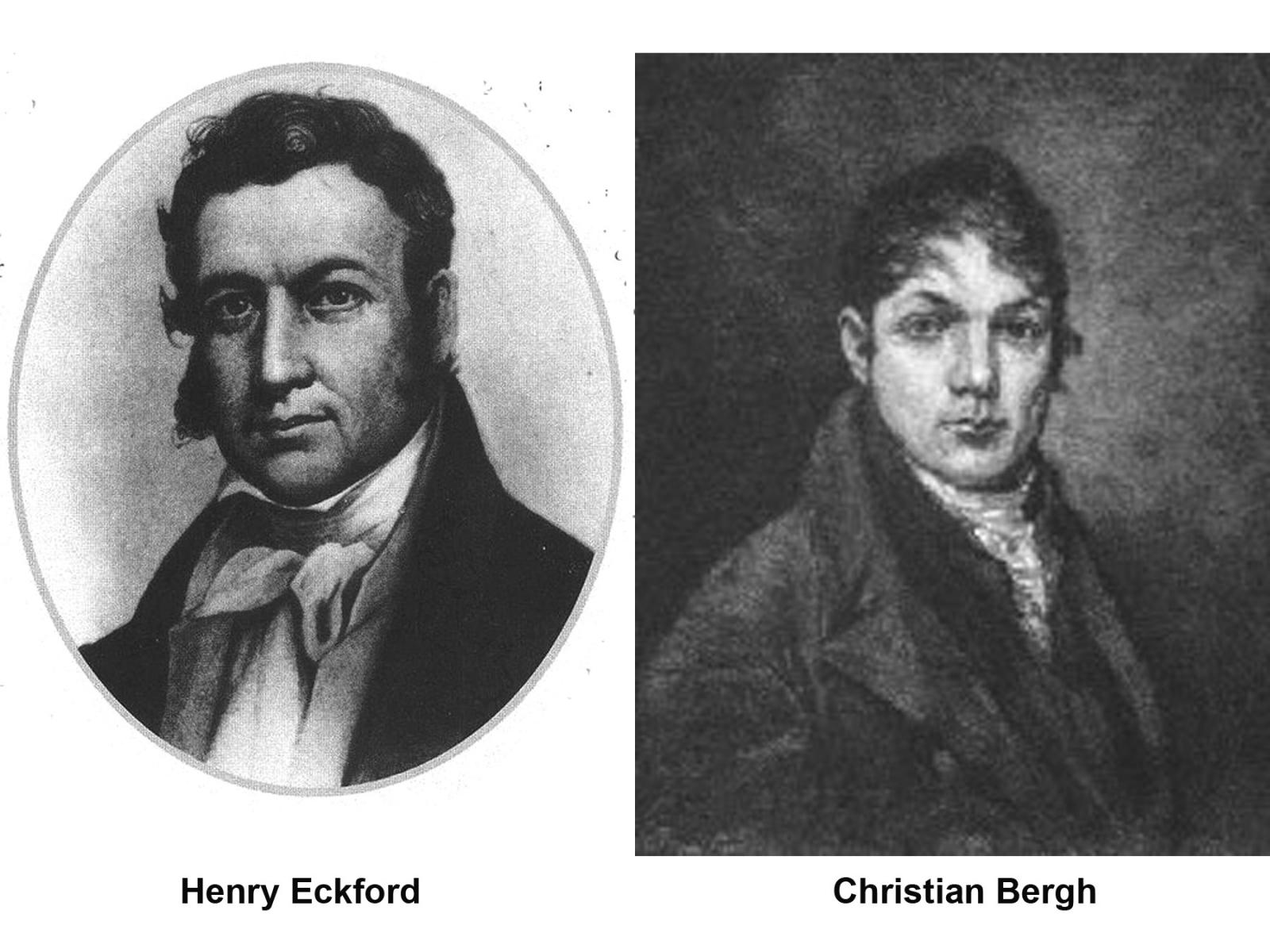
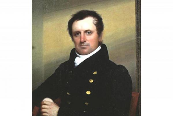
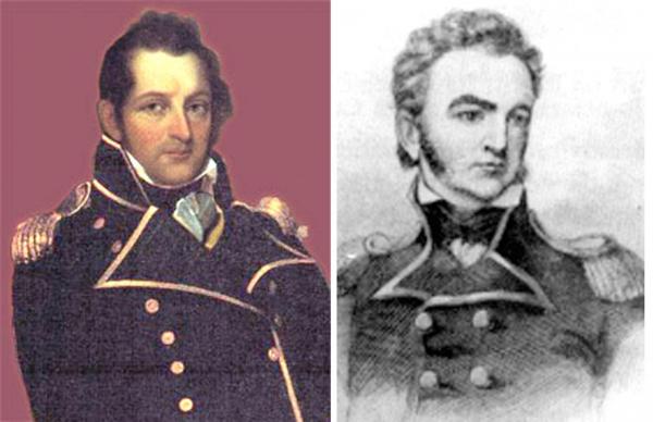
Ron - Really nice work. There is a growing impression of standing on deck of a real ship. Is that Woolsey supervising the work, or Christian Bergh, or even James Fennimore Cooper? Woolsey Bergh Cooper Thanks for sharing your excellent work. Dan

-
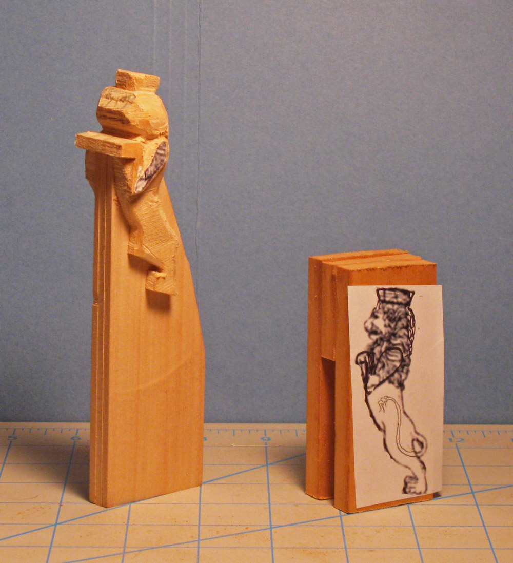
Hi Daniel - What a treat to see a real miniature of the model I am working on. You are really capturing the essence of the ship in a really tiny way. As for scale, my model will be 36.5 inches when measured on perpendiculars from the top of the taffrail to the front of the stem, which is what I see for your model. Multiplied by my scale this gives a length for the actual ship of 1314 inches, or 109.5 feet. If your model is one inch long, give or take a bit, I don't think you would be far wrong to say that it is 1:1250, which is a common miniature scale. I've bookmarked your build and look forward to future installments. Happy Thanksgiving to you and yours. Dan
-
Excellent joinery, as always, Michael. Impressive work with the eyebolts too, as everyone has said. What finish are you thinking about for the cabin? Dan
-
Hi Ron - OK, I set up an album in the completed scratch-built forum under the title "Oneida (1809) US brig of war". I hope the photos are useful. Let me know if you have any questions. Continued success with your work. Dan
-
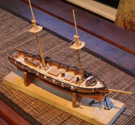
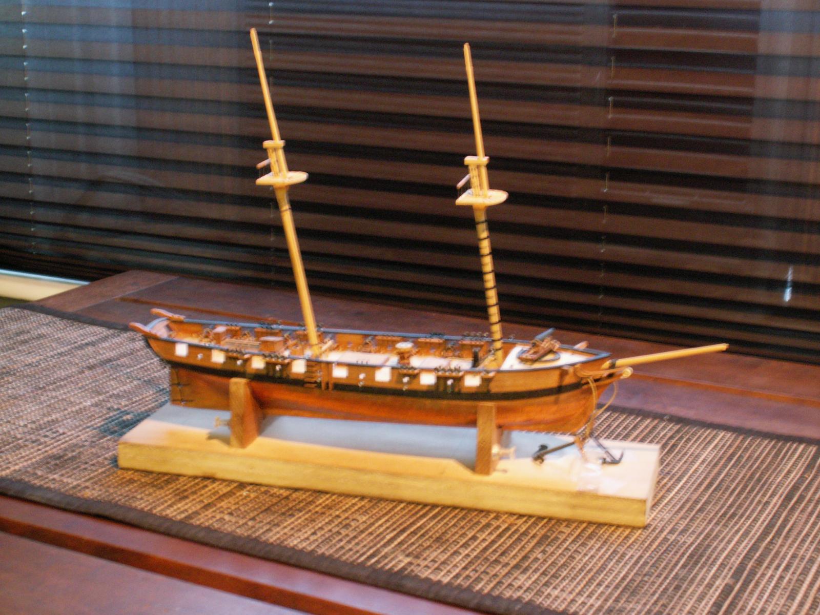
Hi Ron - Just found and finished reading your log. You are making great progress and I really like the way you constructed the capstan. I got interested in Oneida some years ago, and ultimately did a lot of historic research on the First Battle of Sackett's Harbor, which was the first naval battle, and may have been the first of any battles in the War of 1812. Quite a significant little scrap, which kept the British/Canadians from taking control of the Great Lakes. Oneida's gallant captain, Commander Melancthon Woolsey, is a true unsung hero. I also built a 1/96 scale model of her per Chapelle's plans. It has the raised deck and pivot gun, later removed by Woolsey. After I found that piece of information construction was halted, and other projects have prevented completion of the masting and rigging. Here are a few photos for comparison, if they are of any help to you. Be well Dan


-
Michael - Teriffic woodworking on the cabin. The huge 'sanding stick' is an elegant solution to the problem. The joinery is superb. You should consider submitting some photos to Fine Woodworking for their Reader's Gallery.when you are done. Thanks for sharing, as always. Be well Dan
-
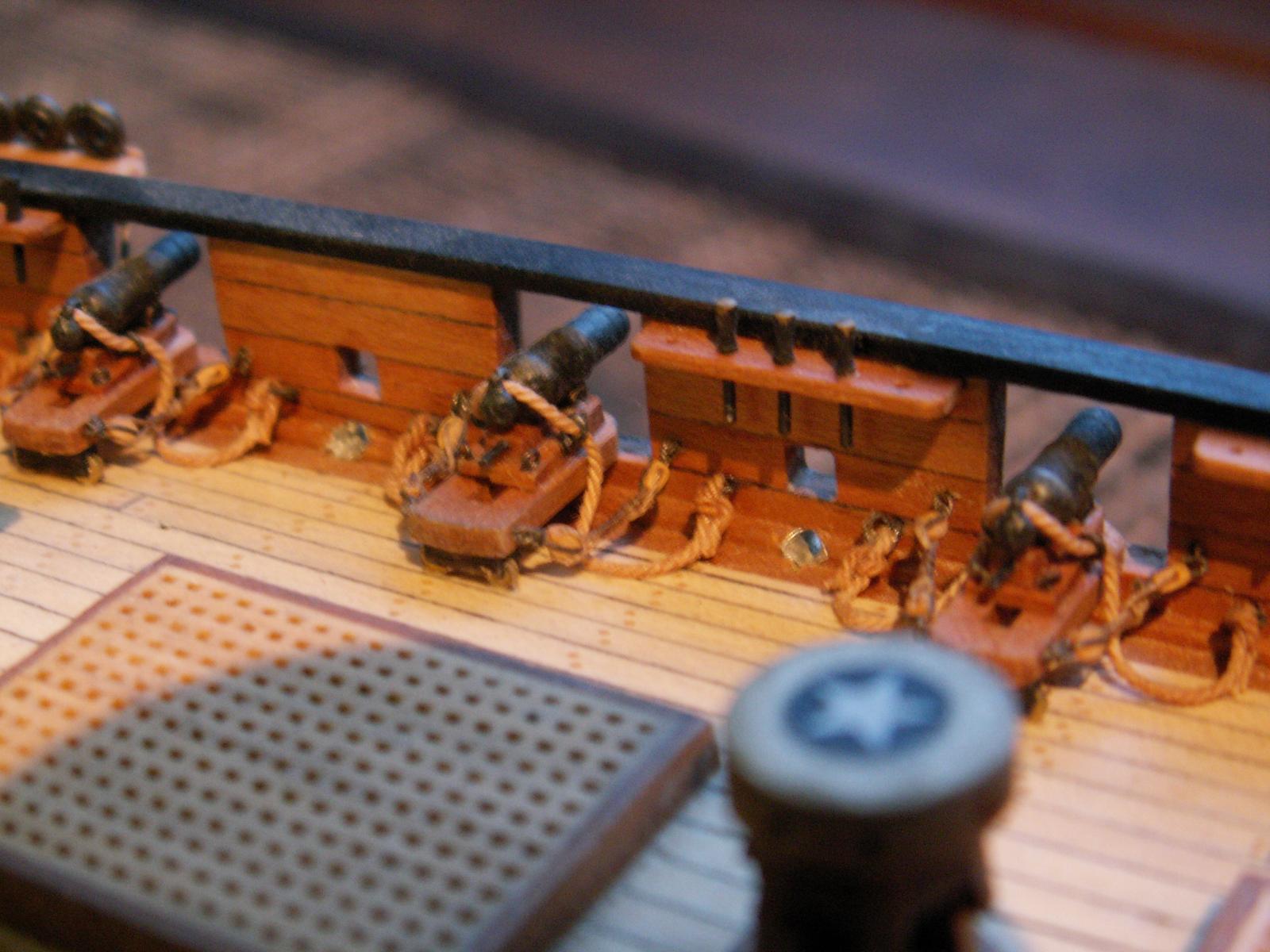
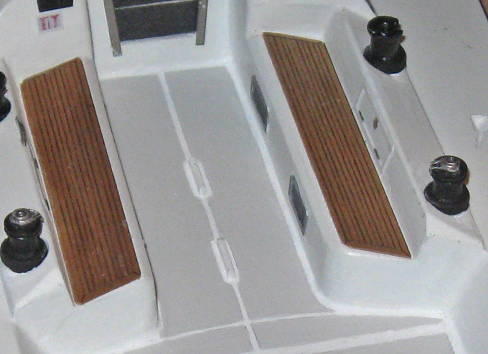
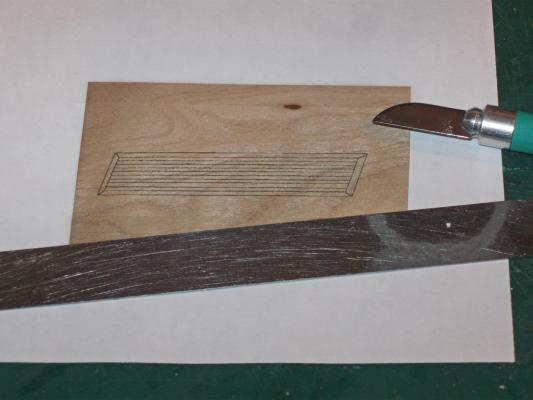
Hi Daniel - It really is just as simple as it sounds. If you look at the plan for the bolster there is a zig-zag line dividing the forward and aft pieces that fit together. Once I had the shape of the bolster cut and tapered, I drew on the line with a straightedge and a sharp pencil. Then I went over the lines with the straightedge guiding the back (dull) side of a #10 blade, the curved one, not the pointed #11 blade. I pushed down fairly hard to make a groove in the wood. This would have made a visible line all by itself, but I find that doing this pushes the graphite from the pencil down into the groove, darkening it and making it stand out. I used this same technique on the teak bench seats for the Swan 42 model. In the computer I drew the multiple wood pieces for the seats, the side-by-side planks and the perimeter framing. Once it was done to my liking and sized to the model, I printed it out onto thin veneer. It looked good, but when I scribed the lines the printer ink was driven into the grooves, making seams that in some indescribable way look much more realistic than the simple printed version. Anyway, it seems to work for me. That's my story and I'm sticking to it. Dan

- 241 replies
-
- 7
-
-
- queen annes revenge
- pirate
- (and 2 more)
-
Hi Crackers - A good question. My best answer for this is that transitions in shipbuilding were gradual things, not easily pinned down to a precise cutoff date.. Since the 1600s circular tops first lost their high sides, then they lost their low rims, and by the end of the 17th century were simple flat platforms. As you said, in English practice they started to lose their circular shape during the 18th century. But this transition would have come later to French shipbuilding practice, especially in a yard that catered to private firms and families, rather than the more cutting edge yards that worked for the French Navy. The change also probably came earlier to larger ships where the savings in weight could have been substantial. To put it another way, Lees, Marquhardt, and zu Mondfeld all show a circular top dated around 1700 for Continental practice. The clincher is that Budriot draws the plans that way, and I am tasked to follow the plans. Who am I to argue. . . Be well Dan
- 241 replies
-
- 1
-
-
- queen annes revenge
- pirate
- (and 2 more)
-
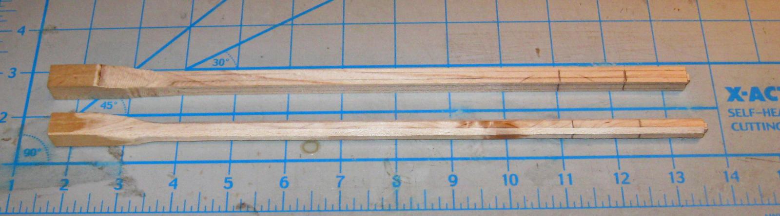
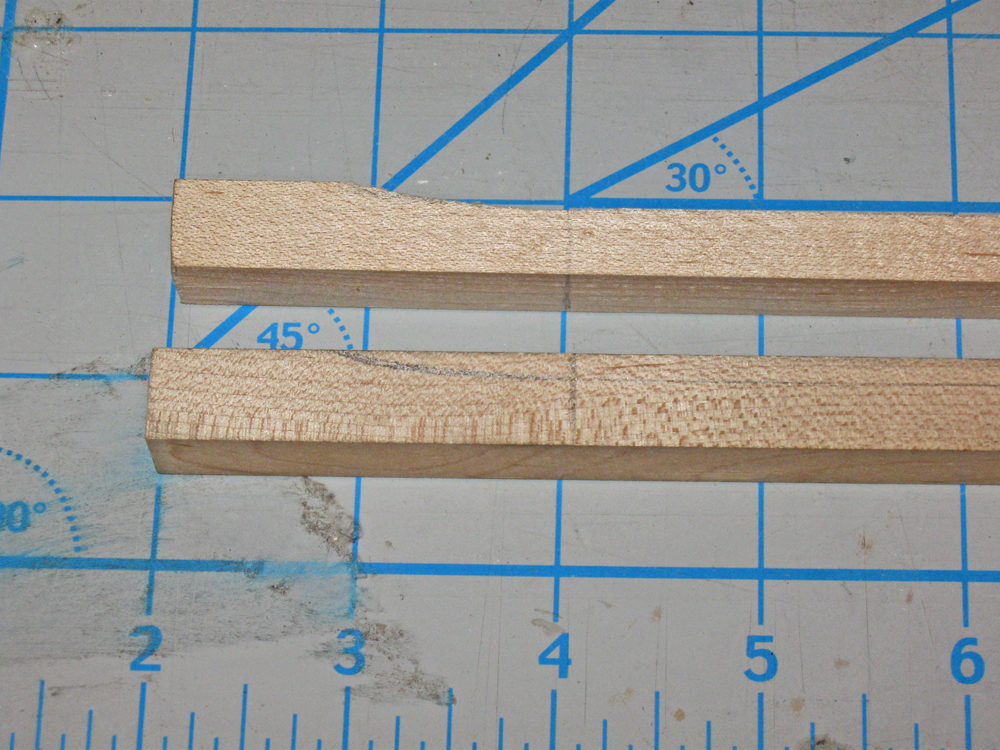
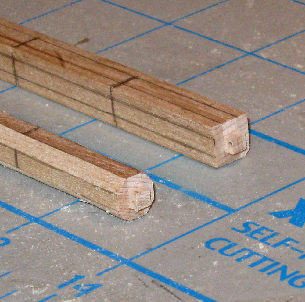
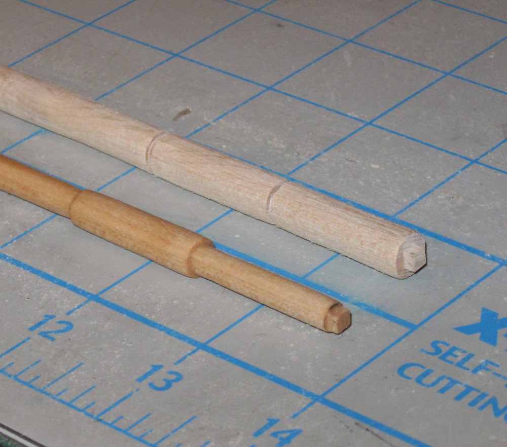
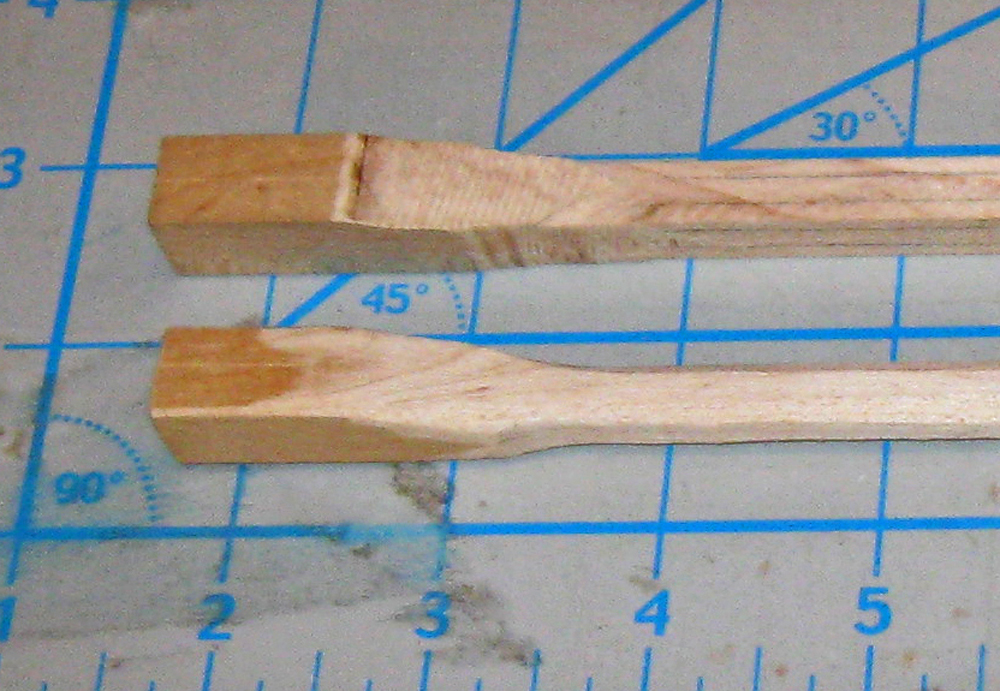
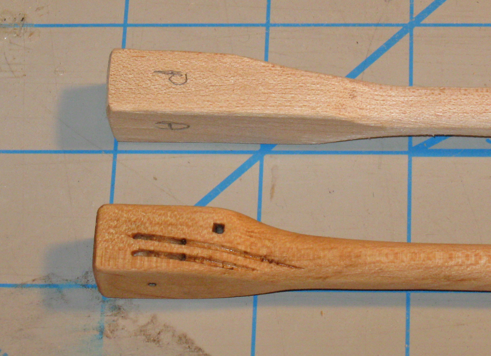
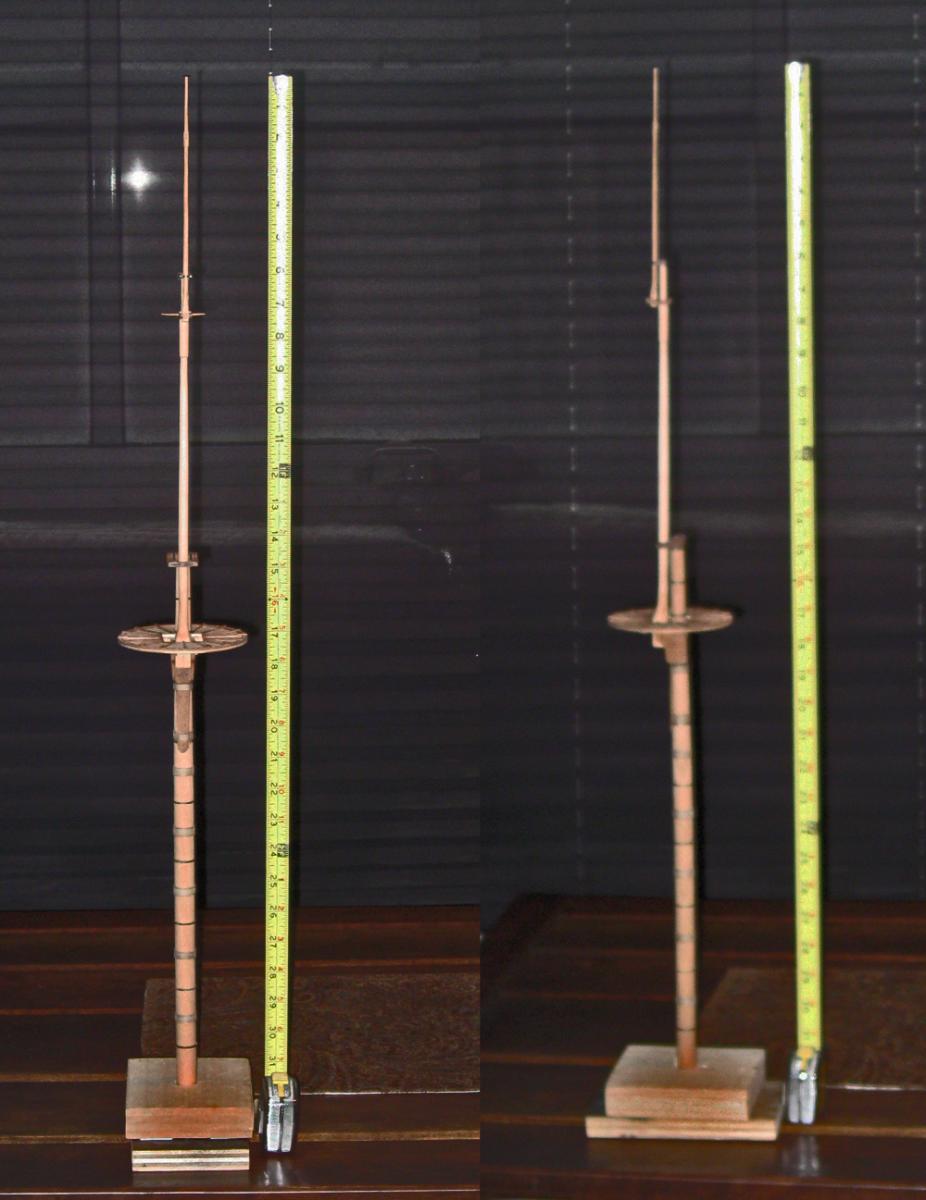
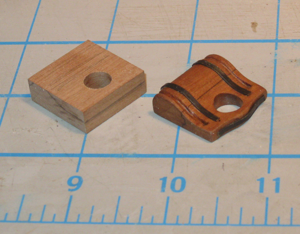
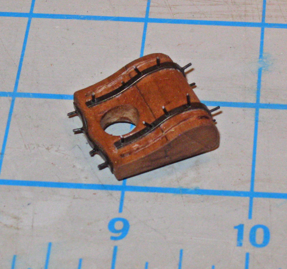
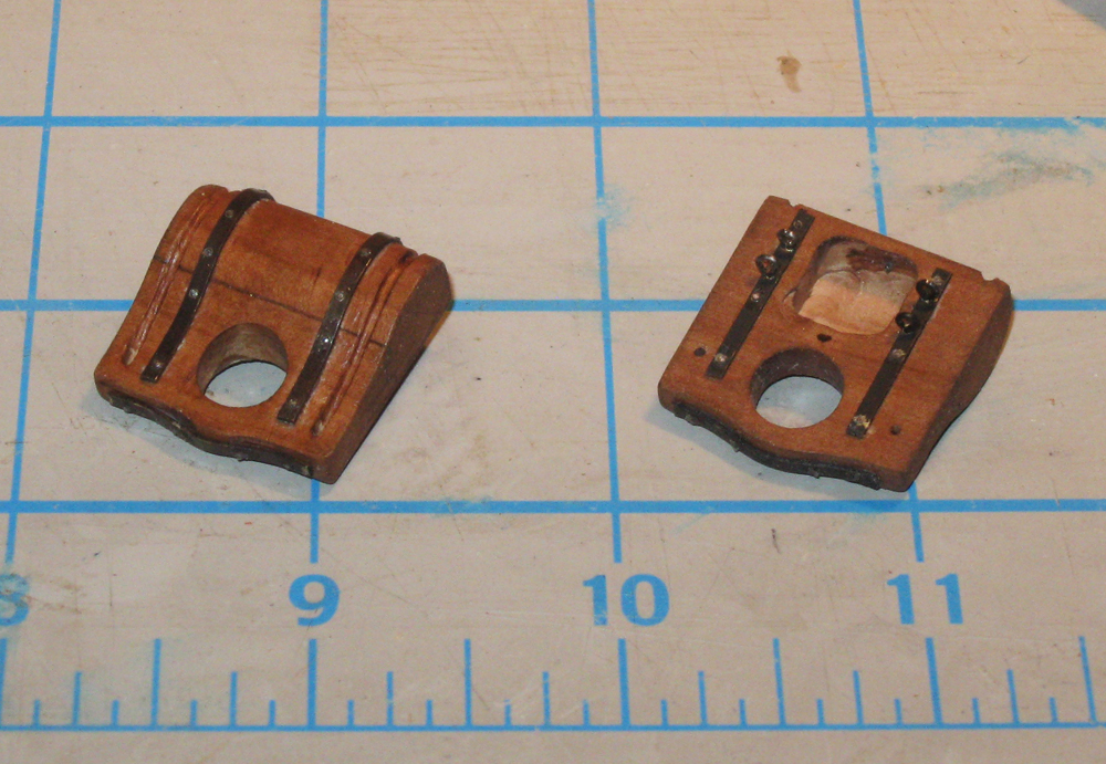
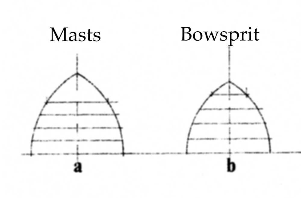
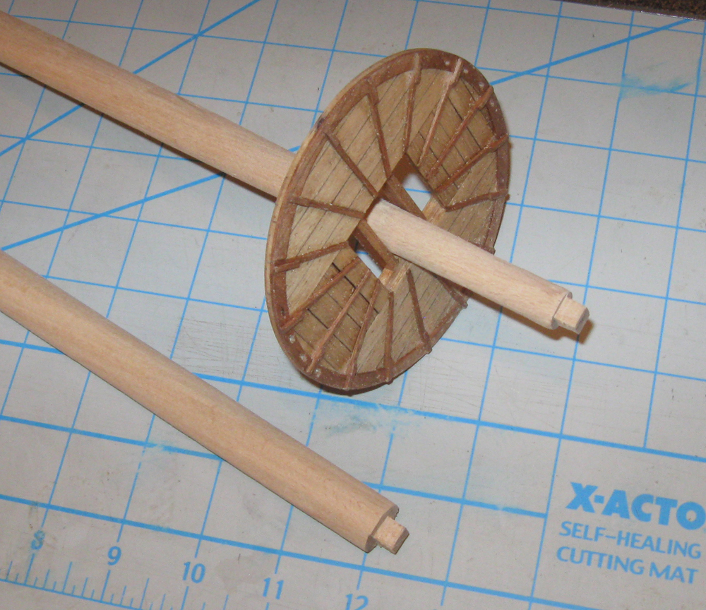
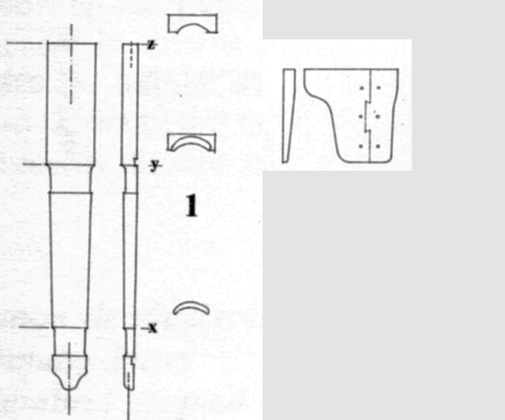
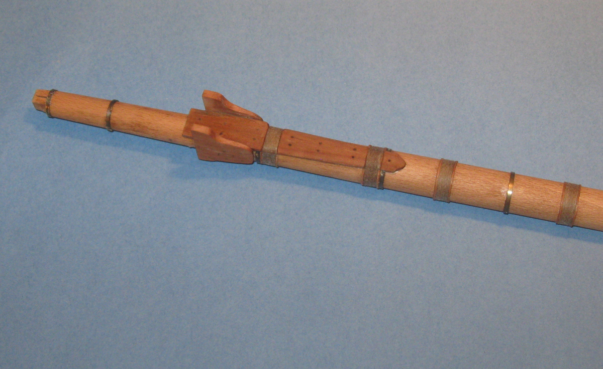
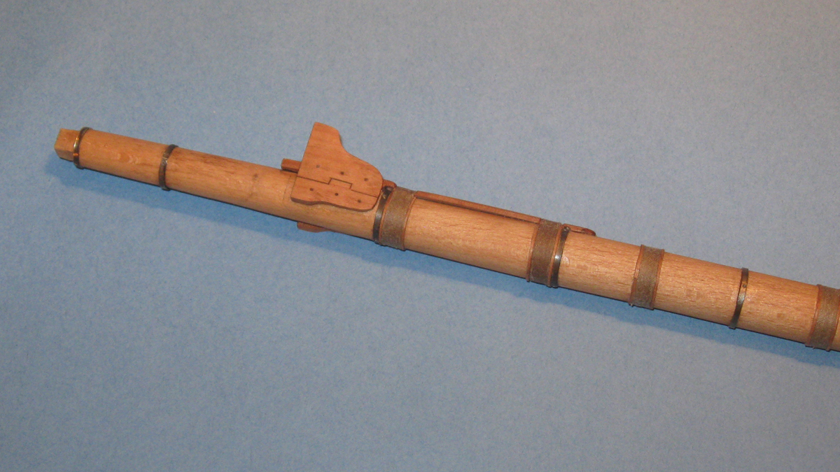
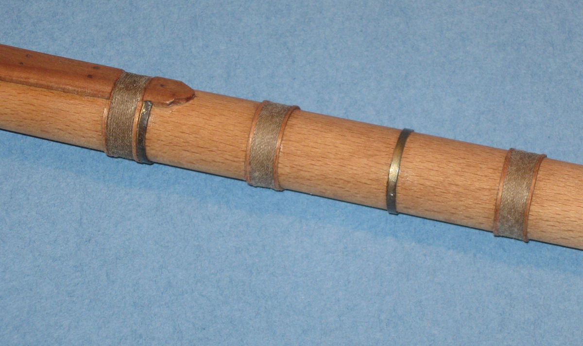
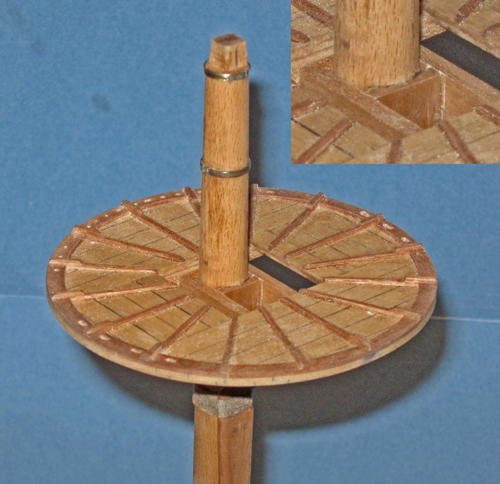
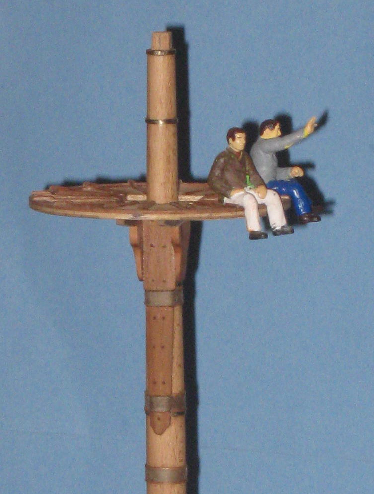
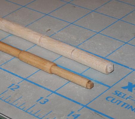
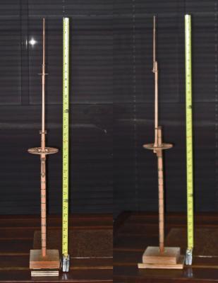
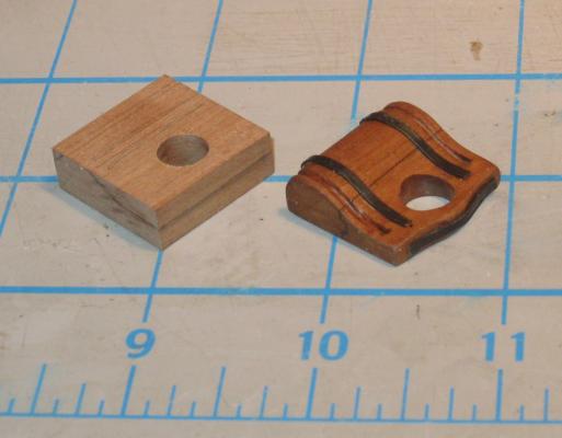
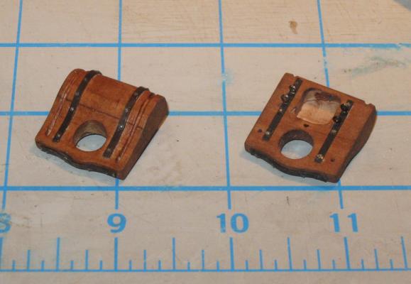
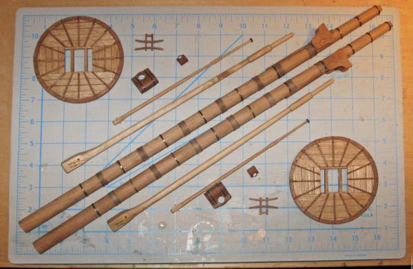
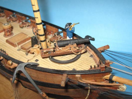
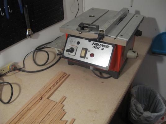
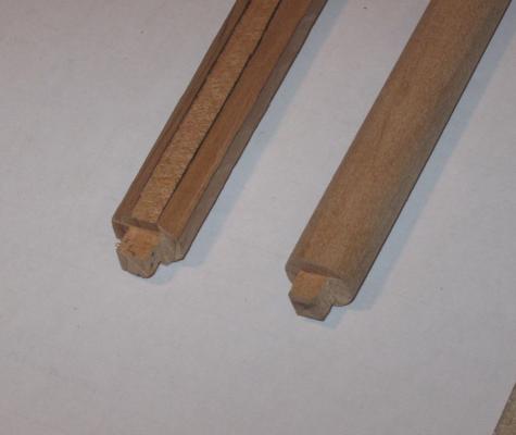
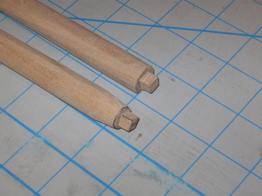
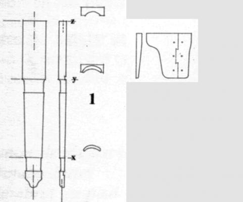
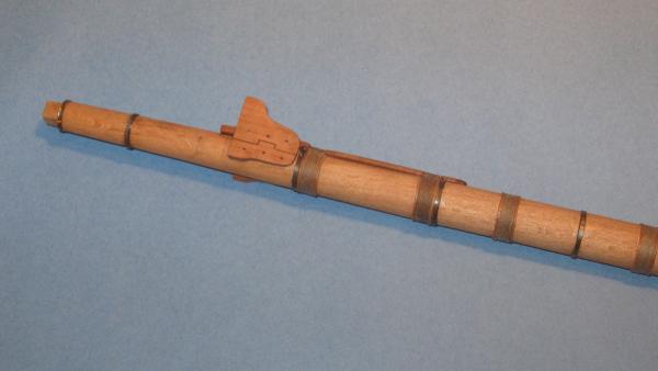
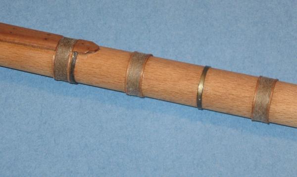
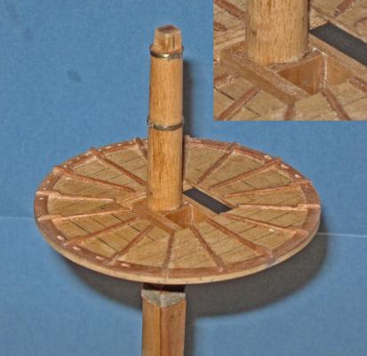
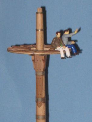
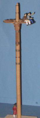
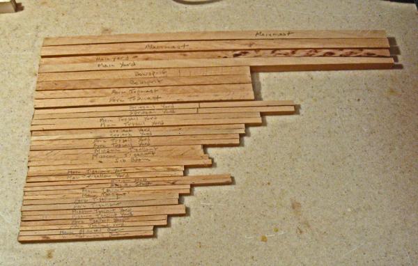
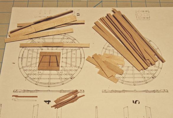
Hi all - thanks for looking in. Another week, another report. The hulls are not going as well as could be hoped, so here is another deour. To go with the tops that were built last time, I am now making the masts. I took a plank of rock maple and cut it down to the dimensions of the masts and spars that I measured from the Budriot plans. They are cut as square sticks sized to the largest width of the ultimate mast or spar, then cut to length. As long as I was cutting, I cut duplicates for the two models. Here are most of them, from the 5/8” x 19” of the main mast, down to the 3/16” x 6” of the main stunsail boom. These were all cut on a Hegner Mk 4 multi-tool. It is a mid-sized tool that fits between the Preac and a full sized table saw, and is perfect for the size of the QAR models. It has a table saw, router, disc sander, and a Jacobs chuck that can power a flexible shaft grinding tool or an add-on lathe unit. I picked it up used and it came without an instruction manual, but I am figuring it out as I go. After all of the pieces were cut, I turned first to the main mast. It is a fairly simple tapered cylinder. I planned to use the lathe on the Hegner, but it will only take 12” work pieces, not the 19” of the mast. Without access to a larger one I went back to basics to carve the mast. The first step was to cut the tenon for the mast cap while the blank was still square. The blade height and rip fence were adjusted on the table saw and the tenon was quickly cut out on all four faces. Then the blank was made octagonal. This was done in the usual way by marking out the 2-3-2 divisions down the length of the blank with a dividers. With a sharp block plane the corners were taken down to the lines, resulting in the eight sided stick on the right. After the corners were marked up as sight guides, they were taken down and rounded with a coarse disc in a hand-held random orbit sander. I didn't find it difficult to do this, since it only had to be accurate enough for a first approximation. I paused frequently to mark up any high spots that I felt when I spun the blank between my fingers. Then they were sanded down and the process was repeated till it felt round. Once the round blank was achieved I went to the plans and determined that the diameter just under the cap was 7/16”. This was marked onto the top of the mast using a circle guide. Using a coarse sanding drum in the Dremel I took the mast down to that size in a sharp taper right at the top. I would pull the drum towards me, grinding off a thin slice from the mast, then rotate the blank a little and repeat. One corner of the top tenon was marked so I would not forget to make a complete circle before checking my progress. From there I moved down the length of the blank: grinding a strip with the dremel and turning the blank a little bit, grinding and turning, grinding and turning. In essence, I became a very slow lathe. After doing this for a while I would smooth out any humps and hollows that developed by sanding the blank on a sheet of sandpaper which has been glued to a piece of plexiglass laid flat of the workbench. This process would have taken much longer if the mast had a straight taper from base to cap. However, the plans had these two little beehive drawings which had to be the tapering diagrams. They were only designated ‘a’ and ‘b’, but after comparing them to the plans I determined that the one on the left fits the three lower masts, while the one on the right fits only the bowsprit. This tapering process continued for what seemed like a very long time until I could slide the mast up through the top with the masthead extending above the top as indicated on the plans. Now the pieces to support the crosstrees and top were made. Unlike English practice, there are no hounds, cheeks or bibs. Instead, the French at the time used only a front fish that fit to the mast and slid up between the crosstrees. A two-part bolster was fitted to each side and treenailed to the mast and to the front fish. Here are the plans. The fish was made out of pear and treenailed to the mast with walnut dowels for contrast. The fish is also held in place by a pair of wooldings that lie in broad grooves carved into the face of the piece. The bolsters are also pear and treenailed with walnut. The only technical point here is that it was made in one piece, not two. The staggered separation line was drawn on in pencil, then the back of a #11 blade was used to scribe the lines, which tattoos the pencil marks into the wood. The mast is reinforced by alternating iron mast bands and wooldings. The bands are made from 1/16” wide brass strips which are wrapped around the mast and sized to fit, then chemically blackened. They are attached temporarily with glue before holes are drilled for metal pins. Each end of the strip where they meet gets one, and a third is placed on the opposite side of the mast. The pins are annealed iron wire which is inserted, glued, and clipped short before being peened smooth. You can see one on the band near the bottom end of the front fish and another just below the light reflection on the other band. Working in a large scale like 1/36 will allow me to build some details much as they are made in full sized practice. The wooldings are a case in point. A cherry strip was cut, soaked and bent around the mast before being glued in place. 3” rope (1” diameter) is wrapped 13 turns around the mast, packed tightly against the wood strip, and cinched tight. A second cherry strip is added to the other side of the wrapping. A painting of dilute PVA glue secures everything. Once the glue is dry, everything was given a coat of the finish and rubbed down. The top was fit back on the masthead to see that everything fit properly. The inset shows how the front fish comes up to the level of the top of the crosstrees and takes the place of the spacer that, in English practice, separates the masthead from the heel of the topmast. There is a third mast band that should be around the masthead just above the top, but the platform would not fit around it so it was removed until the top is permanently attached to the mast. [sharp eyes will also notice that the crowsfoot holes are towards the back of the mast. This will be turned around before the top is attached]. So here are two of the shipyard workers just skylarking on the main top. One seems to see a friend on the ground. It’s a good thing that Dread Pirate Peter hasn’t spotted them. He has some pointed questions to ask about the location of crowsfoot holes. And why the bands and wooldings stop halfway down the mast. Auf wiedersehen . . . Dan


- 241 replies
-
- 14
-
-
- queen annes revenge
- pirate
- (and 2 more)
-
HMS Sussex by mij - Scale 1:48
shipmodel replied to mij's topic in - Build logs for subjects built 1501 - 1750
Mij - What machine did you use to resaw the cherry? A band saw or table saw? Can you show us the jig, please. I will be following your build as avidly in cherry as in tulip. Dan -
Hi Michael - Ingenious jig to slice the brass tubing. I will have to remember it when I need a similar solution. I also like the photos with the odd ropes and fittings lying around the deck, just like a real ship under construction. Very nicely done. Like Jay, I would love to know how you take photos with such depth of field when you are not even holding the camera. Be well Dan
-
Hi Daniel - Thanks for the compliments, but you are giving me way too much credit for the research. It is all the product of the team down at the North Carolina Maritime Museum, and made available online by the North Carolina Department of Cultural Affairs. Here is the link to the History page: http://wayback.archive-it.org/org-67/20120514234115/http://www.qaronline.org/History/historyintro.htm My own research is more aimed at resolving modeling issues, such as the differences between French and British rigging practices of the period. Be well Dan
-
Frankie - Nice look to the water. The waves and whitecaps bring out some of the violence of the scene. I also like the contrast with the color of the Kraken's body - a nice angry octopussy sort of color. Dan
-
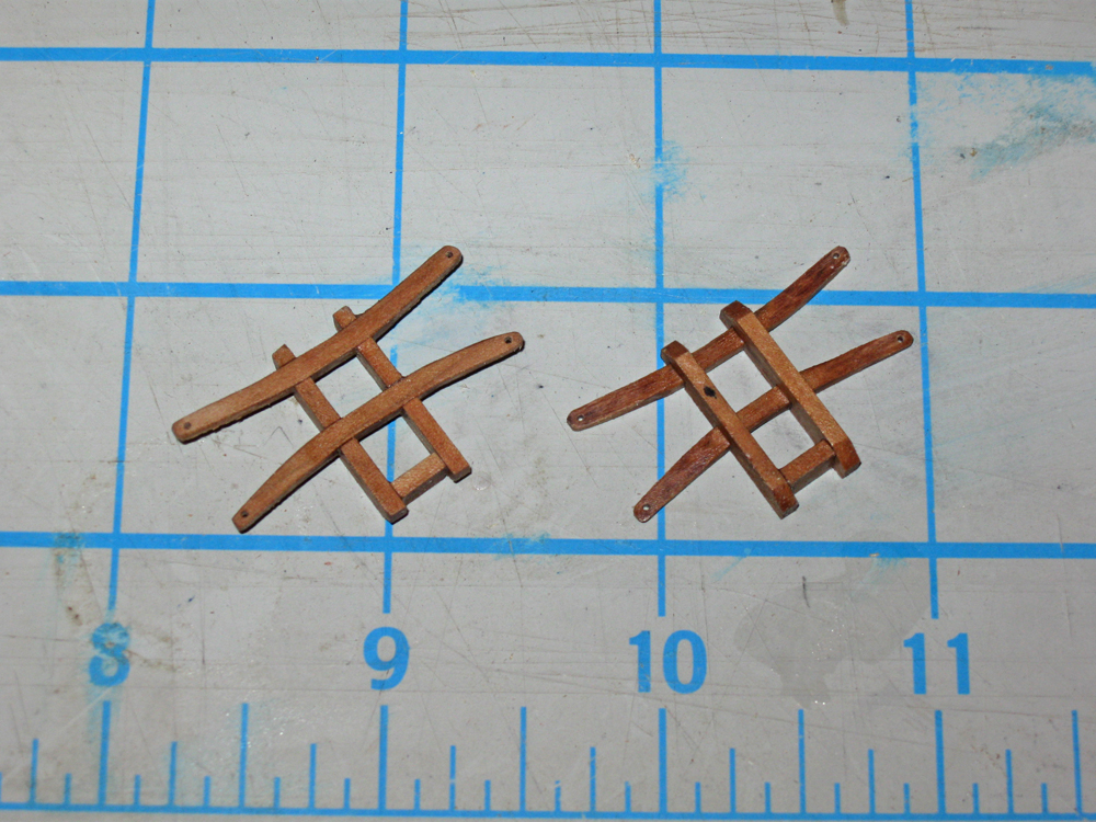
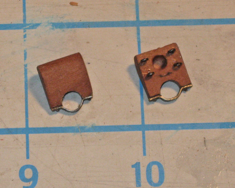
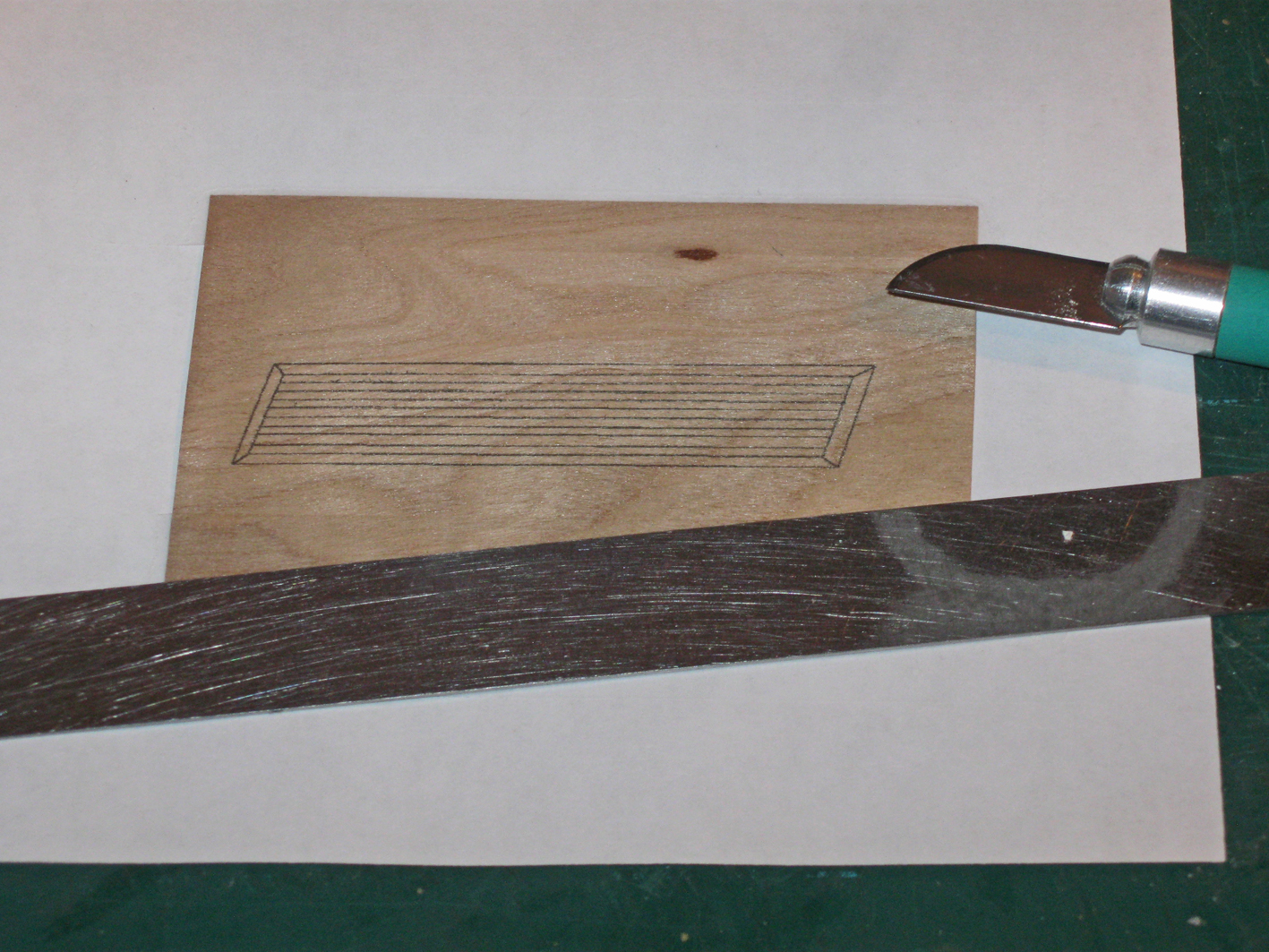
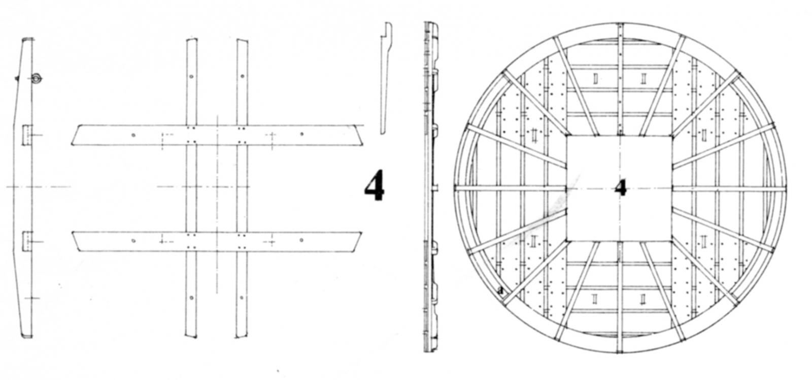
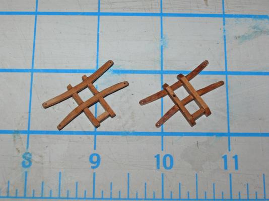
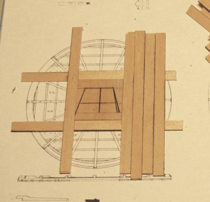
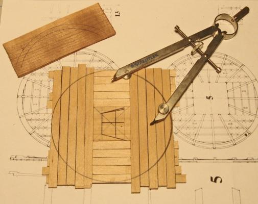
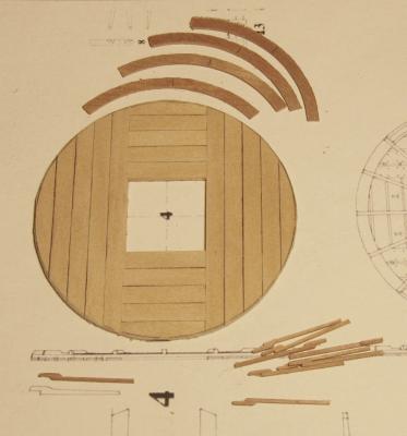
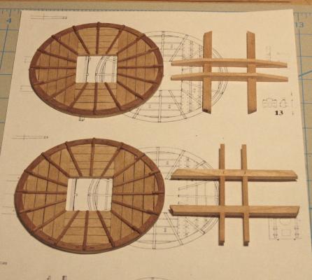
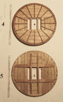
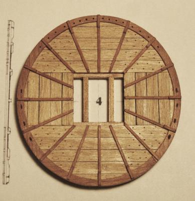
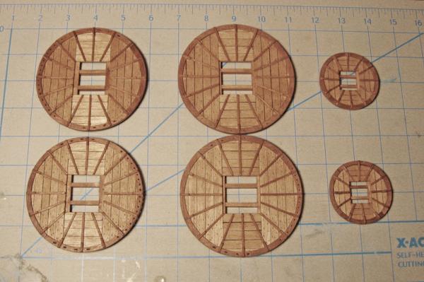
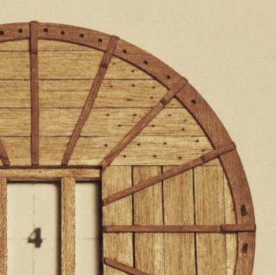
Thanks for all the nice compliments. Michael - I will trade some of my carving skills for your metalworking expertise. I just finished reading your log of the Bristol cutter and was blown away. Ken - yes, the jaw is the major problem, but the width of the eye sockets also seemed too broad. Here is the face after narrowing. The lion is coming along nicely, but has a ways to go. If my artistic skills are up to it, I want to get a ferocious expression, but that may be hoping for too much. After putting the lion to bed for a while, the next independent pieces that I turned to were the mast tops. By 1710 in France they were circular but without the earlier raised rim. They are built with the usual overlapping plank construction, a flat rim and radial cleats. Here are Budriot’s plans, which are almost identical to Lees’ and Marquhardt’s. This is the main top, but the fore is identical, other than being scaled down just a fraction. The mizzen top is smaller, but the construction method for all three is identical. To build them, the first piece to be made was the square filler piece. It is just a piece of 1/8” thick scrap, sized to the lubber’s hole on the plans. The cryptic symbol on this one is left over from its use as a jig for a previous model. I cut this carefully on the Preac, as it will guide the rest of the construction. The planks are 1mm thick birch, cut to width and long enough to span the diameter of the top. On the real ship they would have been cut thick then carved down to make the lap joints, leaving a raised portion in the center. Instead, I took a piece of the planking and cut sections the length of one side of the filler guide. These were then glued to the center of the planks with the edges matched up. When the glue was dry one edge was colored with a black marker. A completed one is just above the filler guide piece. The cleats in the lower left are mass produced since the fore and main tops take 16 each and the mizzen top takes 12. I cut a rectangle of 1mm cherry sheet with the grain going in the short dimension. Then I glued another strip on top of one edge with an overhang equal to the width of the rim with the grain also running in the short direction. Now I could part off 1/16” wide cleats with a narrow blade in the table saw until I ran out of material. The cleats are left raw at this point and will be shaped and tapered later. To start the platform construction, four of the lap planks are positioned around the filler guide. Two of them (top/bottom) have the thick section turned up and the other two (left/right) have the section facing down. They are glued at their overlaps and clamped tightly around the filler guide. When they are solid it is easy to lay in the other down facing planks and glue them to the underneath planks and to each other. After the clamps are removed the platform was flipped over and the remaining planks were glued across the first sets of planks. The center of the filler piece was located and the outer perimeter of the top was drawn with a compass. This was cut close on the band saw and left rough, to be taken down to the line on a disc sander after the rim is installed. With the compass still set for the perimeter size, an arc was drawn on a rectangle of the cherry sheet, this time with the grain running the long way. The compass was closed the width of the rim and a second curve was drawn inside the first but with the same center. Three more pieces of cherry were stacked under the first and glued together at the upper corners and lower center only, not where the rim pieces will come from. The inside curve was cut on the band saw then smoothed to the line with a sanding drum in the drill press. The outer curve was cut large, to be sanded down after installation on the platform. After completing the second cut the pieces separated automatically. The rim pieces were cut to one quarter of the circumference of the platform using the plans to make the initial cuts, the fine tuning being done during assembly. With the platform, rims and cleats made, I assembled them with neutral pH PVA glue. Care has to be taken to see that the cleats are equally spaced and the rim pieces match up to each other, but otherwise construction is pretty straightforward. The shafts of the cleats were made overlong so their tails extended into the lubber’s hole. These tails were clipped off and the shafts tapered from the rim to the hole with a flap-wheel sander. All of the corners and edges were cleaned up and rounded with a sanding stick then the top was given its first coat of finish. Here I used Floquil clear flat, but with a few drops of my stain mixture (50% Natural, 25% Cherry, 25% Early American) added. The finish enhanced the color of the cherry while the light stain brought the tone and hue of the birch into the same color family. It even slightly enhanced the grain of the birch, as if it were older wood. This is exactly the effect that I was looking for. I think that I will be using this color palette a lot as the build continues. The trestletrees and crosstrees were cut to length from 3mm x 6mm pear. I used the Preac to cut the notches in the trestletrees to accept the crosstrees. Tapers were sanded on all eight arms as shown on the plans, then they were installed on the underside of the platforms. Holes for the crowsfoot lines were drilled through the forward rim. I spaced them a bit closer together at the center to account for the anticipated narrowing effect as the top curves away from the euphroe. I’ll see how that works out when it is rigged. The elongated holes for the upper deadeye strops were roughly cut by drilling two holes side by side then using the drill bit to nibble out the wood between them. Finally, I indicated the nails that hold the two layers of planking together where they overlap. As with the boats, these were indicated by drilling shallow holes with a #80 (0.012”) drill. A wash of stain mix was flooded over the holes and immediately wiped off. It darkened the holes without changing the color of the planks. This is a technique that I will use again as well. There will be additional holes to mount a number of blocks under the tops, but I have not studied the rigging plan enough yet to locate them. For now, here are the six tops ready for storage till needed. I'm up in the country this weekend, so hopefully I will soon have some progress to share on the hulls. Dan

- 241 replies
-
- 14
-
-
- queen annes revenge
- pirate
- (and 2 more)
-
Michael - I finally found time to work through all 40 pages of this build log, and it was time very well spent. Like all the others, I am astounded by your skills, and especially your metalworking. A working gimballed compass puts you in a class so far above anything else that you might need an oxygen mask. I am humbled by your willingness to go back and discard something, even a complex metal fitting like the roller crank, if you think it is wrong or you can do better work. The results speak for themselves. And they speak volumes. Thank you for sharing your progress, not only in the building, but in the thought processes and experiments that lead you to your wonderful results. My wife and I are thinking about a trip through Montana, Calgary, Banff and on to Vancouver in the late summer / early fall of next year. I will try to get her to agree to a small detour to see you and the cutter in person. It would be the highlight of my trip, if not hers Till then - rock on as you have begun. . . Dan
-
HMS Sussex by mij - Scale 1:48
shipmodel replied to mij's topic in - Build logs for subjects built 1501 - 1750
Ahhh . . . to have the luxury of being able to savor the journey. . . my customers rarely care about the process. Thankfully, I can come here to enjoy the journeys of my colleagues and friends. Be well Dan -
HMS Sussex by mij - Scale 1:48
shipmodel replied to mij's topic in - Build logs for subjects built 1501 - 1750
Hi Mij - A very major step, as Druxey says. But before you retire all of your excellent work so far, you might consider staining the tulipwood to get the depth of color that you are looking for. Even basswood, which is at least as dull white as tulip, can be brought to an acceptable look with a judicious mix of colors. I always use 50% uncolored or Natural (that's what Minwax calls it) to even out the stain and prevent blotchiness. After that, just experiment with various stains till you get the one or combination that you like. Whatever your choice, I will watch your progress with interest. Dan -
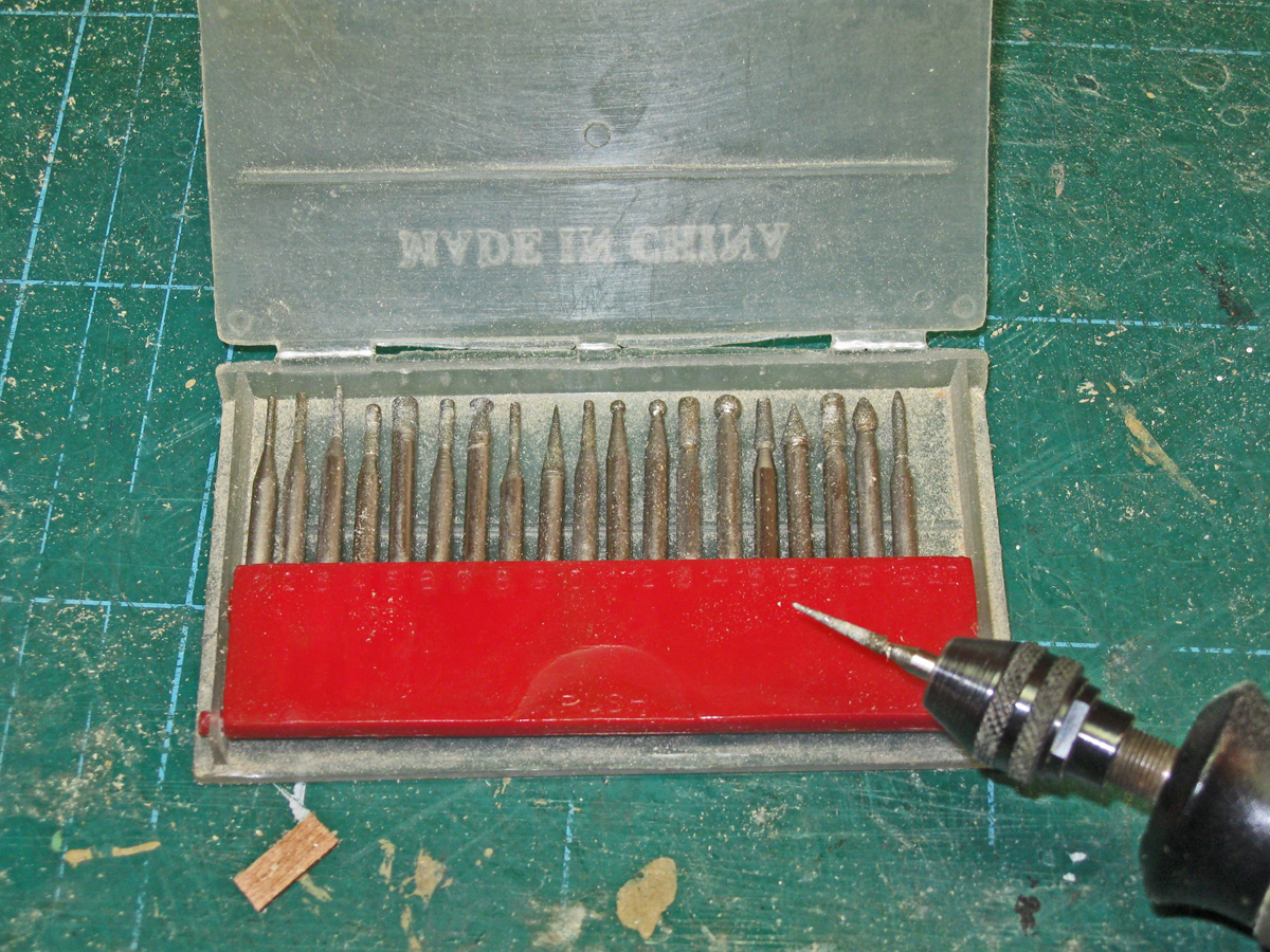
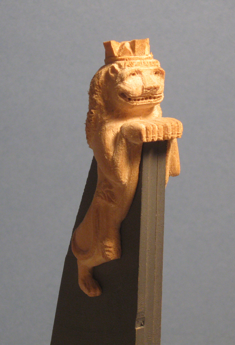
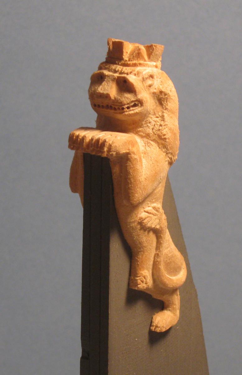
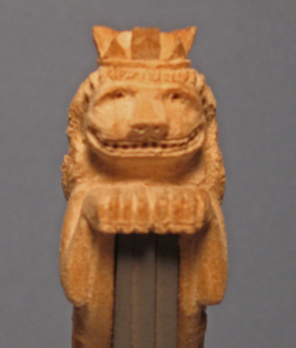
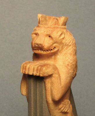
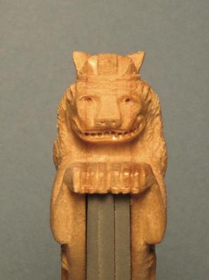
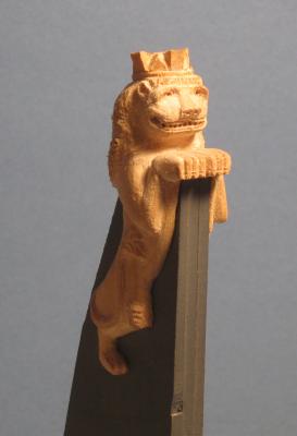
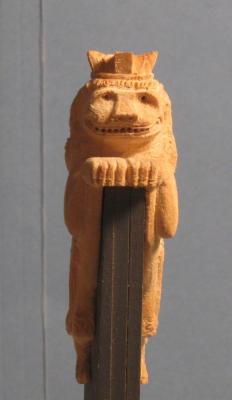
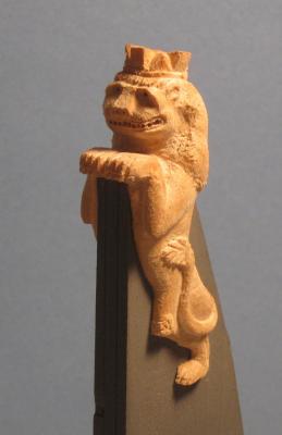
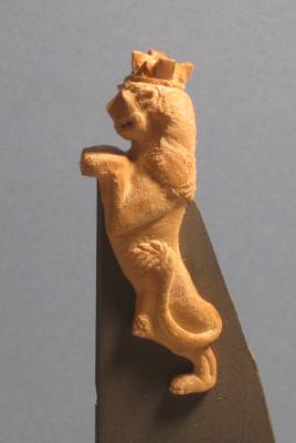
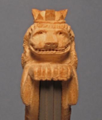
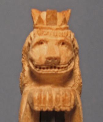
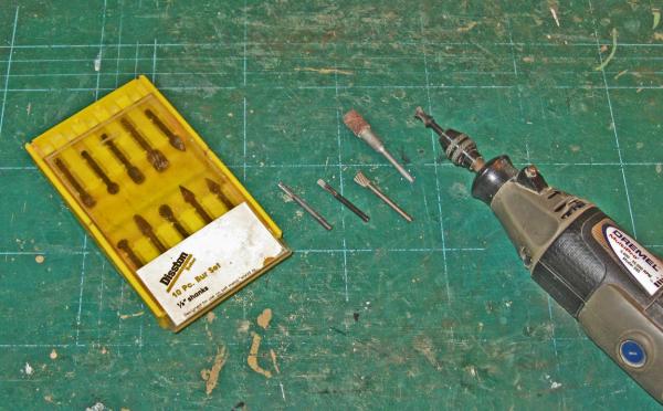
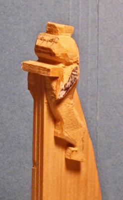
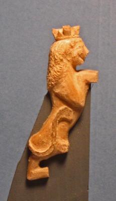
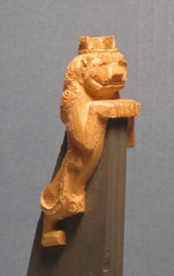
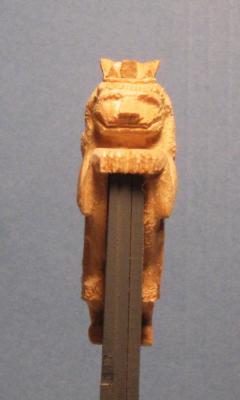
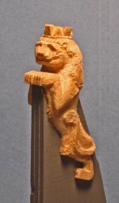
Hello again - Just back from the doctor, who says that a 'trigger finger' problem that I am having with my right thumb is related to the repetitive nature of the carving work. He told me to lay off for a while, and gave me a cortisone shot into the base of the thumb. Ouch ! And then it didn't work! I don't have much more to do on the first figurehead, so I am going to finish it in easy stages, then work on some larger pieces before going back to the second lion. Here is a short report on where I am now - This next phase of the carving is mostly a process of refining the shapes that were defined last time. For this I mostly use a series of diamond abrasive burrs of various shapes. Here is the set, purchased from Micro-Mark some time ago when Chinese tool makers hadn't started taking short cuts with quality. They have held up very well for more than a decade. The long cone in the Dremel is very useful. I use the point for lining out and small details, while the larger diameter of the base of the burr smooths and shapes larger surfaces. The carving process with these burrs is the same as for the larger bitts - I first define the edges and planes, then refine them by rounding the corners and adjusting the angles of the planes. Raised body parts like the tail and upper arm are given some dimensionality by undercutting them slightly to create a shadow line. All of the carving is all done by eye at this stage - the Michelangelo method - I just remove whatever doesn't look like the image in my head. Here are a series of shots with the work rotating starboard to port. The major issue right now is the shape of the head. It is still too broad. In some photos it looks more like a lizard than a lion. You can see that quite clearly in the first enlarged photo below. This was taken with the macro setting on the camera, and some of the problem is exaggerated, but you can see what I mean. In the lower photo I used Photoshop to narrow the image about 15%, and now it looks much more leonine. I will carve it down to get that general shape. If you haven't figured it out, the teeth are created by simply drilling a series of small holes which define the negative space between the teeth. I may use a small triangular file to refine them, or just leave them as is, since they are all but invisible uness a camera is used to magnify them. Happy Thanksgiving to all. Dan

- 241 replies
-
- 8
-
-
- queen annes revenge
- pirate
- (and 2 more)
-
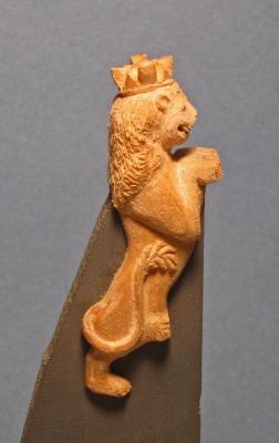
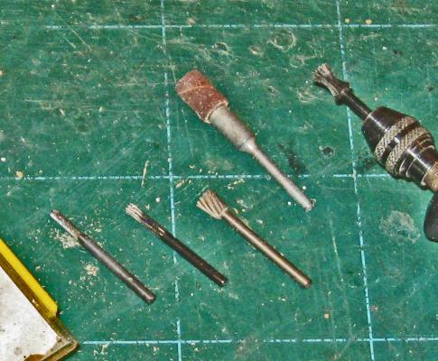
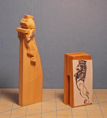
Hi all - Two days of carving and the first figurehead is rounding into shape. Here is how I am going about it. I do almost all of my carving with a rotary tool and a series of ever smaller burrs and bitts. Here they are for the first stage of the carving. It includes a 1/4" diameter sanding sleeve for the Dremel plus a set of Disston burrs. Over the years I have added to the set when I found other shapes that could be useful. Here are the ones I use most often. The sanding sleeve is at the top. From left to right we have a straight bit with a rounded tip; a straight bit with a square tip; a reverse cone; and in the Dremel is a sharp cornered reverse rounded cone. This last one is very useful for 'drawing' thin lines onto the wood that serve as landmarks for deeper carving with the other bitts. The first carving was done with the sanding sleeve to round off the square corners and planes left by the band saw, and to get the basic side to side shape. Now the arms are defined, which will fair into the basic shape of the lower body. The mane is rounded, which will frame the shape of the face. The tail was pencilled in on both sides and defined, which then set the depth of the lower body. The crown was detailed, which adjusts the top of the mane. The mane was given its initial texture, which then required reducing the height of the shoulder, etc. etc. This is how I carve, with each step or detail that is worked on leading to a further defining of the adjacent detail. So here is the current look of the first figurehead. The head is still too broad, but that is OK, as it gives me the depth of material that can be carved away for the final detailing of the face. Next time, the final detailing. Be well Dan
- 241 replies
-
- 7
-
-
- queen annes revenge
- pirate
- (and 2 more)
-
Bill - Happy to be of any help along the way. Best of success with the project. Maybe you can post some of your work as you go along. Dan
-
HI Bill - I'm not sure that any of the kits that you mention would be a good starting point for a QAR model. All are either too late, have only 2 masts, or are much larger ships. Any conversion would involve huge amounts of bashing. Looking around, I saw the Rattlesnake. Although she was American and about 75 years later than QAR, she mounts the same 10 main guns per side and her dimensions are very similar. She has a similar fine entry at the bow although her midships look narrower than QAR. You will have to build a square tuck stern and quarterdeck, but it should get you going in the right direction. Hope that helps. Dan