shipmodel
-
Posts
941 -
Joined
-
Last visited
Content Type
Profiles
Forums
Gallery
Events
Everything posted by shipmodel
-
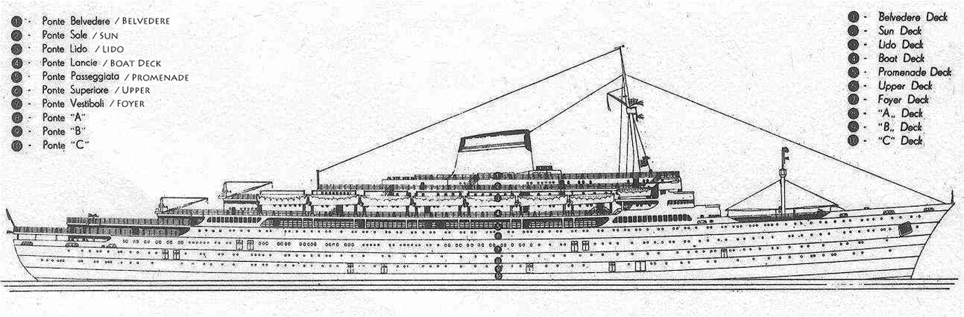
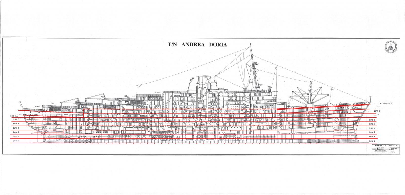
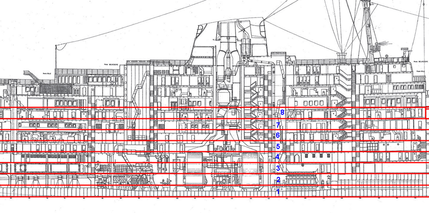
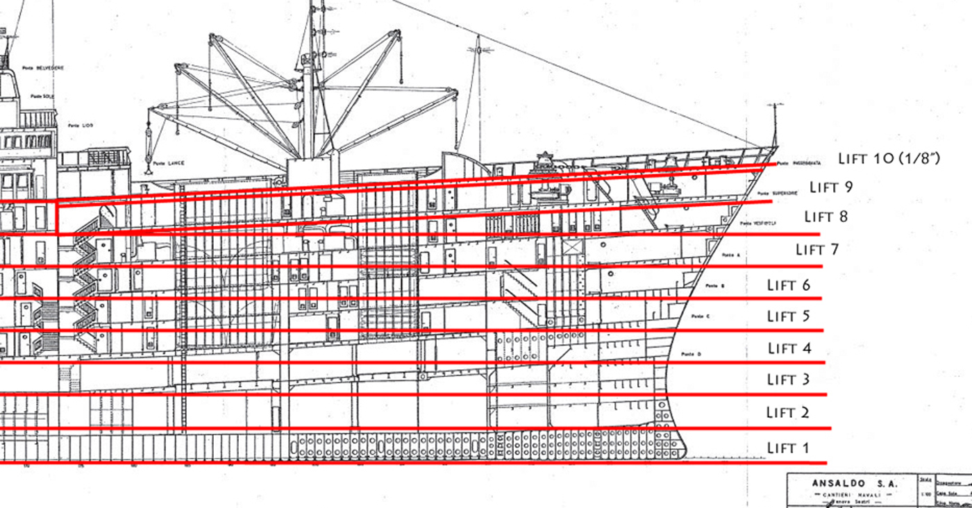
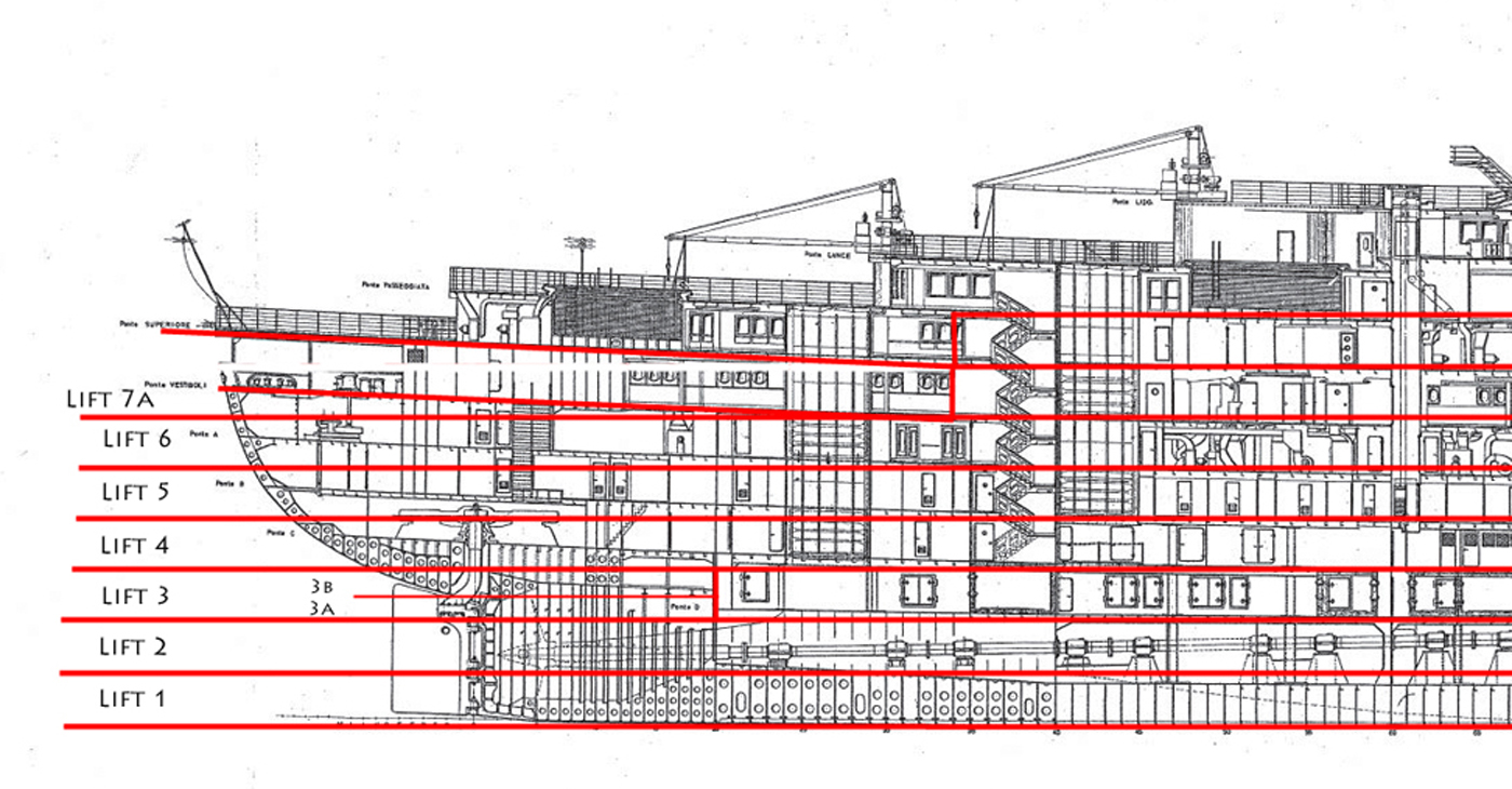
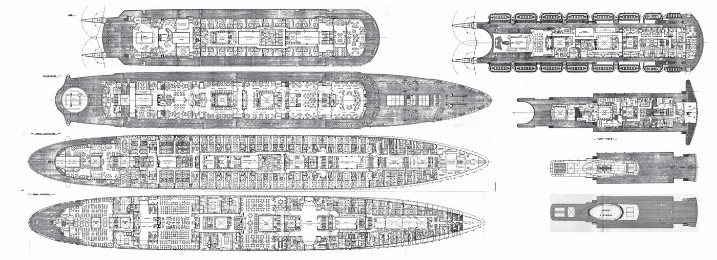
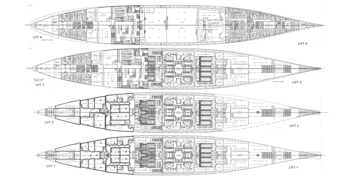
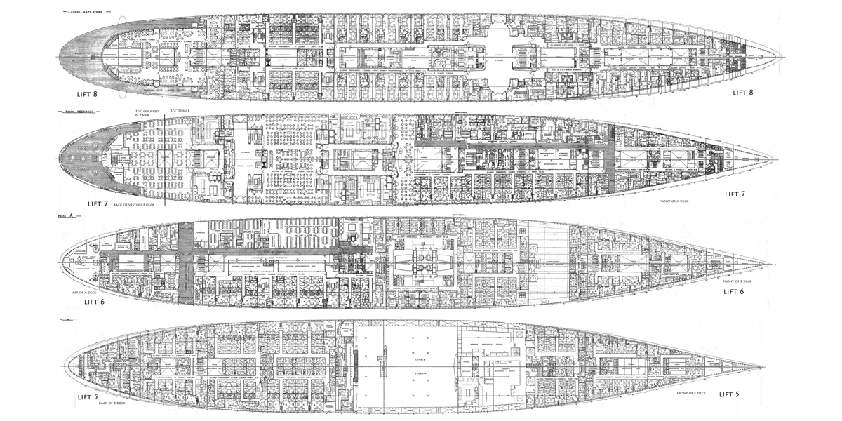
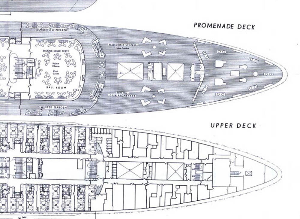
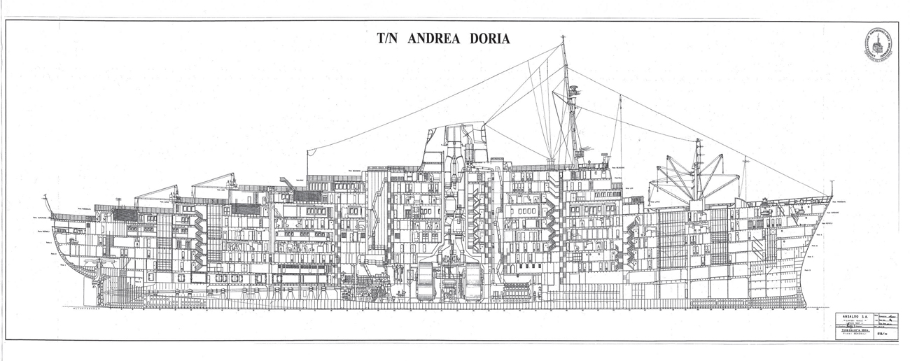
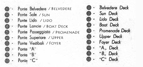
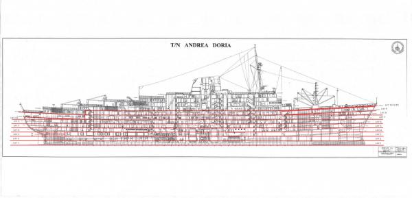
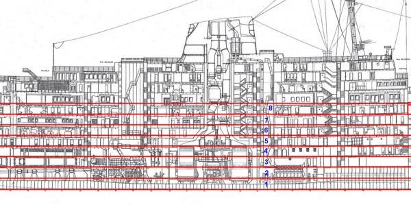
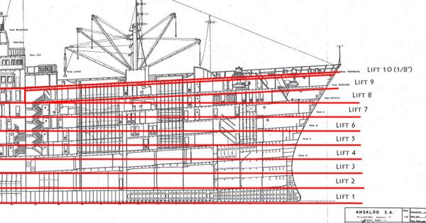
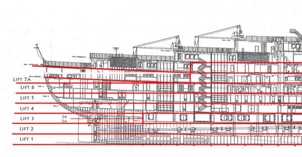
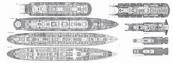
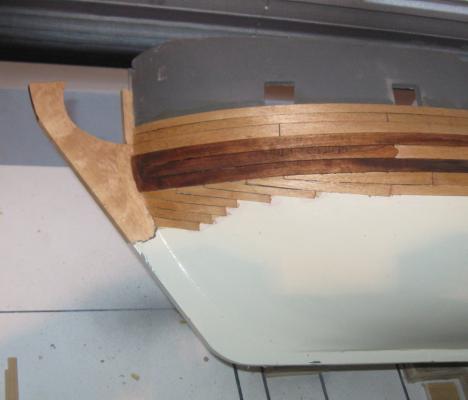
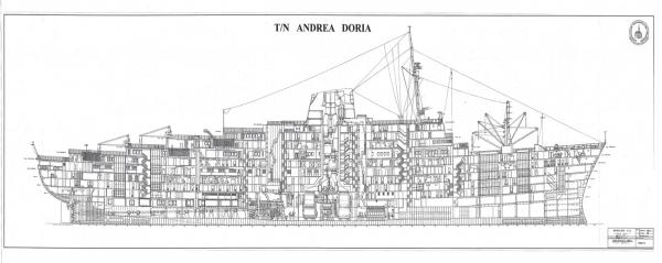
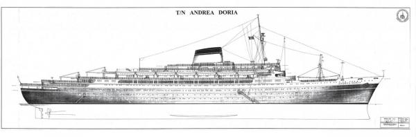
 Build log 2 – plans and lifts Thanks for joining me and for the likes and comments. She is an elegant liner and should make a sweet model if I am careful. Now that I had the paper plans in hand I took them to my local blueprint copy shop. For not a lot of money they digitized each sheet at 300 dpi. Since the sheets were 4 feet long and 2 feet wide, this made for some pretty large files, but well within my computer’s capacity. It did mean that they take a while to open in Photoshop, but that was a minor inconvenience. I also took some of the plans from the internet and used them for planning. The first of these was the exterior hull with the deck locations indicated in both French and English. This was taken from the deck plans poster, so I did not completely trust it, but it served as a rough guide to the overall appearance for preliminary planning purposes. First, the drawing had to be resized. I used the known LOA dimension of the Andrea Doria which is 213.80 meters, or 701.5 feet. Scaled down to 1:192 this meant that the model would be 1,113.54 millimeters, or 43.84 inches long. There is a ruler function in Photoshop and it was used to enlarge the image until the drawing was the same size as the model would be. Once adjusted for length it revealed that the individual decks were, with one exception, just under 5/8” tall on the plans (15mm), or 9.5 feet in scale. This would work out well, as I could build the upper decks up from ½” tall deckhouses and 3/32” caps or roofs. The lower hull would be built up from just the ½” layers since they did not have to match the actual height of the decks. With that decided, I could start to see where and how to divide up the hull into lifts. I began with the longitudinal cross section from the ANB plans. It was measured in Photoshop and adjusted as needed. Then it was overlaid with lines indicating the individual lifts. But there was a problem. The lifts would be exactly horizontal, while the deck map showed a substantial amount of sheer for each deck, especially at the bow. The number and shape of the lifts had to take this into account. Amidships this was a simple process. Seven half-inch lifts would bring the model hull up to the level of the Upper Deck where the color scheme of the ship changes from black to white. This is an important line, visually, so I based my construction sequence around it. At the bow the rise in the sheer line meant that the color separation line was now eight lifts high and tipped up at a shallow angle. The plan shows my solution, which was to add a wedge shaped lift (Lift 8). At the stern the problems were a little more complex. It turned out that the rudder post was 2 ½ lifts tall. Above that the hull expanded quickly to the rounded counter and stern. This came up only 6 full lifts, then there was the open working deck, also tipped up by the sheer line. You can see how I planned to piece it all together, with the third lift divided into a 3A and 3B lifts of ¼” each, and a wedge shaped lift 7A. Now that I had the number and thickness of the lifts set, I had to determine their shapes accurately enough to cut out the wood. The first step was to resize the deck plans to match the cross section. For each deck the overall length was measured on the cross section. This was then used to adjust each deck plan as needed. Interestingly, I found that some of the paper plans were a little small and some were a little large. Without this step I might have ended up with some serious conflicts down the line. Once each deck plan had been resized they were combined in one master plan. Each was located using internal landmarks so I could scroll up or down to see what was above or below the adjacent deck. This would later be printed out by the blueprint people and used to build the upper decks and their details. But the deck plans did not match the lift plans. The rise in the sheer meant that deck C was located halfway up Lift 5 at the bow, but only halfway up Lift 4 at the stern. Although the lifts would be somewhat imprecise, this was too much to adjust during construction. So I took the master deck plan apart and, for Lift 4, married the forward section of the deck B plan to the aft section of the deck C plan. The combined lift was then adjusted to the measured length of the lift from the cross-section. This was a lot of work, but at the end I had a set of lift plans that I was confident were close to the dimensions and shapes needed for the hull. You can also see where, for the two lowest lifts, I penciled in some extra material at the bow for the bulb at the keel. This was done by eye and would be shaped according to the photographs, as I never did locate an acceptable plan that showed this feature. Next time, I start cutting wood. Be well Dan
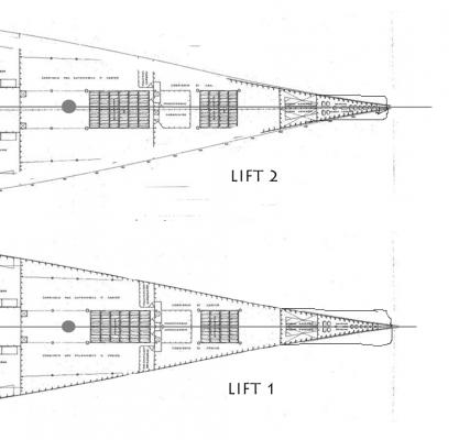


- 108 replies
-
- 11
-

-
- andrea doria
- ocean liner
- (and 1 more)
-
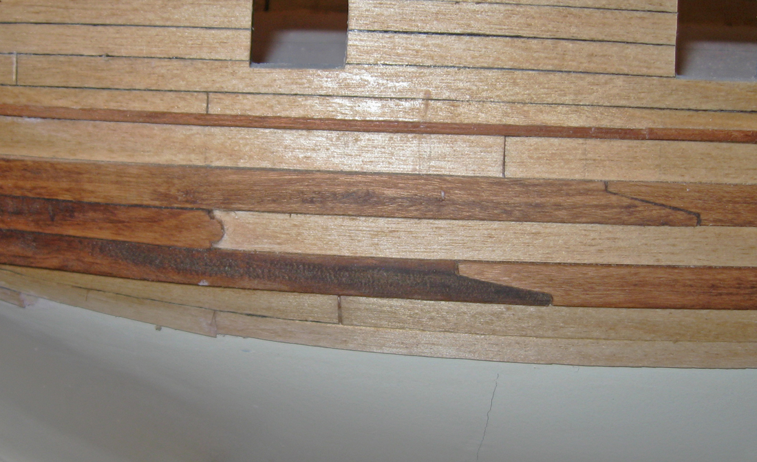
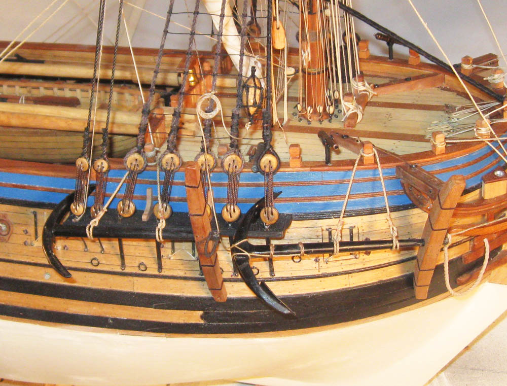
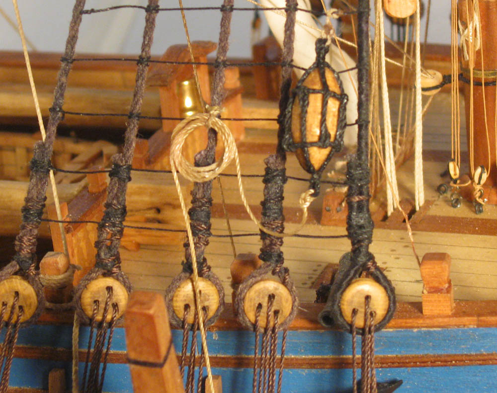
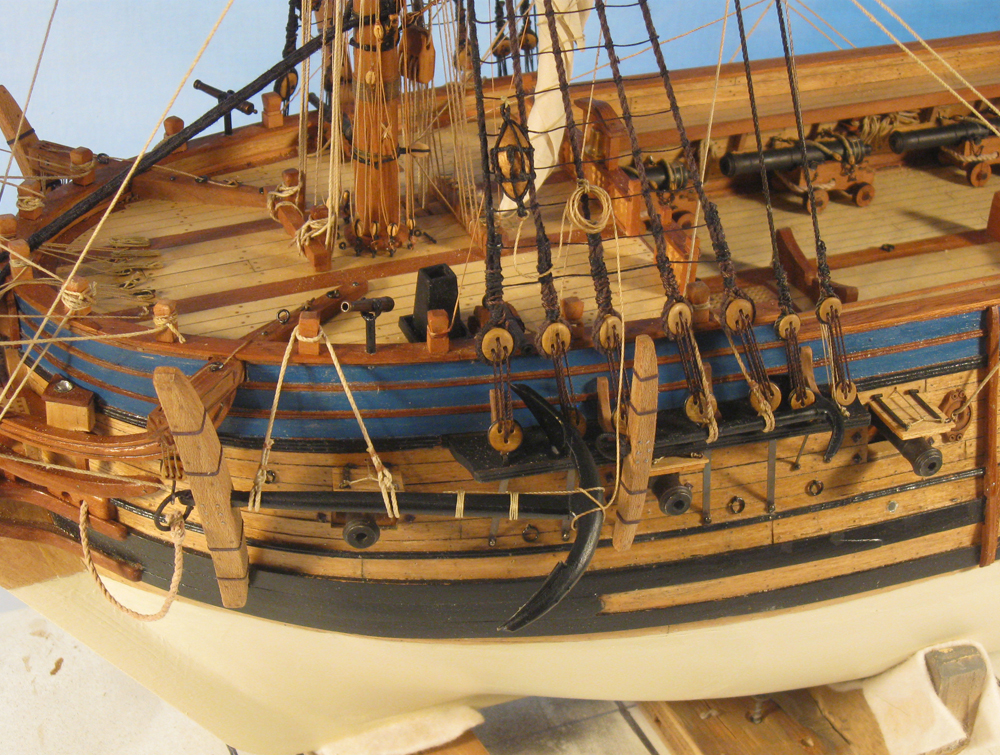
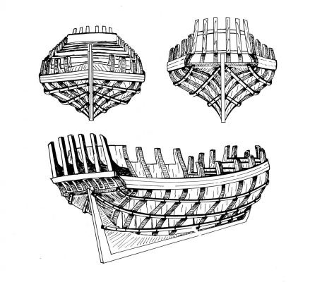
Mobbsie, Peter - Yes, the decorative way the wale is fashioned in French ships is related to anchor stowage. The French stiffened their longer, wider (compared to English designs) hulls by making their wales thicker and in several bands. Between the bands the hull planking was thinner, creating a step up to the wale. Where the anchor was hauled up for stowage the side point of the fluke could catch on it and rip up the wood. So at the bow the thinner middle planking was exchanged for thicker stuff that created a smooth surface for the fluke to slide on. Being French, where the thicker stuff ended, it was shaped in a stylish manner rather than just a functional end. Here are two photos of the element from the QAR project . Hope that helps Dan

-
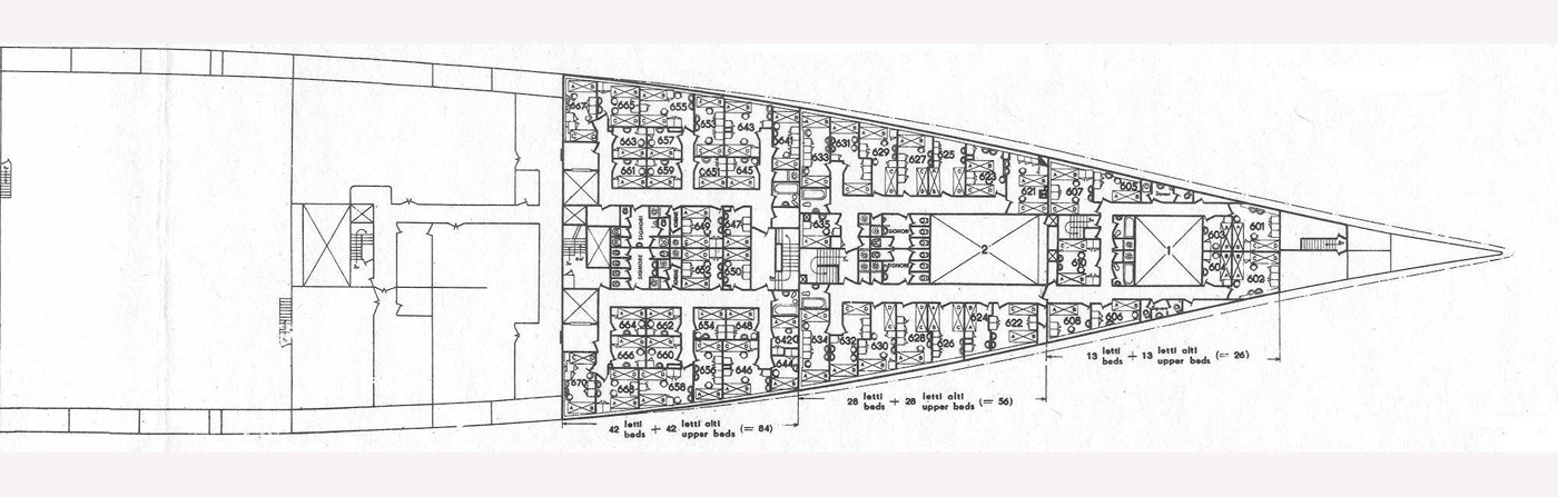
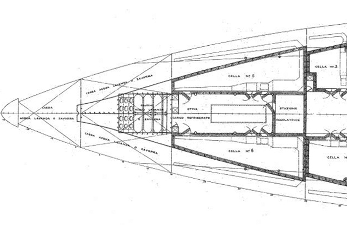
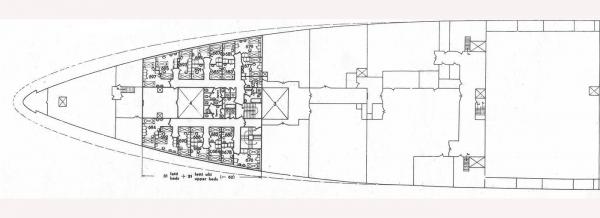
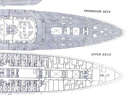
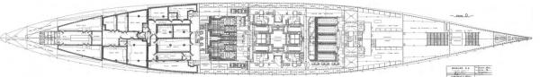
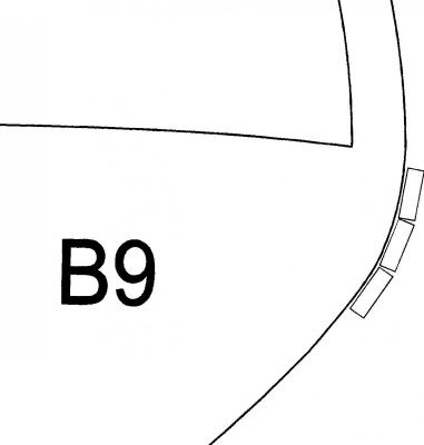
Hi Ben - Thanks for the SNAME article. It detailed and confirmed what I had read before. It will not affect the actual building of the model, but more information is always better than less. I looked again at the plans and the photographs. Some of the photos look like a straight sided hull, while others could have some slight tumblehome. But the deck plans do not show any indication of tumblehome. The breadth of the ship on the D deck is the same as on A deck. That may be from my digital manipulations (more on that in build log 2), but seems to be consistent. Also, each deck plan shows with a dotted line how the ship widens as it goes up at the bow and stern, but there is no corresponding line inside the outer perimeter amidships to show any narrowing. Here is the plan for C deck, separated into bow and stern so they would be larger in this format. You can see that the outer line shows the hull amidships as a single narrow line, with no indication of doubling, which there would be if there were tumblehome. I feel pretty confident that if there were any tumblehome it was so slight that it could not be seen on a model at 1/192 scale. In any event, the hull is completed and can't be changed at this point, so that's my story and I'm sticking to it. Thanks to all for being a second, third and fourth pair of eyes to keep me on course. Dan Dan

- 108 replies
-
- 5
-
-
- andrea doria
- ocean liner
- (and 1 more)
-
Nils - Just linked to your log. What a wonderful model. I will be 'borrowing' a number of your techniques if I am ever asked to do a riveted hull. Fortunately, the Andrea Doria does not need them. It makes life a lot simpler. Congratulations on an excellent piece of work. Dan
- 113 replies
-
- 2
-
-
- heinrich kayser
- steamship
- (and 1 more)
-
Hi all - Glad to have you with me. Christiano, yes, those seem to be the plans that I have, and I paid about the same in USD. Nils, you spotted the "pear shape" too. It makes so much more sense to have a straight sided hull, and the photo seems to agree. Ben, I would like to read the SNAME article, just for completeness, so no rush and no pressure. Thanks. Be well Dan
- 108 replies
-
- 5
-
-
- andrea doria
- ocean liner
- (and 1 more)
-
Mark - Thanks for the link, but as you noticed Chuck sent me the instructions and I did make the link on my Signature page. And thanks again to all who liked or commented on this build. I hope you get as much enjoyment out of following the build of the Doria. Be well Dan
- 241 replies
-
- 1
-
-
- queen annes revenge
- pirate
- (and 2 more)
-
Hi all - I have started a new scratch build log for my next model, the SS Andrea Doria (1952) in 1/16" scale. I will be setting up a link to it on my Signature page, once Chuck reminds me how to do it, but for now you can get it here: http://modelshipworld.com/index.php/topic/10963-ss-andrea-doria-1952-by-shipmodel-116-scale/ Be well Dan
- 241 replies
-
- 1
-
-
- queen annes revenge
- pirate
- (and 2 more)
-
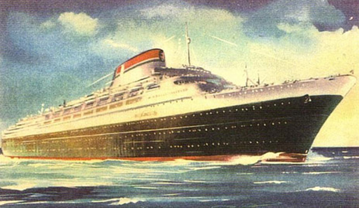
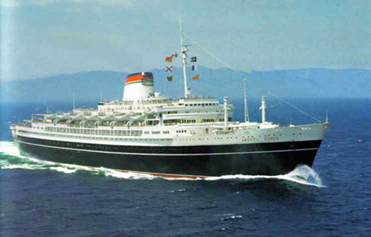
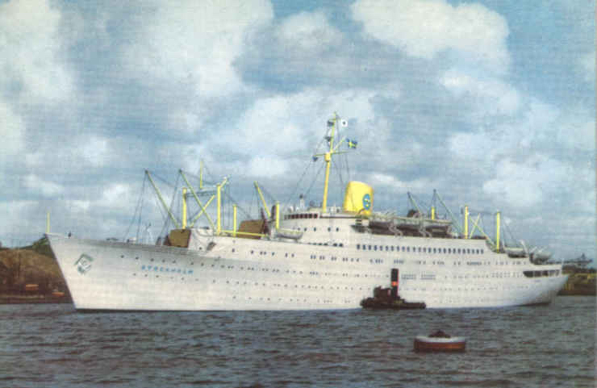
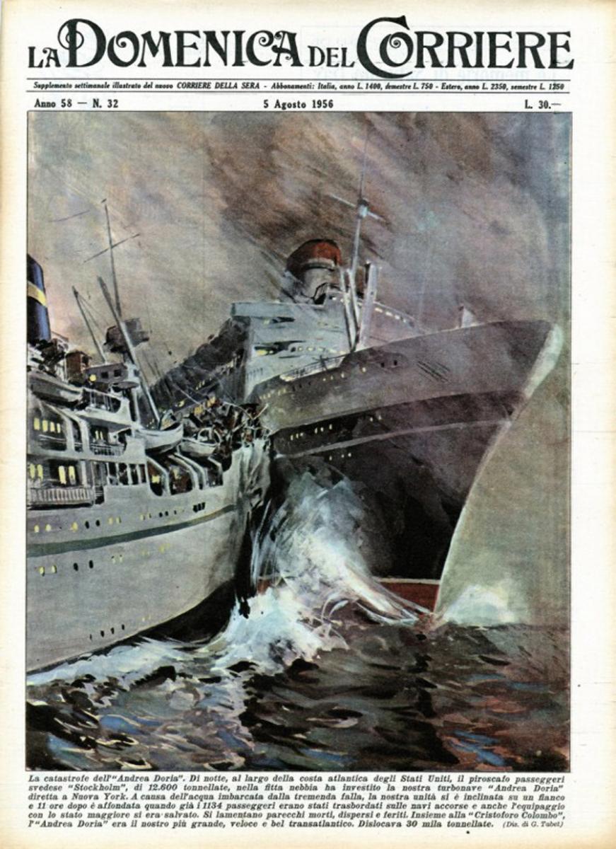
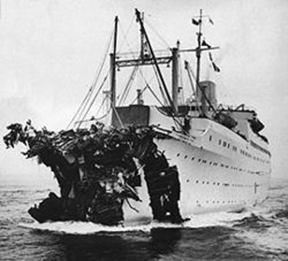
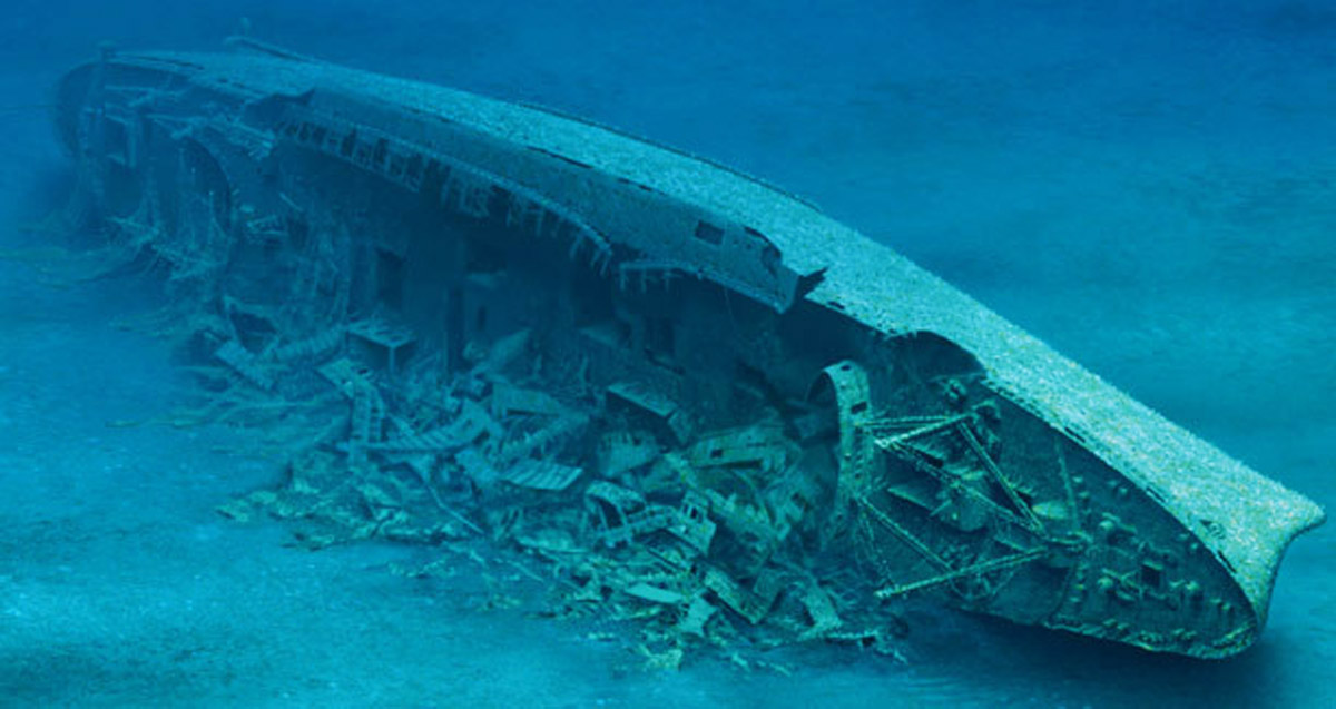
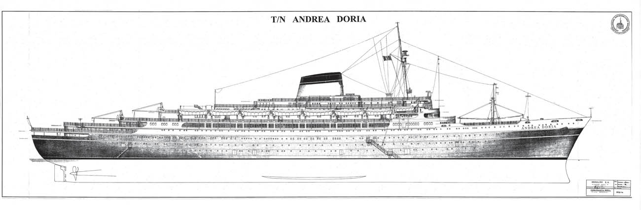
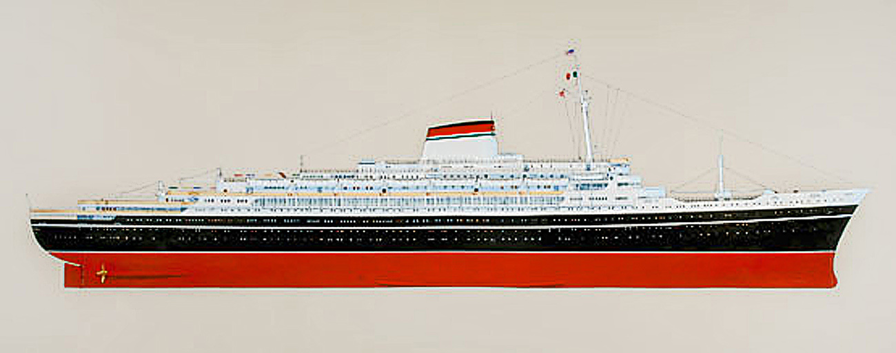
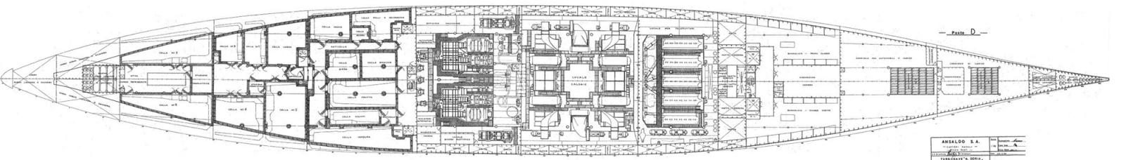
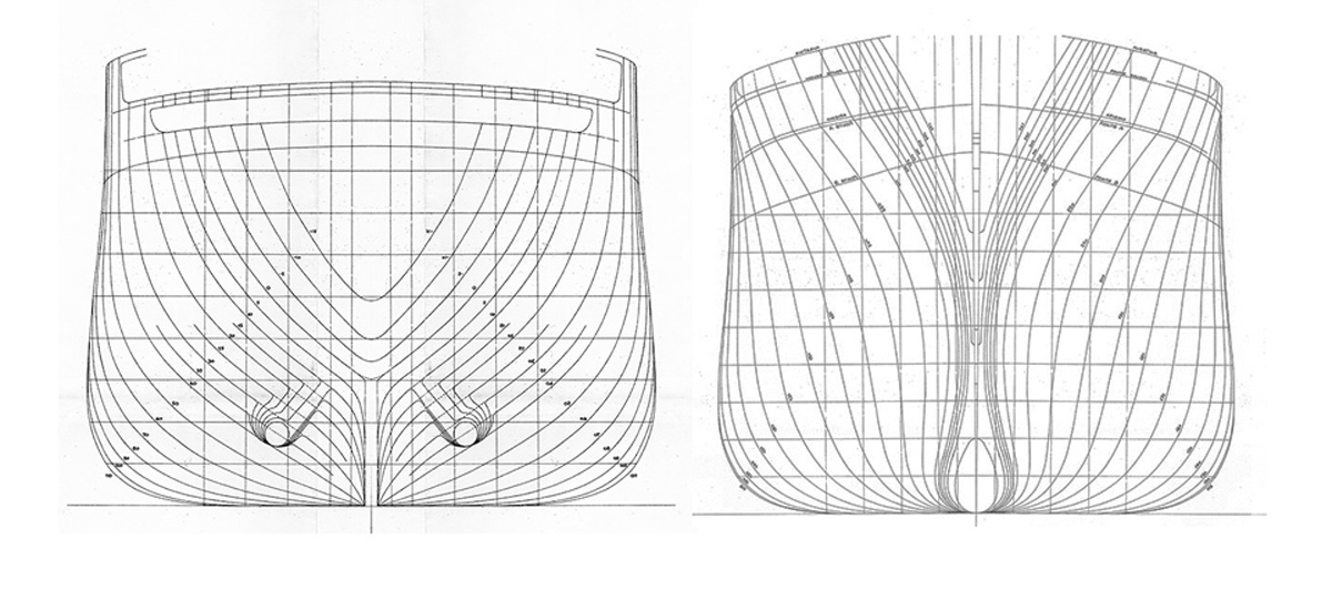
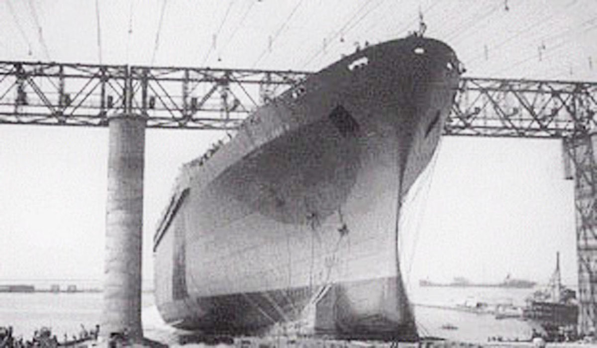
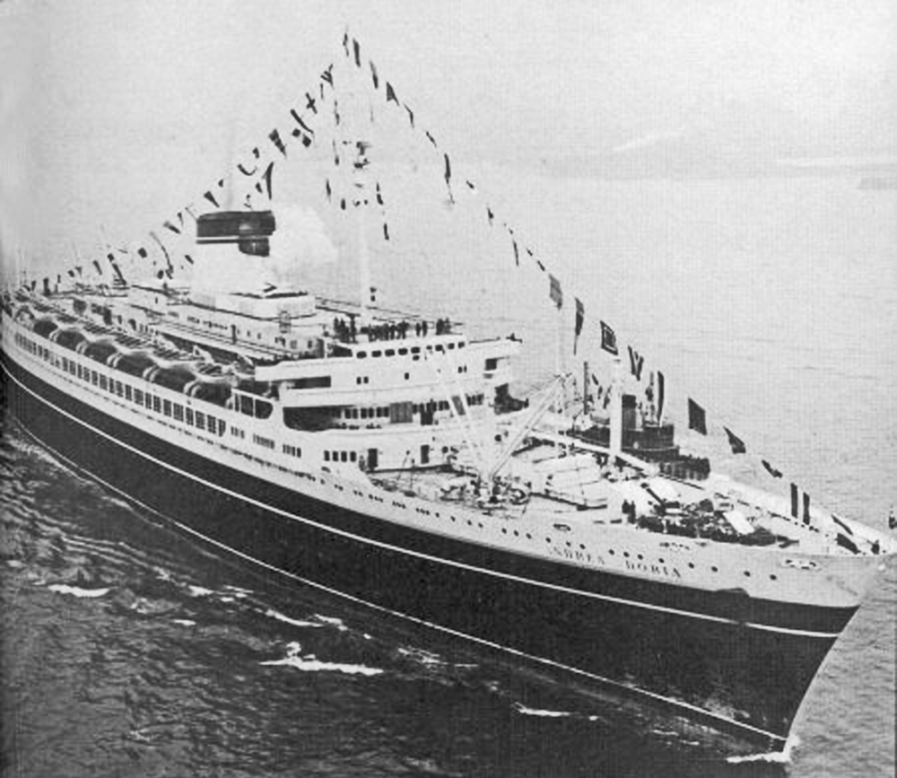
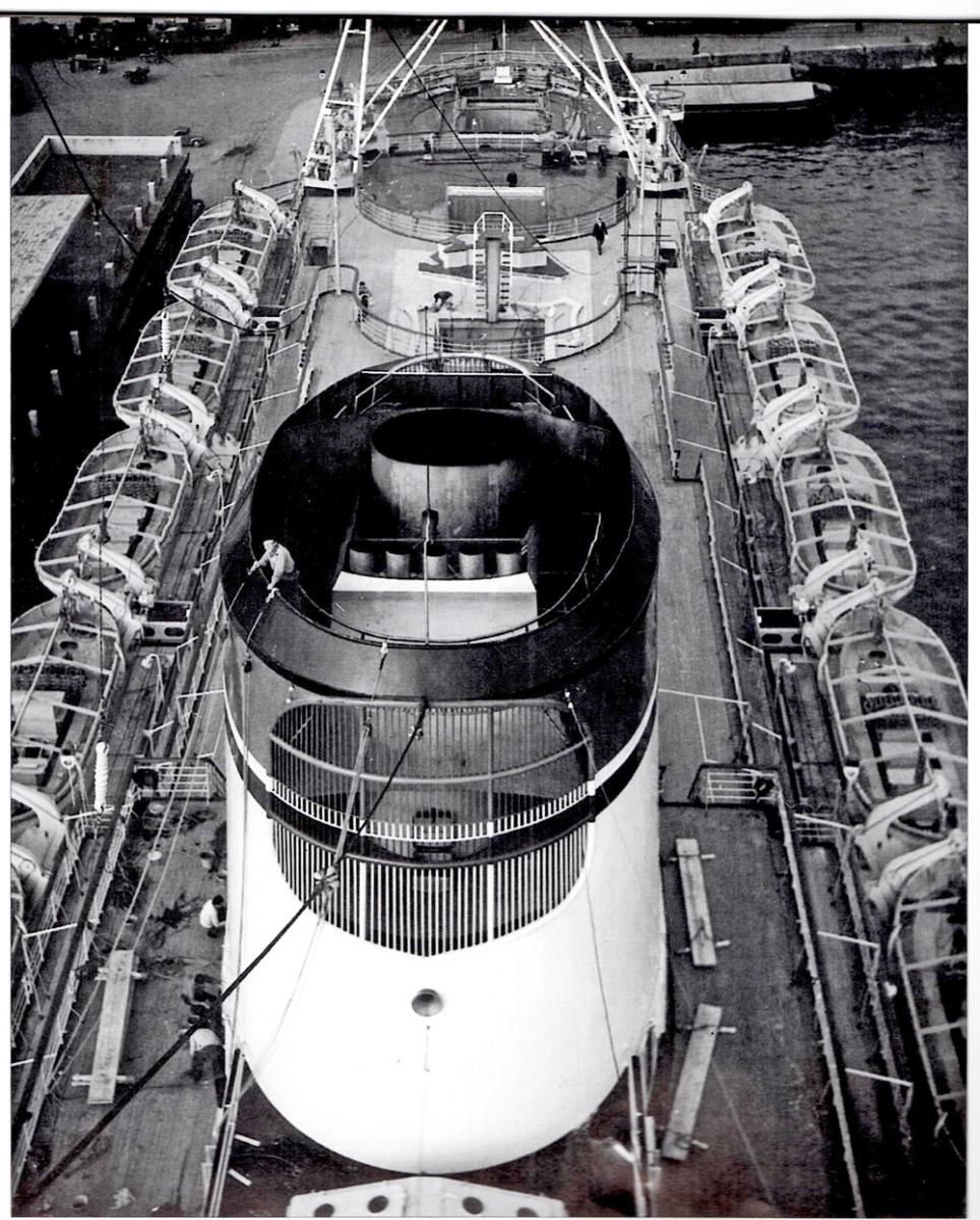
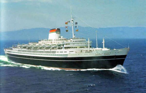
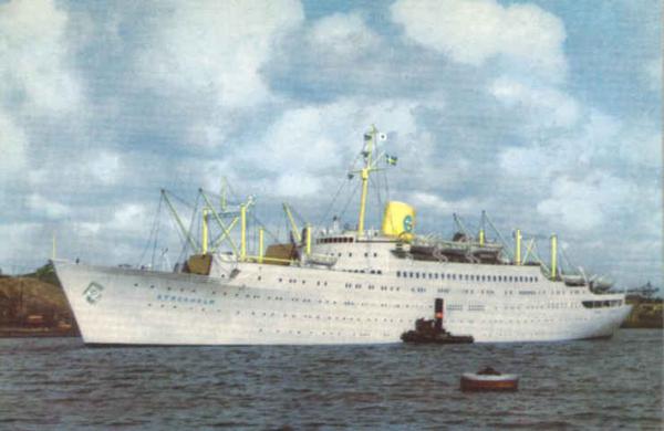
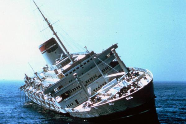
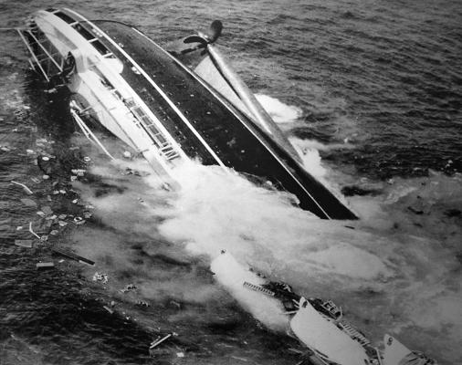
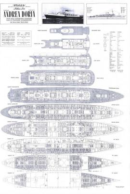
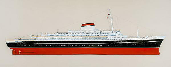
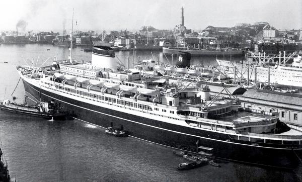
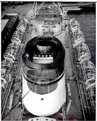
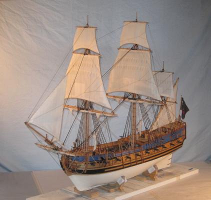
SS ANDREA DORIA (1952) Good day to all, especially those who followed my build log of the Queen Anne's Revenge (1710). I hope you will enjoy this one as well, and I look forward to your comments and critiques. This project is another large jump across time and techniques. It is the ocean liner SS Andrea Doria, the pride of the postwar Italian Line. Her likeness will be built to the scale of 1/16” = 1’ and will reflect her appearance at the height of her service life, the fateful night of July 25, 1956. This is my fourth liner model and it uses many of the techniques that I have developed for this type of ship. Some, I hope, can have broader applications, so even if you are only into sailing ships you are most welcome to pull up a chair and grab some popcorn. The essential elements of the model will be scratch built. This includes the large components such as the hull, decks, superstructures, and funnel, as well as the complex and unique elements such as the cargo cranes and swimming pools. But for some simple fittings aftermarket castings are acceptable as long as they are accurate or can be made so. Likewise, photoetched brass pieces such as railings will be used. The ship herself and her tragic story are known to many. SS Andrea Doria was the pride of the Italian merchant marine in a country struggling to renew its economy and reputation after WW II. Launched in 1951 she began service in 1953 for the Italian Line (Societa di Navigazione Italia). For more than three years she led her country’s liners as the largest and fastest ship in the fleet and one of the most elegant, with an outdoor swimming pool for each of the three classes of passenger. On the night of July 25, 1956 all that changed. Sailing towards New York City, eight days out of Genoa, she was running in heavy fog in the Labrador Current just south of Nantucket, Mass. Coming towards her was the liner SS Stockholm, outbound from New York for home. She was not in fog but in the dark night could not see either the fog or the Andrea Doria. Although both were spotted on the other’s radar, this was still a somewhat new technology and the positions and speeds of the ships were incorrectly plotted on each bridge. As a result, the ships turned towards each other rather than away. At 11:10 pm the icebreaker bow of the Stockholm sliced into the starboard side of the Doria and into dozens of passenger cabins with families asleep in their bunks. More importantly, it sliced into the engineering spaces below the waterline. SOS calls were immediately put out by both ships and soon a number of others were racing to the site of the collision. The Stockholm was still seaworthy, although her bow was completely crushed. 49 people, many of them children in third class, died immediately aboard the Andrea Doria, and five crewmen aboard the Stockholm. Yet, miraculously, 14 year old Linda Morgan was lifted from her bed and deposited into the wreckage of the Stockholm’s bow where she was found with only a broken arm and some scrapes. Andrea Doria soon began to list. This might not have been fatal because she had been designed with eleven watertight compartments with bulkheads that extended well above the waterline, only one of which had been breached in the initial collision. But five of the starboard fuel tanks were located there and they quickly filled with water. On the port side the tanks, which were empty at the end of the crossing, acted like balloons to raise that side. Even this might have been survivable, but a design flaw in an access tunnel allowed water to blast into one of the lower control rooms, and then into the generator room, cutting off power. Without power water ballast could not be shifted to port to compensate and the list steadily increased. Thirty minutes after the collision Captain Calamai ordered that the ship be abandoned. The list made it impossible to launch the port side lifeboats, but by reusing the starboard ones all of the passengers and crew were eventually evacuated to the safety of the rescuing ships. All, that is, but three who were fatally injured or died during the evacuation, bringing the final death toll to 57, the greatest loss of life in American waters in over 40 years. All through the night the list increased, and in the early morning hours she turned over and sank. The aerial photography of the sinking won a Pulitzer Prize for Harry Trask. Now she sits in about 190 feet of water, on her starboard side. This is too deep for the recreational diver but easily reachable on a mixed gas technical dive. It used to be a fairly well-visited site, but the deterioration of the wreck is so severe now that only the most experienced should think about trying it. The model begins, as all models do, with the plans and research. I was fortunate that a set of plans was available from Taubman’s Plans Service, a division of Loyalhannah Dockyard. Expensive, but if they were as advertised, they would be worth it. While waiting for them to arrive I went on an internet search. I quickly found a poster in quite high resolution on a public site which had been printed as an advertisement for the ship and which showed the cabins on the passenger decks and the layout of the upper decks and deck structures. Although I did not need to know the cabin locations or layouts, the poster was clearly copied from the engineering plans and was quite exact. However, the deck plans did not go below “C” deck just above the waterline and had no lengthwise or midships cross-sectional plans, so the shape of the lower hull was still a mystery. Also, due to the many times it was reproduced, I guess, the deck plans bent to starboard, a defect that had to be corrected. When the Taubman’s plans showed up they were a good news, bad news thing. They were clearly the engineering drawings, imprinted with the logo of the Bologne Society of Marine Architechts, the name of the builders and the date in 1952 when they were drawn. They included a longitudinal cross section that showed many of the deck house details including window and doorway locations, mast details and the interior of the large single funnel. An exterior illustration showed the locations of most of the portholes, doors and windows. This was supported by another illustration, this one in color, that was located on the net. But there was a plan for only one deck below the “C” deck, the “D” deck, although it had some indication of the hull shape of the rudder post below the counter. There was still no midship section, so the lower hull shape was still questionable. I did find some section plans on the internet, but they were redrawn for a model kit from Amati, and I had some questions about their accuracy, although they did show the bulb at the bow below the waterline, which did not appear on any of the other plans. However, when in doubt I always refer to photographs, if available. Here is one of the ship being launched, which I used to compare and contrast with the plans in hand. This was one of several thousand images that I viewed on the net. These were culled to about two hundred after eliminating duplicates and those that were of such low resolution to be useless. Of those, about three dozen were saved as the most relevant, useful, and detailed. Here are a few, and more will be posted as the areas of detail are built. More posted soon Dan


- 108 replies
-
- 17
-
-
- andrea doria
- ocean liner
- (and 1 more)
-
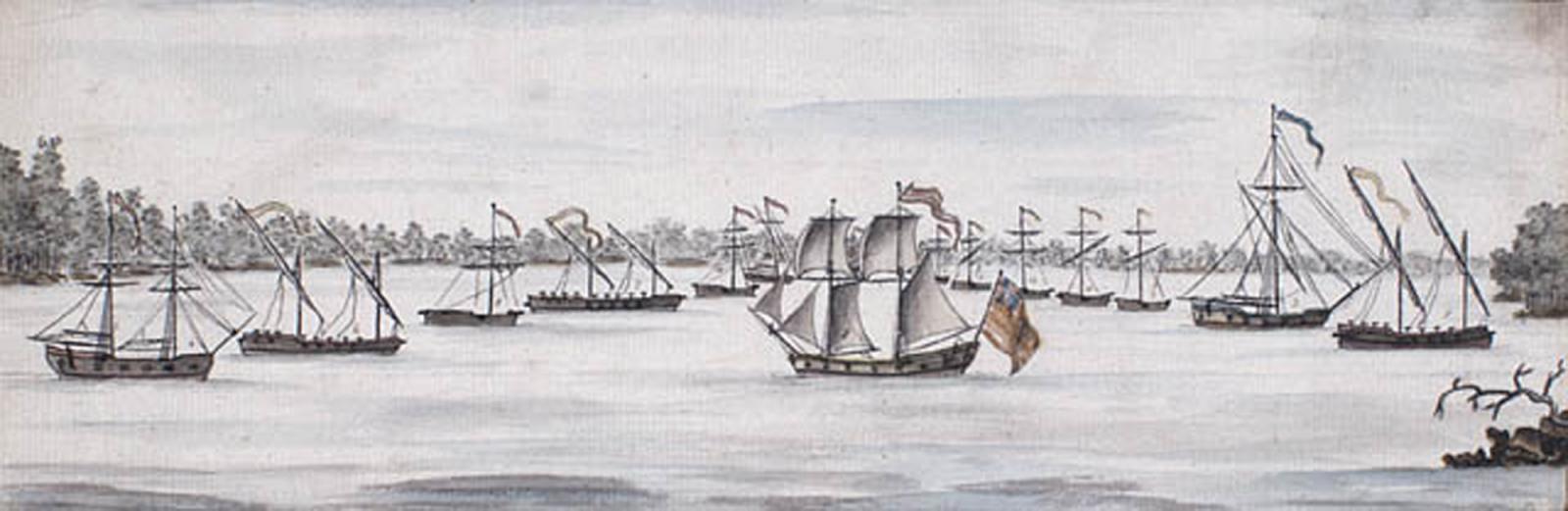
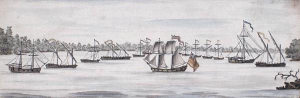
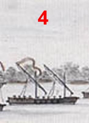
Hi Mike - Just found and read your build log. You have done a very creditable job on the model. Your stove and belowdecks details are top notch. You should be justly proud of your work. I did have one question, though. I looked at the plans and read the monograph by Jeff Stoudt and am confused by the number of gunports. The contemporary watercolor by Charles Randle seems to show only 5 open gunports in the waist, rather than the 9 along the length of the ship as shown on the plans. This agrees with the known armament of the Washington, which included only 10 long guns, which would have 5 mounted in each broadside. Since the ship was purpose built during the prior few months, wouldn't gunports match the available cannon? Why add gunports that weaken the structure and don't add anything to her fighting qualities? If all of the long guns are put on one broadside surely their weight would tip the ship down and make the guns unusable. I know that the Stoudt plans match those of Howard Chapelle (History of the American Sailing Navy, p. 108), but he is silent on his sources. There is a reference to the lines of the Washington being taken off after her capture, but I have never seen them reproduced. Do you, or does anyone reading this, have any thoughts about this question? Thanks Dan
- 175 replies
-
- 3
-
-
- washington
- galley
- (and 1 more)
-
Hi Mark - Yes, 100% better, but not quite there yet, to my eye. Go back to the photos of the model that Druxey sent you and compare the turn of the planks there to yours. I believe that the curve is less acute. You can see the sense in having a shallow curve for two reasons. First, a sharp curve here will create an eddy behind itself which increases drag. Those old shipwrights may not have had the mathematics to describe the exact drag force, but they sure could observe the effect and take it into account. Those old shipyard workers would also have been much happier with less of a struggle to bend 3 or 4 inch thick planks around a tight curve. Don't worry about removing too much wood since you will be planking over your frames. You can even put in a filler piece if you need to. Getting the curve right on this model will guide you on the next one where you could leave the frames exposed. But you are clearly headed in the right direction on the learning curve and on the model. Well done. Dan
-
Hi Mark - Yes, much much improved. You can't go far wrong if you follow Druxey's suggestions. Your progress up the learning curve is well underway and you are going to be very happy that you took the step back before you took the next step forward. And a belated Happy Birthday. Dan
-
ROYAL CAROLINE 1749 by Doris - 1:40 - CARD
shipmodel replied to DORIS's topic in - Build logs for subjects built 1501 - 1750
Congratulations on completion, Doris. I have followed your build with great interest and admiration. The finished model is a miniature gem, and the interior spaces are spectacular. Best wishes for your new job and your next project. Be well Dan- 883 replies
-
- 1
-
-
- royal caroline
- ship of the line
- (and 1 more)
-
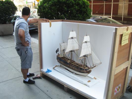
Thank you all for the likes and compliments, especially from those who followed the entire oddessy from the beginning. I am glad if any of the explanations of my own methods and techniques made another modeler's efforts a little easier. Here is a final photo of the model being crated for shipping. I hope to get down to the museum for the installation. If so, I'll post a photo or two. Be well Dan
- 241 replies
-
- 16
-
-
- queen annes revenge
- pirate
- (and 2 more)
-
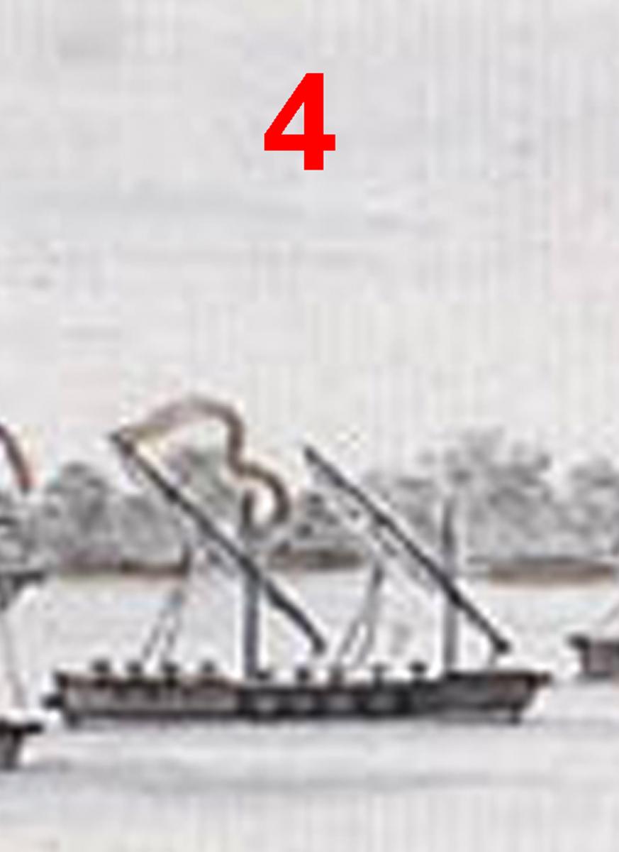
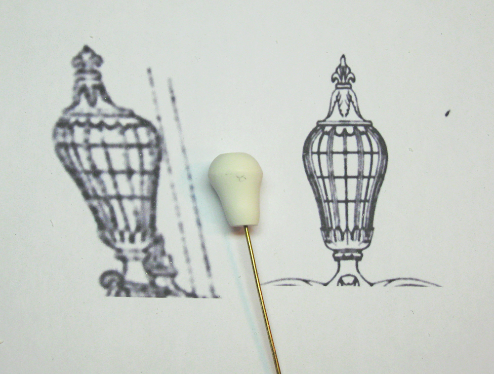
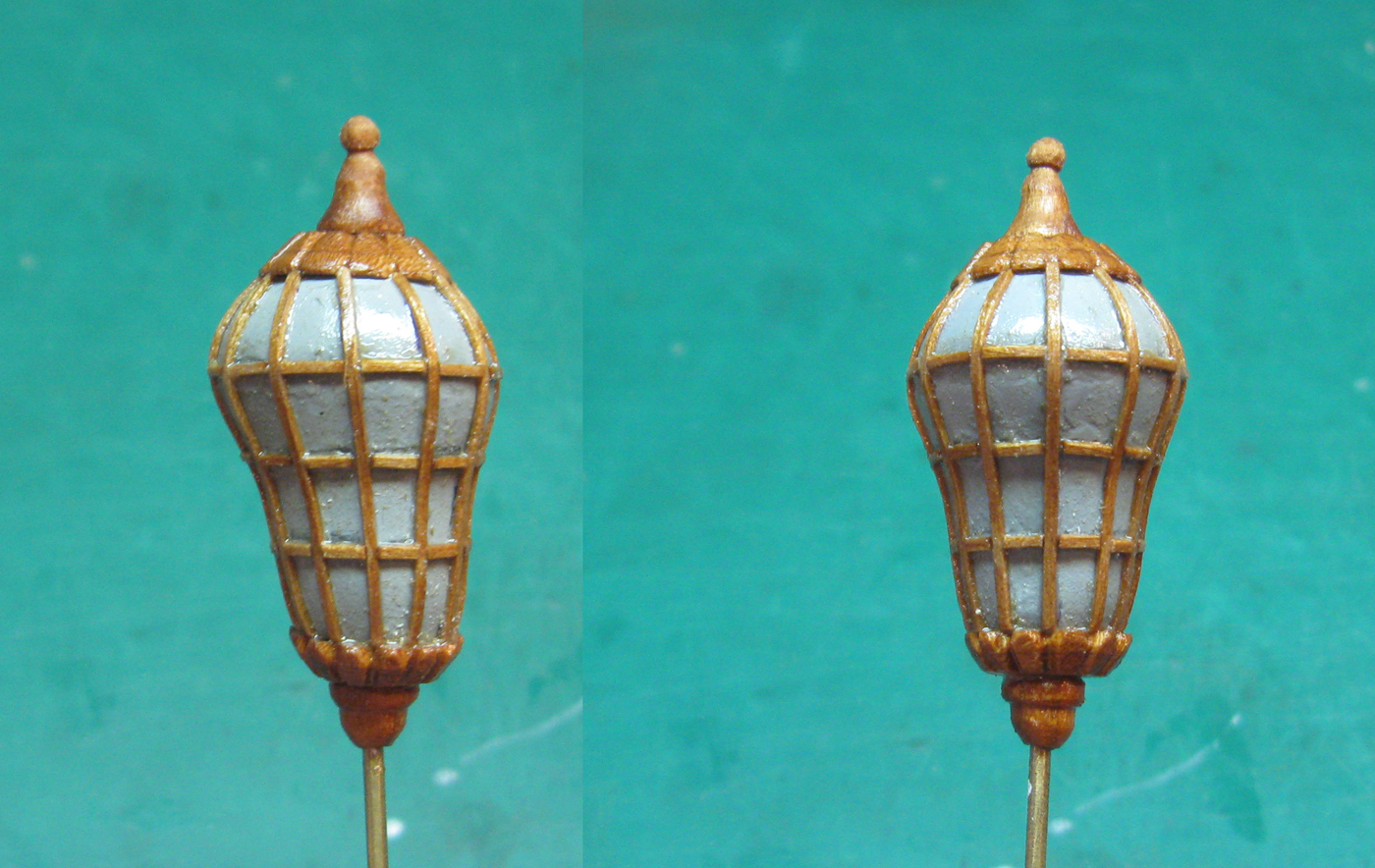
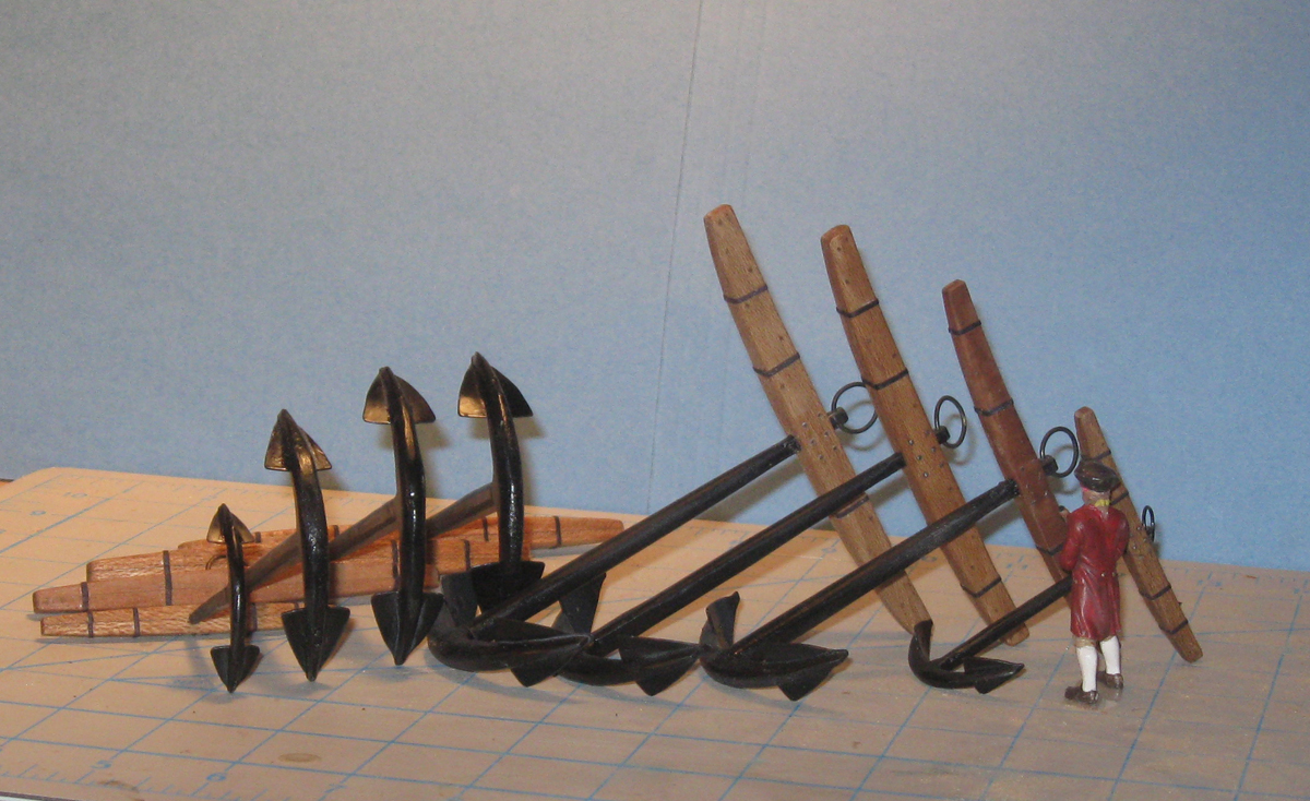
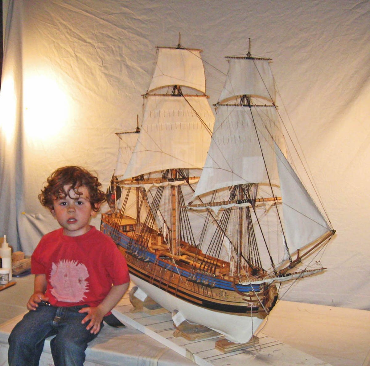
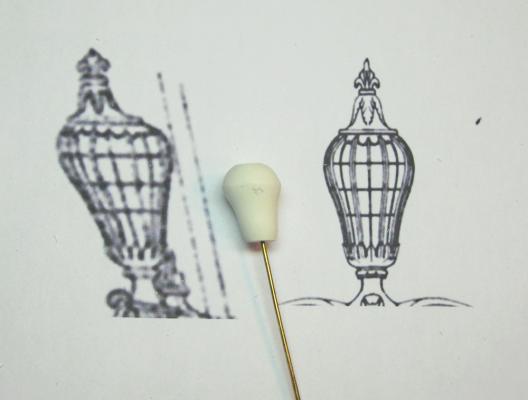
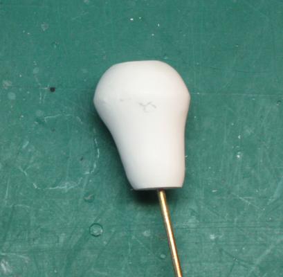
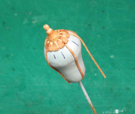
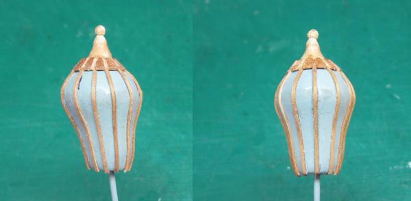
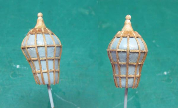
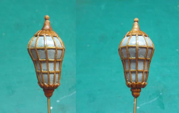
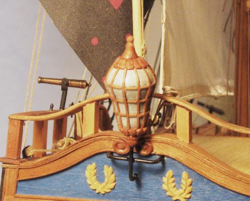
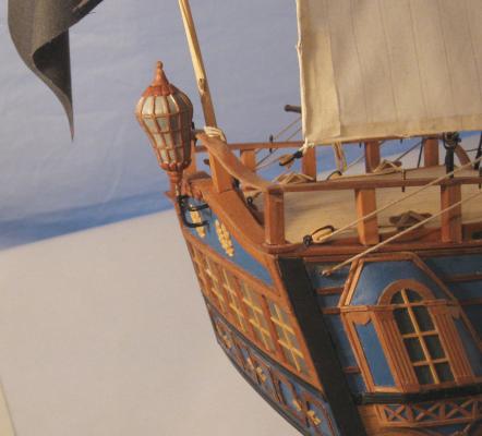
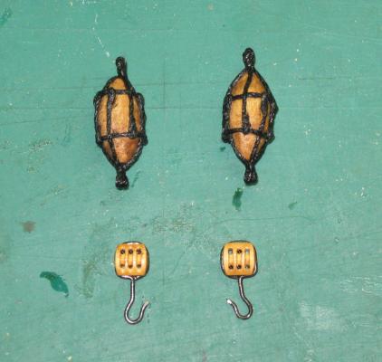
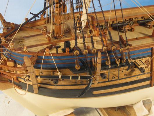
Hello again to all. Thanks for the likes and comments. I am glad that I can pass along some of the tips, tricks and techniques from my own teachers and from decades of trials and lots of errors along the way. This will be the final installment of this build log. The model is done and is waiting to be picked up for crating and delivery. The final touches include: the stern lantern; mounting the anchors and anchor buoys; fitting the ship's boat and the spare spars. The lantern was done in the round French fashion, rather than the hexagonal English style. This meant that I had to scratch build it, rather than buying one of the well-designed and detailed ones from Syren Models. In any event, here is how I went about it: The lantern is not really round so it cannot be simply turned to shape, as you can see from the reproduced sections of the plan it is skewed towards the stern. The central body was the most difficult to create. Attempts to carve wood and acrylic were both completely unsatisfactory. Starting from a cylindrical shape I could not get the proper angle to the lamp body. Instead, I tried Sculpey, a clay that is hardened by baking in an oven. After shaping it to the basic form by hand it was hardened according to the package directions. When cool and hard it was still easily refined and smoothed by sanding. The brass rod is for convenience in holding and shaping. 1 Here is a close-up of the body. Examining the photograph I saw that I still needed to bring down the sharp ridge between the upper and lower portions. 2 When the body was brought to shape it was given several coats of primer, then a final light grey color coat, with light sanding in between. The cap was carved from pear wood in a floral design. I tried to get 16 petals around the circumference, but this proved too fiddly, so I have 12. The finial on the top is turned from pear. The mullions to hold the glass are cherry veneer cut to 0.030” x 0.015” strips. Each was wet bent at the top end then glued in between the petals. When that was dry and hard the rest of the strip was glued down the body of the lantern. I put in the first four to quarter the body then marked out thirds in each section for the rest. 3 Here is a composite photo with two views of the lantern with all the vertical mullions installed. 4 The cross pieces were cut from the veneer strip and individually installed in three bands around the lantern. 5 A floral base was carved and a round drop at the bottom were made out of pear. The finished lantern was sanded to remove any sharp corners then finished with a light stain/neutral carrier mix. I let the stain pool a bit in the corners, which gave the panes some depth and shadow. Each section was filled with white glue which dried to create a glossy ‘glass’ pane. 6 Mounting hardware was fashioned from a 0.062” brass rod with two pieces soldered at right angles. The mount was bent and trimmed to fit a trio of holes in the stern. After blackening the mount was installed and the lantern fitted to it at an appropriate height. 7 And here is how the lantern fits in with the look of the rest of the stern. 8 Next I turned to the anchors. In an earlier segment I went through how I constructed them. Here are the two finished sets of four anchors for each model. 9 To hang them I needed a triple block for each of the largest ones which would be mounted at the catheads, as well as an anchor buoy for each. The blocks were made from 7mm triple blocks which were detailed by drilling a second set of line holes and rounding the resulting ‘sheave’ in the middle. The hook was bent up from 0.035” annealed iron wire with the shank wrapped around the block in a deepened strop groove. The buoy bodies were ¾” long, turned from maple. Two ropes were seized together forming a small loop and spot glued at either end. The lines were led down the body and under a cinch line about ¼ of the way from either end. The vertical lines were doubled back on themselves, glued and trimmed. 10 Here are the anchors mounted on the starboard side. They are the two middle sized ones. They are hung with strong lines from timberheads at the rail as well as the hooked block at the cathead. A sense of weight is imparted by hanging a weight from the anchor then stiffening the supporting lines with dilute white glue. 11 Here is the buoy tied to the shrouds with a loop of line that is ultimately secured to the anchor shank. 12 And here are the two on the port side similarly secured. These are the largest and smallest of the set. 13 The final tasks were to secure the ship’s boat in the waist and add two spare topmasts and large spars. These sit between the gaps in the rails at the edges of the foredeck and quarterdeck. 14 Various rope coils were added to each belaying point, the model was cleaned and a few spots of paint were touched up. So here she is, ready for pickup and shipping. 15 16 And one final photo of a future crewman, grandson Eli, who is almost four and already very interested in what his Poppy Dan does with his boats. . . 17 It was an interesting build, and radically increased my appreciation and respect for those modelers who rig sails. As always, questions, comments, and critiques are very welcome. Back soon with another project, the SS Andrea Doria in 1:200 scale. Till then, be well, Dan


- 241 replies
-
- 30
-
-

-
- queen annes revenge
- pirate
- (and 2 more)
-
Hi Jay - I don't think that you are missing anything, and it is probably my failure to explain properly in any case. We are both doing similar things to get a good result. You are planking in one direction towards a batten, while I plank in both directions towards a center. Like many tasks in ship model building, there are several ways to solve any particular problem. All of them are right, so long as the result is good. I looked at the log of your Connie build and you are clearly getting good results. Stick to what works for you. Be well Dan
-
Carl, George - You are both right. Spiling/planking is a complicated process. Even after doing it for 30 years I still have to take my time and agonize over the process. Sometimes planks that I thought were correct have to be stripped out and replaced. The problem is the shape of the hull with its compound curves, some of which change from convex to concave on the same rib and along the same planking strake. Yes, you can start with planks that are slightly wider than your measured marks, which works on the convex curves, but is wrong for the concave curves. My only point here is that you can't rely on measurements, no matter how precise. To get a smooth, straight, fair run for each strake the measurements are just the starting point. Each plank has to be shaped by eye and the battens used as adjustable guides, not inflexible borders. Fortunately, I had some good teachers, and now there is this entire wonderful community of modelers in the NRG and on MSW who are so generous with their time and knowledge. Be well Dan
-
Hi George - The problem is one of measurement. The thickness of the planking means that the distance around the curve on the outer surface of the planks is longer than the curve on the inner surface of the planks. If you measure your distances on the surface of the rib and divide by the number of planks, you will get a dimension that is smaller than you need to fill up the distance around the curve on the surface of the planks. When you bevel the edges to bring the planks together at the surface, they will no longer cover the full distance that you measured on the rib. To put in some numbers, let's say that the distance on the rib from wale to batten is 40mm. I decide to fill it with 8 plank of 5mm each. I cut the planks to that dimension and lay them in the space. I bevel the edges, which means the inside width of the plank is less than 5mm. Let's say that it is now 4.8mm. The 8 planks now cover only 38.4mm. There is a gap of 1.6mm. This would not be much of a problem if I was planking a cylinder, I could just add an extra plank as needed. But the uneven shape of the hull means that the gap will vary and therefore the line of the caulking seam will wander up and down, and the shape of the space still to be planked will no longer match the battens that were so carefully lined up. Does that make sense? Dan
-
Mark - Looks much better to my eye. Should fit well once you set the rest of your battens. As for exact plank widths and numbers, don't tie yourself to exact dimensions, they really can't be calculated. There is what I call the 3-dimensional problem. The widths you have measured are for the faces of the ribs. The planks have a definite thickness, so where they cover a convex surface the inside corners hit each other before the outer ones do, creating an unsightly gap. This is even more of a problem with French designs that have those large bulges at the waterline. To get a tight fit at the outer surface the solution is to bevel the edges of the planks, but then the inside width of the plank is less than the outer width, and no longer matches the measured dimensions. You can start with wider planks, but the variation changes depending on the curvature that is being covered. This changes from wale to keel and even along the length of one plank strake. My solution, which is just one of several that works, is to plank up from the keel and down from the wale at the same time. As you near the center all of the dimensions are recalculated after each plank strake is added. Eventually you reach a space that can be closed in by one or two final "shutter planks" that should look almost identical to those on either side. Practice on the tape and take your time. It will come together in a planking job that you will be proud of. You are making a very good start. Dan
-
Hi Mark - Welcome to the wacky and wonderful world of spiling. Although you can get lots of help from various books, and Jim Roberts' is one of the best, it is mostly a question of experience and eyeballing. One thing that Jim suggested when I was his pupil was to take strips of frosted tape and lay them flat on the hull till the area I was working on was completely covered. Like the planks, the tape will sweep up toward the wale with the curve of the hull and cover previous tape runs. This is a good thing. It shows how much the planks want to bend so I could start to judge how many stealers/drop planks I might need. Also, with the area completely taped I could line out the plank runs in pencil, making as many mistakes as I wanted without consequence. After a while I developed a good sense of how the hull wanted to be planked, and could then much more accurately position my battens to guide the actual wood planks. On the Licorne I have a feeling, and I could be wrong, that your first batten is too high (towards the keel) at the bow. Judging by eye, the remaining area from the batten to the keel is not wide enough and your lower planks could be crowded and narrow, The only way to be sure of this is to put in all of the battens that you want and then carefully examine them from dead ahead to see if they give you equal spacing. A similar thing goes on at the stern. Here is a drawing of what I mean. It is from Jim's book, although I have removed his text for clarity. Remember also that the garboard and first broad strake (the one next to the garboard) are wider than the rest of the planks, and your spiling/batten plan has to take this into account. This was probably a longer response than you wanted, but I hope that it helps. Dan
-
Hi Mark - Coming along quite nicely. I can see how your planking skills are improving all the time as you get more experience and work your way up the learning curve. As for sequencing, I recommend that you plank the stern first. This is how it was done in actual practice, so the run of the hull planks would overlap the hood ends of the stern planking, reducing the chance that water action would loosen the stern planks. It is also easier to do, because you can sand the ends of the stern planks flush with the final ribs, then simply run the hull planks over and past them before trimming and sanding flush with the face of the stern planks. If you have Zu Mondfeld's book, look at his discussion of stern planking (pages 96-97 in my edition). Looking forward to watching you progress. Dan .
-
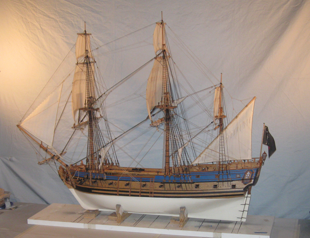
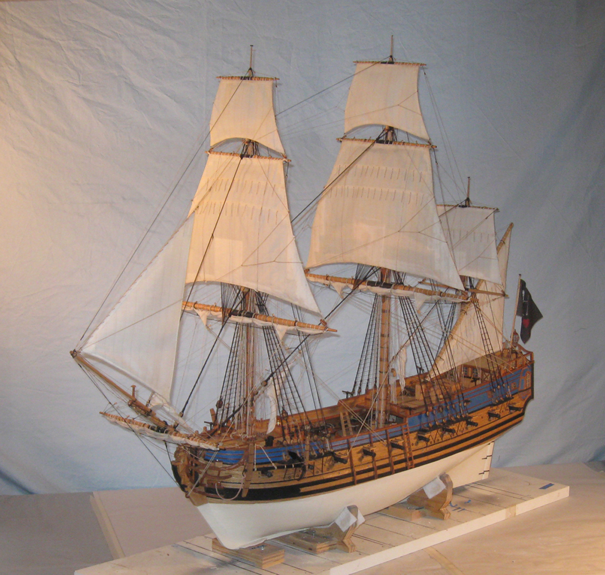
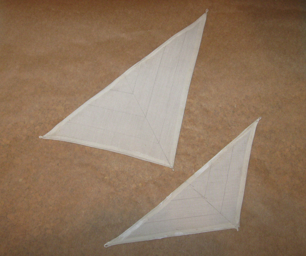
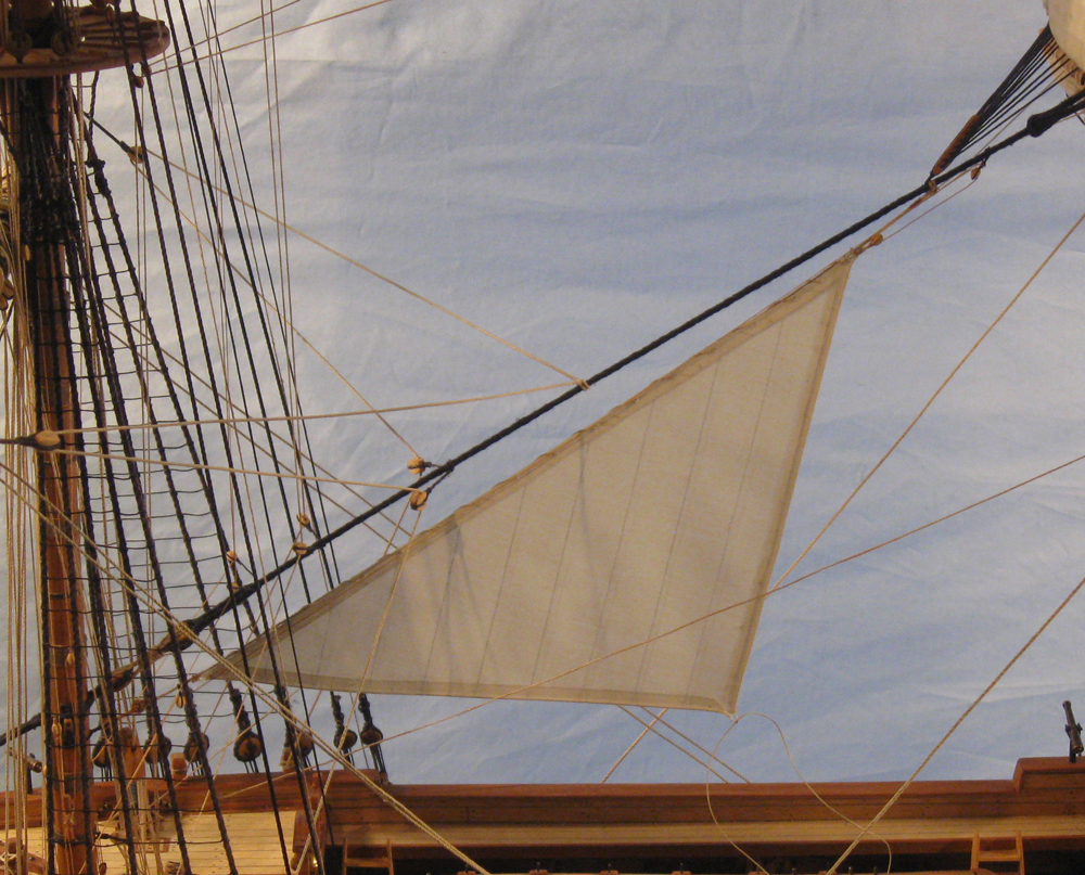
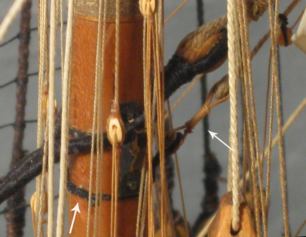
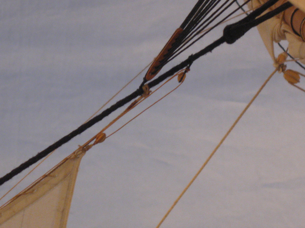
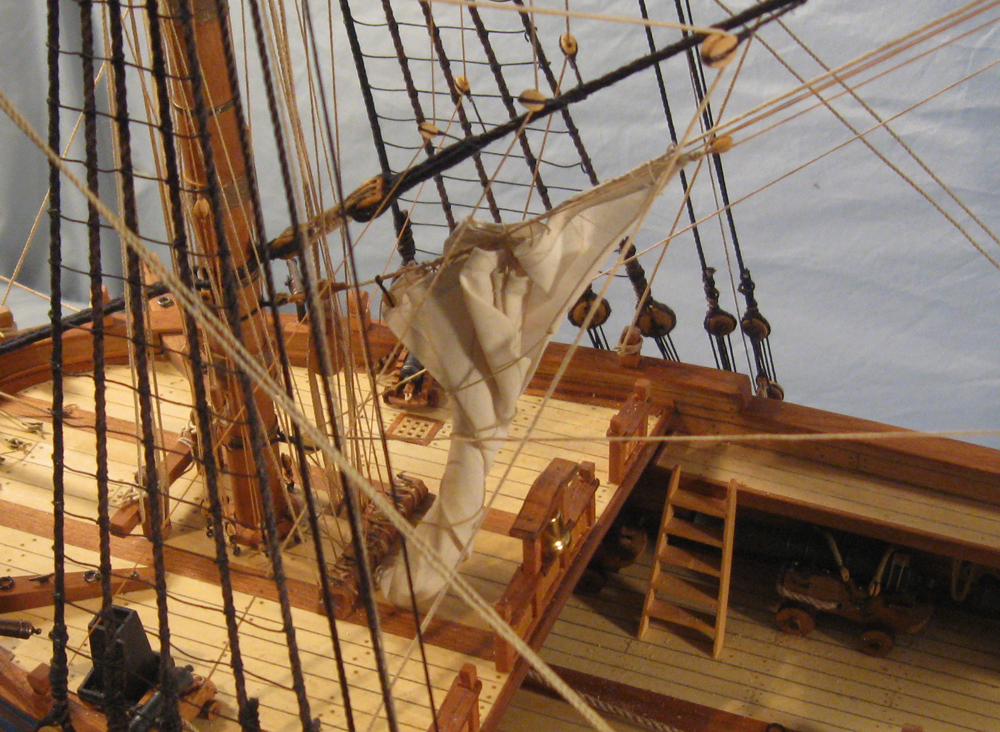
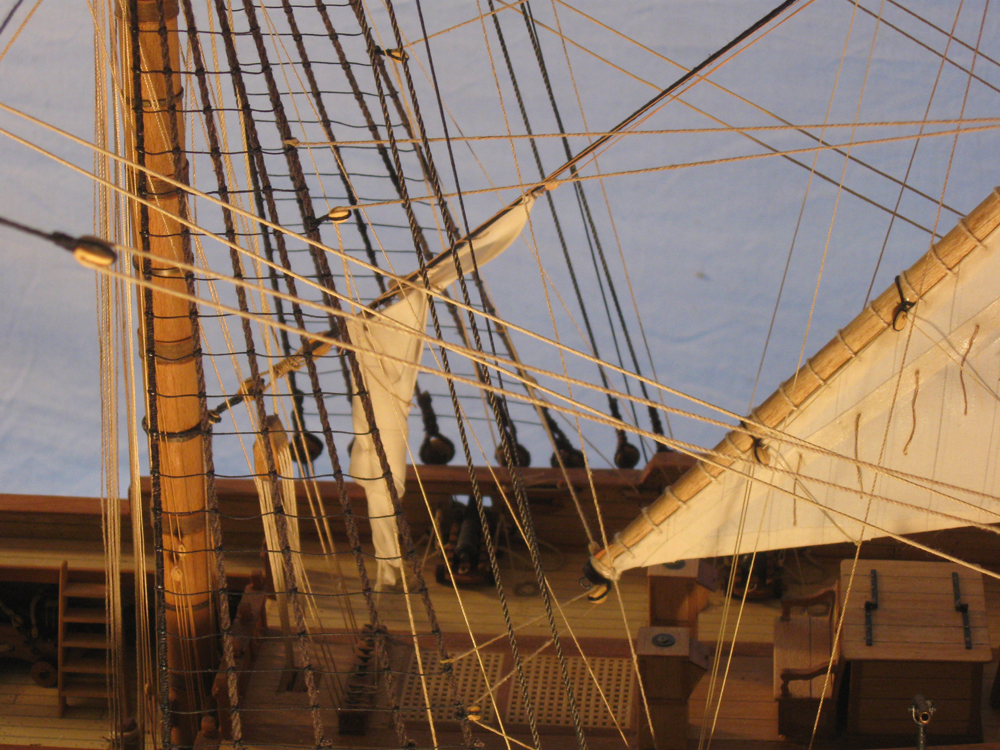
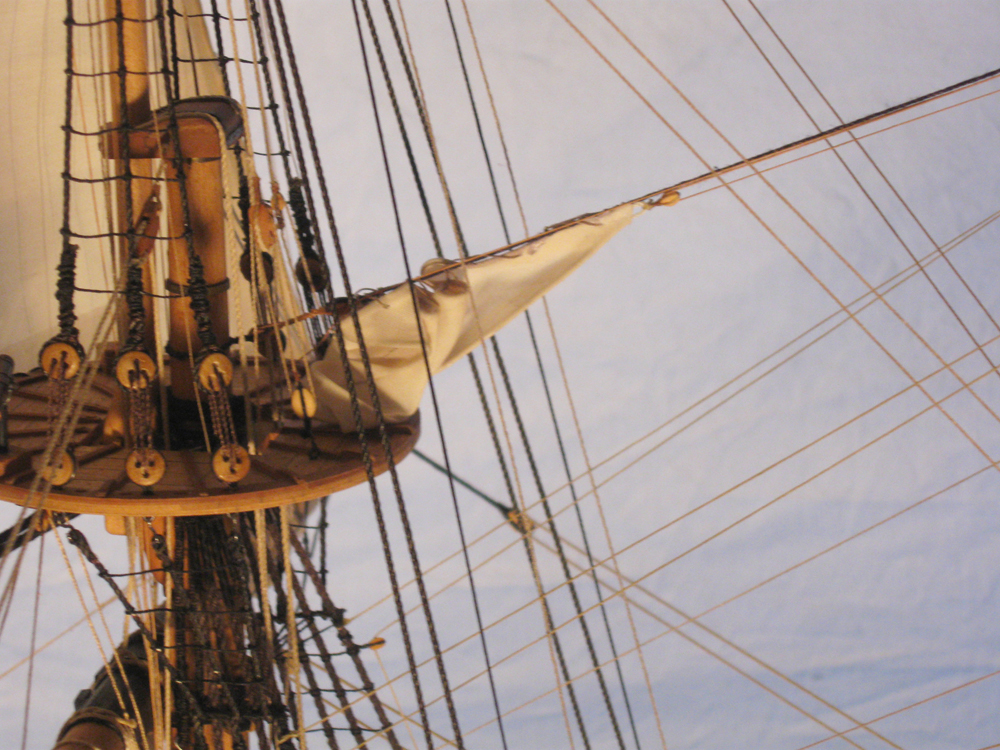
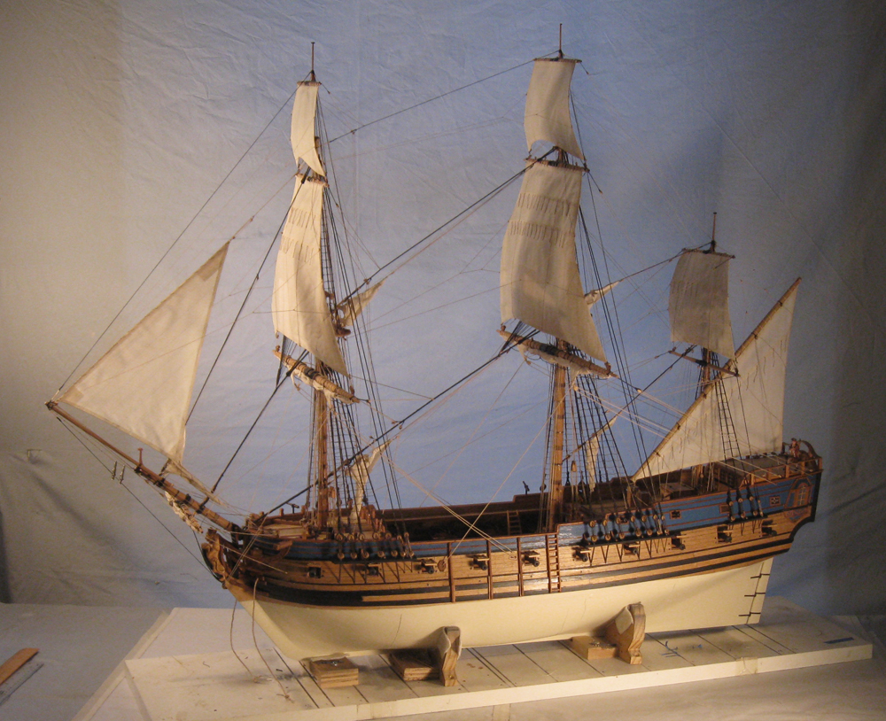
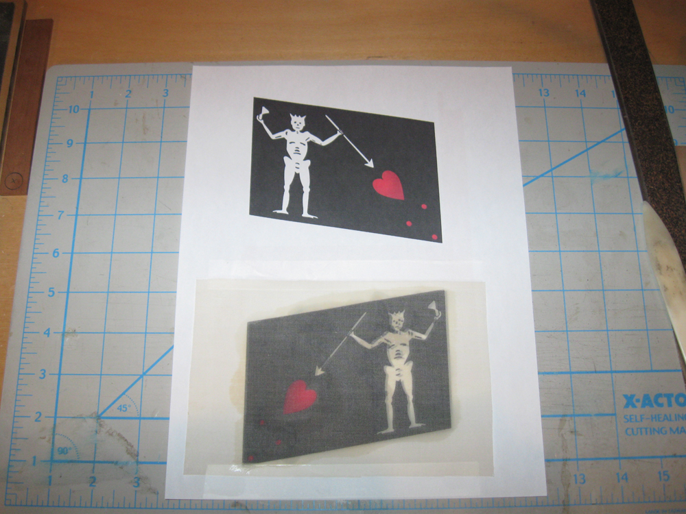
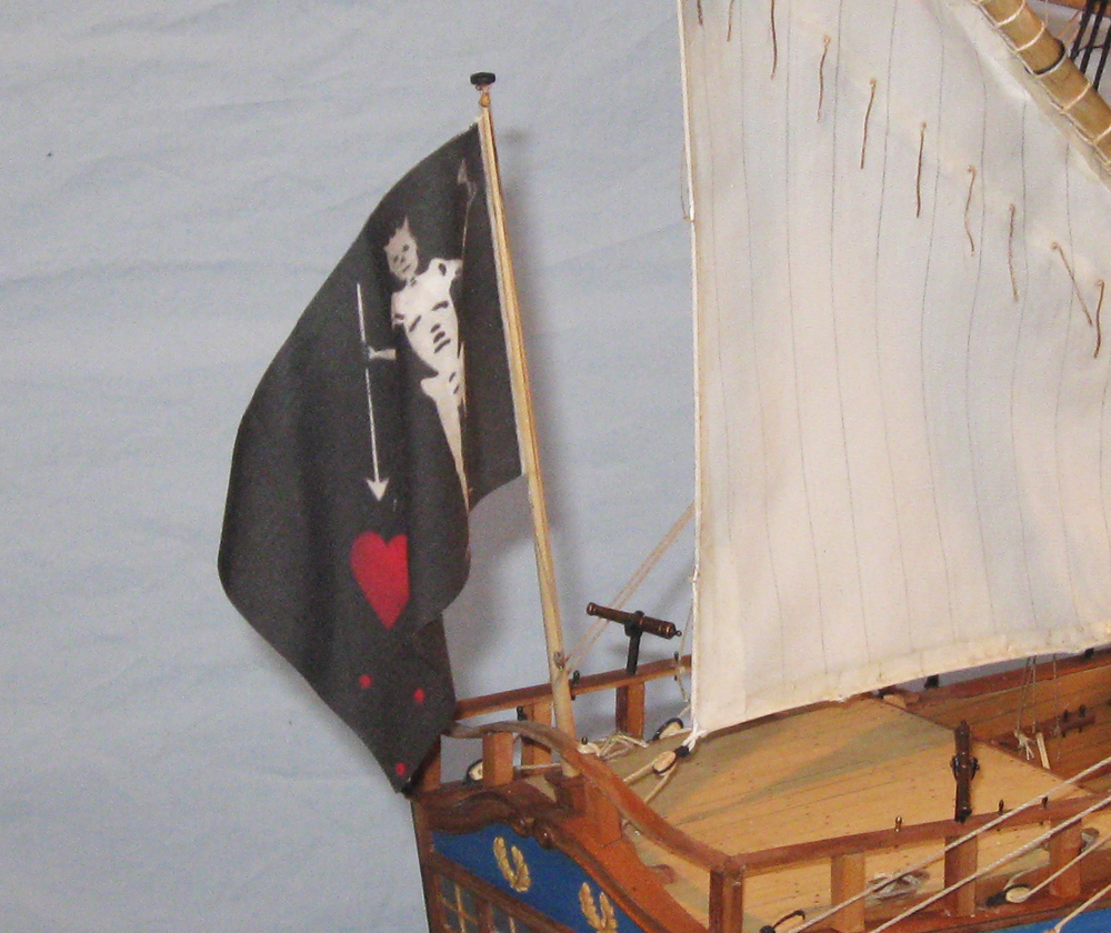
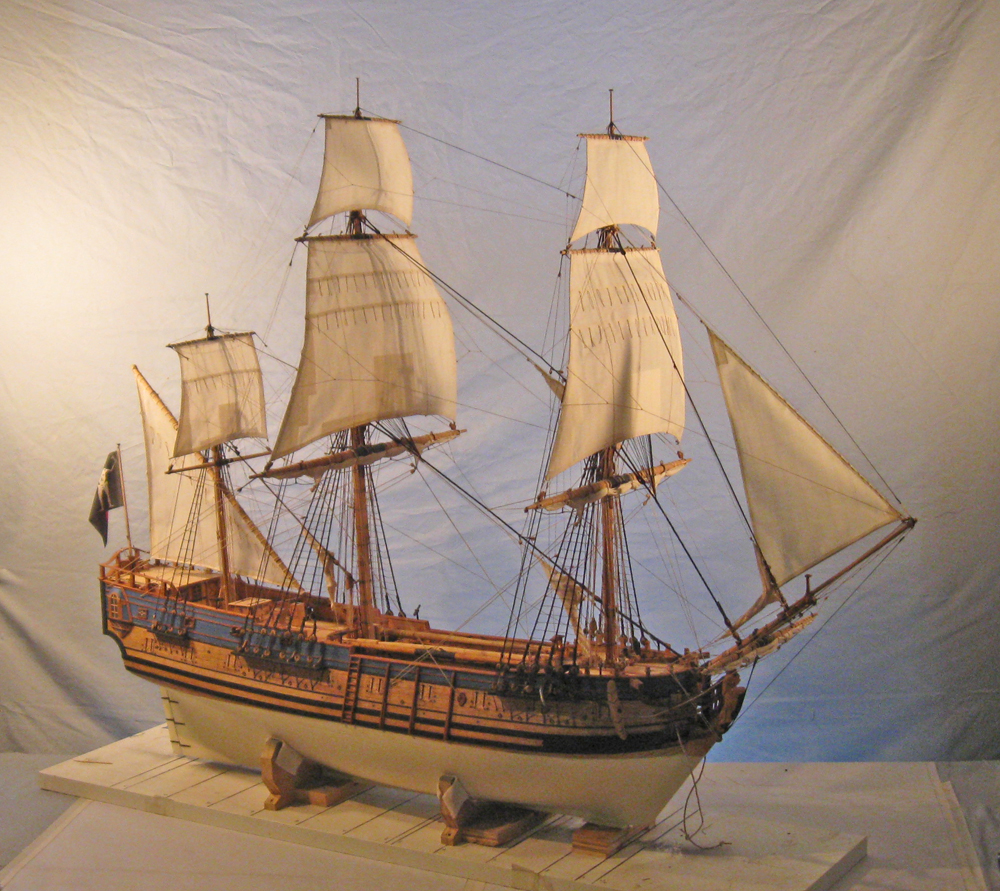
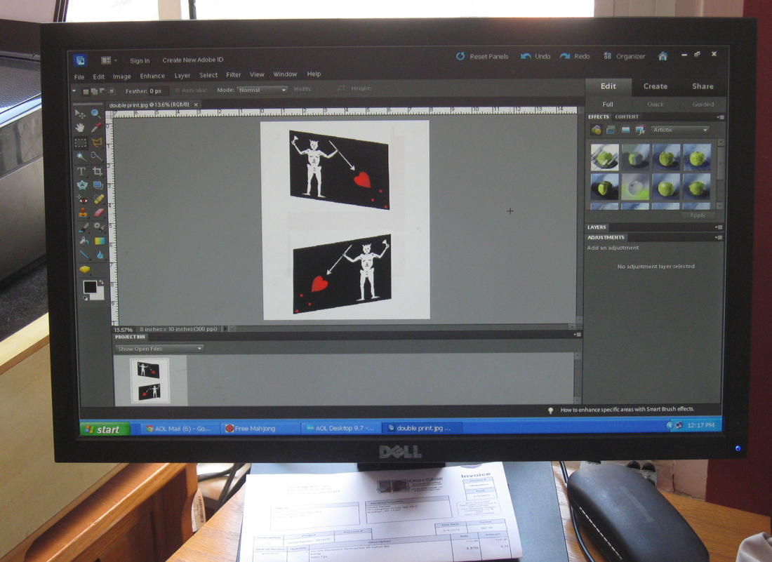
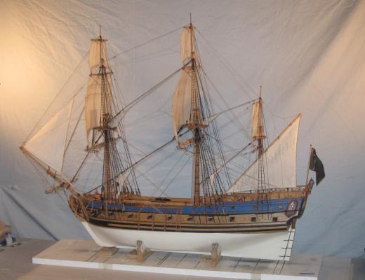
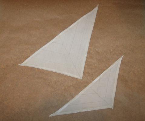
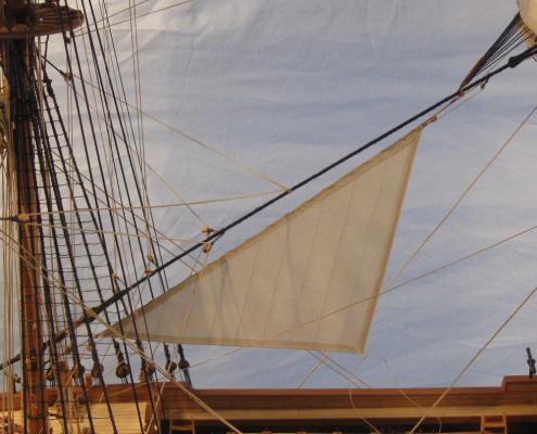
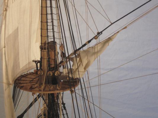
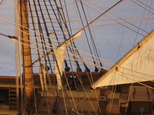
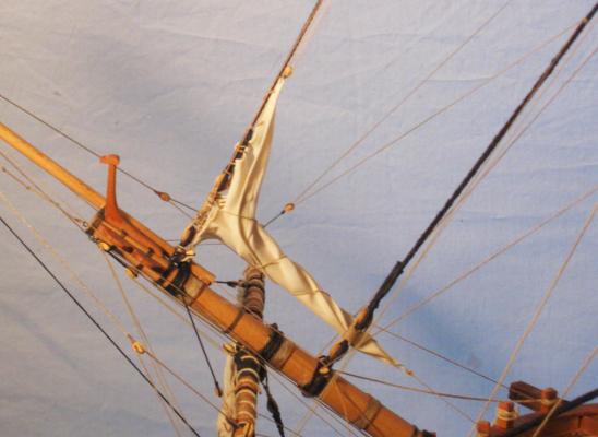
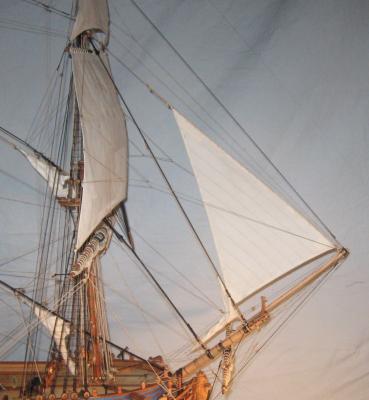
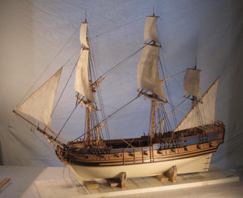
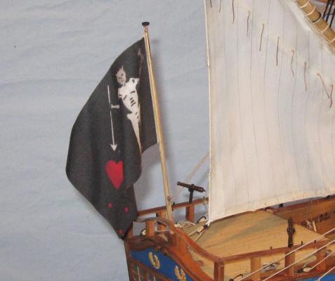
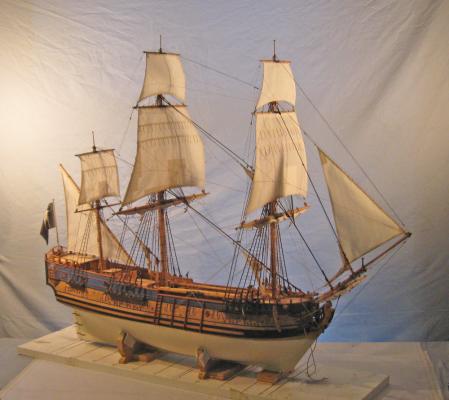
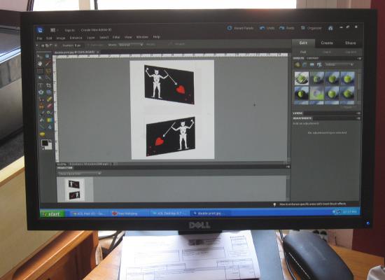
Hi all and thanks for the likes and comments. At the end of the last segment I had finished and hung the square sails. Now I turned to the staysails, most of which will be shown furled. The sails were made up much like the square sails, but as triangles rather than trapezoids. Here are the two from the first set that were made. They were discarded because the panel lines are wrong. The pattern with a central seam and angled panels is much more modern than would have been in use in 1710. I made a hasty assumption before checking my sources. 1 So here is the redone main staysail. It is reduced in size for purposes of furling, but is otherwise appropriately rigged. As explained by R.C. Anderson, the lines and blocks for the foreyard braces would have interfered with the staysail sliding up the stay. So a false stay was rigged under the mainstay and the sail is spiral laced to it. 2 The lower end of the false stay is secured to the foremast by a collar that rides just under the thumb cleat for the forestay (indicated by the arrow on the left). A small deadeye is turned into the collar and a matching one seized into the lower end of the false stay. The lanyard between them is tightened and the running end is frapped around it (see the arrow on the right). Lacing this in, around and through the previously rigged lines was one of the most delicate operations I have ever performed in my years of modeling. Suffice to say that I will pre-rig this next time. 3 The upper end of the false stay is comparatively easy. There is an eye splice turned into the end of the line, which is then seized to the mainstay just above the euphroe lashing. A single block is seized to the stay between the euphroe and the mouse to run the uphaul line for the staysail. 4 Once the sail was rigged, the lines were loosened, the sail misted with water and drawn down toward the foremast. It was furled, twisted, and wrapped with one leg of the sheet line, the other was used to secure the furled sail at the deck to one of the deck cleats. When I was happy with the look it was painted with matte finish to stiffen it. 5 Similarly, the main topmast staysail was rigged on its false stay. 6 The mizzen stays do not have any brace blocks rigged to them, so the staysails do not need a false stay. Here is the mizzen staysail. 7 And here is the mizzen topmast staysail. 8 The fore staysail was done in the same way. 8a The fore topmast staysail was set and shown billowed, its shape mirroring and complimenting the mizzen lateen sail. I first ran it down the t’gallant stay, but this did not seem right. First, it put it too far forward to look good to my eye. Maybe more important, rigging it that way would have one of the largest sails being run between one of the smallest diameter masts and the end of the jib boom, also not that large a timber. This is a broken masthead waiting to happen. Instead, I looked at some contemporary French models and usually saw a line running from the topmast head to the end of the jib boom. This looked much more likely, and gave the sail a nice angle and shape. 8b So here is the model with all sails set and rigged. 9 Next I turned to the flag. Although no one truly knows what his flag looked like, the Internet has one that is called the Blackbeard flag. It is a demon holding a glass in one hand and a spear in the other, aimed at a red heart with three red dots in the lower corner. This was the one selected by the museum. I took the image and imported it into my computer. Using Photoshop I resized it, then used the skew function to bring down the lower outer corner of the flag. This helps it to hang more naturally without a buildup of material. A copy was saved and reversed, then both were combined into one image. 10 The double image was printed out on a piece of paper. A piece of thin fabric large enough to cover the image with some excess all around was stiffened, then taped over the upper image and run through the printer. This put an image on the first side. The fabric was cut loose, turned over and positioned over the lower image. Since the fabric was somewhat transparent it was easy to locate it exactly over the previously printed image. Again it was taped down on all sides and printed again. 11 After allowing the ink to dry for 48 hours the flag was stiffened to lock in the ink, then cut out, leaving a bit of excess along the fly edge. The hauling line was set in and the flap glued over it and ironed down. The ensign staff was built up with a small block at the top and a cleat mounted at easy reaching height for a man. With the staff mounted the flag was misted and curled. 12 So here is the model almost done. 14 The next segment should be the last. Only the stern lantern to build and the anchors to mount. Back soon. Dan


- 241 replies
-
- 17
-
-
-
- queen annes revenge
- pirate
- (and 2 more)
-
Beautiful, smooth action, Michael. Sweet. Dan
-
Thanks to all for an interesting discussion. Dan
-
Jan - That's actually a good question, and not stupid at all. I recall reading contemporary accounts where such things did happen. However, I don't think that it would be a large problem here. The process of ramming the ball down onto the wad that covered the powder charge would tend to stick it together. Then, the ball and the inside of the barrel were pretty rough so there was a lot of friction, reducing the likelihood of it rolling out. If it was a problem, then a second wad rammed on top of the ball would solve the problem completely. If everything failed, it was only a one pound shot, about the size of a golf ball, so not much of a headache. This is my take on it based on only a few times when I watched or participated in firing reproduction black powder guns and small cannon. Anyone with more experience or knowledge is invited to correct me. Dan
- 241 replies
-
- 2
-
-
- queen annes revenge
- pirate
- (and 2 more)
-
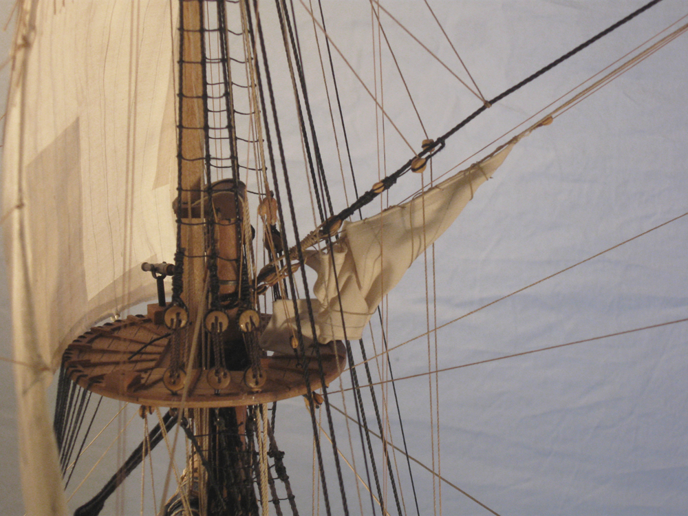
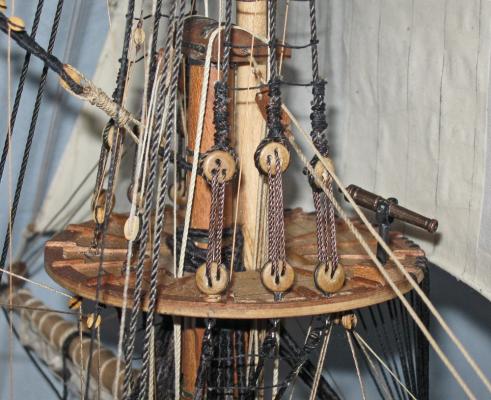
Hi all, and thanks for the likes and compliments. Matt - I don't have any definitive research or authority for my setup, but I mounted the swivel guns in the tops on blocks set toward the forward edge on both sides, giving them the best field of fire once the topsails are raised. However, only one of the blocks is used at any one time, on the theory that it would have been relatively simple to move the gun from one side to the other, and having two of them at once would be additional weight in the top that was not needed. That's my story and I'm sticking to it. Here is the foretop with the gun mounted on the starboard side. Hope that explains it. Dan
- 241 replies
-
- 10
-
-
- queen annes revenge
- pirate
- (and 2 more)