

LJP
-
Posts
132 -
Joined
-
Last visited
Content Type
Profiles
Forums
Gallery
Events
Posts posted by LJP
-
-
Hi Keith,
One of the best parts of the builds is how willing people are in sharing information. We all use ideas and methods that others have used and perfected. And for those of us less skilled ( a/k/a me), people are not judgmental, just helpful.
LJP
- Keith Black and Cathead
-
 2
2
-
Cathead,
Thanks but... the reason my build is where it is, is because of your builds. Among other things, I am not ready for the hull framing that you have done. And the detail on your machinery is exceptional. You are way too modest.
LJP
- Cathead and Keith Black
-
2
-
Keith,
Thanks! I struggled trying to make the air tanks until I stole these from my wife's craft projects.
LJP
-
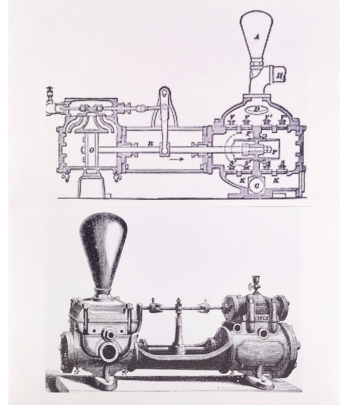
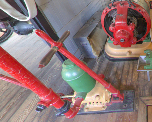
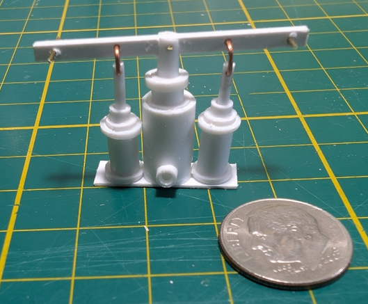
There are numerous examples of feed pumps out there. I did not use Moyie’s pumps as they are completely different and much more modern than many of the period single pumps. While I used photos of several different pumps for the period, the two following are the ones I most relied upon. My build used rocker arms (top photo) versus the older slide model on the bottom litho.
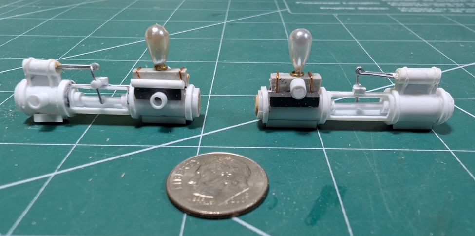
The dime is back! The finished but unpainted main and auxiliary pumps are below. I have included a photo of each side to show the detail. The air chambers are cut down corsage pins. The rest is numerous pieces of Evergreen plastic, wire, and thread.
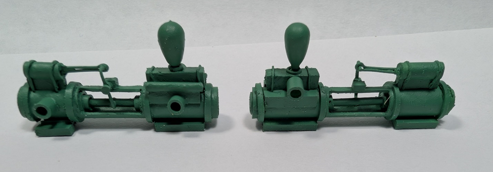
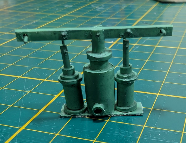
The finished products, again showing both sides. And “saved” with paint.
Now onto the engine assembly. This means I will need to build the engines, slides, pitman arms and the paddle wheel – along with the cylinder timbers and sternwheel bracing. This will take time and will be several individual projects.
I want to build each of the individual components and then place them where they should be in the final build. That way it will be easier to install during final assembly. Once completed, I can then build the crew quarters and layout the engine room before re-installing the engine assembly.
- Keith Black, Cathead, vossiewulf and 2 others
-
4
-
 1
1
-
Keith,
Great job!
But your "Valuable lessons learned should I have the opportunity to make another sternwheeler. " should read WHEN I make the next sternwheeler...
LJP
- MAGIC's Craig, Paul Le Wol, Canute and 2 others
-
4
-
 1
1
-
Thanks John,
I have lots of machinery to go. I am trying to provide more detail than when I did Thistle. I have learned a lot and hope to incorporate some of the changes as I go forward.
LJP
- Keith Black and Jim Lad
-
2
-
Keith,
Thanks again for both of your comments.
On a more serious note, take care. We do not bounce like we once did when we were younger. Hope to see more on your Lula.
LJP
- Cathead and Keith Black
-
1
-
1
-
John and Cathead,
Thanks again for your kind words. Suggestions are always appreciated as I am no expert by any means.
LJP
-
My major source for images of some of the machinery and the engine room is the S. S. Moyie (1898). Moyie is now a museum boat in Kaslo, British Columbia. It had an incredibly long life and ran Lake Kootenay until 1957. It has numerous YouTube videos, both of the ship as a museum, but also when it was still in operation. Several years ago, the museum website (which also has a Facebook account) had an interactive video (since discontinued, unfortunately) that afforded an true in-depth look at the boat. I have gotten screen shots from several of the videos.
Moyie had two manual pumps that I replicated. In the engine room was a manual fire pump while in the boiler room was a manual feed pump.
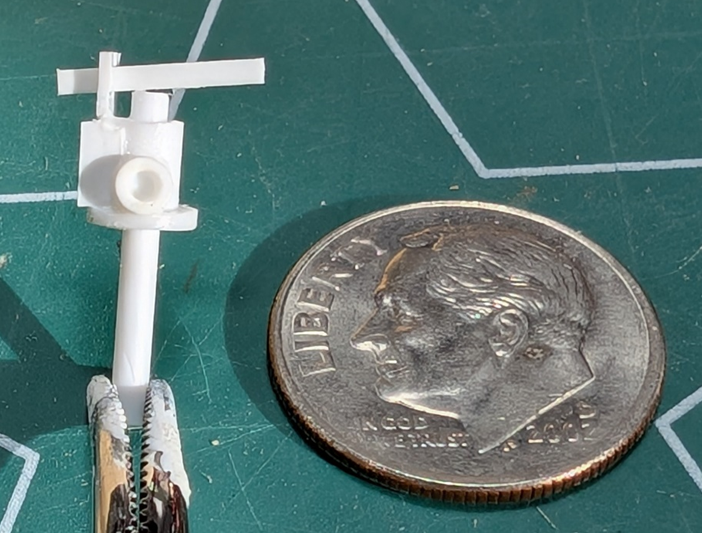
These are two photos of the fire pump.

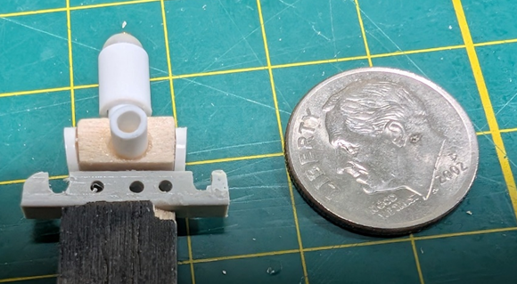
This is the build without the handles. Note a new dime – wore the other one out. The diameter of the dime equates to 3’ 8” in scale. I lightly glue small parts to scrap balsa to make it easier to airbrush or paint. That is what you see at the base of the part.
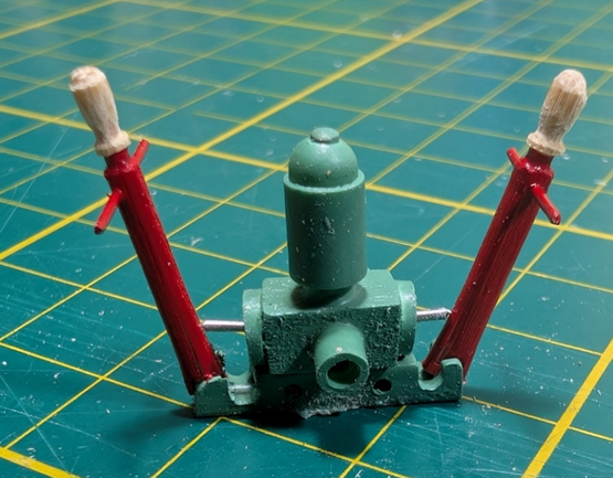
Finished product, with arms. Ready to be placed in the engine room.
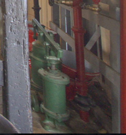
I do not have a great photo of the manual feed pump but it still provides enough detail for a build.
Another dime time before painting.
And the finished product. This will be placed on the main deck in front of the boiler pit, just like Moyie.
Next, onto the steam main and auxiliary feed pumps.
- vossiewulf, Cathead, Keith Black and 3 others
-
6
-
Hi John,
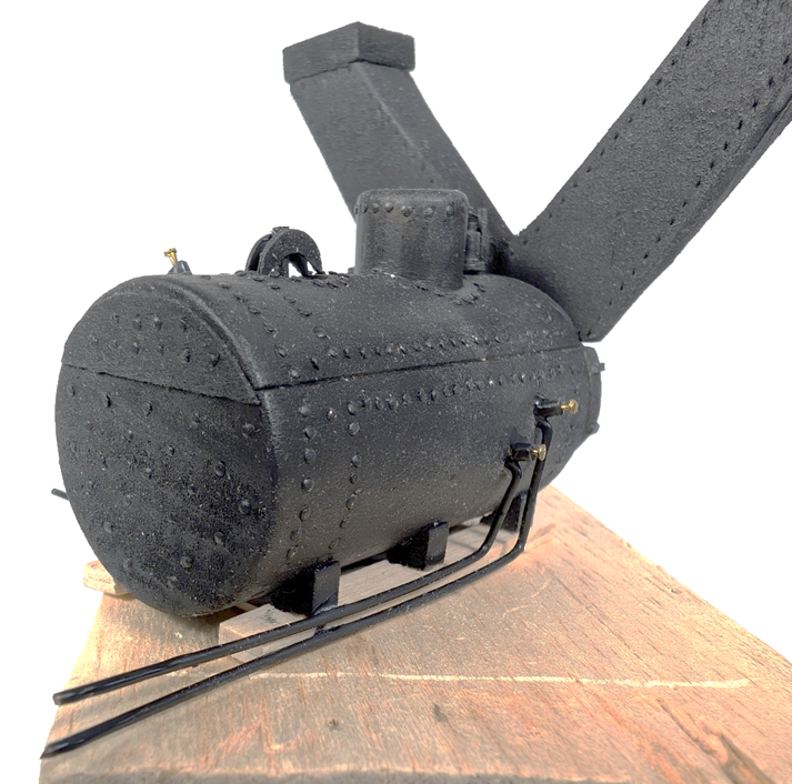
Here is the finished boiler assembly.
And John’s comment in Keith Black’s Lula build on painting saving the day is right on the money.
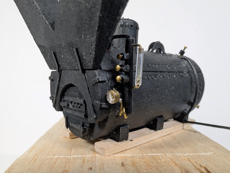
Here is my final painted ( a/k/a “saved”) boiler assembly. The actual boiler colour is a dark black. I enhanced some of the photos to show the detail as dark black obscures the detail..
This one is slightly enhanced. The gauges are on the right. The curved pipe on the rear of the boiler is the blow out pipe. The breechings are overly large due to photo perspective and have been cut off.
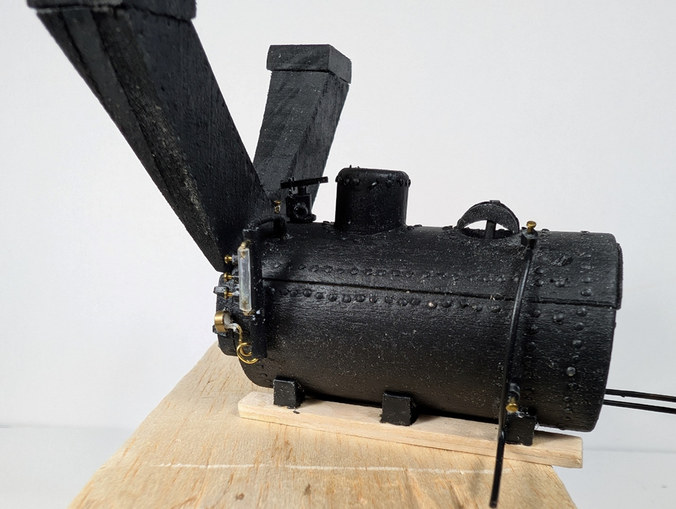
Side view, unenhanced. The safety valve and man hole cover are prominent. There is another view of the gauges and blow-outs.
Quartering rear view. This has been enhanced to show detail. This view shows the main and auxiliary water feeds.
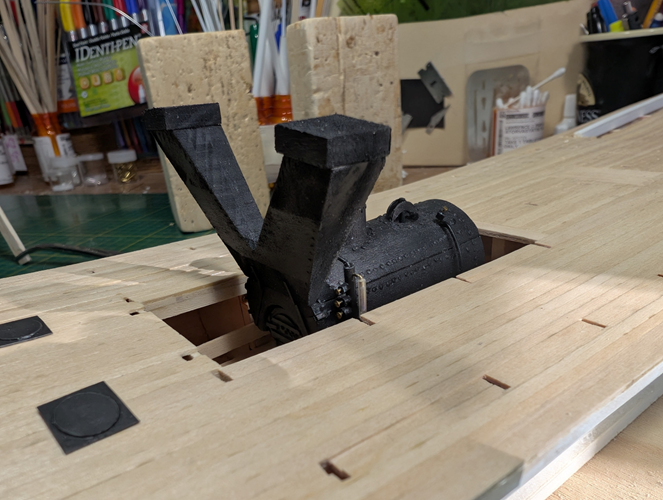
And here is how it looks in the hull. It has not been glued in yet as I do not want to damage it as I am working on other things. The black squares in the foreground are coal hatches.
Now onto the other machinery: engines, feed pumps, hand pumps & such. Still tiny stuff, probable re-dos and much more self-discussions. These are each little mini-projects so I will do a few at a time. I will start with the hand pumps.
-
Thanks Keith! Your Lula is still MUCH smaller and I have to hand to you on all of the detail.
And another thanks, as I have ordered the rivets from the link you provided. I hope to have these before I need to construct the pitman arms.
LJP
- mtaylor and Keith Black
-
2
-
I got to working on some of the tiny boiler assembly detail.
The door to the firebox was a challenge. I used plastic for the top layer and detail while there is a wood backing. The dime gives some sense of size.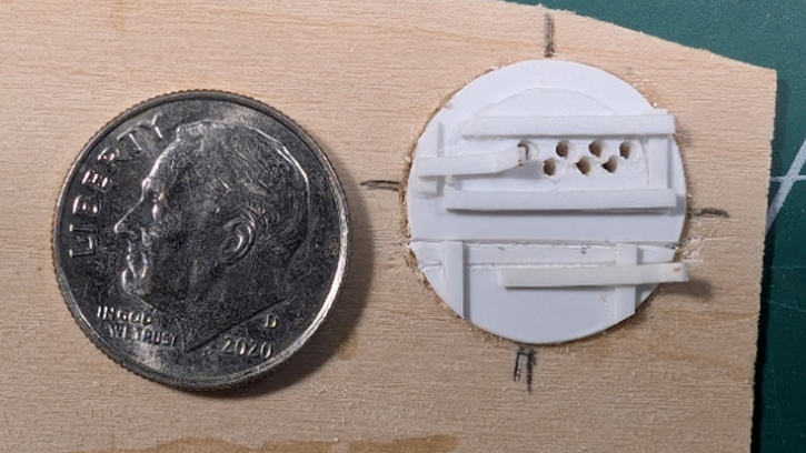
Another tiny addition was the safety valve. I used a safety valve litho from the International Library of Technology book from the 1890s. This was one of the books for engineers. It contains way more information (and mathematical formulas) then I ever want to attack. The part used six different type and size Evergreen plastics. Same dime, different boiler part.
An unusual construct on my boiler is the layout for the glass, stop cocks and water gauge. Marine Iron Works has a print from a photo (which means it actually was built) where all of the items were on a separate pipe apart for the boiler. I simply had to use this layout. As noted on Keith’s YouTube schematic, gauges &c. were often attached to the boiler itself.
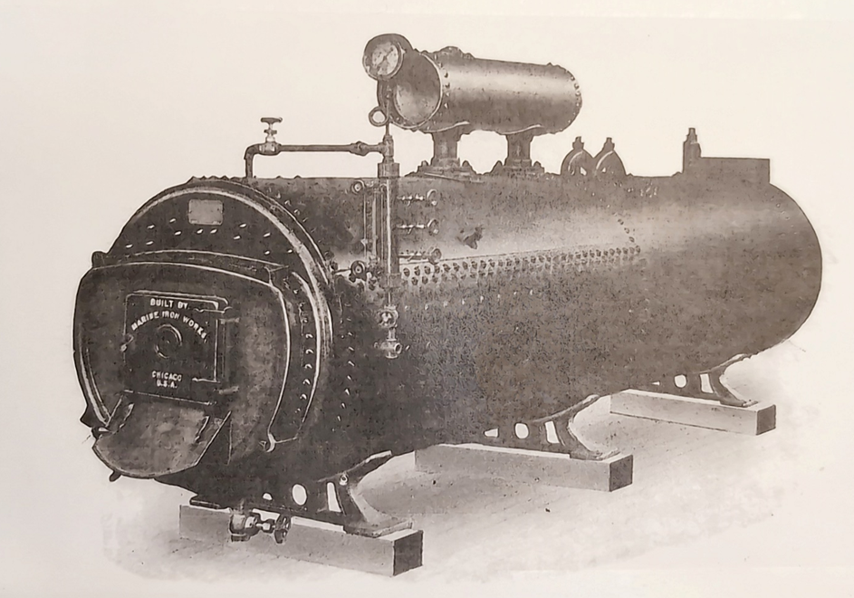 Source: Marine Iron Works of Chicago USA.
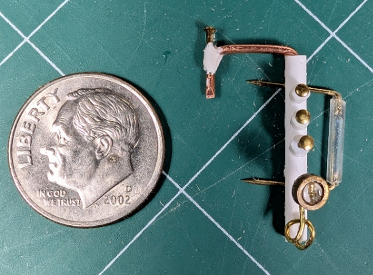
This is what I ended up with. This is a temporary layout that still needs to be painted, trimmed and then secured. I had to rearrange the components because of the dual stack breeching. This was a horrible build with redos and many conversations with myself. For the glass, I used a section of straight hobby bead . The gauge was a brass part from my possible box (everything possible is found in there). The pins will be trimmed after painting. Yup, same dime put to use again.
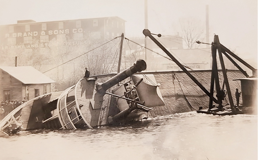
An issue I could not completely resolve was the breeching layout for dual stacks on the bolier. There were lots of single stack examples for a single Scotch Marine boiler, and numerous examples of multiple Western Marine boilers on dual stacks – but no dual stacks on a single boiler. I used a poor quality photo of the 1922 burnt Valley Queen (Ryan built ex- Leander Choate) from the Oskosh Public Museum for my layout. The breeching will seem huge in relation to the boiler. This may be due in part to the boiler being situated in a boiler pit within the hull as opposed to on the main deck. No dime, no photo.
The final boiler will also include the upper & lower blow-outs and main and auxiliary water feeds.
On to assembly and painting. This should not take too long.
-
Hi John,
Thanks for liking it. I have been spending time on the water glass/stop cocks/pressure gauge setup. This is taking me much more time than anticipated and a few re-dos. Some of the other details should go faster.
LJP
- Keith Black, Jim Lad, wefalck and 2 others
-
5
-
Keith,
Thanks for the info. I definitely would use this in the future. One of the issues using small nails is lack of quality control - heads misaligned, etc. Love your Lula, but the scale is beyond my abilities to do detailing like you have.
LJP
- Keith Black, Cathead and mtaylor
-
2
-
1
-
Building the boiler assembly turned into a project onto itself.
The J H Crawford had a single Scotch Marine boiler that had been built by Burns of Fort Howard (Green Bay) per period publications. The Milwaukee Public Library, Great Lakes Marine Collection, lists the boiler as a 6 foot diameter by 12 feet long Firebox boiler. At my 1/64 scale, this is 1 1/8 by 2 ¼ - which is large enough to include some simplified detail. The 12 foot length was noted on other Ryan built boats but diameters and number of boilers varied.
I used several sources to pattern the boiler. Like my Thistle build, I used Marine Iron Works of Chicago USA sales brochures and of course Bates. There are literally thousands of boiler photos in books and periodicals.
I also used Keith Black’s YouTube screen shots (below) of an actual 1887 Scotch Marine boiler which was immeasurably helpful. The screen shot of the actual boiler has been heavily enhanced to show the detail.
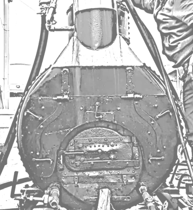
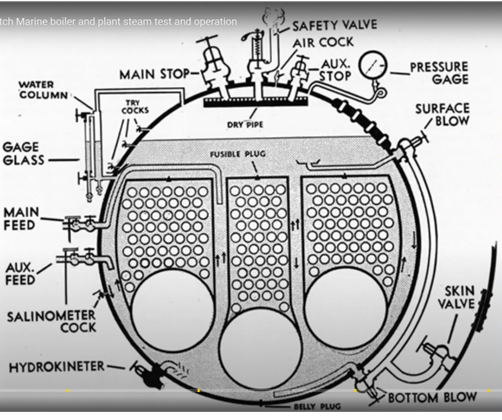
Source: YouTube Part 2:1887 Scotch Marine boiler and plant steam test and operation by A.E.Karnes
I started the boiler project by drawing simplified scale plans based upon my research. The face of the boiler looks a lot like the 1887 YouTube video while the boiler itself resembles the Marine Iron Works. These are the plans with an early start on the boiler.
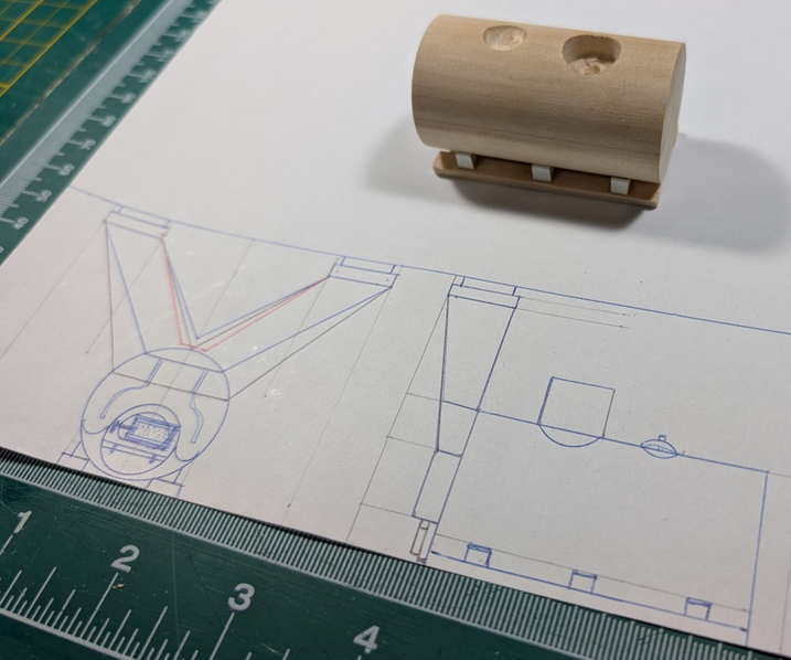
I simulated the boiler rivets using small nails. I used a ponce wheel for the spacing, but lots of drilling. I do like what the final result was even given the work to get there.
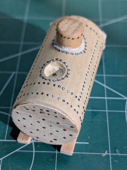
Next up, all the detail and painting.
- Keith Black, Cathead, vossiewulf and 4 others
-
7
-
druxey,
Welcome aboard! As I mentioned before, I am very good at missing builds. Glad to have you here.
LJP
-
Hi Cathead!
Glad to have you aboard also! I have really enjoyed your builds and have stolen many of your methods. And I will steal more of your ideas!
LJP
- Cathead and Keith Black
-
2
-
Hi John.
Welcome aboard! Trust me, you are not the only one who misses builds. I have been known to do so on occasion....
LJP
-
As promised, I finished planking the main deck.
Earlier I had mentioned that I was uncertain if the deck at the bow had a canvas or tarpaper cover. I recently obtained a clear photo postcard of the J H Crawford’s sister boat the Paul L. The Paul L capsized in May 1910 after being unloaded of coal on only the starboard side. It may be difficult to see here but the bow is clearly planked without canvas or tarpaper. Contrast that with the canvas used on the hurricane deck
This is my early process on planking. I added six access or storage hatches. I built those up on a maple veneer base and then placed them. All the planking was 1/32 by 1/8 basswood. The holes in the decking are where the mid-deck stationaries will be placed. The orange dot will place a capstan.
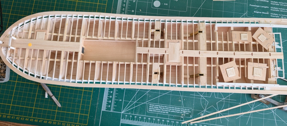
The finished product. I included numerous slots in the deck for the stationaries, hog chain braces and bits. This will be stronger than simply gluing them to the deck like I did on Thistle.
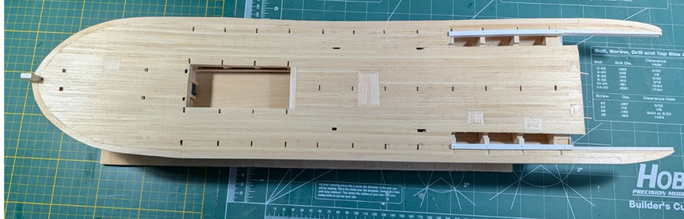
Next step is to begin building all of the “stuff” on the main deck. This includes machinery, engine room crew quarters, and of course, the Scotch Marine Boiler. Many thanks to Keith Black in his Lula build for finding a YouTube on an operating Scotch Marine boiler video. That will be a great help in building my boiler.
-
Merry Christmas (albeit a few days late...) and a Happy New Year to you Keith and your family. I really enjoyed your Pile Driver and am following your Lula build. I totally like unusual subjects. And your YouTube on a steam engine is absolutely unbelievable. Great find!
- Cathead and Keith Black
-
1
-
1
-
The video is incredible! Not only the detail on the boiler but the operating intricacies also. Great detail for your boiler!
- Keith Black, mtaylor and Canute
-
2
-
1
-
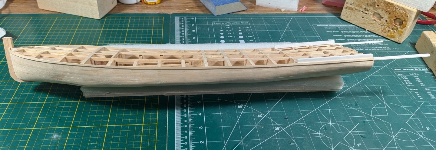
I ended up with another step before I can begin planking the deck.
As I mentioned earlier, I had problems with the hog chain braces getting in the way of later construction. So what I tried this time is epoxying 5/32 x 5/15 K&S brass tube as a guide in the hull. The 4/32 x 8/32 basswood hog chain braces are removable and just slide into the guides. It is hard to see from the photo, but the braces are all at 60 degrees. Hopefully, this will work better. I left the braces long and will cut down to length later.
I also added the rudders. I needed to add these now because of the decking over the false transom.
Lastly, I added the strake around the outside of the deck. I do not know what this is called – let me know if you know the correct name. On a clipper ship, the bow section is a nibbling strake – no idea what it is on a steamboat.
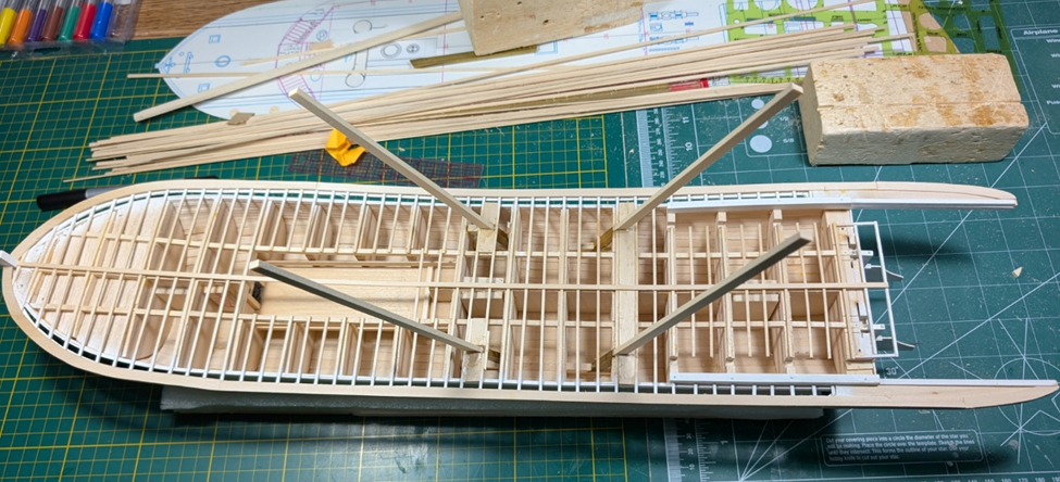
So now I finally can begin the planking. [ I promise I will do it this time] You can also see the center plank that I laid for a reference point. It will be trimmed for the boiler pit and hatches.
- KeithAug, Keith Black, Canute and 4 others
-
7
-
I decided to paint the entire hull white for want of a better decision. This is the hull colour of many of the museum steamboats. Likewise, this was probably the most economical as no tinting was required. So white it is.
I used Alan Bates’ method of combining the deck beams and the guard’s outriggers into a single beam. Much simpler and stronger. This is different from the Bertrand which had the outriggers separate from the deck beams. This is what my early gluing and clamping looked like. Lots of clamps…
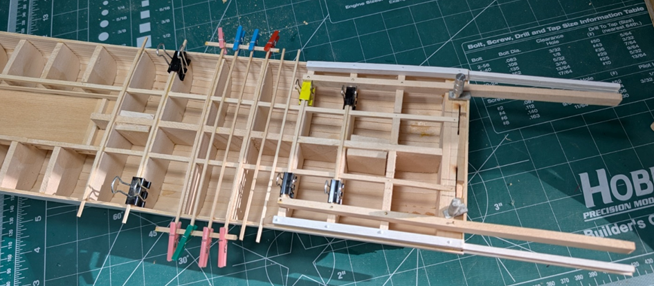
Another deviation was the outriggers at the stern where the wheel was located. Again, Bertrand had separate outriggers. However, JHC’s sister ship, the Paul L, had that area blocked in with timbers. This was evident with the Oshkosh Public Museum online photo of the Paul L when capsized. [I am not permitted to publish that photo here, but you can check their website.] So, I used solid blocking.
This is what the final product looks like.
My next project is to complete the main deck decking. There are a few issues there:
1. If the bow did not have a canvas or tarpaper cover, I would suspect the deck needed to be caulked. You would not want water draining into the hold where the coal bunkers are. Over the guards it makes no difference.
2. I may try something different for the hog chain braces. The braces really get in the way as you build the boiler deck and the staterooms. Maybe a guide in the hull where the braces can be removed during construction.
3. The same is true for the inner cylinder timbers with their support braces for the sternwheel. On Thistle, I completed them in situ – which was a horror story. Now I may make them a separate and removable component.
- wefalck, mtaylor, GrandpaPhil and 7 others
-
10
-
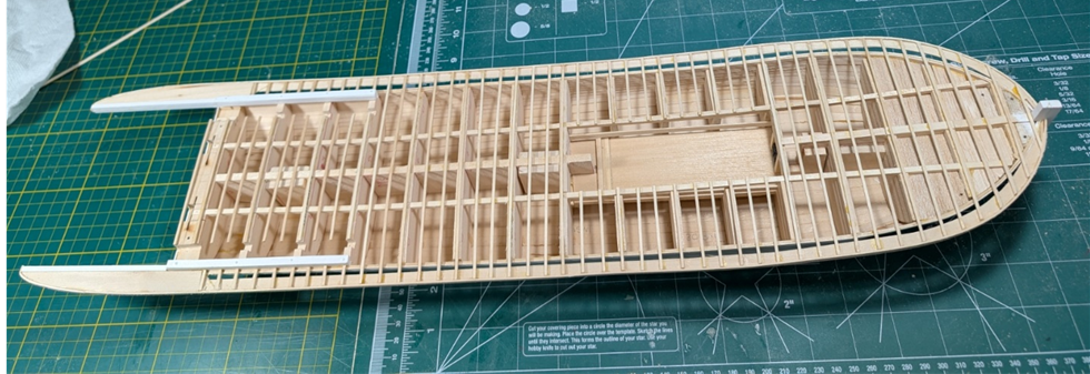
Well, its been a few months but my “other duties as assigned” are winding down. This has allowed me time to finally get the planking done. This has not been with out a few re-do’s on some of the individual planks but the product is now acceptable.
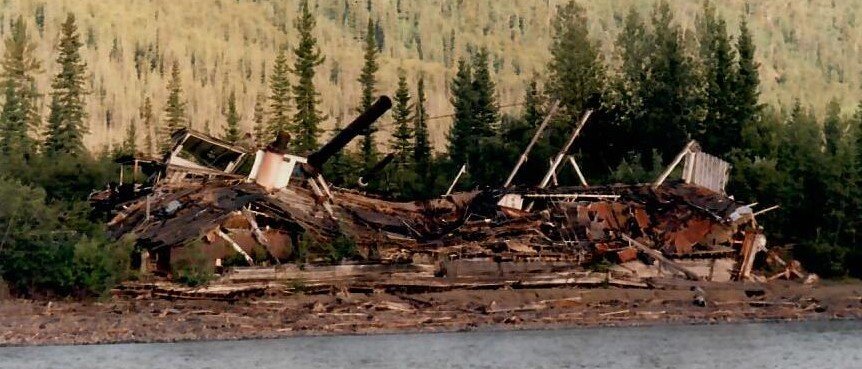
I now need to paint the hull. If you recall, Thistle was historically accurate with a green upper and “two coats of boiled linseed oil” below the waterline, circa 1908. I do not know what JHC’s colours were. For below the waterline, I have seen discussions for white, black and oxide red. Above the waterline, later Thistle photos seem to be white, black and grey. Or so it seems, given these were black and white photos or colourized. The JHC photo at the beginning of this article seems to be grey. I would appreciate if anyone has insight into hull colour schemes. Otherwise I will pick period appropriate colours.
Hopefully, my next entry will not take so much time as we head toward the holidays.
- KeithAug, Keith Black, Cathead and 6 others
-
9

Lula by Keith Black - FINISHED - 1:120 Scale - 1870s Sternwheeler Supply Boat for Floating Pile Driver
in - Build logs for subjects built 1851 - 1900
Posted
Keith,
Unbelievable detail at so small a scale! I know how difficult these engines are to build. Way to go!
LJP