


CPDDET
-
Posts
1,181 -
Joined
-
Last visited
Content Type
Profiles
Forums
Gallery
Events
Everything posted by CPDDET
-
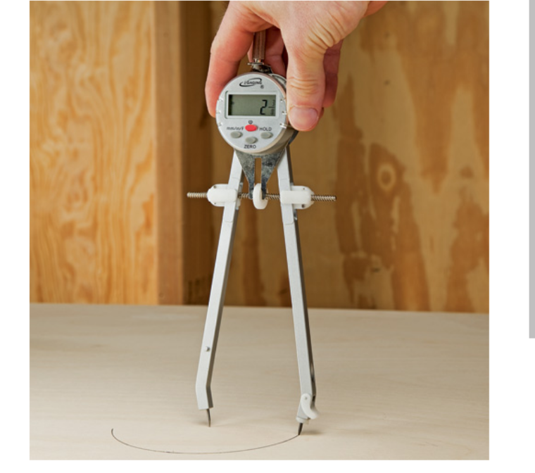
Anyone using this tool to make measurements on ships plans?
-
 Tough choice
 -
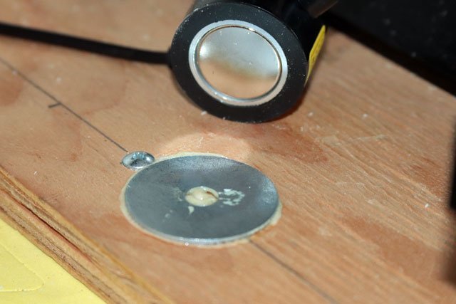
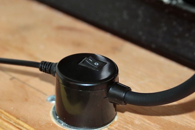
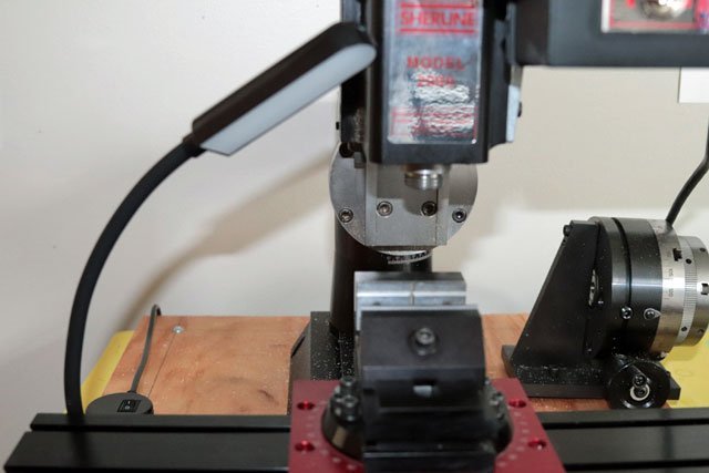
Paid $17 for this light on Amazon. It has a very strong magnetic base, but didnt come with a base plate. I picked up some 1.5 inch metal washers at the local Ace Hardware and glued one on on each side of the mill using Gorilla glue. This way I can switch sides or even purchase another light for cross lighting. Easy to reach on/off switch and plenty bright enough for my purpose. The 12 inch neck is perfect for a mill, saw, drill press, lathe etc.. But not long enough to use on the build table. A longer neck would be preferable for that.
-
My kit is the Bluenose, not the Bluenose II. Every photo I can find of the Bluenose shows a black bowsprit, so that's the way I'm going. And thanks for the compliment, mcb!
-
All the photos I have seen of the Bluenose II show the bowsprit painted black from the bow forward and white from the bow aft. My plans state the bowsprit is natural wood from the bow forward and white from the bow aft. Just wondering what others who are building the Bluenose have done. Dave
-
Boom tackles for late 19th c. fisherman
CPDDET replied to juhu's topic in Masting, rigging and sails
In my sailing days we called this a "preventer" as it prevented the boom from swinging across the deck if an accidental jibe occured. We always used one when sailing on a broad reach or down wind. -
Thanks for the tip!
-
I currently have a similar light on my work top but rarely if ever use the magnifier. Actually I need something much smaller and flexible for the mill. Currently researching magnetic LED lights with flexible goose neck. Sometimes called sewing machine lights. https://www.amazon.com/gp/product/B07J4ZKGF4/ref=ppx_yo_dt_b_asin_title_o00_s00?ie=UTF8&psc=1 I might even get 3 of these. I could then move them to different areas when needed (saw, mill, lathe) and also use them on the work bench for cross lighting. I would just use double stick tape for some large metal washers to mount them.
-
I have a Sherline mill and need a bit more light on my work piece as my 71 year old eyes could use the help. Has anyone come up with some kind of clamp on, screw on, glue on or other kind of small light to mount on their mill or other shop equipment? Dave
-
Going to have to print this out and put it in my notes binder. Thanks!
- 96 replies
-
- 1
-

-
- model shipways
- bluenose
- (and 1 more)
-
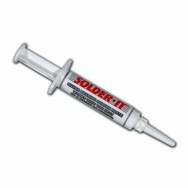
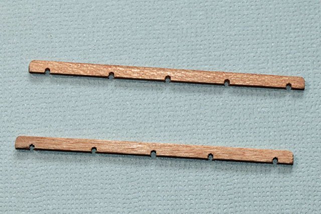
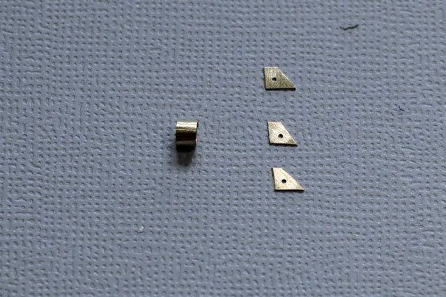
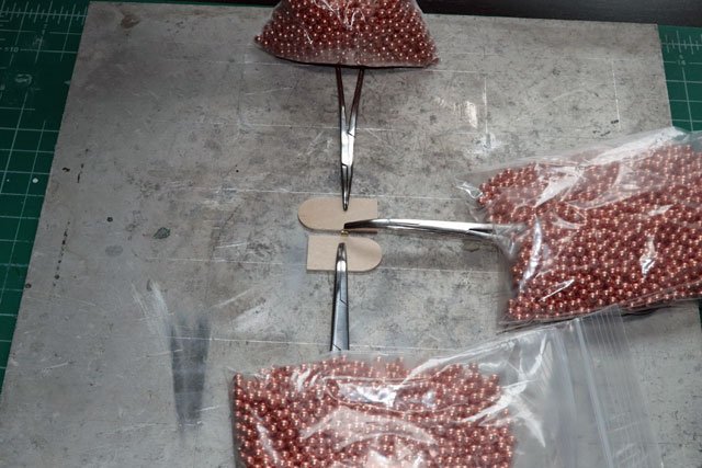
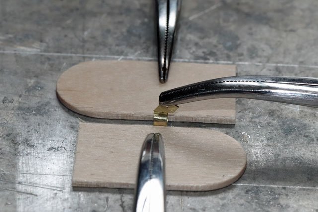
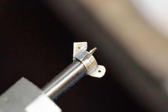
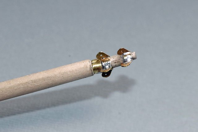
Started off making the battens for the jib stops. Had some scrap cherry so decided to use that. Then, after consulting with my usual mentors, made the bands and eyes. My plan shows the eyes slanting toward the ship so I cut the eye pieces at an angle to achieve this and drilled holes in them. This was the set up I used to solder the eyes to the bands. I found that using silver bearing solder paste worked great. It has a low flow temp, 450 degrees, and has flux mixed right in. I was able to place very small amounts where needed using a soldering pick. The brand I used was “Solder-It” but solder paste is much cheaper if purchased at a jewelers supply, like Rio Grande. The weights I used to hold the hemostats in place are just BB’s in small ziplock bags. I got 4 pounds of BB’s for 10 bucks on Amazon. Mounted the band on a drill bit shaft. Then mounted the drill bit on a hand vice and the hand vice on a bench vice. This gave me a sturdy mount to file the eyes into a rounded shape. Test fit before final cleaning and blackening
- 389 replies
-
- 4
-
-

-
- bluenose
- model shipways
- (and 1 more)
-
Welcome, Todd! Always nice to meet another modeler.
-
Welcome! I'm sure you will get all the help you need on this site.
-
Thanks again for your detailed info. It's going to be a big help as I proceed with the spars.
- 96 replies
-
- 1
-
-
- model shipways
- bluenose
- (and 1 more)
-
Wow! Looking very nice!
-
These highly detailed entries are going to be a huge help for me as I approach doing the spars. Thanks, Ed!
- 96 replies
-
- 1
-
-
- model shipways
- bluenose
- (and 1 more)
-
Yes, it's nice to have such a tool. But it's a huge learning curve for me. Having no experience at all with a mill, or lathe for that matter, has hampered my ability to use it to it's full advantage. These tools are great but having the knowledge on how to use them is the real key. No magic pill here.
- 389 replies
-
- 1
-
-
- bluenose
- model shipways
- (and 1 more)
-
Welcome Alex! Enjoy your new hobby.
-
Holy smokes!
-
Your ahead of me. At 71 years old my hands aren't steady enough for a carving knife.
-
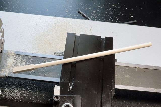
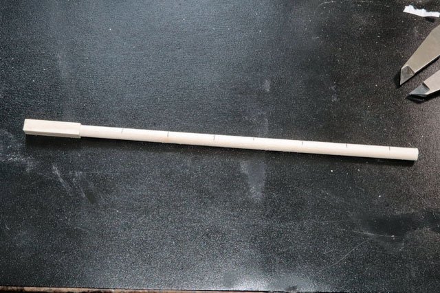
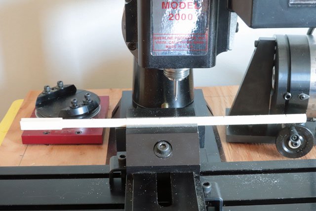
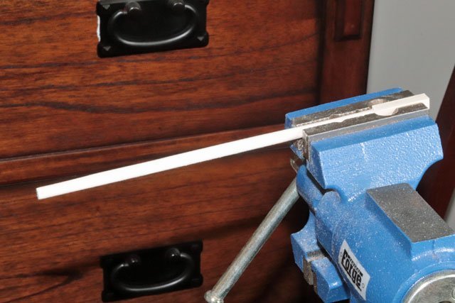
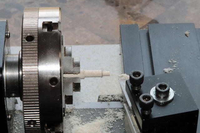
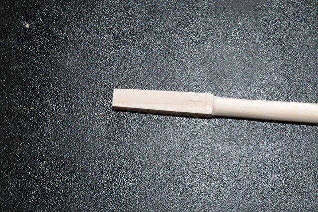
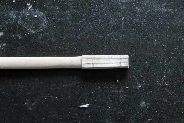
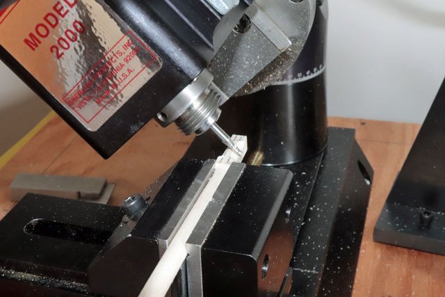
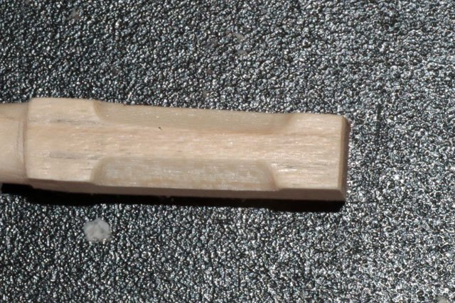
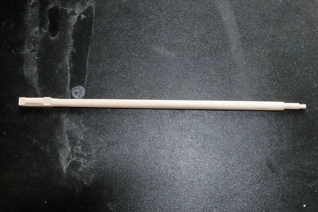
Thought I would post my building the bowsprit, even though it’s not totally finished. First off I would like to thank all of those who were kind enough to detail how they built this piece, including Suburban Ship Modeler, Ed KU20, Retired Guy and many others. Never could have done it without their documentation. I really wanted to build this part from scratch and decided to use poplar wood. It’s a step above basswood, cheap and readily available at big box stores like Lowes. But I fount still to be a bit too “fuzzy”, although it does give a bit better detail than basswood. Cherry would have been a better choice as it’s also readily available (at least where I live) not too expensive and allows much better detail than either poplar or basswood. When my skills progress further I will invest in more expensive wood types. While the plans call for the bowsprit to be painted white inboard and black outboard, I decided that I might want to stain the outboard portion and cherry wouldn’t have worked for that unless I wanted to do the masts in the same wood, which I didn’t. The poplar allowed me the option of either painting or staining the outboard portion. I started with a ¼ inch, square piece of poplar and turned it on the lathe Then, after taking several measurements, I marked the spar in locations for the taper at each end. Putting the spar on the mill, I cut grooves at the marked locations. The more the taper, the deeper the groove and vice versa. This would allow a guide when sanding to shape. I locked the spar in a vice and carefully sanded the top and sides to the proper shape, leaving the bottom of the spar a straight line (per the ships plans) Putting the spar back in the lathe, I cut the 2 stepped areas at the forward tip. After trimming the square area to the proper length, I tapered the sides I marked the square area for the chamfers Then put the piece back in the mill to cut the chamfers This is the finished square area. As you can see I didnt cut the tenon on the end as I didnt think far enough ahead and cut a mortise in the Samson post for it. But a test fit showed a nice snug fit between the deck and platform, and the tenon wouldn't show anyway. And this is the top view of the finished bowsprit All and all I was pretty happy with the shape, as it’s a bit tricky to get right with the bottom a straight line and the top kind of “humped”. Now it’s on to “dress” the bowsprit, which will put my metal working and soldering skills to the test.
- 389 replies
-
- 4
-
-
- bluenose
- model shipways
- (and 1 more)
-
1:54 HMB Endeavour
CPDDET replied to Tony_Brooks's topic in Building, Framing, Planking and plating a ships hull and deck
As you say, it's your model. So if your pleased with it that's all that really matters. I'm a firm believer in this approach. -
I'll second the use of fly tying line.
-
Nice way to "think outside the box", Richard. The scrolls came out beautiful!

