


CPDDET
-
Posts
1,194 -
Joined
-
Last visited
Content Type
Profiles
Forums
Gallery
Events
Everything posted by CPDDET
-
 Looks great and good technique!
 -
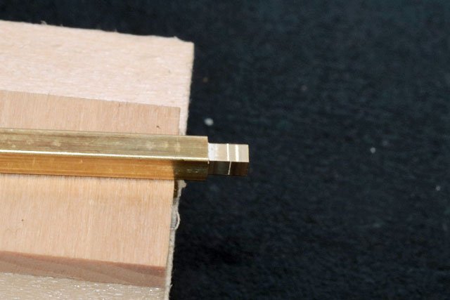
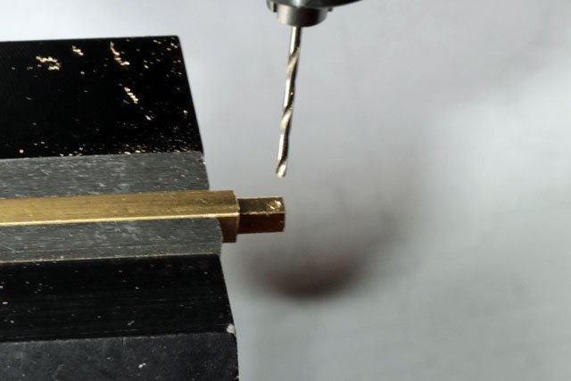
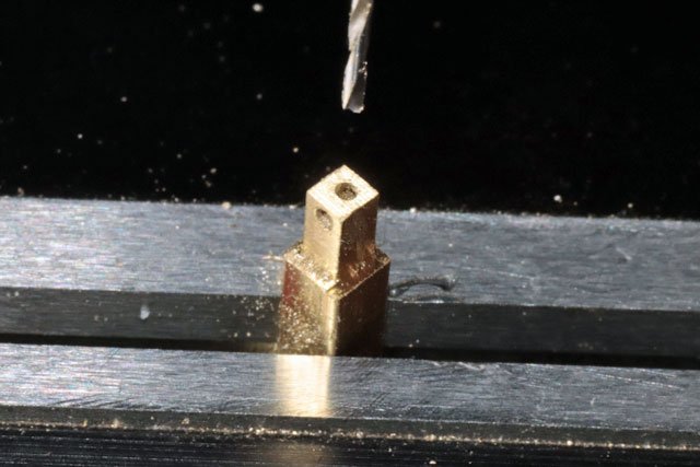
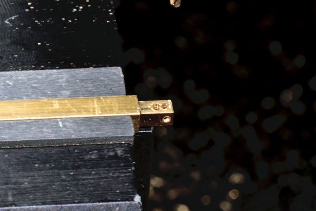
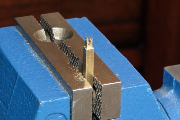
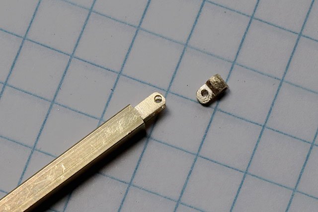
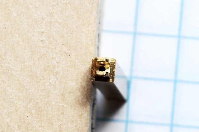
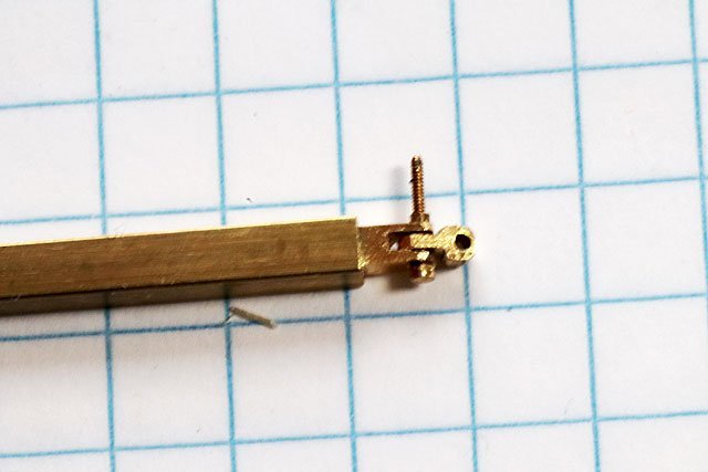
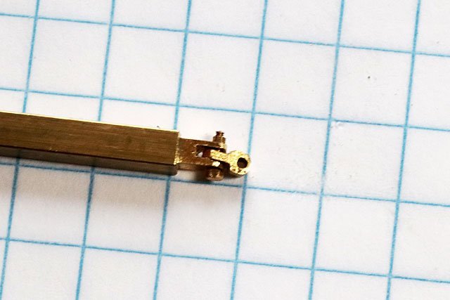
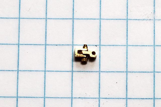
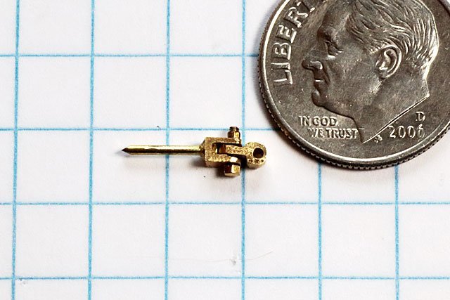
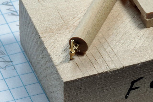
Finally got around to making the other half of the gooseneck for the foremast. Its been a while coming, LOL I began with a .125 square brass bar and milled it down to .085 Then used a #66 bit to drill a hole for the through bolt that would hold the two halves together Then drilled another hole into the face of the bar and two more holes into the side of the bar Then, using a file, joined the two holes to form a slot Checked the fit of the two halves Then drilled a hole straight down into the bar to accommodate a piece of brass rod that will be used to attach the gooseneck to the boom I attached the two halves with a .8 mm bolt and nut and trimmed off the excess Then used a jeweler’s saw to cut the gooseneck from the bar Used CA to glue the brass rod into the back side of the gooseneck This is a picture of the finished gooseneck mounted (simulated) on a brass rod with a piece of dowel for the boom. The boom can swivel port to starboard, slide up and down the brass rod and the gooseneck will allow the boom to lift after the downhaul is set
- 389 replies
-
- 4
-

-
- bluenose
- model shipways
- (and 1 more)
-
During my days of learning to sail through classes with the ASA, we learned to use a reef knot to secure the 2 ends of the reef lines. This is a common knot also known as a square knot. Easy to tie: right hand over left and then left hand over right.
-
Nice thinking outside the box! Dave
-
Welcome! Lots of great modelers here. Looking forward to seeing your builds Dave
-
Split ring making process
CPDDET replied to Dave_E's topic in Metal Work, Soldering and Metal Fittings
Always nice to get ideas/ advice from a master like yourself. Thanks! -
Welcome! While you will find a treasure trove of information here, we all will benefit from your experience as well. Dave
-
Split ring making process
CPDDET replied to Dave_E's topic in Metal Work, Soldering and Metal Fittings
They are very susceptible to side shock -
Split ring making process
CPDDET replied to Dave_E's topic in Metal Work, Soldering and Metal Fittings
And fairly inexpensive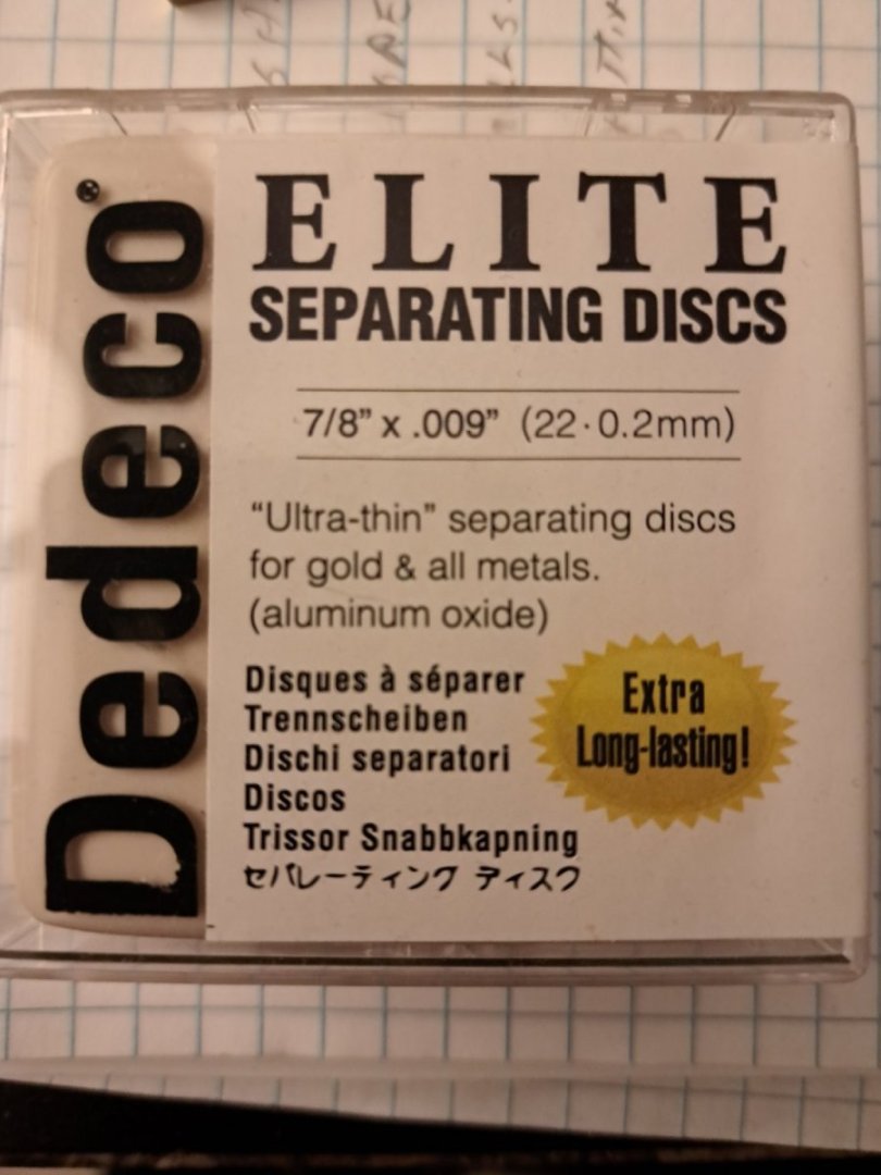
-
Split ring making process
CPDDET replied to Dave_E's topic in Metal Work, Soldering and Metal Fittings
My mind is still dwelling on this, crazy huh? Another cutting method might be a very thin cutoff disk in a dermal tool? I have some of these disks, very thin and quite fragile. But they cut beautifully. I'll check the name and post it. -
Split ring making process
CPDDET replied to Dave_E's topic in Metal Work, Soldering and Metal Fittings
After some thought it may help to dab a bit of CA on the dowel after wrapping the wire. This would aid in holding things while making the cut. Afterwards just drop the dowel and wire into acetone to dissolve the CA. -
Split ring making process
CPDDET replied to Dave_E's topic in Metal Work, Soldering and Metal Fittings
Hmm. Cutting with any kind of nippers will not provide a truly flat surface to butt against each other, if that's desirable. Never tried using a fine tooth jewelers saw or razor saw but that might work. But would have to make the cut while the wire is still wrapped around the dowel or drill bit shank. There would also be some loss of material (the kerf of the saw blade) causing you to end up with a smaller ID than desired. However, using a slightly larger dowel / drill bit shank could compensate for that. Perfection may not be attainable? -
Split ring making process
CPDDET replied to Dave_E's topic in Metal Work, Soldering and Metal Fittings
I find wrapping wire around the shank of a properly sized drill bit works best for me. The real challenge is keeping the diameter of the wire to scale. If the actual ring was made from 1/2 inch diameter, round, metal stock, then at scale the diameter would be 1/128 inch? Probably 36 - 40 gauge wire? -
Looking good!
-
Welcome to the group!
-
Bryan, welcome to this very rewarding and sometimes frustrating hobby. I'm sure you will find all the help you need here. Dave
-
Good evening from New Jersey USA!
CPDDET replied to Funkingonuts's topic in New member Introductions
Welcome, Mike! -
There are metal bars that protect the skylight glass. I was on Bluenose II a few years back and took a picture. Now if I could only find the photo.
-
There have been several different methods by different modelers for the windows / bars. Check out other build logs. I used straight pins for the bars. Some people used microscope glass slides for the windows.
-
Welcome Paul, good to have you aboard.
-
Welcome Tom, I'm sure you'll find help and some interesting build logs here. Dave
-
Nice, clean crafting on your first model. You look to be a natural! Dave
-
Welcome Mark, lots of help to be found here. Dave
-
Welcome home, sailor!

