


CPDDET
-
Posts
1,193 -
Joined
-
Last visited
Content Type
Profiles
Forums
Gallery
Events
Everything posted by CPDDET
-
 Looking good!
 -
Great idea on using the tape. Looking forward to seeing your progress on the spars. Not yet sure how to stain / varnish mine as I approach that step.
-
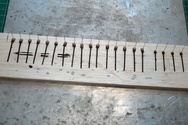
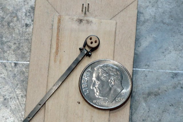
Took forever but all the chainplates are finished and ready to install. Now just have to work up the courage to mark the locations and start drilling the holes for them.
- 389 replies
-
- 4
-

-
- bluenose
- model shipways
- (and 1 more)
-
You can use a piece of tape with the size written on it around 1 piece and band them together with a rubber band.
-
Not sure exactly what you need help with here. Separating by size could be as easy as measuring the width and thickness of the "sticks" / planks? Perhaps you meant something else?
-
Looking for a good "starter" pin vise set
CPDDET replied to Capella's topic in Modeling tools and Workshop Equipment
You will often hear most people on this site say, "Buy the best tools you can afford". And I agree. If this is going to be a long time hobby for you, I can recommend a pin vice set by Starrett. Not cheap but very well made and sould last you a lifetime. -
The kudos are well deserved
-
Excellent scratch build, Pat
-
They look great against the copper plate. I've often struggled over consistency in my model when it comes to metal work. All blackened? All natural brass color? Mixed?
-
Just a thought. Did you consider blackening these pieces or coating the brass to prevent discoloration?
-
Crisp, clean and nicely detailed. Very nice work, Pat.
-
Thanks Pat, slow going but forging ahead.
-
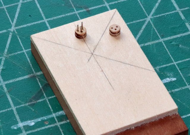
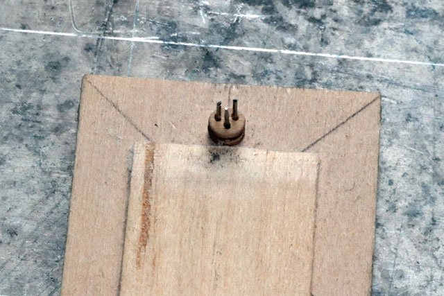
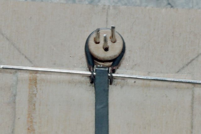
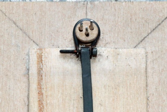
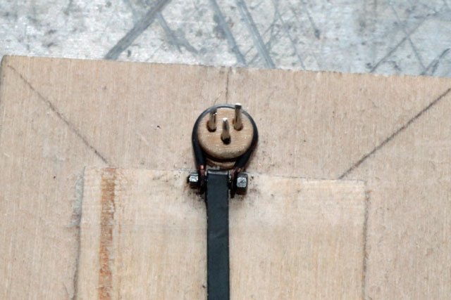
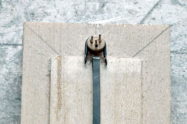
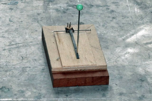
In order to assemble the chainplates, deadeyes and deadeye strops I needed a way to hold everything in alignment. So time to build a jig. Using one of the deadeyes as a template, I marked the 3 holes and drilled through the wood base. Since these holes needed to be as straight as possible, I did them on the mill rather than free hand (a drill press would work nicely as well). Then ran 3 straight pins through the wood base from the bottom with a touch of CA and clipped off the excess length of the straight pins. This allowed me to drop each deadeye over the pins and hold it in place. To help keep the deadeye, strop and chainplate in alignment, I added a piece of scrap wood and sanded it down to ½ the thickness of the deadeye. After placing a deadeye on the pins, I added the strop and laid in one of the chainplates Used a straight pin to further align the pieces Then used a pushpin through one of the predrilled holes in the chainplate to help hold that steady. Then it was just a matter of removing the straight pin and replacing it with a .8mm bolt Threaded on the nut and trimmed off the end of the bolt One down and 19 to go!
- 389 replies
-
- 5
-
-

-
- bluenose
- model shipways
- (and 1 more)
-
That will be the best beer I've had in 2 years! LOL
-
As always Pat, your setting the bar for the rest of us.
-
First or last, your doing an excellent job! I'm already rethinking my next build, so I can see where you're coming from.
-
Looking really good. Don't know if I'll ever copper plate a hull. But if I do I'll follow your excellent work. Keep up the great work, you've got a stunning model going.
-
I should add that I used 20 gauge solid copper wire for the strops. I found copper much easier to work with than brass wire; softer, easily shaped and less "springy" that brass. From what I can find out, there should be no reaction between the 2 metals (brass & copper) being in contact with each other.
- 389 replies
-
- 2
-
-
- bluenose
- model shipways
- (and 1 more)
-
Im pretty sure the coats of wipe on poly made a smooth, non porous surface for the tape. Great job!
-
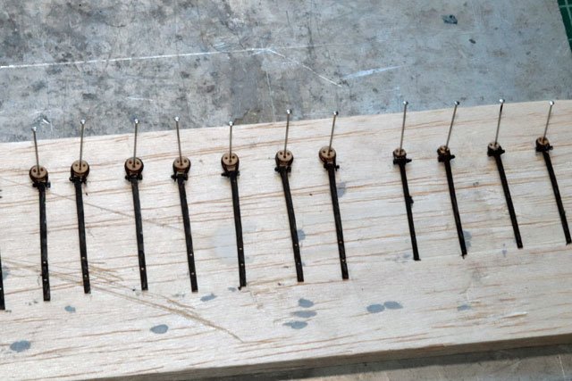
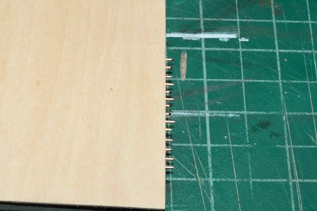
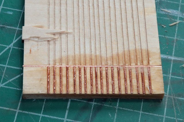
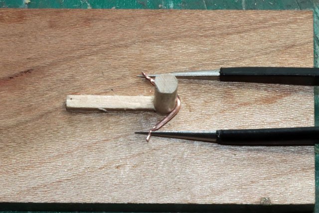
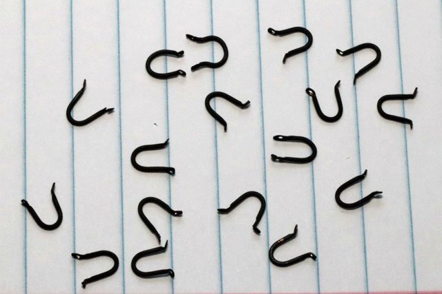
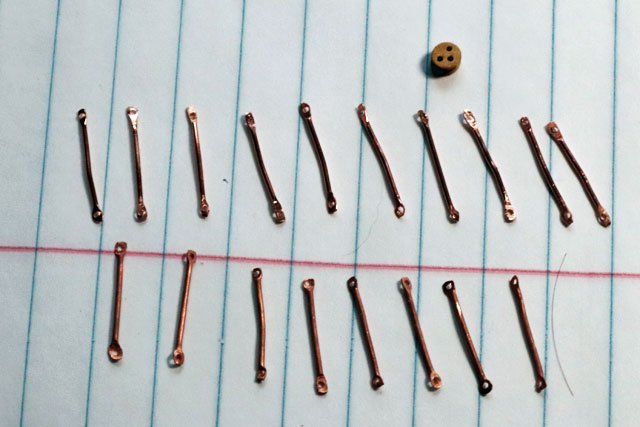
Things slowed over the past 3 weeks. Was down with a sinus infection for a 10 days, then came holiday decorating and finally the family Christmas celebrations. But eventually I got back to the build. After measuring the proper length of the strop needed to get around the deadeye, I grooved a scrap piece of wood on the Byrnes saw to hold the individual strops. To keep things as accurate as possible I cross grooved the scrap piece wood and glued in a piece of wire to butt the individual strops against. I rough cut the strops laid them in the jig and glued them in place with CA. Then added a thin piece of wood on top so the strops were sandwiched between the two pieces if wood. Then trimmed the exposed end of the strops. After soaking the jig with acetone, I removed the strops and cleaned them up in an acetone bath and a soft sponge sanding block. Using a pin driver, I flattened the ends of each strop and drilled holes to accommodate the bolts I will be using. Threw together a jig using a dowel rod of the same diameter as the deadeyes. The horizontal piece of wood butted up against the dowel was used to simulate the width of the chainplates. Using a very thinly pointed pair of tweezers inserted in the end holes, I was able to shape the strops around the dowel. Then got them cleaned and blackened. Still must blacken the bolts and nuts and then begin the assembly process.
- 389 replies
-
- 6
-
-
- bluenose
- model shipways
- (and 1 more)
-
Really beautiful work, Pat. Slow and steady wins the race, you're proving that.
-
Nice work Pat, thanks for sharing your process.
-
Looks darn good to me!
-
Very nice 👍
