HOLIDAY DONATION DRIVE - SUPPORT MSW - DO YOUR PART TO KEEP THIS GREAT FORUM GOING! (89 donations so far out of 49,000 members - C'mon guys!)
×


Dr PR
-
Posts
2,446 -
Joined
-
Last visited
Content Type
Profiles
Forums
Gallery
Events
Everything posted by Dr PR
-
 Interesting question. I have heard that also, but have never seen a reference. I have always thought that the foot of the mast rested in a fixed mast step, so that end couldn't move without removing the mast and rebuilding the step. There is some space around the mast at the "partners" - where the mast passes through the main deck. This space is filled with wedges to fix the mast in place. I suppose by using thick and thin wedges properly spaced around the opening the angle of the mast could be varied a bit, both fore and aft (rake) and side to side. I can see where this might change the angle of the rake by a degree or two. Again, I think this would have to be done in port. All of the stays and shrouds would have to be loosened and adjusted, and you wouldn't want that to happen at sea!
 -
Another publication I have found useful is George Campbell's The Neophyte Shipmodeller's Jackstay, Model Shipways Co., Inc., Bogota New Jersey, 1962. This 60 page booklet was intended to be an introduction to ship modelling for beginners. It doesn't describe any vessel in particular, but has a lot of bits of information about things found on sailing ships with many illustrations. I have found it useful as an illustrated "dictionary" for nautical terms.
-
Mark, Here is a list of the most useful books I have found for topsail schooners. Some time back I posted this list in the topsail schooner rigging article: https://modelshipworld.com/topic/25679-topsail-schooner-sail-plans-and-rigging/?do=findComment&comment=750865 1. To me the most important reference is Howard Chapelle's The Baltimore Clipper (Edward M. Sweetman Co., New York, USA, 1968). It has a lot of information about the development of topsail schooners and lots of drawings and illustrations. More importantly, it lists the dimensions of actual vessels in the early 1800s. It has many sail plan drawings, but says little about the rigging. 2. The Global Schooner by Karl Heinz Marquardt, Naval Institute Press, Annapolis, Maryland, USA, published by Conway Maritime Press, London, 2003. This book is devoted to the history and construction of schooners. It has an exhaustive history of the schooner rig - the best I have seen. The book has very detailed chapters on masts and rigging with detailed drawings. Numerous tables in the appendices give rules and dimensions for mast, spars and rigging. It is the most complete text on schooner rigging that I have found. It is a large book (11.6 x 10 inches, 294 x 254 mm) with 239 pages containing many detailed drawings, full page ship plans and illustrations. 3. Lennarth Peterson's Rigging Fore-and-Aft Craft (Naval Institute Press, Annapolis, Maryland, USA, 2015) has a section on topsail schooners, and most of this also applies to straight fore-and-aft schooners. He has drawings showing just about every possible line you could have on a schooner. 4. Howard Chapelle's The American Fishing Schooners 1825-1935 (W. W. Norton & Company, New York and London, 1973, 690 pages) is a must if you are interested in these schooners. It gives the history of these ships. However, it has a 371 page "Notebook" with very detailed drawings and descriptions of just about every part of schooner structure and rigging, and much of it applies to all schooners. 5. John Leather's The Gaff Rig Handbook (Wooden Boat Books, Brooklyn, Maine, USA, 2001) gives a lot of detail for rigging modern fore-and-aft yachts and racing boats, but much of this isn't very useful for 19th century and earlier vessels. However, he does give the history of the development of different types of rigs, mainly focusing on British vessels. But the book doesn't have a useful index and finding information about a particular rigging detail is like looking for a needle in a haystack. 6. Harold Underhill's Sailing Ship Rigs and Rigging (Brown, Son & Ferguson, Glasgow, Scotland, 1969) has general sail plans for many types of ships and boats but not much about the actual rigging. But it does have a useful glossary. 7. An excellent reference for the development of fast sailing ships is Howard Chapelle's The Search for Speed Under Sail (W. W. Norton & Company, New York, USA, and London, Great Britain, 1967). It has some sail plans for schooners and a few rigging diagrams. 8. I also have Underhill's Masting and Rigging the Clipper Ship and Oceanic Carrier (Brown, Son & Ferguson, Glasgow, Scotland, 1972). It is an excellent book with a tremendous amount of detail about sails and rigging. It is mostly for British clipper ships, but it has a section on schooners. Unfortunately the drawings seem to be scattered randomly through the book and are rarely anywhere near the text that refers to them. But it does have a list of drawings after the table of contents. Most of what he writes about are rigs of the last half of the 19th century and early 20th century. If you are interested in clipper ships this is a must have! It has perhaps the best and most inclusive index of any book I have seen, with links to descriptions of every part of the ship. 9. James Lees' The Masting and Rigging of English Ships of War 1625 - 1860 (Naval Institute Press, Annapolis, Maryland, USA, 1990) is almost entirely about larger square riggers. However it does give a lot of detail about parts of rigging that does apply to schooners. More importantly, it tells how to determine the dimensions of spars, rigging, blocks and such based upon the mast diameter, and has lots of tables. But some caution is necessary because fore-and-aft rigs are much lighter than square rigs, and mast diameters are usually smaller for schooners. And the text can be confusing because he often fails to explain exactly what dimensions he is referring to. Mast and spar dimensions are usually diameters but rope dimensions are circumferences. Divide by PI (3.14159) to get the rope diameter. The biggest problem I have had is all the nautical jargon these authors use, usually without any glossary. And different authors use different arcane terms for the same things. Some authors think a work cannot be scholarly unless it is written so an ordinary person cannot understand it, and use "five dollar words" where a "nickel" word would do just as well. I have found three books indispensable for translating the nautical jargon into meaningful explanations: 10. The Young Sea Officer's Sheet Anchor by Darcy Lever in 1808 (reprinted by Algrove Publishing Ltd., Ottowa, Ontario, Canada, 2000) tells the novice officer or seaman how to rig a ship - every detail of how to put all the pieces of the masts and rigging together. It is essentially an illustrated glossary of nautical terms and a how-to book. But there isn't a lot specifically about fore-and-aft rigs. 11. The Art of Rigging by George Biddlecombe, 1925 (reprinted by Echo Point Books & Media, LLC., Brattleboro, Vermont, USA, 2016) is based upon David Steel's 1794 The Elements and Practice of Rigging and Seamanship. It has an excellent glossary and many illustrations. Again, not much about schooners. You can find Steel's original book on line as a PDF file. 12. A good general reference is Wolfram zu Mondfeld's Historic Ship Models (Sterling Publishing Co., Inc., New York, USA, 1989) although it is oriented to square rigged ships and doesn't have much to say about schooners. But it has a tremendous amount of detail about all parts of wooden ships and a lot of the history of different configurations. It has lots of diagrams and text describing the parts of ships' hulls, rigging, sails and such. The book has tables for figuring the dimensions of mast and spars. It is one of the best general references for sailing ship modelers. 13. William Falconer's Universal Dictionary of the Marine, 1769, is very useful for understanding the arcane and obsolete terminology used in many texts, especially the older works. You can find this book in PDF format on line.
-
Just a guess about the holes in the stabilizers, but I would bet they are "lifting holes." On both my cruiser and minesweeper models the blueprints showed holes near the top corners of the rudders. These were where shackles or eye bolts could be installed so cables could be attached for lifting the rudders when they were being removed from the hull. I also had the leveling problem when I was using the laser to draw the waterline marks on my MSI hull. Things just didn't line up correctly. It took me a while to realize that the bench top was slightly off level!
-
Steve, I guess we have gotten off track here. But for all Baltimore Clipper and topsail schooner fans, I should advise getting Chapelle's The Baltimore Clipper. It may well be the definitive book on the subject. And now we return to the scheduled programming ....
-
Salty, Chapelle has a good description of the Lynx in The Search For Speed Under Sail (pages 215-218). There is a full page plan drawing on page 217, and a full page sail plan on page 219. He says the vessel did not have an extreme sail plan. From the drawing I estimate that the rake of the fore mast was 11.5 degrees and the main mast is 13.5 degrees, both relative to the water line.
-
Those hanks on the Star of India are also called "horseshoe hanks" for obvious reason. I have also seen them called "horseshoe shackle hanks" because of the loops at the ends that resemble the bolt eyes on a shackle. I have also heard of a "hank" of yarn. If you stop and think about it the "grommets" (another multiple meaning word) were coiled small stuff (what we called small line in the US Navy) similar to "hanks of yarn or line." So I can see why the later wooden hanks took the name of the earlier coiled line in the grommets, even though grommets weren't called hanks. Or were they at some time or place? Maybe a grommet was a hank that was wound around a stay and tied to a sail? Languages were not designed by intelligent thought. They evolved randomly, and words and phrases were modified by local dialects and legends. And they change with time.
-
Mark, I have no way to know if any other schooner did or did not have the same mast rake as the Prince. As I said earlier, I examined plans and drawings for 17 Baltimore clippers and found the mast rakes to be: Fore mast - 11.5 degrees average, with a range of 7-16 degrees Main mast - 13.75 degree average, with a range of 8-22 degrees So it is certainly possible that other schooners could have had the same rake as the Prince. The angles are close to the average for this type of vessel.
-
Keith, I was thinking of that. I don't recall any flowers on the USS Cape! Instead of a table we had a 0.50 caliber machine gun storage cabinet.
- 469 replies
-
- 3
-

-
- minesweeper
- Cape
- (and 1 more)
-
No rest for the weary!
-
Thanks!
-
Glad to help. I have loved schooners since I was a kid and saw Adventures in Paradise on TV. My first scratch build was a schooner, and I enjoy seeing other models being built. I learn something from each one! 7 in 36 = 11 degrees 7.5 in 36 = 11.8 degrees That's better than my measurements from the small illustrations in the books.
-
Keith, What are you making a model of? A pretty fantasy shelf decoration? An accurate representation of a vessel at some point in time?
-
Howard Chapelle has drawings of the Prince in The History of American Sailing Ships (p147) and The Search for Speed Under Sail (p230). The latter book has drawings showing many details of the Prince's rigging. The fore mast rake was about 12 degrees from the horizontal (waterline) and the main mast rake was about 13.5 degrees. There was some sheer to the deck so the angle from the deck for the fore mast is about 10 degrees and 13 degrees for the main mast. The rake of the masts caused points on the masts higher up to be farther aft. The general rule for rigging was that lines originating higher up were belayed aft of those origination lower down on the masts. The rake of the masts resulted in less "crowding" of the lines as they came down to pin rails on the bulwarks. The lines from higher up came down aft of the mast and caused less interference with the rotation of yards lower down on the mast.
-
I have to disagree about the rake of the masts on Baltimore Clippers. I examined plans and drawings for 17 Baltimore clippers and found the mast rakes to be: Fore mast - 11.5 degrees average, with a range of 7-16 degrees Main mast - 13.75 degree average, with a range of 8-22 degrees I don't recall seeing any that had the same rake for fore and main masts.
-
Beautiful!
-
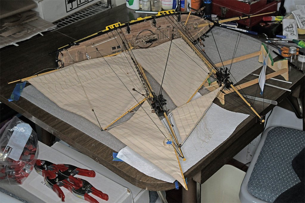
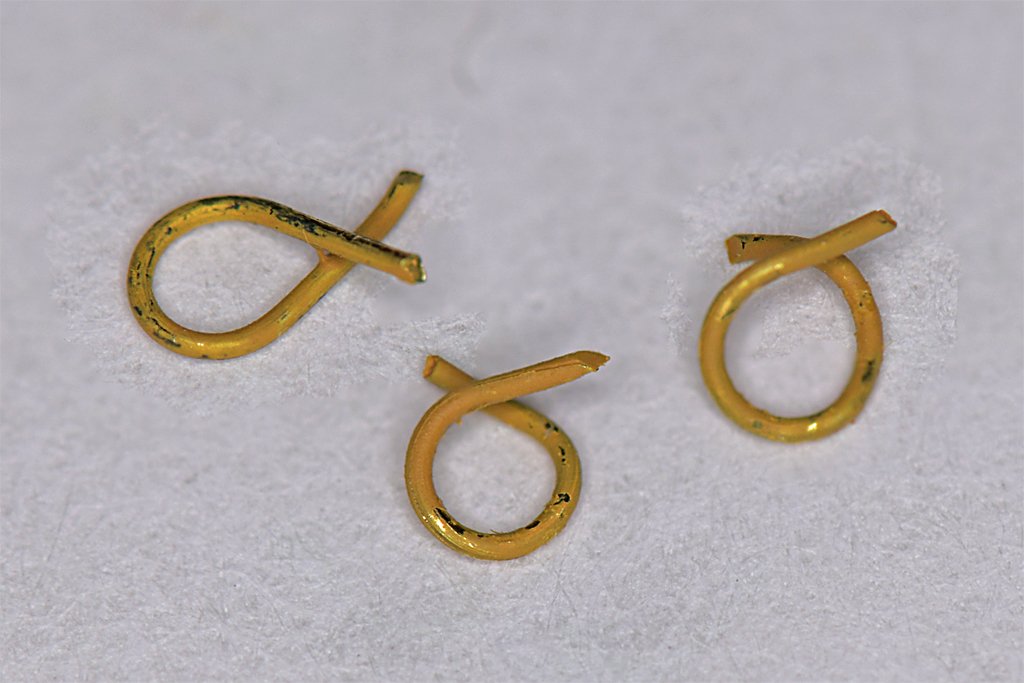
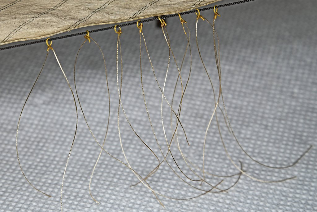
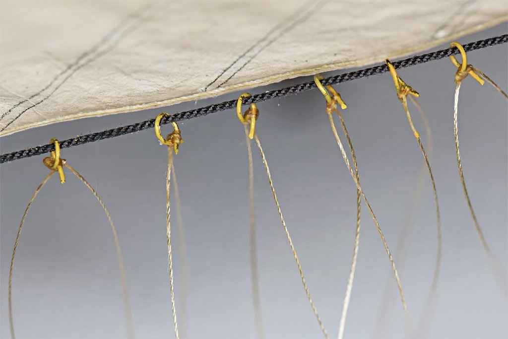
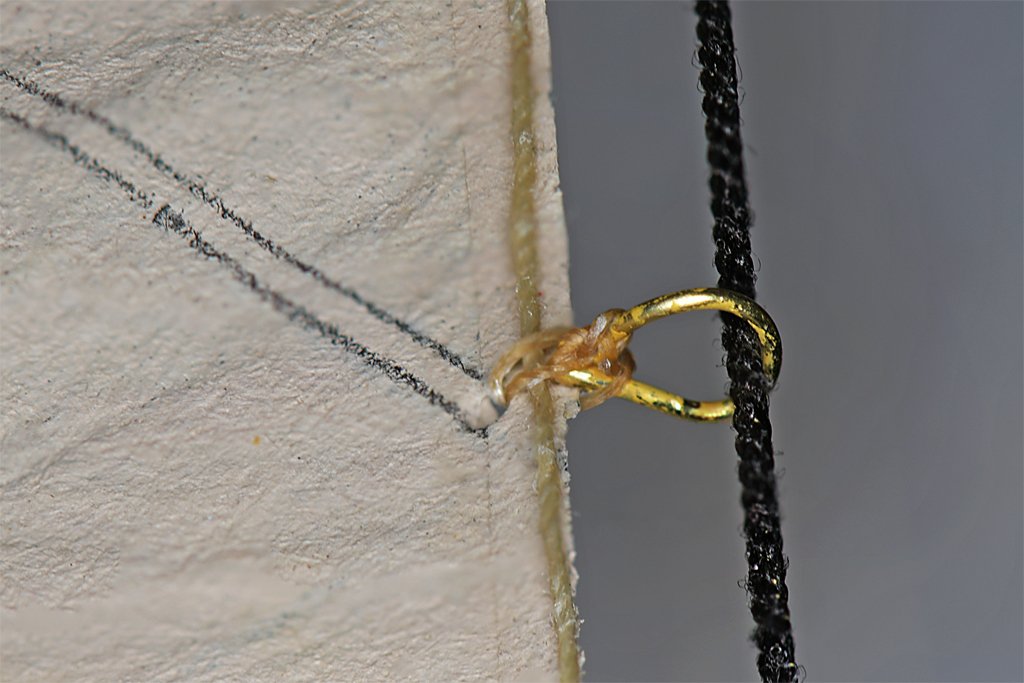
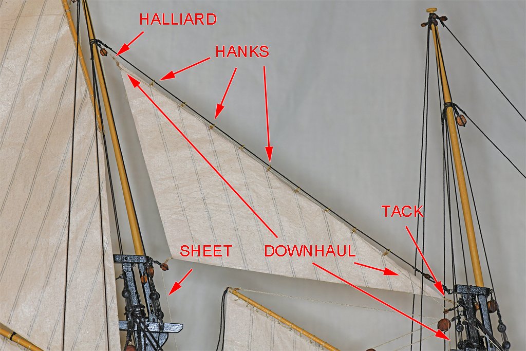
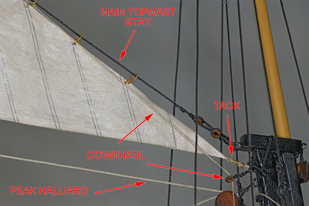
That ^*&@! main sail sheet has been fixed! I have been experimenting with hanks to attach the main topmast staysail to the stay. First I did some research to determine what types of hanks were being used in the early 1800s. I have posted the results of that investigation at this link: https://modelshipworld.com/topic/38044-hanks-for-attaching-staysails-to-stays/?do=findComment&comment=1088102 At the time of my model, about 1815-20, three types of hanks were used, and smaller vessels still laced staysails to stays. I decided that either grommets or wooden hanks would be appropriate for my model. But since I have already rigged the stays putting grommets (three turns of rope around the stay) would be a lot harder that making wooden hanks. I decided to use the wooden hanks. But I think it would be very difficult to work with extremely thin wooden sticks (split bamboo) and get them curved properly. They might want to uncurl, especially when I was trying to tie them in place. So I decided to use 0.012 inch (0.3 mm) brass wire. I used forceps to clamp one end of the wire to a 0.625 inch (1.6 mm) diameter drill bit shank. Then I wrapped the wire around the bit and trimmed off the end, making a "bow tie" shaped loop. These are supposed to be wood so I painted them with the straw color acrylic paint I used on the masts and spars. I really didn't think the paint would stay on while was installing them, but maybe some would. And there is enough remaining on them after they were installed to look something like wood. The first thing I did was lay the ship on its side so the stays would be parallel to the table top. I dreaded trying to fit the hank over a downward angled stay, they try to get it to hold in one place long enough to tie thread around it and then lace the whole thing to the sail. Putting the ship on its side eliminated the problem. The hanks had a gap between the ends wide enough to slip over the stay. Then I closed the gap with forceps. Next I used small (less than 0.006 inch or 0.15 mm) silk thread to tie an overhand knot horizontally across the "X" where the ends crossed and added a small drop of diluted white glue (about 2:1 glue to water). Then the long ends of the thread were looped under the "X" and back through the eye of the hank, and back down again. These ends were then used to tie an overhand knot vertically across the "X". This is actually the way the books show the real hanks being tied. The long ends of the thread were pulled through a small hole in the sail, one from one side and the other in the opposite direction from the other side. The ends were pulled through the hank loop from opposite sides and tied in an overhand knot. Then all of the thread was soaked with the diluted white glue. Here you can see the thread passed around the bolt rope and through the tabling This is important with silkspan sail material, because the thread could easily slice through the silkspan and come loose from the sail. Just as in real sails, it is the bolt ropes that carry the load. I use silk thread for the seizings and other tying. The main advantage is that it goes totally limp with just a drop of water or water based glue. It isn't springy and always trying to unwind. Here is the finished product. The downhaul is tied to the peak cringle on the sail, where the halliard is also attached. The downhaul passes through every third or fourth hank to keep it hanging near the head of the sail along the stay. At the sail tack it passes through a single sheave block and then descends to belay to a pin on the starboard forward pin rail. The sail tack is tied (or hooked) to a ring on a band around the mast head. The downhaul block is also secured to the same ring on the mast band. It actually was pretty easy attaching these hanks to the stay and sail. If you look closely at the photos you will see that some of the paint did chip off of the hanks. But enough remains that the hanks still look something like wood. Four (sails) down and five to go.
-
That's a good use for the anchor davit! We didn't have any lounge chairs on the foc'sle when I was aboard. I'm guessing that you have a motor for the wildcat and windlass. We had to crank it manually to raise the anchor.
- 469 replies
-
- 3
-
-
- minesweeper
- Cape
- (and 1 more)
-
Valeriy, Thanks! I truly appreciate the complement coming from a master modeler like you.
- 469 replies
-
- 3
-

-
-
- minesweeper
- Cape
- (and 1 more)
-
CAD file 3D printing question
Dr PR replied to CPDDET's topic in CAD and 3D Modelling/Drafting Plans with Software
Resizing 3D CAD files is easy. Most (all) CAD programs have scaling functions, and I am pretty sure any 3D printing company can do it. You can even do it on you home PC using free software if you are so inclined. Most likely the 3D files contain scaling information for the size the pieces were originally modeled in (1:12). But even if this wasn't available if you know the desired finished size of some piece - such as the helm (steering wheel) - they can resize the file to produce parts of the desired size. There is a catch to resizing 3D print parts. If you go to a smaller size some of the thinner parts may become too small to print. On the other hand making tiny parts larger may result in really clunky and badly proportioned parts. Check the smallest diameter of the original 1:12 pieces you want to print and halve it for 1:24. Then check with the printing company's minimum dimensions requirements. For example, the outer rim of the automobile style steering wheel in your photo looks to be the smallest diameter part in your photo. Be sure it isn't too small to print at 1:24 or 1:27. -
This is the most unique ship model I have ever seen! Congratulations on finishing it.
-
Johann, I have been following this build and am always impressed with the extraordinary detail you manage to put into the model, especially the rigging. I'll have to think a bit about your belaying needle. I have been pretty lucky belaying lines to the pins in the pin rails on the bulwarks of my model, even though the gaff sails block cross hull access and I have to work blind from the outboard side of the pin rails (I do have a dental mirror, but I need a third hand to hold it). But rigging to the fife rails on the center line becomes difficult as more and more lines enclose it in a web of ropes. I need a tool that is designed to give better control in these hard to reach places and your belaying needle, or a variation thereof, may be the answer. Thanks for posting your build, and for the excellent photos that show what and how you have been making it.
-
Steve, I have a number of ship modelling books that all advise against adding sails. They say the sails detract from the model, and hide some of the deck details. I suppose they might if not done correctly (whatever that means), but I really suspect these guys have tried it and know what a hassle it turns into! I'm sure I won't shelve it permanently. I restarted the 30+ year old build because I got tired of looking at the unfinished model. Having only half the sails on it will be even more annoying! But for now I think I will take a break. The Admiral also "suggests" a break (and you know what a "suggestion" from a superior officer means). I think she is annoyed because she thinks I spend more time on the model than with her. Thanks for all the comments and support. But I'm not sure about that Godfather thing! What am I supposed to do, start rigging a new line and make it an offer it can't refuse?
-
Deck Cleats
Dr PR replied to hof00's topic in Discussion for a Ship's Deck Furniture, Guns, boats and other Fittings
On all the American ship plans I have seen lines with tackles were belayed to eyebolts on deck (near bulkheads or around the base of masts) and the falls were belayed to belaying pins on pin rails on the bulwarks, fife rails around the bases of masts, or to cleats on bulwarks or other places. There are a few other options, but the load bearing parts usually belay to eye bolts. -
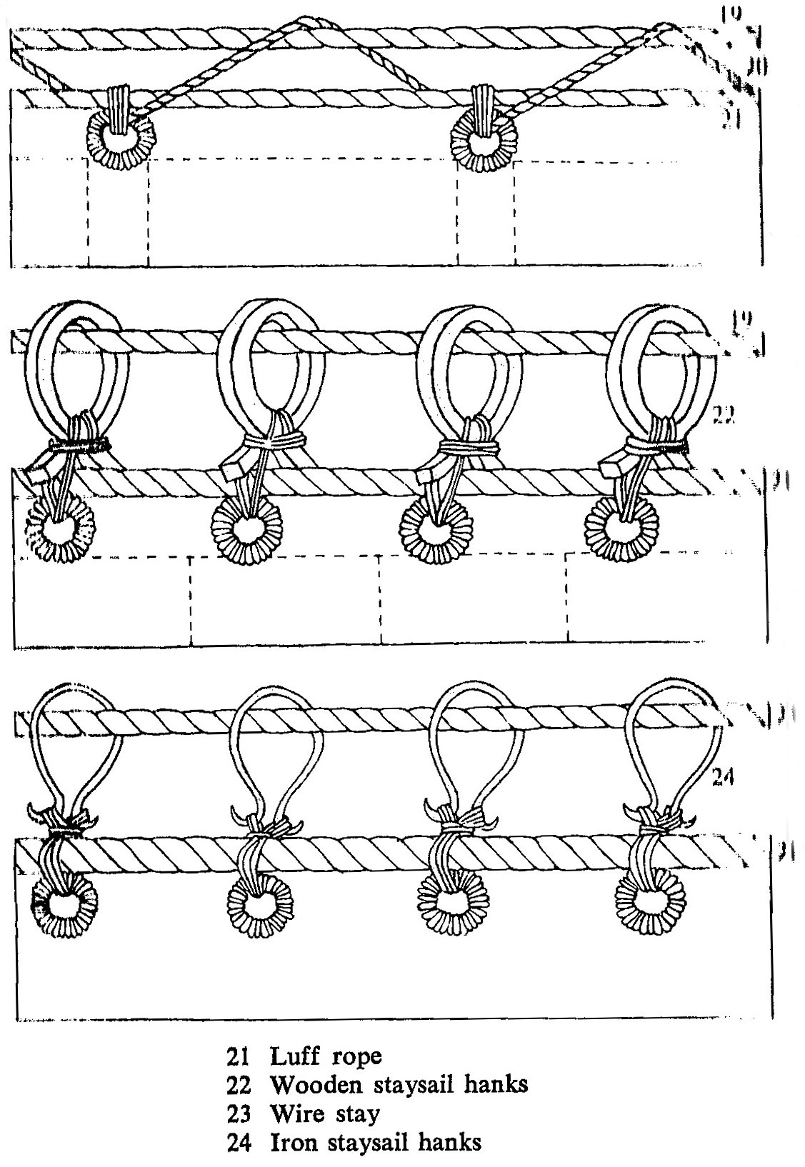
NOTE: Hanks are devices to attach the luff or head of staysails to stays. Some people call the rope coils created when belaying ropes to belaying pins "hanks" but this is a misuse of the term. I am building a topsail schooner model for the period around 1815. I have worked up to rigging the staysails. I have seen a lot of posts on the Forum showing how different modelers have built their models, but nothing that actually considers the different methods for attaching staysails that have appeared with time. I researched the literature I have available and, as usual, found a lot of different opinions. So what should I use for an American topsail schooner (Baltimore Clipper) in the early 1800s? Here is a diagram from Bengt Kihlberg's The Lore of Ships. It shows several methods for attaching staysails to stays. At the top is lacing that is wound in the opposite direction from the lay of the stay. Below that are wooden hanks, showing how they are made, fitted over the stay and tied to the sail. At the bottom are metal hanks showing how they were tied to the sails. Not shown are grommets made of rope to attach the sail to the stay. They were three loops of rope around the stay. I am not sure how they were attached to the sail, but I have seen one instance where the grommet was wrapped around the stay, and then was seized to the sail around the bolt rope similar to what is shown for the wooden hanks. The top two methods are shown using rope stays, and the bottom method is shown with wire stays. But the book doesn't say when each method came into use or for how long it continued to be used. The first place I looked was Howard Chapelle's The Baltimore Clipper and found no mention of how the sails were made or rigged. R. C. Anderson's Seventeenth Century Rigging says "Staysails were laced to their stays with thin lines passed the opposite way to the lay of the rope." Apparently in the 1600s hanks and grommets had not yet come into use and the sails were simply laced to the stays. Falconer's Universal Dictionary of the Marine (1769) describes the following ways to attach staysails to the stays: "GROMMET, ... a sort of small wreath, formed of a strand of rope, and used to fasten the upper edge of a stay-sail to its respective stay, ..." "HANKS, ... certain wooden rings fixed upon the stays of a ship, whereby to confine the stay-sails thereto ..." "They are used in place of grommets, being a later invention ..." " ... framed by the bending of a tough piece of wood into the form of a wreath, and fastened at the two ends by means of notches ..." So grommets were in use in place of the earlier lacing. But by the mid 1700s hanks had come into use to replace the grommets. Steel's The Art of Rigging (1796) says: "GROMMETS. Rings made of worn rope, which are used to confine the nock of spiritsails to the mast ..." "HANKS. Rings made of iron, or hoopsticks bent in a circular form, fixed on the stays to confine the staysails." So grommets were still in use in the late 1700s, but wooden hanks and iron ring hanks were also in use. James Lees' The Masting and Rigging of English Ships of War 1625 – 1860 is a popular reference, but he doesn't mention any vessel smaller that large square rigged ships (even though the English had schooners and such). He says "Hanks ... were usually made of iron, bent round to a bow shackle shape, with an eye in each end ..." "Steel ... describes some made of wood ... but I have seen no model with wooden hanks and recommend the modeler to use the metal type." I question his implication that steel hanks were in use in the 1600s. Darcy Lever's The Young Sea Officer's Sheet Anchor (1808) is my normal go-to for early 1800s American rigging. He says "The FORE STAYSAIL ... is bent to Hanks ... made of ash or iron, and sometimes of Rope." He says about the same thing for other stay sails. He actually doesn't give any details for grommets, wooden hanks or iron hanks. Wolfram zu Mondfeld's Historic Ship Models says "The staysails were bent with lacing or grommets until about 1820, after which time metal hanks seized to the sail were used." No mention of wooden hanks! But he implies metal hanks were used from 1820 on. George Biddlecombe's The Art of Rigging (1848) revised Steel's earlier work for the US Naval Academy. It says: "GROMMET. - A kind of ring, or small wreath, formed of a strand of rope, laid thrice round, and used to fasten the upper edge of a sail to its respective stay ..." "HANKS are wooden or iron rings ... They are used in lieu of grommets." He claims grommets were still used in some instances in the mid 1800s, along with wooden and iron hanks. Harold Underhill says in Masting and Rigging the Clipper Ship and Ocean Carrier "Stay-sails are bent to their respective stays by means of hanks, or metal rings, which enable the sail to slide freely up and down the stay." But he is mostly concerned with vessels of the late 1800s that used wire ropes extensively for standing rigging and some running rigging. Howard Chapelle gives more specific information in his The American Fishing Schooners 1825-1935. "Wooden jib hank for hemp stays ..." "Horseshoe wrought iron hanks for wire rope …" "Wrought iron jib hanks came into use in fishing schooners when wire rope rigging was adapted, sometime before 1885." "Rings were first employed on all head stays..." "Horseshoe hanks came into use about 1887-9." His dates for the introduction of iron hanks are much later than other references, but he is talking specifically about American east coast fishing schooners. Apparently they adopted the "new technology" later than some navies. **** Do I know any more than when I started researching hanks? Well, yes and no. It would seem that new ideas spread slowly, and old ways of doing things hung on for long times. But that isn't new! To summarize, it would seem that staysails were introduced sometime in the early 1600s, and they were originally laced to the stays. By the mid 1700s staysails were attached to the stays with either rope grommets or wooden hanks. But lacing continued to be used into the early 1800s, and maybe later on very small vessels. By the mid 1800s grommets, wooden hanks and iron hanks were used. When iron hanks were introduced isn't clear, nor is the use of iron hanks and rope stays. But it seems they were used with rope stays on larger vessels before wire rope stays were introduced in the mid 1800s. By the late 1800s wire ropes were replacing hemp and other natural fiber ropes, and the hanks used with metal stays were made of metal. What type of attachments were used seems to depend upon the size and period of the vessel, and consequently the size of the stays and sails. Smaller vessels continued to use lacing and rope grommets into the 1800s and maybe 1900s. Wooden hanks were from the mid 1700s up until wire stays were introduced in the mid 1800s. Metal hanks or rings were used on the largest ships perhaps from the early 1700s on through the end of sailing ships, and probably on all vessels when wire rope stays were introduced. For my American topsail schooner I may use rope hanks or possibly wooden hanks. I think metal hanks would be inappropriate, and the ship is probably too large for simple lacing. References Anderson, R. C. 1955. Seventeenth Century Rigging, Model & Allied Publications Ltd, England. page 133. Biddlecombe, George. 1848. The Art of Rigging. Brattleboro, Vermont, USA: Echo Point Books & Media, LLC. Reprinted 2016. Page 15. Chapelle, Howard. 1968. The Baltimore Clipper, Edward W. Sweetman Company, New York. Chapelle, Howard. 1973. The American Fishing Schooners 1825-1935. New York and London: W. W. Norton & Company. Page 507-8. Falconer, William. 1769. Universal Dictionary of the Marine. London: T. Cadell. Kihlberg, Bengt et al. 1975. The Lore of Ships, Crescent Books, New York. Page 118. Lees, James. 1990 The Masting and Rigging of English Ships of War 1625 – 1860. Annapolis, Maryland: Naval Institute Press. Page 37. Lever, Darcy. 1808. The Young Sea Officer's Sheet Anchor. Ottawa, Canada: Algrove Publishing Ltd. Reprinted 2000. page 59. Mondfeld, Wolfram zu. 1989. Historic Ship Models. New York: Sterling Publishing Co., Inc. Page 266. Steel, David. 1796. The Art of Rigging, His Navigation Warehouse, London. page 10. Underhill, Harold A. 1946, Masting and Rigging the Clipper Ship and Ocean Carrier. Brown, Son and Ferguson, Ltd., Glasgow. Page 13.