HOLIDAY DONATION DRIVE - SUPPORT MSW - DO YOUR PART TO KEEP THIS GREAT FORUM GOING! (83 donations so far out of 49,000 members - C'mon guys!)
×


Dr PR
-
Posts
2,439 -
Joined
-
Last visited
Content Type
Profiles
Forums
Gallery
Events
Everything posted by Dr PR
-
 Here is a suggestion for those having "mini" drill presses that have very little vertical clearance. If you have separate drill presses and X/Y tables, first mount the X/Y table on a sturdy base. Then mount your vise on the table. Next mount a spacer block behind the table to raise the drill press high enough so you have adequate clearance above the vise. Mount the drill press to the spacer block. NOPTE: All of this MUST be very rigid. When you lower the drill press to drill the vertical support shaft WILL bend. Period. This will cause some misalignment of the drilled hole. Some of the "mini" drill presses have very flimsy vertical supports. There is a reason industrial mills have huge cast iron vertical supports! The sturdier the vertical support the less flexing will occur. If the drill press is mounted as I suggest above, the amount of bending of the entire assembly depends upon how solid the press is mounted to the spacer block and how solid the block is mounted to the base. But the higher you raise the drill press the greater the amount of flexing you will have.
- 53 replies
-
- 2
-

-
- Drill Press
- Milling
- (and 1 more)
-
A drill press (and milling machine) will drill holes perpendicular to a piece. Because the drilling motion is straight along the vertical axis only you can use extremely sharp and tough, but fragile, carbide drill bits and other very tiny bits that would break if you tried to drill by hand. You can use "V" blocks to hold circular parts in an exact and repeatable position to drill perpendicular through them with precision. If you have a tilting table or vise you can drill at precise angles. Circular tables allow drilling holes in circles, precisely spaced by distance or angle. You can't get this precision and repeatability when drilling by hand. If you have an X/Y table below the drill/mill you can drill a series of holes in precise positions by moving the table the desired amount. This is especially good for drilling a series of holes evenly spaced in a straight line, or lines of parallel holes. Here is a post using a very poor example of a drill press to get a neat series of holes in a pin rail: https://modelshipworld.com/topic/19611-albatros-by-dr-pr-mantua-scale-148-revenue-cutter-kitbash-about-1815/?do=findComment&comment=988816 Here is an example of a simple use for a "milling machine." But in this case I used a drill press: https://modelshipworld.com/topic/19611-albatros-by-dr-pr-mantua-scale-148-revenue-cutter-kitbash-about-1815/?do=findComment&comment=904616 The number of additional tools for milling machines is almost endless, each allowing some precision drilling or milling work.
- 53 replies
-
- 4
-
-
- Drill Press
- Milling
- (and 1 more)
-
I think I recall that Spain has a national maritime museum with some ship plans on line. It might be worth the trouble to poke around on the Internet to see if you can find plans of a Spanish galleon.
-
John, Thanks. I have relearned that lesson! Epoxy is a bit more trouble to mix, and certainly less spontaneous than just grabbing a tube of whatever happens to be lying around. But it would have been quicker to use the epoxy in the first place!
- 464 replies
-
- 3
-
-
- minesweeper
- Cape
- (and 1 more)
-
Keith, I have been soldering since I was a kid - at least 70 years now. I designed electronics circuits professionally and did a LOT of soldering with that. For most solder jobs I have found liquid flux works best. I like the citric acid based flux - it smells like orange juice! You position the parts together and apply a small drop of flux with a brush or toothpick (or similar pointed thing). The flux flows between the pieces. Then you put a small drop of molten solder on the end of the soldering iron and place the drop onto the joint. The liquid flux draws the solder through the joint evenly and quickly. Remove the iron and you are done. If there is extra unwanted solder around the joint I use a small file or a wire brush in a motor tool to remove the solder. The brush also polishes the metal and solder joint.
- 732 replies
-
- 8
-
-

-
- Lula
- sternwheeler
- (and 1 more)
-
Hull planking can be tricky. There is/was no one "right" way. Different shipyards sometimes had different ways of doing things, even on ships of the same class. And different navies had their own ways. When I made my CAD model of the USS Oklahoma City CLG-5 I studied the blueprints and they did not mention a central "king" plank as some ships have. After studying a lot of photos it became clear that there was not a central plank on the centerline. Instead the groove between the two center planks ran down the centerline. ddp is right that there is often a wider border plank or "margin board" around structures and significant deck fittings. And there seem to be a few common ways of joining the pieces of this wider planking. But the blueprints for the USS Cape MSI-2 that I am now modeling are explicit that there is NO margin planking around anything! Instead all deck fittings were placed on the deck planking, sometimes with metal flanges around the fittings (hatches, scuttles, etc.) that rested on the planking. The planking was fitted against the sides of the deckhouse, and then a small wooden strip was attached vertically to the house side with the narrow side resting on the planking. Both the Oklahoma City and Cape were US Navy ships from the middle 20th century. So you need to study the plans and photos of the specific ship you are modeling to determine how the decks were planked (if it had wooden decks).
-
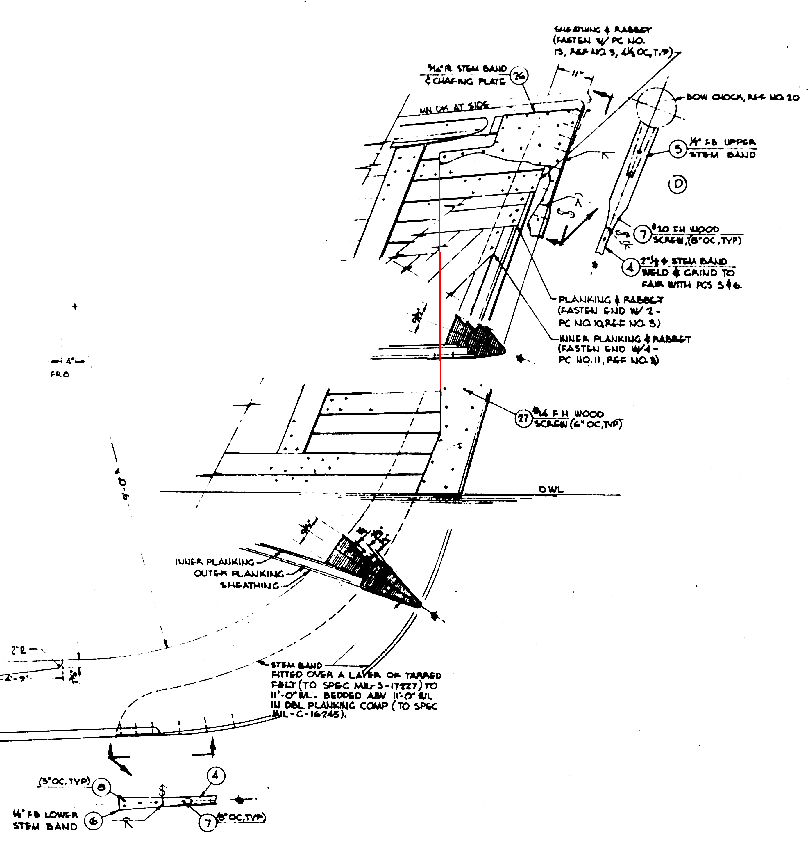
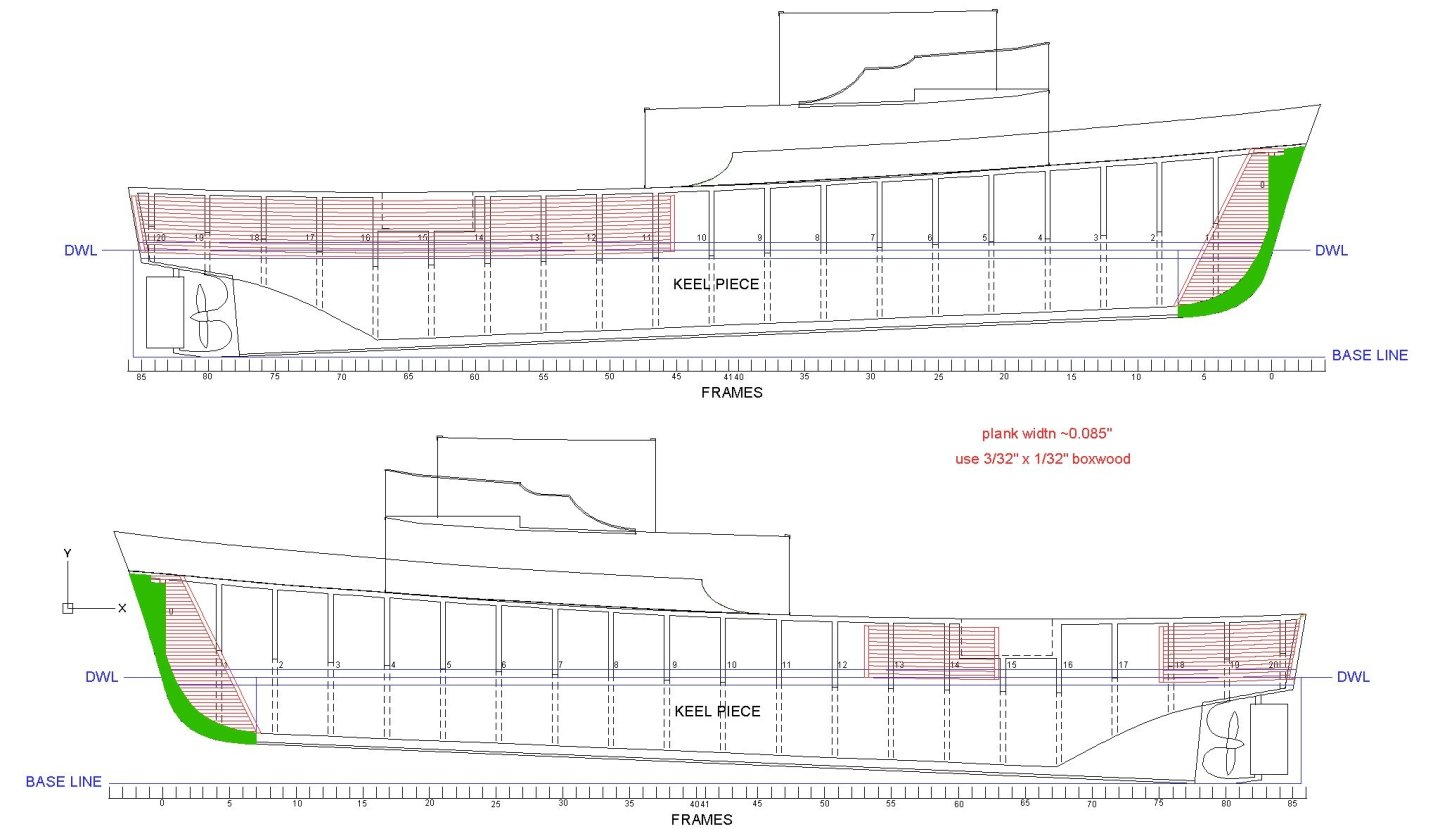
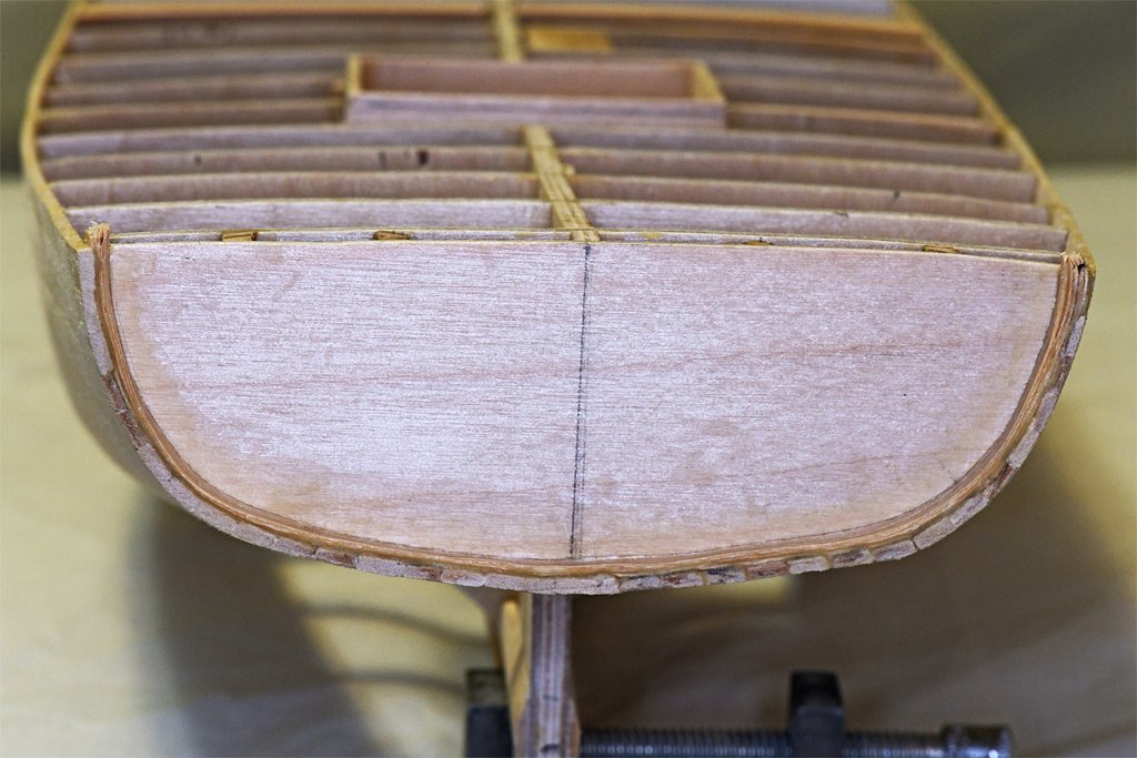
I cut the stem bands from some 0.003 inch (0.76 mm) brass sheet. The metal can be cut with scissors and is easy to shape. But first I needed to decide what the shape would be. Here is the blueprint showing the outline of the stem bands. There are side pieces on either side of the stem. You can follow the vertical left side from the top outline down through the planking detail (red line) to where this edge meets the curvature of the stem. From there it only shows a dashed line down to the keel foot. It shows a curved top end where it turns down to the foot. Notice also the upper stem band, the narrow stem band along the forward edge of the stem, and the lower stem band at the bottom. I have already installed the narrow band along the front of the stem. I will need to add the upper and lower pieces after the side bands have been shaped. One other thing to notice is the cross section "V" shapes of the stem. This will become relevant in the discussion below. The first problem was the shape of the lower end. Austin Cox's photos show a squared off aft end of the side bands. He thinks these bronze pieces are original material. I decided to go with what is shown in the photo of the real hull and put a squared off aft end to the side bands. The drawing (below) shows the dimensions (in inches) of the side pieces. However, when I cut out the pieces I left some extra material on the forward edges. This makes the exact positioning while gluing less precise. The extra will be removed after the side bands are glued in place. First I cut out a paper test piece and fitted it to the hull. I expected to have to make some adjustments to fit the model hull, but the paper part fit perfectly! I scratched the inner surfaces of the brass with number 80 sand paper to provide some "tooth" for the glue to adhere to. Then I shaped the pieces to fit the form of the hull (above). I used Duco Cement (a solution of nitrocellulose in acetone) to attach the brass pieces to the hull. That was a mistake! I have used this glue to attach small brass pieces to wood and it works nicely. But these larger parts had problems. But first I had to hold the parts in place while the glue set - that takes several minutes. When I tried to apply the clamps shown in the photo that "V" shaped front of the stem caused the clamps to slip on the smooth brass surface and pop off the front edge. And they also squeezed the strip, causing it to slip on the wet glue and slide out of place. So I was constantly picking up clamps and putting them back on, while I also pushed the brass strips back into position. As fast as I replaced one clamp another popped off. It was like the Whack-A-Mole game! I eventually found a set of positions where the clamps would stay in place and could relax. I let the glue set overnight, and then removed the clamps. But when I tried shaping the leading edge to remove the extra material the brass strips pulled loose! To make matters worse, one of the brass pieces was damaged while trying to hold things together!! Arrrggghhhhh! To be honest, I thought there was a "small" chance of this happening. I wasn't certain that the Duco Cement was the best choice. So had thought about another option. Plan B When in doubt, use Epoxy! I scraped the glue from the brass pieces and the wooden hull. Then I made another brass piece, and it actually came out better than the first after forming it to fit the hull. They say practice makes perfect. Then mixed up some 15 minute Epoxy. I coated the inner surface of one piece and the mating surface on the hull with thin coats of epoxy and stuck them together. The epoxy was thick enough to hold the brass piece in place while I tried to attach the clamps. The camp at the top - where the hull surfaces are parallel - went on easily. The same is true at the bottom aft end of the piece. But once again it was Whack-A-Mole with the remaining clamps. But this time it was easier. The epoxy was quite messy and I got some on the outer surface of the brass piece when it squeezed out between the parts. The epoxy was much stickier than the Duco Cement, and it actually retarded the slipping of the clamps. The longer it set the stickier it got, and it was trying to glue the clamps to the brass. They still slipped slowly, and I could watch them slipping closer and closer to the leading edge of the stem. So I could catch them when they snapped off and reposition them immediately. After 10-15 minutes they were all holding in place. A couple hours later I repeated the process with the other side. Persistence pays off and I now have brass stem bands on the model. The epoxy did a much better job of gluing brass to wood and the parts do not want to pull apart! I did have to scrape, file and sand off quite a bit of the epoxy that had squeezed from between the pieces. Then I used files to smooth some small wrinkles and bumps in the brass. That was followed by fine grit sandpaper and #0000 steel wool. I will allow it to set over night, and then I will file back the extra material on the leading edge to match the narrow brass strip on the front edge of the stem. I'll add the top and bottom stem band pieces after that and it will be ready for the anchor lining strips at the bow. There is a very complex shape for the bow chock that fits on top of the stem. Right now I don't know how I will make that. But if carving the the stern frame from boxwood turns out OK I may also carve the bow chock and the other chocks from boxwood. If all else fails I can make a 3D CAD model and 3D print them. But I am really trying to avoid using 3D printed materials because I do not know how stable they will be in the long run.

- 464 replies
-
- 12
-
-

-
- minesweeper
- Cape
- (and 1 more)
-
I have seen kits that have masts too long (one of the earliest kits I built had masts far too tall). They look out of proportion, and that provoked Wolfram zu Mondfeld (Historic Ship Models) to make some pretty pointed criticisms of these overly tall models! You mention Anderson's book - are you using his Seventeenth Century Rigging book? He did a lot of research on these vessels so I would use his formulas if you can't find a more authoritative source. There are a few galleon builds on the forum, and these fellows may have more information about the masts.
-
One thing to consider is how small is the smallest hole you want to drill? Mills and drill presses all have some degree of runout (wobble) that limits the precision. If a mill or drill press has too much runout it will break the smallest drill bits. Does the literature for a product tell how much runout it has? If not, it probably has mediocre performance, and might not be suitable for very small drill bits. The main difference between a milling machine and a drill press is in the bearings on the spindle. The bearings in drill presses are designed for vertical (up/down) drilling only - not for lateral (horizontal motion) pressure. Milling machines have bearings designed to allow mill bits to cut through material moving horizontally. You can use milling bits in a drill press, but it will cause excessive wear on the bearings (more wobble, less precision) if you try to mill horizontally. Milling machines may have larger (more powerful) motors because milling takes more power than drilling. And they always have X/Y tables that can be moved with some degree of precision (smaller backlash). They may also have a digital readout (DRO) that allows you to position your work with good precision. You can add an X/Y table to some drill presses.
- 53 replies
-
- 4
-
-
- Drill Press
- Milling
- (and 1 more)
-
" ... large radius edge bend ..." Are you talking about bending the edges of a strip to create a "U" or "L" cross section so it fits over the top and side(s) of the railing? Or are you talking about bending a flat strip by curving it across the wide dimension, as it would be if it was only on top of a curved railing? What is the thickness of the brass? What is the radius of the desired bend?
-
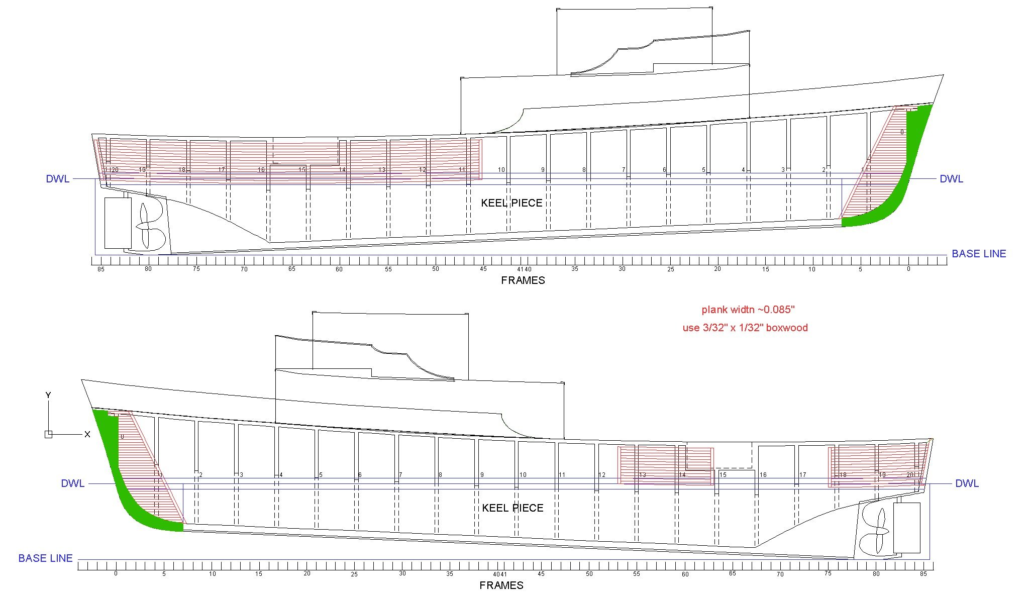
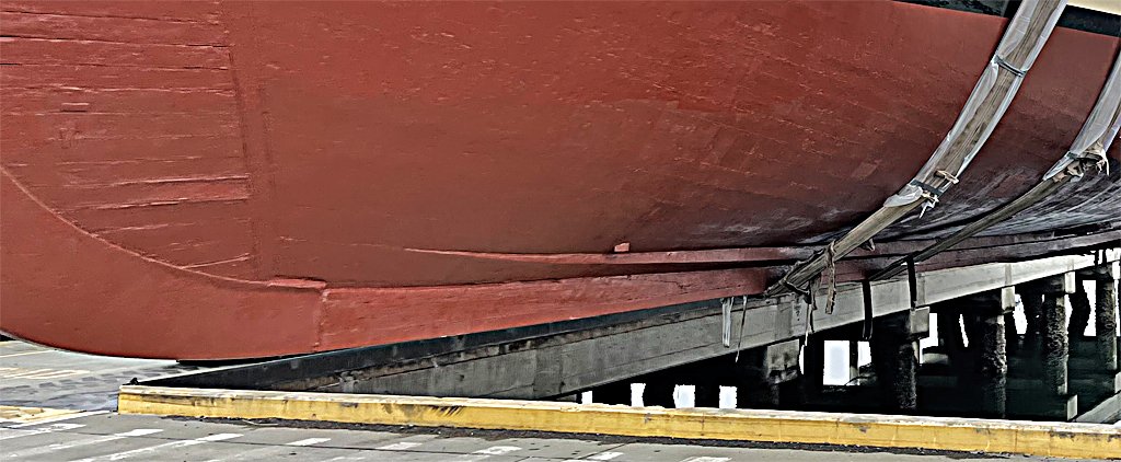
Oops! Wrong again! I thought there was nothing more to do on the hull until the wood for the stern frame arrived. But I forgot about the bronze stem chafing plate and those wooden lining boards on the hull to protect it from anchors, pigs and such. The stem chafing piece is shown in green. I will make it from thin brass sheet. I have several thicknesses in stock, but I think I'll use some 0.005 inch (0.127 mm) pieces in my scrap box. It is pretty easy to work with. The lining boards were a problem. They are not mentioned in the blueprints, so I guess they were added later after wear was appearing on the hull planks. Fortunately I have quite a few photos of the USS Cape MSI-2 and I can see where the linings were located. There was a lot more than I originally thought. The lining planks are shown in red in the drawing above. Note: there seem to be some differences from the linings visible in USS Cove MSI-1 photos. At the bow the linings extended down to the keel - this is evident in the photos Austin Cox sent of the current Cape on blocks. The anchor could bang against the hull here as it was being lowered and raised. From photos of the Cape afloat I can only see the other linings extending down to the boot topping. I am guessing the linings didn't extend much lower because the hull sides curve under at these places and the pigs (floats) wouldn't go very deep. The kites and acoustic sounder could be lowered deeper but would be hanging out over the side. The entire hull did have a thin third outer planking of red oak below the water line and this would provide some protection. I counted the planks in several photos, especially the bow photos, and determined them to be about 4 inches (104 mm) wide. That would be 0.085 inches (2.16 mm) at 1:48 scale. The closest commercially available wood is 3/32 inch (0.094 inch or 2.38 mm) wide. Fortunately, I just ordered 28 feet (8.5 meters) of 3/32 x 1/32 inch boxwood strips. I will need a few feet for trim on the deck house, and the rest was just to replenish stock. Looks like I will have enough for the lining planks! And while looking for drawings of the chafing piece and linings I found one showing 12" x 6" x 1 1/4" (304.8 x 152.4 x 31.75 mm) zinc bars at places on the hull. I knew about the zincs on the stern frame and rudder. But there are two zincs on the "plow" for the engine and fire water intakes! A bit more detail to add.
- 464 replies
-
- 6
-
-
- minesweeper
- Cape
- (and 1 more)
-
SOmetimes a hole is too small for two strands of rope/thread, and a needle threader won't work. In this case just put some glue on the end of the rope/thread and let it dry. Then clip a little bit off the end at an angle. Now the rope/thread will be stiff enough to go through the hole. If the block or deadeye has been painted you may need to open the holes with a tiny drill bit.
-
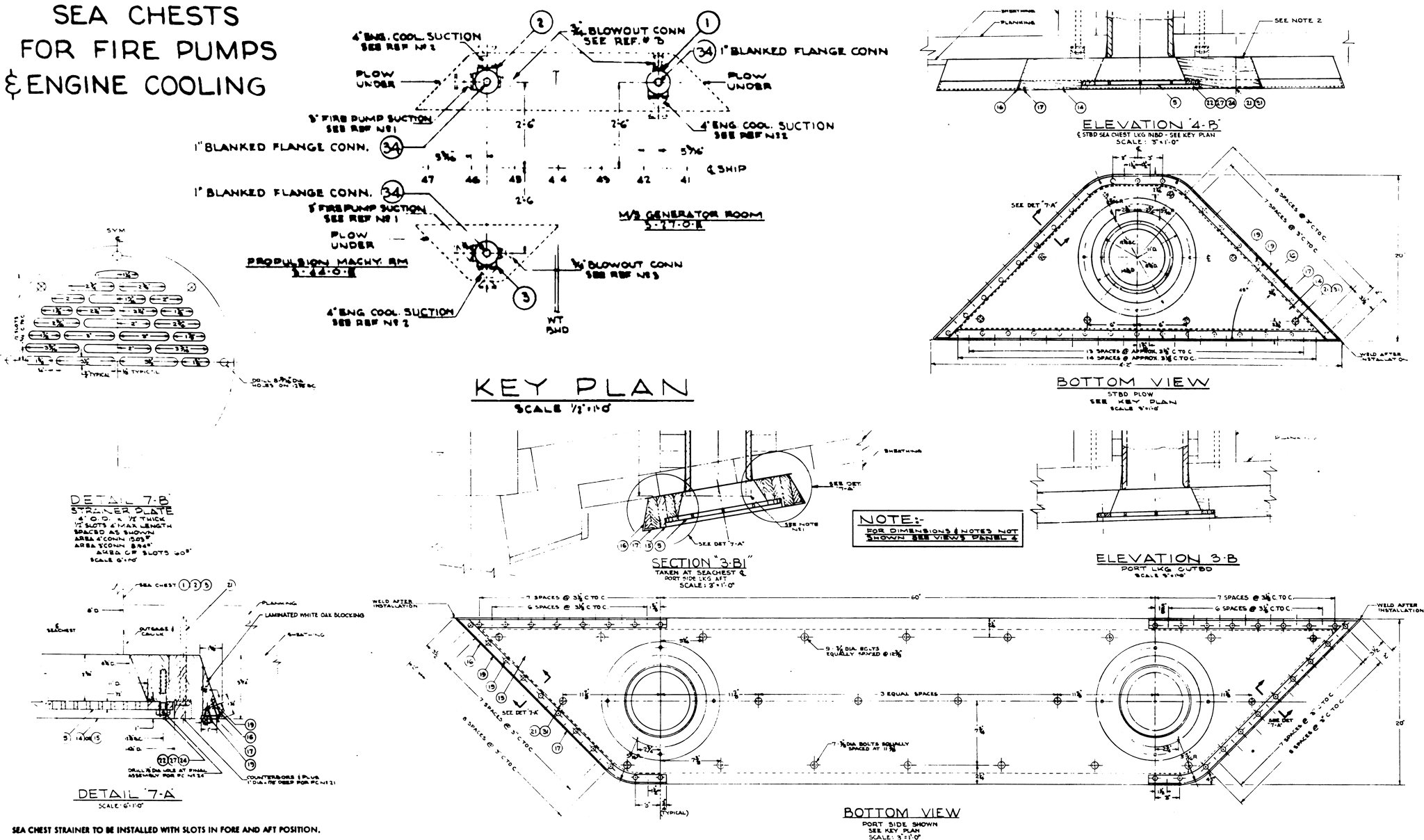
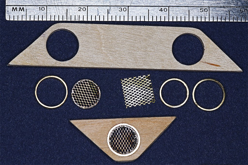
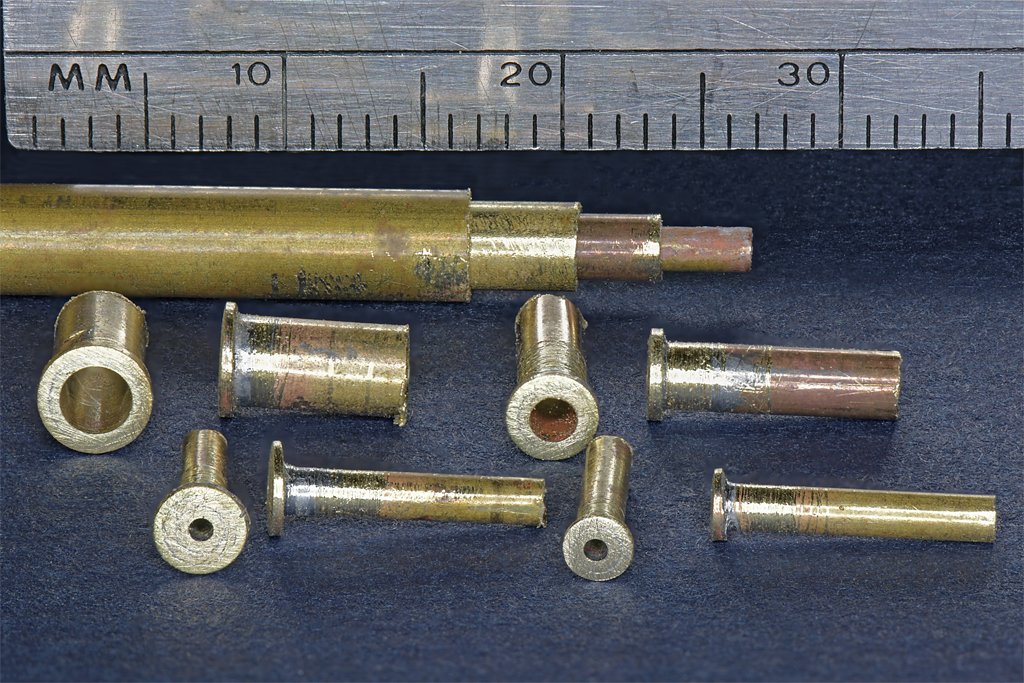
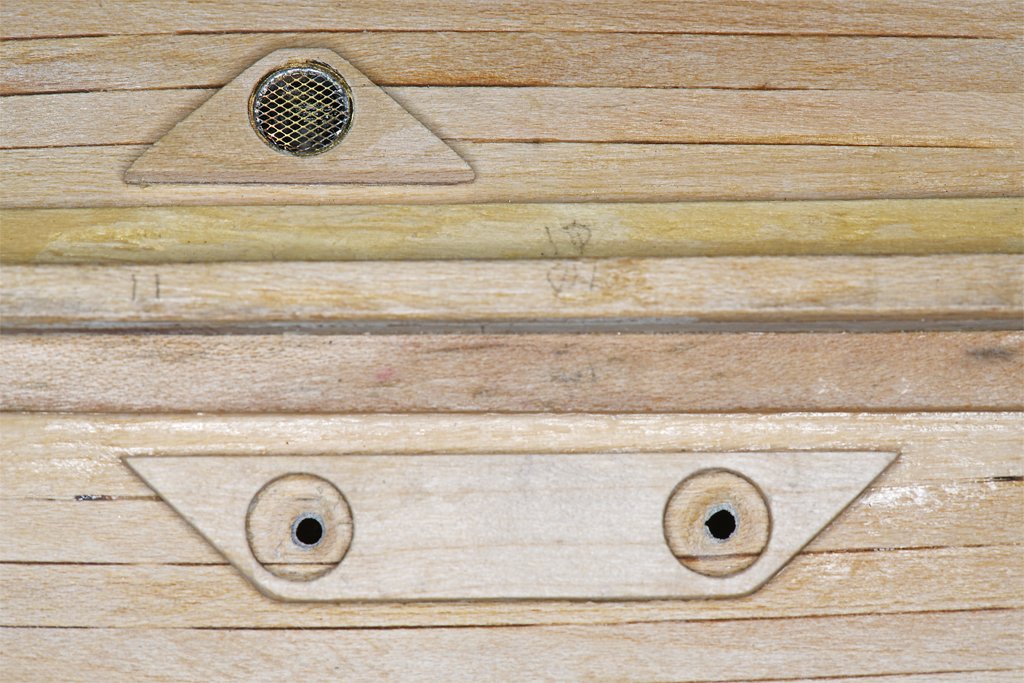
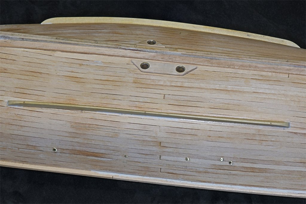
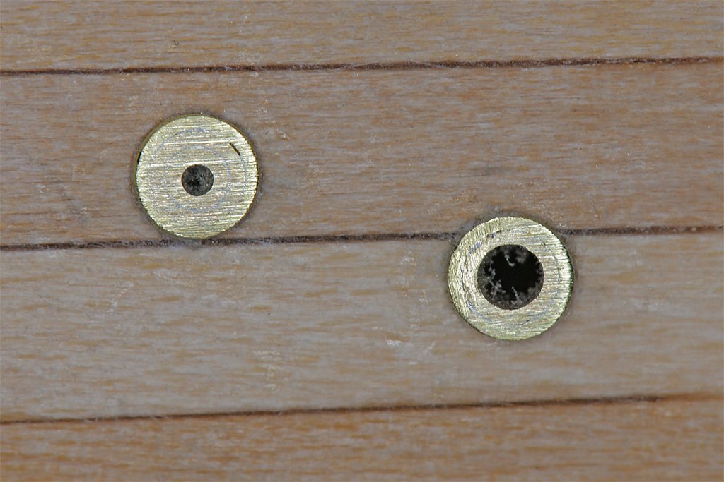
While many of my fellow Americans are having nachos and beer while watching dumjoks chase rubber balls (which I find boring) on New Years Day I have been working on the fiddly bits on the hull while waiting for some boxwood to arrive to make the stern frame around the propeller and rudder. Older wooden sailing ships rarely had deliberate openings in the hulls below the waterline, so there is nothing there to model. But steam and diesel powered vessels have a variety of hull openings, or seachests, that do give us something to model. The original MSI hull had 13 openings (Austin Cox told me he added another for new accommodations). Some were intakes for taking in sea water and the others were various overboard discharges. The intakes for engine cooling water and fire pumps are the most interesting. The openings were surrounded by 3 5/8 inch (92 mm) thick wooden "plows" that were tapered fore and aft to facilitate water flow. An odd thing about these is that they were beveled around the edges with the widest dimensions on the surface away from the hull planking, and not mating to the planking. They were "upside down" trapezoids with the narrow side against the hull plating (see Section "3-BI" above). I'm sure there was some reason for this, but it just seems odd to me. Here is how I made these seachests (see photo below). The plows should be 0.078 inch (1.98 mm) thick at 1:48 scale. I don't have any stock that thick (but some a lot thicker) so they were made of 1/16 inch (1.59 mm) thick basswood with 1/32 inch 0.79 mm) thick plywood glued to the back side. That comes out to 0.94 inch (2.38 mm) thick, so I will have to sand them down a bit. The plywood serves a double purpose. The smaller plow has a large hole for the seachest grating that comes close to the sides. While trying to cut out the opening the basswood piece broke. But with the plywood glued to the back the pieces came together again and I was able to finish the opening. The gratings were cut from very fine HO scale (1:87) brass vent screens for the sides of a GMC F3 diesel engine that I just happened to have in my scrap box. As you can see from the blueprint the grating actually had a series of long, narrow parallel openings, but at 1:48 they would be difficult to create with photo etch. The grating was spot soldered to the end of a 9/32 inch (7.14 mm) outside diameter brass tube ring, and that was soldered into a short piece of 5/16 inch (7.94 mm) OD brass tube. These assemblies were pressed into the holes in the wood. I drilled small holes into the hull about equal to the scale inside diameter of the piping in the original ships, and then used a counter sink bit to make the openings conical, as shown in the blueprints. After the plows were glued in place on the hull I painted the inside if the recess black, and then glued the grating assemblies into the holes in the plows. I used Duco Cement because I have found it adheres to both wood and metal. If you look closely you will see that I did not bevel the edges of the plows undercut as shown in the blueprints. I think this would make the exposed edges of the basswood vulnerable to damage. And in most circumstances these seachests won't even be visible! Why ask for trouble? The remaining 10 seachests were ordinary pipes with flanges attached to the outside of the hull planking. There were six different sizes on the ships, but I don't have a wide enough variety of brass tubing to make them all. Using commercial "telescoping" brass tubing I could make four sizes that are close to scale to the originals. For some I soldered two concentric rings around the end of the center tube to make wide flanges, and some had just one ring for narrower flanges. These were then turned in an electric drill and ground down with files to a flange thickness of about 0.020 - 0.023 inches (0.51 - 0.58 mm). Some of this tubing has been in my junk box for decades and is heavily oxidized and scratched. However, this doesn't matter because only the outer face of the flange will be visible after the seachests are in place. Here are some photos of these seachests mounted in the hull. There is a bit of dust in the openings - I will need to clear that before the hull is painted. But before that the flanges will be filed/sanded a bit thinner to a scale thickness of 1/2 inch (12.7 mm), or 0.01 inch (0.26 mm) at 1:48. All of the seachests will be painted when I get around to that. That is about all of the hull detail below the main deck except for the stern frame. I won't have the boxwood for that for a week or two. So I guess now I will have to guzzle beer and munch nachos while watching a movie. And I will have to start planning the deck house and all of the minesweeping gear that crowds the after deck.

- 464 replies
-
- 13
-
-
-
- minesweeper
- Cape
- (and 1 more)
-
Keith, Very, very nice! Your secret technique (even unknown to you) with the gold paint produced an interesting "hammered" effect. The result is beautiful! Happy New Year!
-
Tom, I'm not sure we were really looking for a helicopter. That is just something I overheard in the preparations for getting underway. It may be that the only person onboard who really knew what we were looking for was the fellow in the sonar shack. The whole episode was mysterious. The original message just said to get underway immediately, but didn't say where we were going or why. "Men, I want you to leave immediately!" The CO did get verbal orders to go look for something. No one told me what we were looking for, but I was told that the sonar shack guy would tell us if we found something. Everything about the sonar was classified. And we couldn't be seen searching in daylight (at night we looked like just another fishing boat's navigation lights). Weird! But whatever we were looking for we didn't find.
- 464 replies
-
- 3
-
-
-
- minesweeper
- Cape
- (and 1 more)
-
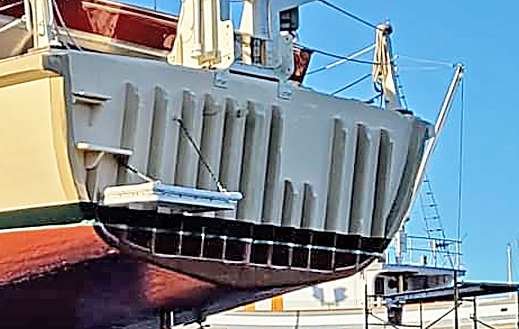
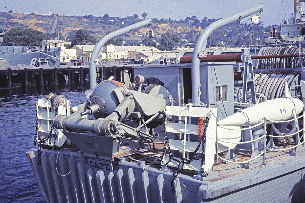
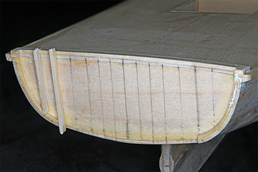
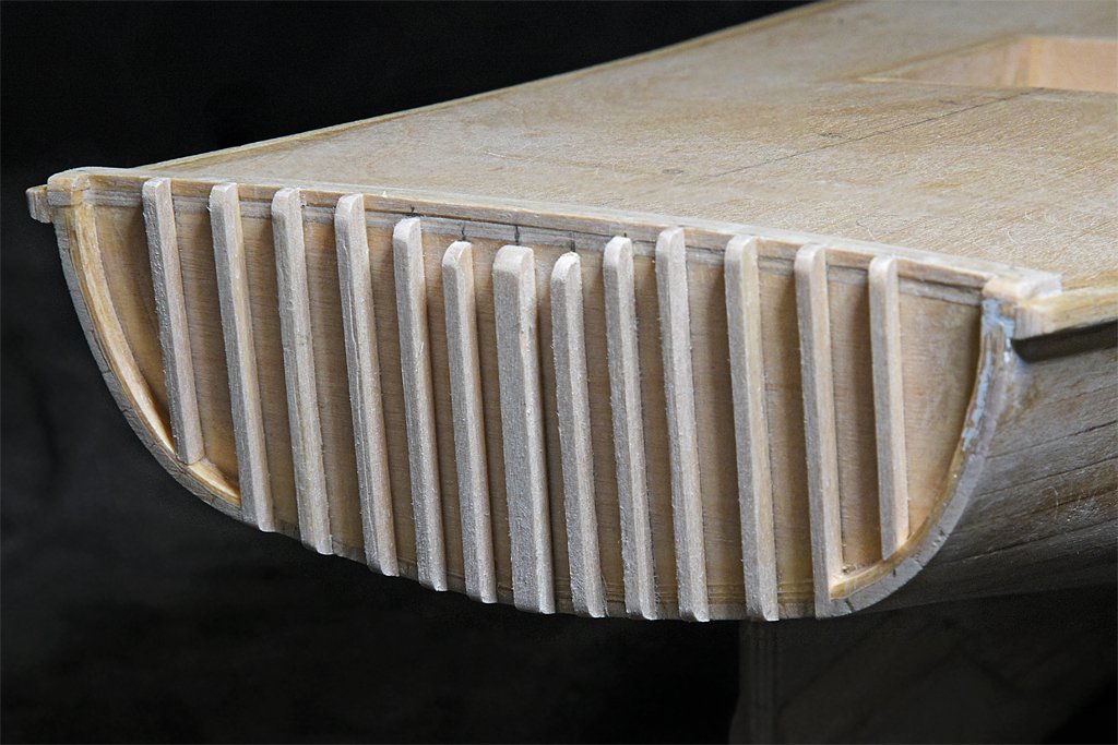
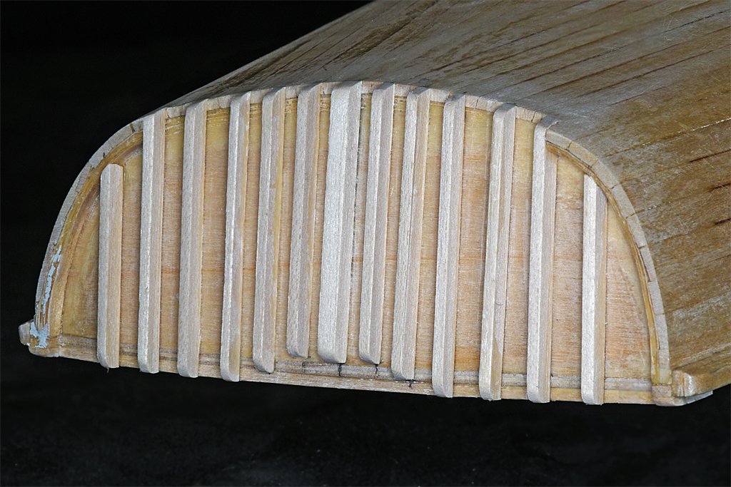
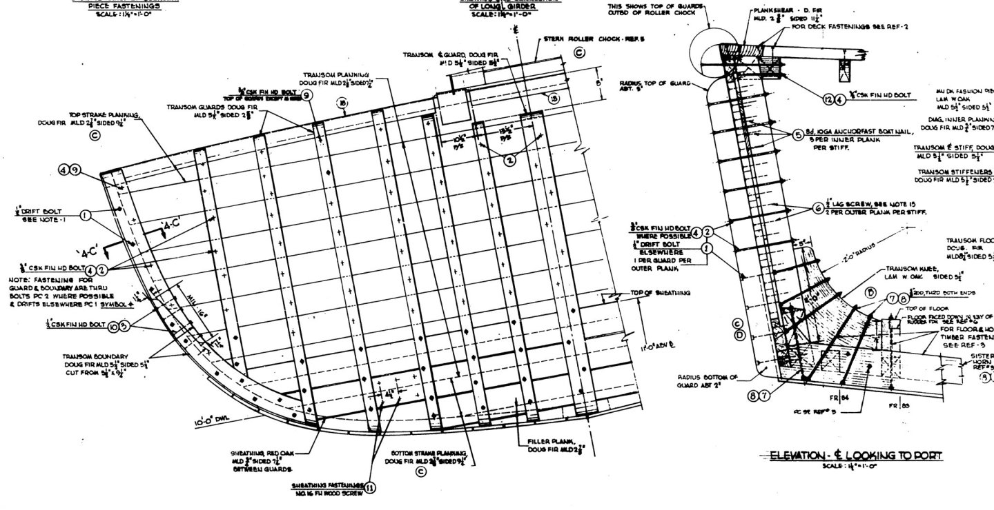
Tom, My wife started early (18) in a previous marriage. And our oldest son married a slightly older woman with two young kids. All together that makes for several generations of rug rats. I have been making bits and pieces as I go along, ahead of when they will be installed. The plankshears and nibbing strakes are some of these pieces. Here is a photo. The plankshears are the wider outboard pieces and the nibbing strakes are the inner parts. The straight piece in the center is the stern plankshear. I didn't want to try to bend a 0.31 inch (7.9 mm) wide wood strip across the wide dimension so these pieces were all cut from a large 1/16 inch (1.59 mm) thick sheet of basswood. And that brings us to the latest work. I needed the stern plankshear piece to finish the transom. Mr. Cox sent the photo (left above) that shows the transom of the current Cape. The top of the vertical "guard" pieces end below deck level, and the bottoms merge into a horizontal member at the bottom of the transom. But the original blueprints (right above) are quite different. Most of the guard pieces extend up to the stern planksheer piece, and all but the outermost two on each side extend down to the bottom of the hull. So there have been a few changes to the vessel since it was originally constructed. I want to model the ship as it originally was - as a minesweeper - so I will follow the blueprints. I originally thought I would make the stern like the current vessel so I extended the planks and built up the piece all around the edges of the transom (left above). However, when I finally figured out how the blueprints showed it I trimmed back the edge part to extend only to the second vertical piece from the outer edge of the transom (right above). The other vertical pieces were glued in place (below) as shown on the blueprints. The vertical guard pieces protected the transom when we were streaming minesweeping gear and hauling it back in. The heavy pigs (floats), otters (pull the sweep cable down below the pigs) and kites (pull the cable down at the ship's stern) were suspended from derricks while rigging the gear and could swing around wildly in heavy seas, banging against the hull. I will describe this gear in detail when I get to that part of the build. And this brings us to another episode of DrPR's Story Time Once upon a time on a slow day when nothing much was happening the Cape's Captain, Executive Officer and I (Ensign Fuzz) went over to the Long Beach Naval Station's Officer's Club for lunch. Afterward the CO and XO went to the Base Exchange while I wandered back to the Cape. When I got to Pier 9 I saw a large crane on the pier beside the ship. It was lifting the stern minesweeping roller chocks from the ship. Our Chief Bosun's Mate (senior enlisted on board) was on the pier. "What's going on?" I asked. He handed me a piece of paper with orders to get underway IMMEDIATELY as soon as the sonar was ready! Sonar? The Cape didn't have a sonar - well, normally, that is. But the Bosun explained that occasionally we would take aboard an experimental mine hunting sonar for testing. That was news to me! Here is a photo of the SQS-16 sonar installed on the Cape's stern, along with the control shack just forward of it. The sonar is the spherical thing with something sticking out of the bottom. Unlike most sonars up to that time, the SQS-16 didn't just send out a "ping" and measure the time for the return echo to determine distance. This thing used a very high frequency acoustic scanning "beam" to create a picture on a video screen. The resolution was good enough to see nuts, bolts and other small features on the objects being viewed. It was bleeding edge stuff, and that is why it was classified SECRET. You can also see that the vertical guard pieces on the transom were actually installed as the blueprint shows, and details of the stern ends of the horizontal guard rails. The white things on either side at the stern are the ordinary minesweeping otters and kites, and you can see one of the pigs on the starboard side aft. If you look closely you can also see some of the additional horizontal "lining" planks added to the exterior of the hull planking to protect the hull while the pigs were being lowered and hoisted over the side. Well, we weren't going anywhere - orders or not - until the Captain returned. Fred would have been really POd if I left without him! After a while he and the XO came walking up the pier. Imagine his surprise to find the lines all singled up, the engines running and the gang plank ready to be hauled in! So off we went! But where were we going? This reminds me of a scene from the movie Le Roi de Coeur (The King of Hearts) where the WWI Scottish Colonel asked for three volunteers. When they arrived he said "Men, I want you to leave immediately!" "Sir!" they replied, saluting. And then they all ran away. "Stop!" the Colonel shouted. "Where the devil do you think you are going?" "No idea, sir!" came the reply. The CO made a call to the Squadron headquarters and learned we were supposed to motor down the coast to San Diego and hunt for something in the waters off Point Loma. The Captain said it was a downed helicopter, and there was something aboard they wanted to recover. Then after a quick call to his wife to say he wouldn't be home for dinner we cruised out of Los Angeles harbor and headed south. It was about 1600 (4 PM) before we actually got under way and well after dark when we got to San Diego. We received the coordinates of two rectangular areas we were supposed to search where the "helo" might have gone down. The first was just a mile or two off the beach at La Jolla, just north of Point Loma. Our search pattern was just a series of parallel courses a few miles long. At the end of each leg we did a 180 degree turn and proceeded back parallel to the previous leg. Simple, right? So simple that after a while the CO took to his bunk leaving Ensign Fuzz to complete the search area. I had only conned (driven) the ship a few times, and that was just around Catalina Island or such while the crew fished. This was different, because we had to proceed in straight lines proscribed distances off shore. Every couple of minutes I used the ships' surface search radar to get distances to shore, and visual triangulations to points ashore to locate our position. The positions were plotted on a chart so I could estimate the timing of our next turn. But the fact that we had to conduct the search at night complicated the visual sightings - I had to locate certain reference lights that I was not familiar with against the background lights of a large city! But I figured this out and we were going along smoothly, except for two major problems. First, the sonar sphere was dangling directly off the stern in the propeller wash. If we went too fast the sonar cable would twist and turn, making it impossible to get a picture and determine the bearing to anything spotted on the sea floor. And remember, the USS Cape was about as maneuverable as the Rock of Gibraltar at low speeds. We barely had steerageway (fast enough for the rudder to work). The second problem was the Black Current (Kuroshiro or Japan Current) that flows from north to south down the Pacific Coast of North America. It streams close to shore at Point Loma, right where our search area was. Even with our bow turned into the current we moved backwards! Add to this that there were kelp beds inshore that would tangle and foul the sonar that I had to avoid. It was nearly impossible to steer a straight course (especially for a novice like me)! Instead of a set of nice parallel course lines on the chart there was a scribble of zig zag lines, but I did cover that search area thoroughly! There was no helicopter (or anything else of interest) there!! I was proud of myself for having accomplished the assigned task. The CO came back to the bridge about dawn and asked if we had finished the search areas. Areas? All I knew about was the one. But apparently he had expected me to search both areas before dawn. He was upset! When I asked what the problem was - we could still search the other area - It seems we weren't supposed to be seen searching the areas in daylight. Why? Your guess is as good as mine! It was another McHales Navy moment. Happy New Year!

- 464 replies
-
- 5
-
-
-
- minesweeper
- Cape
- (and 1 more)
-
Richard, I too was surprised to find the planksheer boards wider forward of frame 51 than they were aft. I am guessing that the wider planksheer forward was to accommodate the bulwark supports and fastener hardware up forward. There is no bulwark back aft. Another surprise was the nibbing strake inboard of the planksheer that is the same width from bow to stern. The deck planks are not nibbed into the wider planksheer but into this separate nibbing strake. And to add to the fun the forward and aft planksheers are scarfed together along with the nibbing strakes to create a pretty gentle transition at frame 51. I still haven't figured out exactly how this will work.
- 464 replies
-
- 1
-
-
- minesweeper
- Cape
- (and 1 more)
-
See reply #8.
-
I was trying to use the shellac to shape the rope. Shellac is an alcohol solution. Fiebing leather dye is alcohol based. If the alcohol in the shellac wicked down the ropes to the blocks the dye bled into the ropes, discoloring them. I also had problems with the light brown stain on the wooden blocks. The end grain is more porous that the side grain, so the ends of the blocks soaked up the stain and are almost black. The sides stained OK on the smaller blocks, but the sides of the larger blocks were splotchy. I think this was caused by glue on the wood from the sheeve pins in the multi-part Syren blocks. All in all, I think I would have gotten MUCH better results with just painting the blocks.
- 714 replies
-
- 3
-
-
- lady nelson
- victory models
- (and 1 more)
-
White school glue (Elmer's Glue-All) dries totally invisible, so it might be good for gluing your rope coils to the deck. It does take a while to set. Many people dilute it 1:1 with water to thin it so it flows better.
- 436 replies
-
- 1
-
-
- Syren
- Model Shipways
- (and 1 more)
-
John, Must have been really important to interfere with ship modelling. Happy holidays!
-
vossiewulf, The "jib inhaul/outhaul/halliard ring thingy" is called a "traveller." There are some other things called travellers, most (all?) involving metal rings that slide along some kind of boom or rod and provide a place for tackle and rigging to attach to - like the ring that the boom sheet block will attach to on the "horse" (horizontal metal bar) at the stern of your model. You must have great patience to be manually serving ropes with that very tiny thread! Your bock holder is a nifty idea. I'll have to make one for myself when I get back into rigging. Have a happy holidays!
- 714 replies
-
- 4
-
-
- lady nelson
- victory models
- (and 1 more)
-
What? No pictures of Grandma and Grandpa on the wall? Very nice Keith. I'm sure it will see a lot of playtime!