HOLIDAY DONATION DRIVE - SUPPORT MSW - DO YOUR PART TO KEEP THIS GREAT FORUM GOING! (83 donations so far out of 49,000 members - C'mon guys!)
×


Dr PR
-
Posts
2,439 -
Joined
-
Last visited
Content Type
Profiles
Forums
Gallery
Events
Everything posted by Dr PR
-
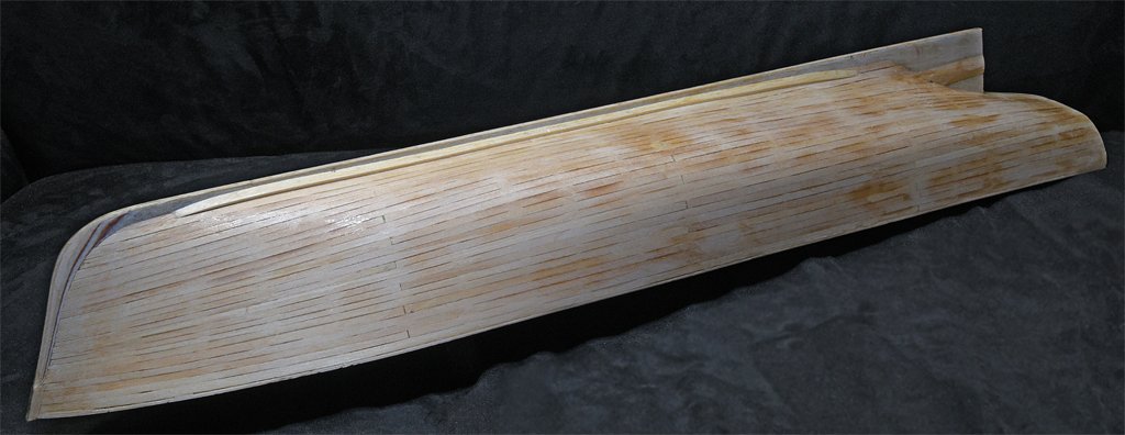
 The guards are now shaped to the proper angles. I am researching sea chests and a few other small details for the hull before going on to the last major piece - the stern frame that holds the propeller and rudder. I haven't decided what material to make if from. I could carve it out of Castello boxwood. That would be easier than cutting if from a brass or aluminum bar. I am continuing to apply thin layers of acrylic sealer and then sand the hull smooth with fine grit sandpaper. I don't plan to apply paint until after the stern frame is installed and all the other hull details are finished. There will be a pause in construction while I spend some time with kids, grandkids and great grandkids and enjoy Christmas.
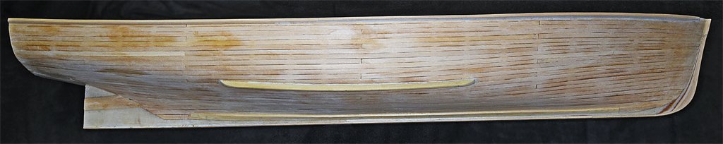
- 464 replies
-
- 12
-

-

-
- minesweeper
- Cape
- (and 1 more)
-
Wealck, Thanks. I have some rasps but they are far too aggressive for finish work. The riffler files would come in handy for concave surfaces.
-
Adrian, I have used single edge razor blades to scrape wooden decks on earlier models. But not until I started my current MSI model did it occur to me to use scrapers (and files) to do fine shaping on concave parts of hulls. I have spent a lot of time shaping this latest hull and I can find no visible or tangible surface irregularities, especially in the most convex parts that are hard to shape with sanding blocks. Of course the truth will come out when I apply the first coat of opaque primer or paint!
-
Thermal effects are important, and the larger the model the greater the effect. A fellow in Australia made a 1:72 R/C model of an aircraft carrier that was about 4 meters (4 yards) long. He made the hull framing and structure out of wood and the decks and hull sides were styrene. Wood has a low coefficient of thermal expansion (how much a material expands with temperature changes) and styrene and other plastics have relatively high coefficient. The decks were painted dark gray, and when the model was out in the sun the plastic warmed up - especially the flight deck - and expanded. With a 20 degree Celsius change 4 meters of styrene will expand about 5 mm (1/4 inch). Unfortunately the flight deck was anchored well to the wooden frame at the bow and stern so the plastic could not get longer. Instead the deck bowed up seriously, and the side plating pulled loose. In just a few minutes months of work were wrecked! You would think that a 3D printed model would not have any problems since the entire structure is made of the same plastic material and should all expand/contract evenly. However a R/C model will have the lower part of the hull in cool water and the upper parts will be exposed to sunlight and heated - especially if the decks are painted dark gray. At some model length this has to be taken into consideration or the hull will "hog" (become banana shaped) if the top expands faster than the bottom. The stresses might cause it to break apart. This is a consideration for real ships. In theory the steel hull of the 610 foot (186 meter) cruiser I was on could vary in length about 5 inches (127 mm) between arctic and equatorial waters. Actually it would be a bit less than that because the hull interior was heated in cooler areas and cooled in warm waters.
-
Valeriy, I hope your customer will be satisfied with this! It certainly is a beautiful model.
-
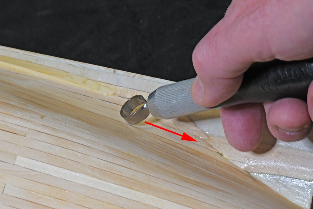
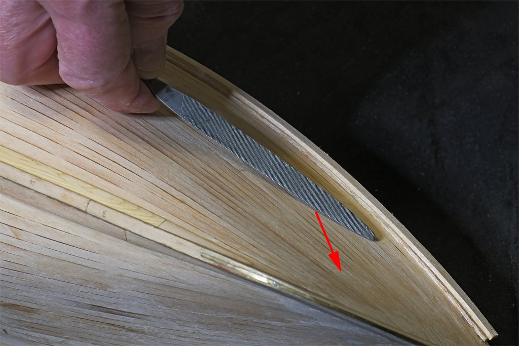
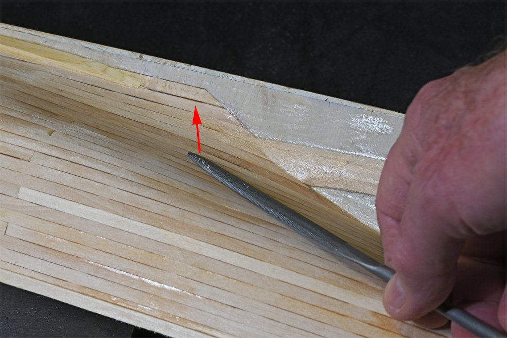
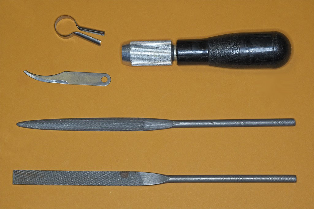
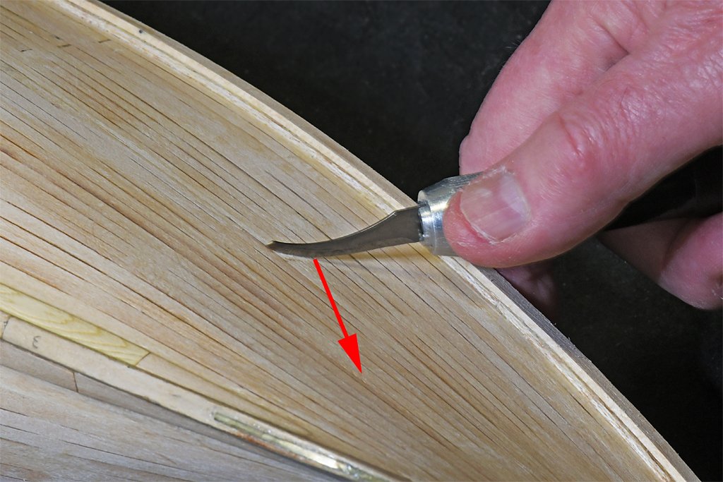
I often see comments about using sandpaper to smooth wood hull and deck planking. Sometimes files are used to shape pieces for deck furniture and such. Occasionally someone will mention scrapers, but not much more is said about them. But files and scrapers can be very useful for shaping hulls, especially on the concave (inward curving) surfaces where flat sanding blocks are of limited usefulness. Here are four tools I find indispensable for putting the finishing touches on the surfaces of a planked hull. I bought the top two blades and the handle decades ago in a set, along with several more common blade shapes. I could see how the curved knife blade could be useful for cutting things, but I had no idea how the loop blade should be used. The two files are fairly common shapes. The top one has one flat side and the other side is curved, forming a flattened "D" shape. I could see how it would be useful for cutting "U" shaped grooves in pieces. The flat rectangular file is useful for just grinding away material, as is the flat side of the other file. But I have learned there are other ways to use these tools. First consider that curved file. You can use the curved side to shape concave surfaces with an ordinary back and forth motion along the length of the file. But this can cut grooves into the wood if you are not careful. The long curved edge of the file can also be used to cut much gentler curves more closely matching the curvature of the hull. Move the file at an angle to the length of the file, holding the edge in contact with the wood. By rotating the file around its axis you can change the curvature where the cutting edge contacts the wood to match subtle changes in the curvature of the hull. If you use the file flat side down, and rotate it a bit, you can change the cutting angle from straight (flat against the wood) to the full curvature of the file edge. The tip can be very useful for removing small imperfections. Again, move the file from side to side, holding the edge of the tip against the surface. You can see in the picture where the hull surface has an "S" curvature where it goes from a convex shape around the hull side through a concave curve to meet the keel and deadwood near the stern of the boat. You can use curved sanding blocks in these concave areas, but the curved files are better suited for working in these tight varying radius curves with neighboring surfaces. OK. Now what about the scrapers? You may have seen posts about the very specialized (and expensive) scrapers used by luthiers (stringed instrument makers) and furniture makers. These often have specially prepared curved cutting edges to allow the same curves to be repeated over and over. But just about any reasonably sharp knife blade can serve as a scraper. First of all, scrapers usually produce a cleaner surface with less raised wood fibers and none of the parallel scratches that sandpaper leaves in the wood. And the scraper blade can work in tight spaces where a sanding block isn't suitable. A straight or square-ended blade (like a single edge razor blade) is very good for smoothing deck planking. A curved blade is useful as a scraper on concave surfaces. As shown here, hold the blade perpendicular to the surface and drag it sideways over the wood. The blade will scrape material from the high spots only, bringing them down to the level of lower areas. This is especially useful where you have planks of varying thicknesses, or plank edges that rise above the surrounding planks. I finally figured out how to use this strange cutting loop. By holding the cutting edge at an angle to the surface and dragging along it will make a shallow "U" shaped cut. The greater the angle of the blade to the surface the shallower and broader will be the cut. But you must use only slight pressure so the blade doesn't cut deep into the wood! Sand paper and sanding blocks sometimes just remove the edges of raised planks, leaving the surface rippled with smooth surface between higher and lower planks. This loop scraper will remove the "crown" of the higher plank. You can also drag it at an angle to the plank length to remove small bits at the highest points. I was surprised at how useful this tool is for removing very small amounts of wood in small areas. The trick to getting a very smooth hull surface in curved areas is to hold the surface at an angle to a bright light so low spots show up as slight shadows. I use these files and scrapers to remove material from the high places surrounding slight depressions until the shadows disappear. An even more sensitive way to detect slight imperfections in the surface is to drag your finger back and forth over the wood. You may be surprised that you can feel imperfections that don't appear as shadows. And this is the way to detect slight irregularities in the curvature that are never visible. In these cases you must remove only very tiny amounts of wood while smoothing the surface. Cut a bit, feel a bit, and continue until you cannot detect anything amiss. After you have used the files and scrapers to get the "perfect" surface it is best to go over it with very fine sandpaper or steel wool to remove any tiny scratches. CAUTION: Be careful to avoid repeated shaping in a single spot (with files, scrapers or sandpaper) until you have removed all of the wood and make a hole in the planking. If you have a deep dent or plank edges that rise very high it might be best to add material to the low spots before you start removing the highest parts. I sometimes glue thin wood shavings (made with a plane) into low spots and sand them down flush with the surrounding areas before starting the final shaping.
-
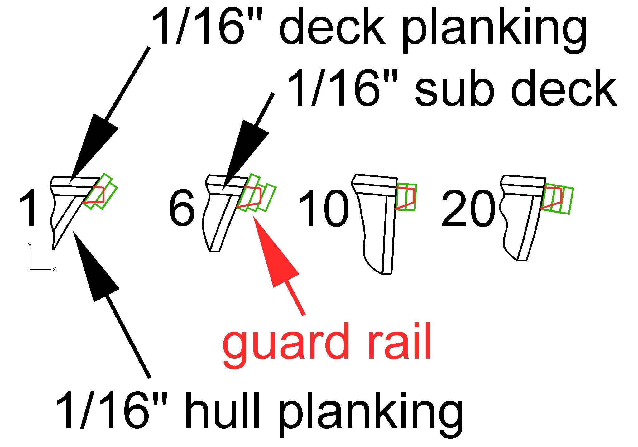
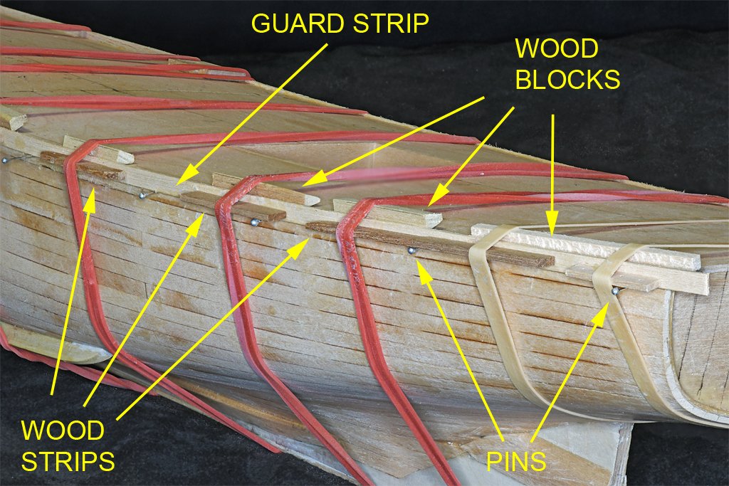
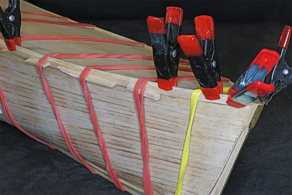
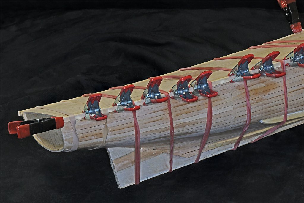
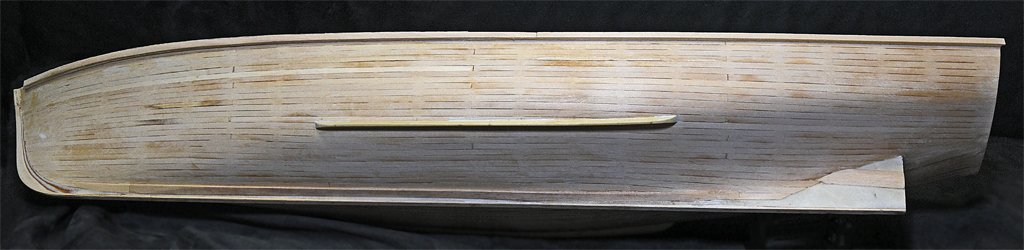
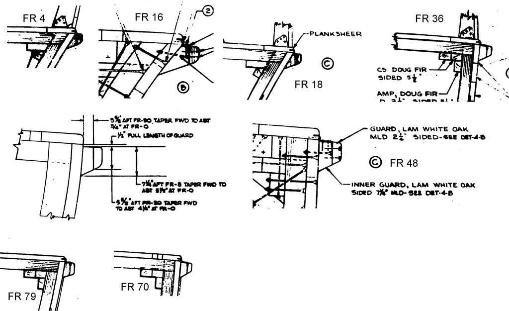
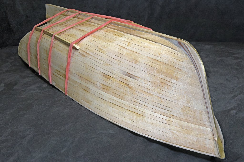
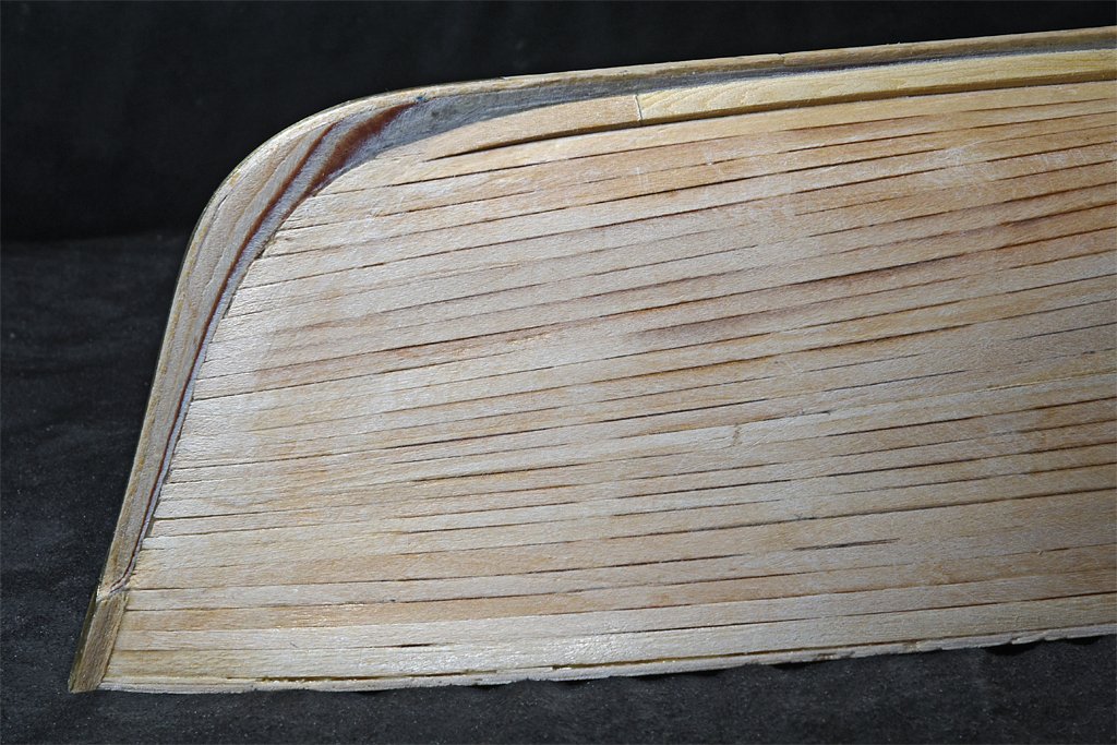
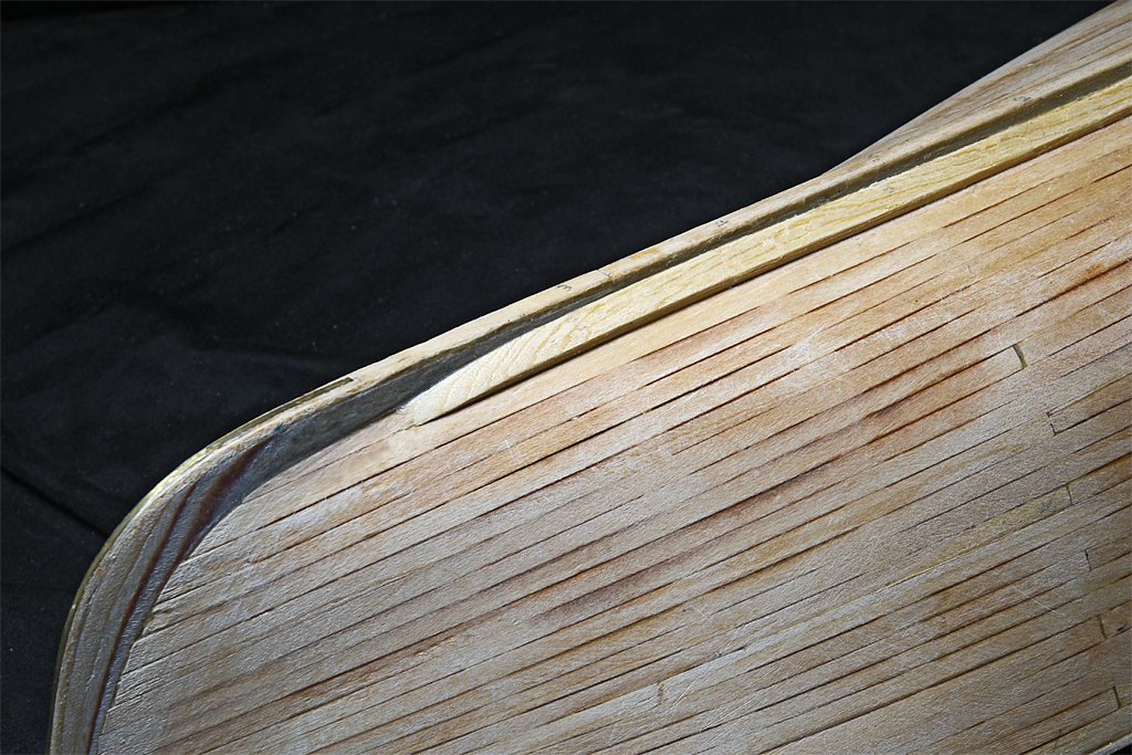
The ship had a "guard" or rub rail around the edge of the hull at the main deck level. This was even more complex in cross section than the garboard strake. The sections of the blueprints on the left below give an idea how the shape changed along the length of then hull. The drawing on the right below shows how I plan to create the guard. The red lines in the right hand drawing show the guard at several bulkhead positions. The top of the guard is flush with the sub deck, continuing the camber of the deck. The outboard side of the guard is vertical, and about 0.1 inch (2.54 mm) high along most of the length. The inboard side follows the line of the hull planking for a distance of 0.15 inches (3.8 mm).The bottom of the guard angles up from the hull planking to the bottom of the outboard edge. I gave some thought to trying to pre-shape a 0.25 x 0.25 inch (6.35 x 6.35 mm) strip before gluing it to the hull, but that would be pretty tricky with all the changing angles. Then I thought about trying to bend and twist a 0.25 x 0.25 inch (6.35 x 6.35 mm) strip around the hull edge but I wasn't confident about trying to bend a piece that thick without breaking it. I decided to build up the guard with two or three 1/16 inch (1.59 mm) thick strips. These could be shaped to fit the curvature of the hull easily using wet heat. In the image above right the outlines of these strips are shown in green. Where the hull angles outward near the bow I needed a 1/4 inch (6.35 mm) wide strip against the hull planking. Farther aft where the hull side is nearly vertical a 0.18 inch (4.6 mm) wide strip would do - this is the same as the hull planking strips. Near the bow and stern I may need three layers of strips to have enough wood for the guards. I used large rubber bands to hold the strips against the hull while gluing them. Metal pins were placed along a line 0.15 inch below the subdeck edge to fix the position of the strips vertically. The first layer of the strips rose above the edge of the subdeck, and the rubber bands tended to pull the top of the strips over and cause them to pull away from the hull at the bottom. I put some wood blocks on the subdeck under the rubber bands to change the pull angle on the guard strips. I put another set of short wood strips between the rubber bands and the guard strip along the lower edge of the guard strip to force it back against the hull planking. This worked nicely to hold the guard strip against the hull while the glue set. The first layer of the guard strips was the most challenging. After the glue had set the raised edge of the first layer gave a place for clamps to hold the second layer in place. The second layer was easier, but where the hull angled outward it was still necessary to use the short wood pieces between the rubber bands and the lower edge of the strips to hold the guard strip tight against the first layer. Here is the hull with two layers of strips in place for the guard. I am going to recalculate the dimensions again to see if the third layer is necessary. It will be needed for only a very thin extra width to the outboard edges in some places, and I may just build this up with wood shavings. The guard will be shaped in three steps. First the top edges will be planed, filed and sanded to continue the camber of the subdeck. Then the width outboard will be marked and trimmed to the correct thickness, with the outboard edge shaped vertical. The final step will be to mark the lower corner of the outboard edge and cut away wood on the lower side to create the angle down to the bottom of the guard at the hull planking. That will be the tricky and time consuming part of the job.

- 464 replies
-
- 9
-
-
- minesweeper
- Cape
- (and 1 more)
-
Nice plans George! When you look at a full rigged model you see lots of lines going here and yeah, it looks pretty busy. But when you really study the rigging it is amazing how many lines actually converge on the mast tops!
-
Artesania Latina makes several "micro shapers" draw plates for wood.
-
I have been working on a topsail schooner model, and in the process I have learned a lot about schooner rigging. Here is a link to where rigging the model starts. https://modelshipworld.com/topic/19611-albatros-by-dr-pr-mantua-scale-148-revenue-cutter-kitbash-about-1815/?do=findComment&comment=1007247 I have also posted a thread about rigging and sails on topsail schooners: https://modelshipworld.com/topic/25679-topsail-schooner-sail-plans-and-rigging/?do=findComment&comment=750865 There is a lot of information in the schooner rigging thread! A version of this is also included in the NRG Journal Winter 2024 - Vol. 69, No.4.
-
Paint it. Don't paint it. Paint it. Don't paint it. Paint it. Don't paint it. Paint it. Don't paint it. ... But what about the dollhouse?
-
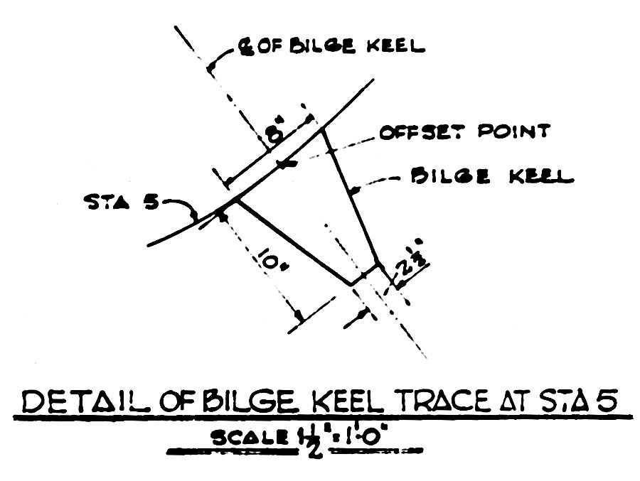
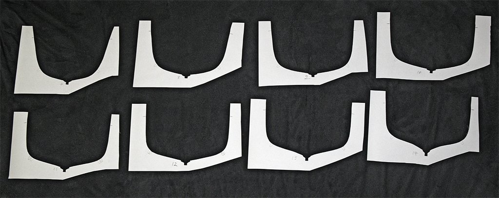
Tom, This was the first time I have put bilge keels on a model. I have seen drawings like the Booklet of General Plans for many vessels and wondered how to translate the 2D hull profile drawing into 3D positions on a hull. Likewise, the fore/aft drawings often show the bilge keels as more or less straight lines around the curvature of the hull (like great circles), but I couldn't decide how to turn this 2D information into 3D curves. It was a puzzle! So I would like to weave another long-winded tale (this is getting long) about the trials and tribulations of bilge keel design, but that would be BS! This is from the MSI Lines and Offsets blueprint. All I had to do is scale it to 1:48. And the 3D curvature on the hull? Just follow the instructions in the Table of Offsets - go to the frame number and get the height from the baseline and distance outboard from the center line and you have an offset point on the hull for the centerline of the bilge keel. That is what the paper bulkhead cutouts were for. Or, if you want, it was an arduous process full of missteps and endless rambling ...
- 464 replies
-
- 3
-
-
- minesweeper
- Cape
- (and 1 more)
-
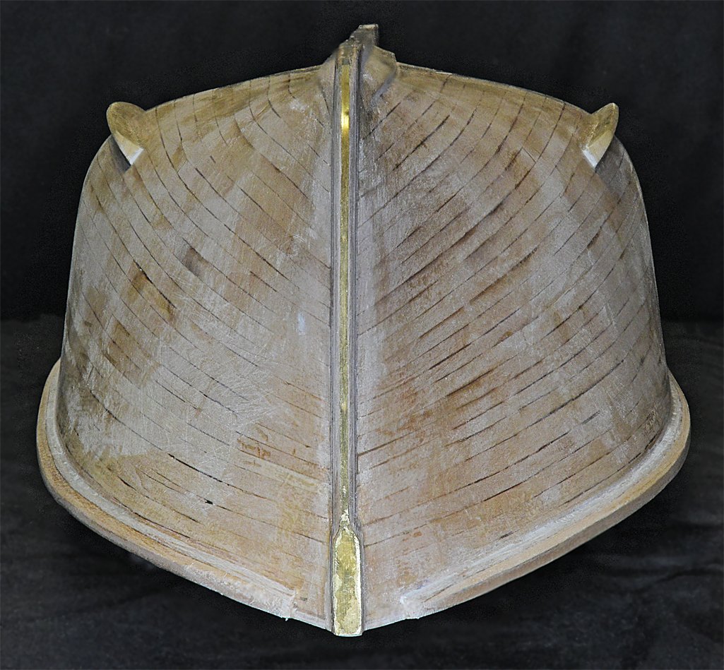
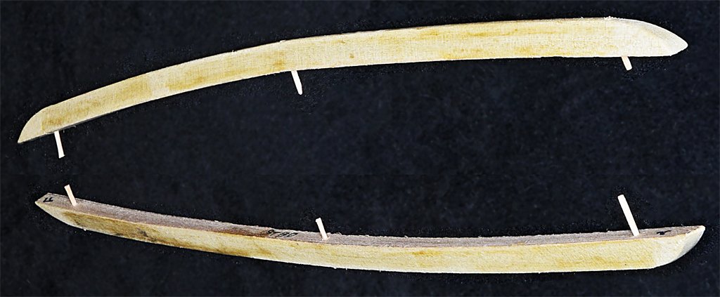
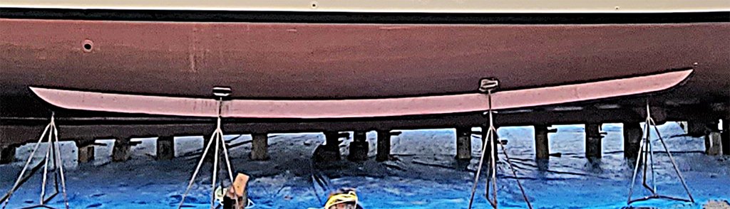
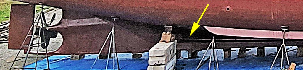
I have bilge keels. It took a while to figure out how to make these. Part of the delay for a few days was an annoying head cold. I made some paper templates using the drawings for the bulkheads with the keel positions marked on them. I placed each template over the keel at the corresponding bulkhead and marked the bilge keel positions on the hull. I used the Table of Offsets to get the positions of the bilge keels. Oddly, two of the dimensions (bulkheads 11 and 12) were inaccurate. But the remaining positions lined up perfectly. I have seen errors in the Table of Offsets for other ships so I wasn't too surprised. The cross section of the bilge keels is a trapezoid (truncated isosceles triangle) with sides angled 15 degrees from the base and a height of 0.208 inches (5.28 mm). I cut them from a 1/4 x 1/4 inch (6.35 x 6.35 mm) dowel from a local hardware store. The wood has no grain and sanded/filed/carved easily. If I had a milling machine the setup would have been trivial - but I don't have one. I figured out how to hold the dowel with some alligator clips and set the table on my disk sander to 15 degrees. I used this for the rough cut and finished it with sandpaper lying flat on the work bench. The pieces were temporarily fastened to the hull in approximately the right positions with large rubber bands. Then I used the wetting/heating process to bend the sticks. Even though I was bending across the wide dimension the wood bent to shape fairly quickly. Next I shaped the ends of the keels, using the photo above provided by Austin Cox. The blueprints do not show the overall shape of the bilge keels in any detail. I drilled 0.041 inch (1.04 mm) holes near the ends and at the center Then I held the keels to the hull in the correct position and used the holes as templates for drilling holes into the hull planking. I made six small pins by filing and sanding a bamboo skewer until it just fit into the holes in the keels. These "pins" assured that the keels would be properly aligned while I was gluing them onto the hull. It worked perfectly! The keels matched the curvature of the hull almost perfectly after gluing. At the ends there were slight gaps of 0.010 to 0.015 inch (0.254 to 0.381 mm) between the hull planks and the ends of the keels. I filled the gaps with Squadron White Putty.
- 464 replies
-
- 10
-
-
-
- minesweeper
- Cape
- (and 1 more)
-
One other consideration is that the upper yard might not be permanently mounted on the mast. It was a common practice on topsail schooners to rig the topgallant yard with the sail and rigging on deck and then hoist it to the top when needed. At other times the yard was not raised on the mast. This practice allowed most of the work to be done on deck by a small crew and didn't require a lot of sailors to go aloft. The sail could be hoisted up and hauled down quickly. I also learned that this practice was used on some large square rig ships for the royal yards. Somewhere I found photos of a royal yard and sail being raised on a clipper ship.
-
cutting, feeding, fixing model ship rope
Dr PR replied to palmerit's topic in Masting, rigging and sails
If you are having trouble pushing a rope through a hole, either the rope is too big or the hole is too small. Side cutters are essential for cutting rope very close to something. The blades are beveled on one side only and the cutting surface is smooth when the jaws are closed. -
Sandpaper Grit
Dr PR replied to Malazan's topic in Painting, finishing and weathering products and techniques
I want to second what Vaddoc said about coarse grit sandpaper leaving deep groves that will take a LOT of sanding with fine grit sandpaper to eliminate the scratches! And Vossewulf is right on about scrapers - although they don't have to be a fancy and specialized as his tools. Virtually any knife blade will work if you drag it along perpendicular to the surface. I use older "dull" blades for scraping. Curved blades are very useful for removing high spots in the planking and shaping concave contours in hulls. I use #0000 steel wool for final finishing when I need a glossy surface. But be sure to remove all tiny fragments before sealing and painting the surface. Tiny bits of steel wool embedded in the wood can rust over time and stain the wood. I have never had this happen, but I do clean the surfaces carefully. -
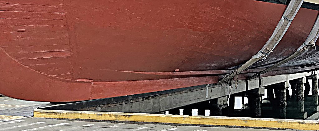
Austin, Thanks. I think we are up to date on emails. I sent some propeller information. Your photos are invaluable! They have simplified some of the problems in deciphering the blueprints. For example, I am planning the bilge keels right now, and your photos show the shape of the ends. The blueprints aren't very clear about that, but they do give the cross-section dimensions. Hope you have a good holiday and a healthy puppy!
- 464 replies
-
- 3
-
-
- minesweeper
- Cape
- (and 1 more)
-
George, Excellent research! Here are some comments about the questions you ask. 1. I made the partner covers from plywood. As you noted carving them out of wood will be tricky because you know they will break in half just as you are adding the final touches. The plywood has better strength than plain wood. https://modelshipworld.com/topic/19611-albatros-by-dr-pr-mantua-scale-148-revenue-cutter-kitbash-about-1815/?do=findComment&comment=911535 2. Having the pin rail perpendicular to the mast seems reasonable to me. 3. The cross trees look good. I would use the two aft most as as you did. 4. "Hounds" is a multiple meaning term, almost arbitrary. The area below the trestletrees is referred to as the hounds. However, I have seen one reference that said the hounds were additional pieces applied to the sides of the mast, and sometimes extending down 1/3 the length of the mast above the partners. Some authors call the cheeks the hounds. So the meaning of "hounds" and the length of the hounds is entirely arbitrary, and varies from vessel to vessel. It is essentially anything below the mast top. This is all and good until an author starts talking about the "hounded length" of a mast - the length from the foot/heel of the mast to the hounds. Many of the calculations for mast properties are based upon hounded length. But what part of the hounds? To the top, the bottom or somewhere else? To the top of the trestletrees or the bottom? Rarely does and author tell. We are supposed to already know the "right" answer, or to read their minds. Harold Underhill (Masting and Rigging the Clipper Ship and Ocean Carrier, Brown Son and Ferguson, Ltd., Glasgow, 1972, page 5, Figure 4) is the only author I have found who gives a definite answer to what hounded length refers to, and he shows the hounds as the bottom of the trestletrees for determining hounded length. Harold Underhill does give a definition of "hounds" in Sailing Ship Rigs and Rigging (Brown Son and Ferguson, Ltd., Glasgow, 1969, page 110): Hounds - A change in the diameter of the mast to form a rest for the eyes of the rigging, crosstrees, etc. So now we know! In any case I think you have done your homework and can justify the decisions you are making for your model.
-
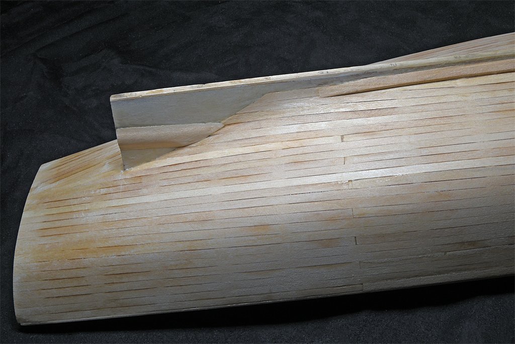
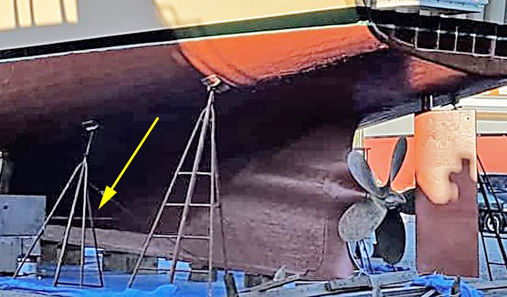
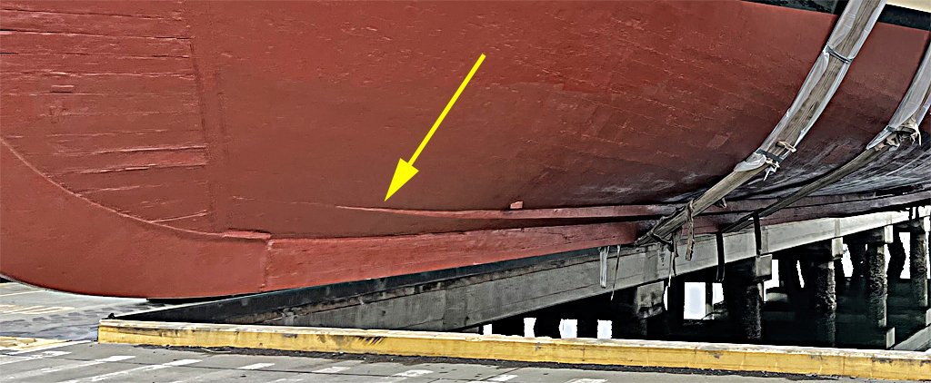
After "completing" the garboard strake I was looking at the photos of the current day Cape and realized I did not carry the strake forward enough. I was going by the blueprints, and they don't show the strake extending forward of frame 7, just forward of my bulkhead 2. But the photo (below) clearly shows the strake running forward to where the planking is starting to turn up at the stem. I should have been paying more attention to the photos! I cut off the most tapered part of the strake (left below) and added a new piece to extend the strake forward to just past my bulkhead 1 (right below). This is closer to what is on the real vessel. Maybe not perfect, but good enough. I have also started working on the bilge keels, but that is a story for another post.
- 464 replies
-
- 9
-
-
- minesweeper
- Cape
- (and 1 more)
-
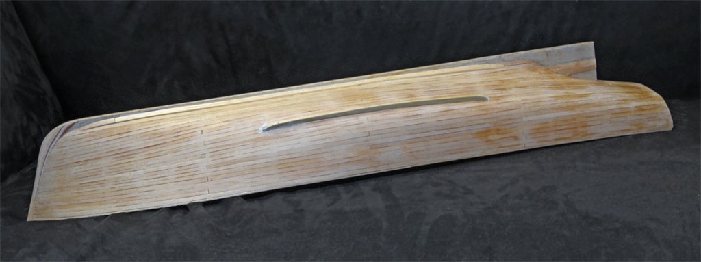
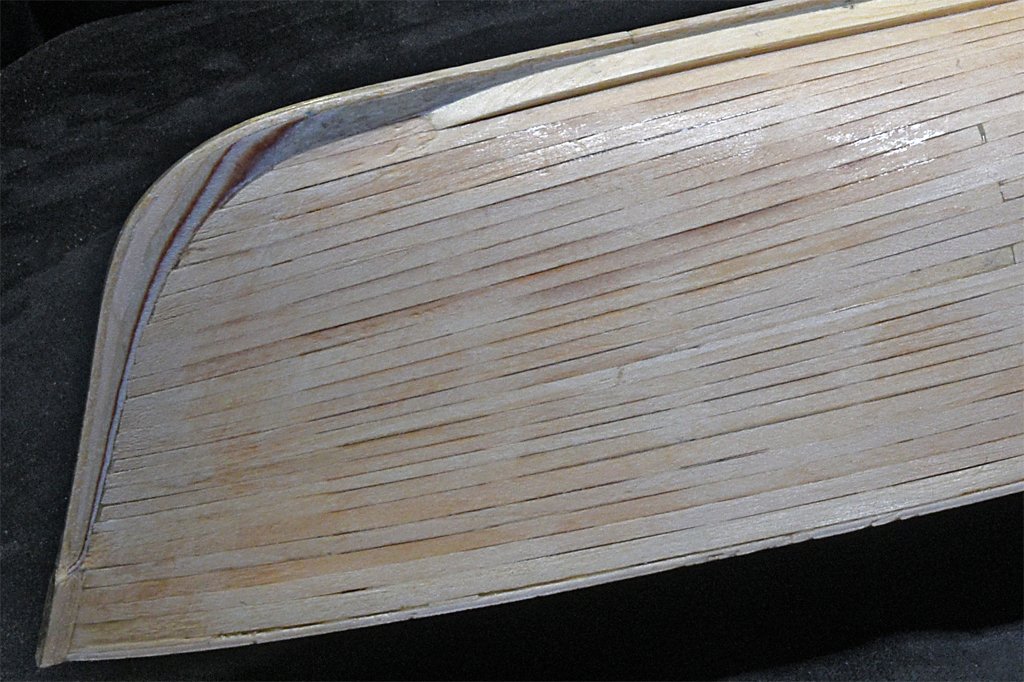
The garboard strakes are finished - well, I may do a bit of retouching before I paint the hull. I may taper the front and rear ends a bit more. These "planks" had to be about 0.080 inch (2 mm) thick, so I couldn't use any of the 1/16 inch (1.59 mm) planks. I started with a 1/4 x 1/8 inch (6.35 x 3.175 mm) basswood stick and shaved it down to 0.080 inch with a plane. Then I used wet heat to bend it into the shape of the hull. I used a file and sanding blocks to make the angled edges and shape the piece to fit in the angle between the hull planking and the keel. Next will be the bilge keels, and then the "guards" (rub rails) around the edge of the deck.
- 464 replies
-
- 8
-
-
- minesweeper
- Cape
- (and 1 more)
-
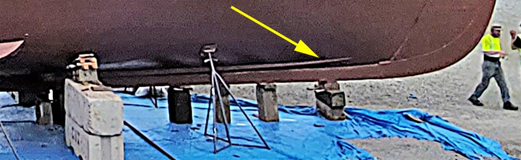
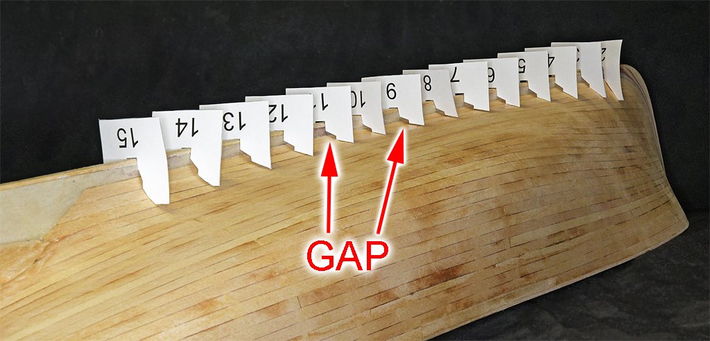
Another of the hull details to be completed is the garboard strake. I have installed the first layer flush with the other hull planks. Now I need to add the second layer that is built up on top of the first layer. The blueprints do not show the details of this strake clearly. However, thanks to photos from Austin Cox (the current owner of the Cape) of the vessel on blocks I can see what the strake looks like and where it ends. As you can see in these pictures the strake tapers down to match the contour of the other hull plating just aft of where the stem starts to curve upward, This is about bulkhead 2 on my model. The taper at the aft end is a bit harder to see. It is clear that the strake tapers down to the contour of the hull planking a bit forward of where the planks fair into the deadwood, forward of the stern frame and propeller. This is just aft of bulkhead 15 on the model. To help visualize the shape of the strake I made a series of paper templates from the drawings of the bulkheads. You can see the gaps in the templates where the keel and planking come together. These show the shape of the garboard strake. I think the strake can be carved from a 1/4 x 1/8 inch (6.35 x 3.175 mm) basswood stick. I will cut the angle at the corner between the keel and planking first. This will be on the "inside" with the glue where it won't be visible so the angle doesn't have to be precise. Then I will use heat to curve the plank to the shape of the hull. After that I will use the templates with files and sandpaper to shape the exterior surfaces. At least that is the plan. We'll see what Murphy has to say about it!
- 464 replies
-
- 12
-
-
-
- minesweeper
- Cape
- (and 1 more)
-
I am putting reef points on the sails of my schooner build. https://modelshipworld.com/topic/19611-albatros-by-dr-pr-mantua-scale-148-revenue-cutter-kitbash-about-1815/?do=findComment&comment=1073721 The ends are just wherever they fell when I was adding the points. They are held down with dilute (50:50 with water) white glue. After the sails are installed I will use a paint brush with water to reposition the ends so they hang down "naturally." I have posted quite a bit of information about how sails are made starting at this link: https://modelshipworld.com/topic/19611-albatros-by-dr-pr-mantua-scale-148-revenue-cutter-kitbash-about-1815/?do=findComment&comment=1035898
-
Hmm ... An 0-5-0. Unusual!
-
Ships flew pennants or flags from the mast tops and these told the direction of the wind.