
HOLIDAY DONATION DRIVE - SUPPORT MSW - DO YOUR PART TO KEEP THIS GREAT FORUM GOING! (83 donations so far out of 49,000 members - C'mon guys!)
×


Dr PR
-
Posts
2,438 -
Joined
-
Last visited
Content Type
Profiles
Forums
Gallery
Events
Everything posted by Dr PR
-
 Mark, That beam definitely needs to be raised to meet the level of the other bulkheads. I have had this happen with kits too. Perhaps the bulkhead is a bit too low. If so you might see some problems with hull planks around the turn of the bilge. It looks like the low spot is just aft of the main mast. Maybe there are structural pieces to frame the mast opening (partners) that rest on this bulkhead. On my Albatross build I had to add shims to the tops of several bulkheads to get a fair line for the deck. You may also need to shave a bit off the tops of other bulkheads to get a good lay of the deck. **** When bending planks it is best to heat the planks to make the bending go faster. I use a small quilting/plank bending/sail making iron and usually bend the planks in situ on the hull. to get the proper curves and twists in the planks. https://modelshipworld.com/topic/37060-uss-cape-msi-2-by-dr-pr-148-inshore-minesweeper/?do=findComment&comment=1074225 https://modelshipworld.com/topic/37060-uss-cape-msi-2-by-dr-pr-148-inshore-minesweeper/?do=findComment&comment=1075263
 -
Mike, For future reference for deck plank grout see these links: https://modelshipworld.com/topic/19611-albatros-by-dr-pr-mantua-scale-148-revenue-cutter-kitbash-about-1815/?do=findComment&comment=602855 https://modelshipworld.com/topic/19611-albatros-by-dr-pr-mantua-scale-148-revenue-cutter-kitbash-about-1815/?do=findComment&comment=605072 I have also seen planking tests on some other threads on the Forum.
-
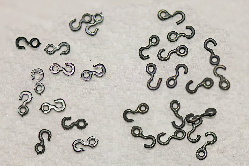
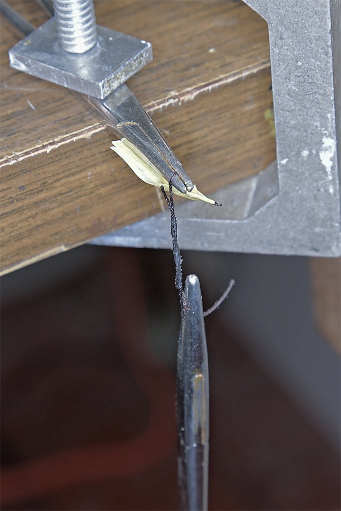
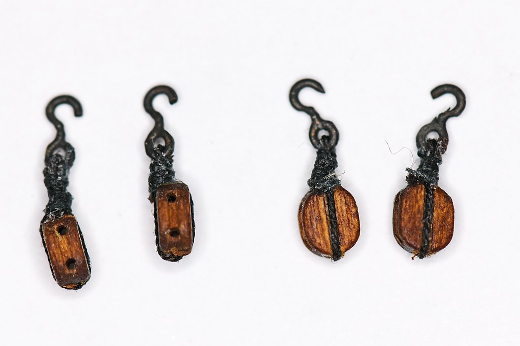
I use chain nose pliers (round node pliers) to start the loop and hook, and then to finish to a desired size I use ordinary needle nose pliers to tighten them around the shank of an appropriate size drill bit clamped into a vise. I do the same to make eye bolts and such. While holding the loop closed with the pliers I give the wire a tug to make a sharp bend at the loop where the shaft of the eye bolt or hook leads away from the loop. I do recall seeing someone with several chain nose pliers of different tip diameter to make different sized loops. I use K&S brass rod instead of ordinary brass or copper wire. The rod is hardened and much stiffer. It makes sturdier hooks and eye bolts. A friend who makes model railroad scenery kits showed me how to straighten and harden ordinary brass wire by clamping one end in a vise and giving the other end a hard jerk. It works, but I still prefer the brass rod. I think I have seen someone using piano wire, but it is very hard and stiff, and harder to work than the brass rod. I finish the loop by soldering - I originally left the loop end unsoldered, but really fine rope and thread sometimes managed to slip through the gap (with Murphy's help). I use a citrus based liquid flux (I like the orange smell), placing a small drop at the wire end. I have a soldering iron with a small tip. I place a small drop of solder on the tip and touch it to the joint. The liquid flux draws the solder into the joint. Sometimes I have too much flux or solder and the solder flows into the loop on the hook. I do have some woven copper solder remover - or you can use ordinary multistrand wire - to remove the excess solder. But I usually just clean the soldering iron tip (on a wet sponge) and then put the tip into the loop and draw the solder back down the shaft of eye bolts. For hooks I use a small diameter drill bit to drill out the solder from the loop. After the soldering and shaping is done I use Birchwood Casey Brass Black to blacken the hooks and eye bolts. Here are some of my home-made hooks on the right, and Syren 4 mm plastic hooks on the left. My metal hooks are stronger, but I have not mastered the technique enough to get consistent hook sizes. For more consistent results I think I need to make jigs of several sizes that the hooks can be wrapped around. I also haven't worked out a way to get the mousing tip on the hook. Steve seems to have figured that out. I'll have to practice a bit more. On real hooks the mousing end is tapered to a point, but I think that is a bit more detail than I want to attempt on these tiny hooks.
-
Your problem is obvious - you have an Apple product. They seem to make an effort to be incompatible with everything else. If you have Windows (you mentioned Microsoft) you can use the Print Screen key ("prt sc" or something similar) to capture an image on the screen. Then use the Microsoft Paint program (supplied with windows) and paste the saved screen image. You can edit the picture to change size, crop and such. Then save the picture as a JPG file. This will work with the Forum and virtually every other program..
-
1/8 inch blocks small? Try working with 3/32 inch (0.083 inch, 2.4 mm)! You did a nice job on the gun tackles! Did you make the hooks yourself?
-
Steve, I have been using Duco or something like it since I was a kid (1950s). It soaks into and adheres to anything that is porous. In the test I used a metal point to work the glue in between the rope strands. But I think it is fluid enough to soak in on its own. The polyester rope tends to unravel after it is cut. I always stick the freshly cut ends into the opening of the Duco cement tube to get a drop on the rope end. Then I twist the rope end between my fingers and the glue soaks in. When it dries (a few seconds) the end of the rope is stiff enough to push through holes in blocks and such. Even though I wipe my fingers immediately on a paper towel, I do go around with dried glue in my fingerprints! But unlike CA it wears off quickly. Duco does leave a dried film on anything it touches. In the case of the ropes it isn't noticeable because the surface isn't smooth. But if you look closely with a magnifier you might be able to see traces of the glue. Where it soaks into wood surfaces it can change how stains appear so use it sparingly. For most wood to wood jobs I use Sig-Bond aliphatic resin. I think Titebond is about the same.
-
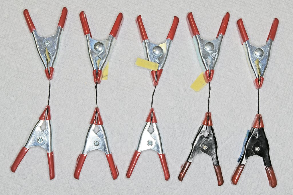
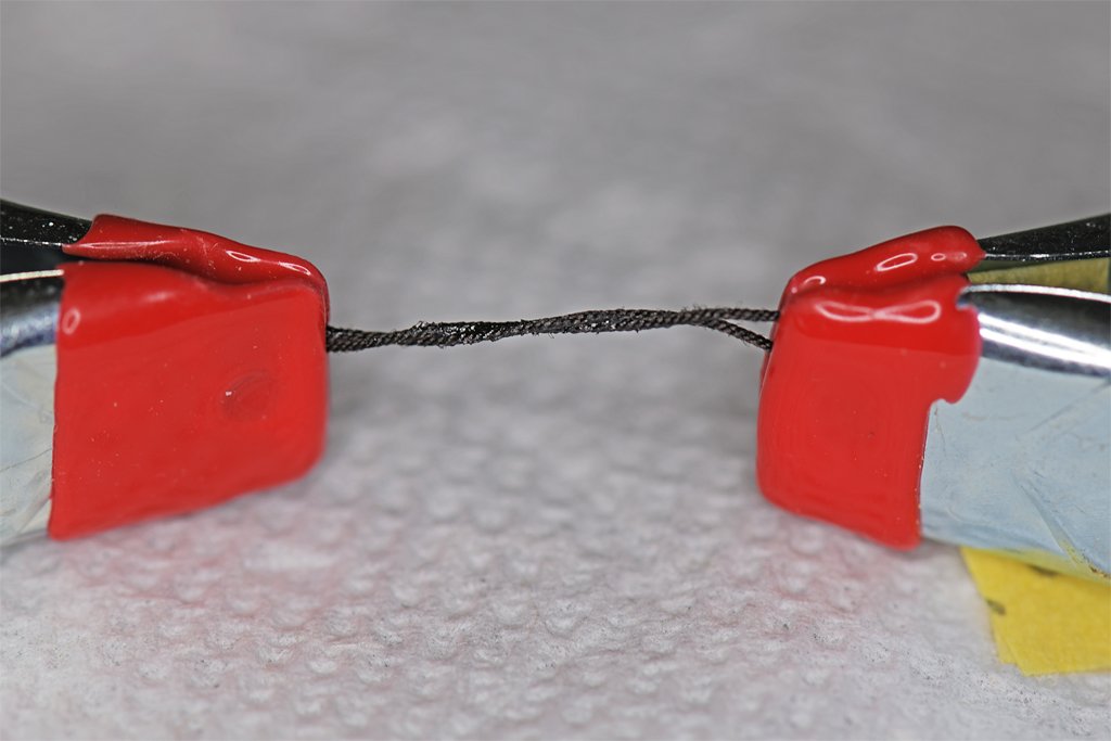
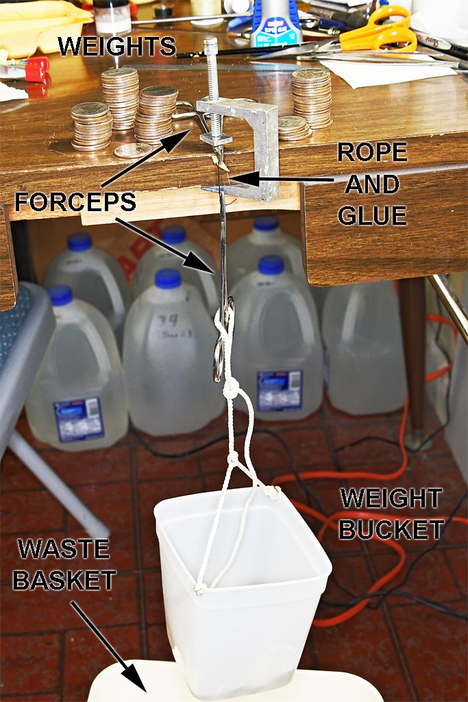
I decided to test several "glues" to see which was best for bonding polyester rope. I used Syren Ultra Brown 0.018 inch (0.45 mm)scale rope in these tests. It is a medium size rope that provides a good surface area and volume to test the adhesives. The "glues" were: White glue - Office Works acid free school glue. It was used full strength, undiluted. Sig-Bond - an aliphatic resin. Duco Cement - an acetone solution of nitrocellulose. Loctite Super Glue Gel Control - cyanoacrylate (CA). Zinsser Bulls Eye Shellac - from spray can. I sprayed into a small bottle and then painted the shellac onto the rope with a brush. I twisted two strands of rope together and clamped both ends. Then a liberal amount of the adhesive was painted onto the strands. I used a metal needle to work the liquid between the two rope strands. Then the rope was pulled tight and twisted to keep the strands together while the glue dried. After the glues had set for 12 hours I clamped the ends of each strand with forceps. One of the forceps was clamped to the edge of the work table. On the other forceps a line was looped around the handles and the other end of the line was attached to a plastic bucket hanging above a small waste basket. The waste basket was there to catch the quarters when the bucket fell - they tend to "splash" out of the bucket when it lands. I have a box full of US quarters (25 cent pieces) for spare change. Quarters weigh 0.2 ounces or 5.6 grams. These were my test weights. With the bucket suspended from the lower forceps I added quarters to the bucket until the weight was enough to break the glue bond. Or that was the plan. Here are the results. Shellac - 0 g - The rope strands separated before I got them clamped into the forceps. White glue - 1187 g - With 2 lb. 9.9 oz. pull the cement failed. Sig-Bond - >2080 g - With 4 lb. 9.3 oz. pull the rope unravelled and pulled from the forceps before the glue bond failed. * Duco Cement - 2196 g - The glue bond failed with 4 lb. 13.5 oz. pull. Super Glue - 1410 g - the rope broke with only 3 lb. 1.7 oz. pull before the glue bond failed. The rope strands were tightly glued together but I could pull them apart by hand. * * The Sig-Bond and Super Glue failures were due to experimental design. When the rope was clamped in the forceps it tended to unwind. With the Sig-Bond the unwound strands pulled out of the forceps. With the Super Glue the strands frayed and cut along the edge of the forceps jaws. To do the experiment properly some means must be developed for holding the ends of the rope strands securely without damaging the rope. It is clear that shellac alone does not bond the rope strands together. It does serve to stiffen the rope. White glue was easily the weakest of the four glues. Sig-Bond produced a strong attachment between the rope strands, but it dried with a thick off-white crust on the ropes. Duco Cement and the Super Glue did not leave a noticeable residue on the ropes and both were better than white glue. Duco smells like acetone - it is the familiar "glue" smell from my childhood, and I don't find it objectionable. So little is used it isn't a hazard. Super Glue has an odor that really bothers some people. It makes my eyes burn if I use it a lot. I think I will use the Duco Cement from now on. Duco starts getting sticky in 20-30 seconds and sets in a minute or so, leaving plenty of time to tidy up a seizing. Even the "slow" Superglue gel starts to harden before I have time to finish the turns in a seizing, without reworking them, leaving a lumpy seizing.
-
Before you put a lot of planks on the hull clamp one on each side at the top of the bulkheads. Look at it from straight on bow and stern and see if both sides have symmetric curvature. I see a fair number of models that have wavy or asymmetrical curvature to the cap rails on the bulwarks because this last check wasn't performed before starting the planking. Your measurements and sanding probably will be enough, but it doesn't hurt to make this last check. This is a last chance to get it right.
-
Thanks for the comments. I was hoping to avoid using CA. It makes my eyes water and burn. I don't know if adding the CA over the white glue will do any good. I doubt it will penetrate the white glue on the seizing. It isn't the white glue on the seizing that is failing - the seizing is still intact, leaving a nice hollow tube of tightly wound thread. The CA really needs to be applied directly to the polyester rope inside the seizing.
-
228 mm (9 inches) might not be too wide for deck planks. I have seen references to vessels with wide deck planks. However all the vessels I have been on have had deck planks closer to the 114 mm (4.5 inches). Splitting the 4 mm planks will be tricky. When you start to split wood the split tends to follow the wood grain. Unless the planks were cut exactly parallel to the wood grain you will get a lot of scrap wood. You can buy 2 mm planks from model lumber supply companies. I don't recall either Chapelle or Marquardt discussing what the deck plank width was. However, there are some lists of materials that were purchased for specific vessels that might give the deck plank dimensions. For example, Chapelle's The Baltimore Clipper on page 168 lists material for H.M. schooner Spider of 1815 that says deck planks were 7 inches wide.
-
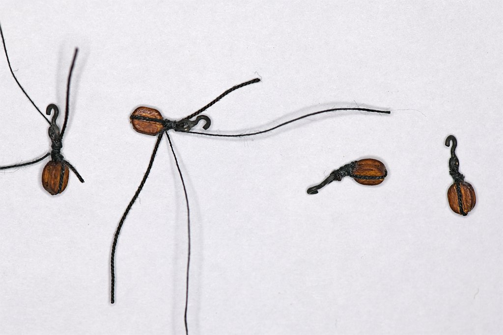
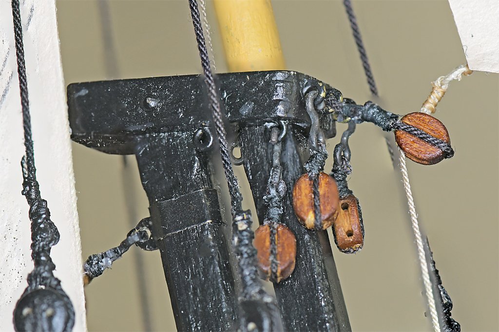
I have some "progress" to report - more like two steps backward and two forward! I few posts back I griped about it taking an hour each to attach two lines (main topmast staysail halliard and sheet) to belaying pins on the fife rail in front of the main mast. Well, while planning the rigging for the fore course braces I noticed that I had wrapped the main topmast staysail halliard around another line! So It has to be redone! That's one step backwards! Then while I was starting the rigging for one of the braces the seizing on one of the blocks at the main top failed and the eye opened, allowing the block to fall off the mast. Another step backwards. I have been having too many problems with the seizings failing and allowing eyes to open that fastened ropes around hooks, blocks, spars and such. THE PROBLEM IS THAT WHITE GLUE DOES NOT STICK TO POLYESTER ROPES. To make the eyes I have been looping the short end of a rope back on the long end and clamping the two strands. Then I used thin (0.003 inch, 0.08 mm) silk or cotton thread to tie an overhand knot around the two rope strands where I wanted the seizing to start. One end of the knotted thread was taped to a clamp to keep it out of the way. I put a drop of diluted (1:1 with water) white glue on the knot and the two strands of rope. Then I looped the long end of the thread around the two rope strands 6-8 times, using the seizings to close the eye down to the desired size. These turns were also wetted with diluted white glue. Then I tied a final overhand knot to finish the seizing. While the glue was still damp I used tweezers to push the seizing coils together tightly, and then tugged on both ends of the seizing thread to tighten the coils around the rope strands. When the glue dried the eye looked quite strong - and is strong enough for lines that have no stress on them. But just the force of pulling loose ropes through blocks was enough to cause the short end of the rope to pull through the seizing, opening the eye and leaving a perfectly formed seizing on the long end of the rope! I have had half a dozen of these seizings fail, especially when I accidentally bumped a line or spar while working in the rigging. The sudden force on the ropes just opens up the eyes as if there was no glue at all! I have resorted to placing a small drop of super glue (cyanoacrylate) gel on the two rope strands after tying the first knot to pull the strands together. Then I have to wrap the seizing rapidly before the glue gel hardens. But the superglue becomes very sticky rapidly and it is hard to finish the loops and tie the second knot before it hardens. I cannot push the coils of the seizing together or pull on the ends of the thread to tighten the seizing into a neat finished shape. But it appears the super glue does bind the two rope strands together, and it sticks to the seizing as well. Here are some repaired seizings. On the left are two block and hook assemblies after tying and two more after the ropes and threads have been trimmed. On the right is a close up of these assemblies showing the rather lumpy seizings created with superglue. One step forward. I have also had a lot of the Syren plastic hooks fail. I think one problem is that you can twist them as you are trying to hook onto eyebolts inside a bunch of rigging lines and other obstructing objects. This can cause the opening in the hook to be stretched, cracking the plastic. Sometimes the hook breaks immediately. But often it is when I am pulling rigging through the blocks the hook breaks, or if I bump a line or spar. Of course it always will be a hook that is buried behind a lot of other lines where it is near impossible to reach! Another step back! My solution is to make metal hooks from hard brass wire, and solder the eye loops closed so lines cannot squeeze between the wire ends. Then I blacken them with Birchwood Casey Brass Black. I cannot make hooks as uniformly sized or pretty as the Syren hooks, but they are a LOT stronger. The hooks on the blocks in the pictures above are my metal hooks. Another step forward! Here are several of my superglued metal hook and block assemblies hanging from eye bolts on the main mast top. The lower aft (port and starboard) are for the main course brace lines, and the two on the face of the top outboard (port and starboard) are for the fore topsail yard braces. Now I can proceed with rigging these lines with confidence these seizings will not come undone nor the hooks break! The center block is attached to an eyebolt with a white glued seized eye. And the seizing around the eye of the staysail sheet is another white glued seizing. Neither failed while I was rigging the main topmast staysail sheet. But I have to be very careful to not place any stress on this line!
-
Peter, Thanks for the measurements. They are close to what I got from one of Chapelle's drawings. And it dpes seem to confirm that the foremast had a greater rake than the main mast. Mark, I like what you have done for the stern counter, but I agree with Peter that you might not have enough room for the rudder post. You can do two things: 1. If you are confident about your deck measurements and overall length of the hull you can carve off a bit from the rear of the false keel/center piece to move the rudder post forward sufficiently. Note: The "length between perpendiculars" that is often used to measure hull length of wooden sailing vessels is from where the front of the bow cuts the water at the normal load waterline (Fore Peak) to the normal load waterline at the center of the rudder post (After Peak). If you have this dimension for the Lynx you can check where your rudder post should be. 2. Or you can remove the transom, extend the framing a bit and reinstall the transom. Before you start any planking on the hull or the deck I advise you to check the side-to-side (transverse) dimensions from the center line to the outside of the frames, especially at the stern. On my schooner build (started in the 1980s) I somehow got the distances port and starboard at the stern unequal by a bit. When I was planking the deck and came to the part for nibbing the planks into the margin board/waterways a few years ago I discovered the mistake. That left me scratching my head for a solution. Fortunately I was able to cut the nibs into the margin board a little deeper on one side so the ends of the planks were aligned on both sides. Unless you know to look you would never notice the difference - especially now that a lot of this area is covered with the boom, sails and rigging. But it is a good idea to stop, take a deep breath and recheck all of the dimensions before planking. You can always make corrections by sanding off a bit from the outsides of the bulkheads before starting the planking. After you have installed the planking it is too late.
-
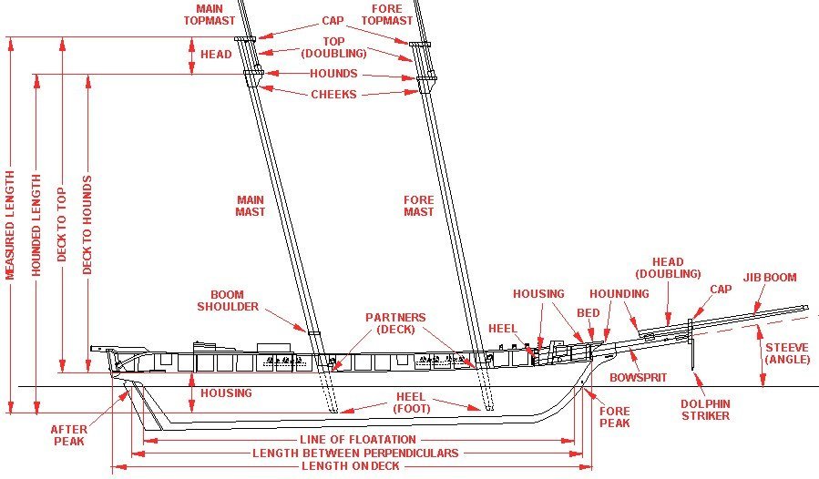
Trevor is right about the instability of the heavily rigged American topsail schooners. The British originally had more conservative rigs, but the American vessels could just run away from them to avoid a fight. When the Brits did start using the larger tophamper they learned just how dangerous it was. I think it was in one of Chapelle's books he repeated a British captains story of a topsail schooner that was passing his ship running with the wind in heavy seas. The schooner rode up on one swell, dove down bow first into the next, then cartwheeled stern over bow and dove out of sight in seconds taking all hands with it! I looked at Chapelle's drawings of the Lynx in "The Search For Speed Under Sail" and in both the hull drawing on page 217 and the sail plan on page 219 the fore mast rake was about 13 degrees and the main mast was about 14 degrees. The drawing says the vessel was built in Baltimore in 1812 and the lines were taken at Portsmouth, May 1816, and the plans are at the U.S. National Museum, Smithsonian Institution. These rake angles are common for Baltimore clippers, and usually the greater rake is on the main mast! If you look at the photo of the Lynx model at the U. S. National Museum on page 216 it looks as if the main mast has a bit greater rake than the fore mast. However, if you look at his drawings of the Musquidobit on pages 84 and 85 of "The Baltimore Clipper" the rake angles are 17 degrees for the fore mast and the main mast is 14 degrees! This "draught" is labeled as taken at Portsmouth Yard, May 1816!! Note: In both cases I measured the angle to the waterline marked on the drawings. But the hull plan "waterlines" are drawn parallel to the bottom of the keel. The keel had greater draft at the stern than at the bow. And to confuse things even more, in Chapelle's "History of the American Sailing Navy" Plate X after page 74 (a photo of an original sail plan drawing) shows an 80 foot schooner named Lynx with a foremast rake of 10 degrees and the main mast at 11 degrees. He says (page 292) this schooner was built in 1814 at Washington or Georgetown, and was lost in 1820 in the West Indies (page 354) while still in American service!! If you figure this one out let me know!
-
Close up (macro) photos always show little things that you don't see with the naked eye. Judge it by what it looks like without the camera! 1:64 is small enough that you can probably just cut off the pin heads and let just a short bit of the pin shaft show for the door handles. If you don't give anyone a magnifying glass to examine the model they will never know!
-
The problem with using a clip-on guide without having a template for guidance is that the spacing between lines can creep, especially on the ends. After a while the lines are not parallel to the water line, running high on one end or the other. I speak from experience! And that is why I always have a template that I can use for reference.
-
USS Constitution by mtbediz - 1:76
Dr PR replied to mtbediz's topic in - Build logs for subjects built 1751 - 1800
Mustafa, I thought your Pickle was an excellent build, but this one is a tour de force! -
John, Any build that is finished is a good build! Santa Maria is a good choice for your second build. It was my first kit build back in 1969 (long before the Internet and Forums like this). It is a bit more complicated than your first build, and you should learn a few more tricks. But the masts and rigging are not nearly as complicated a later ships, especially the huge full rigged behemoths of the 1700s and 1800s! So you will learn rigging skills without learning the frustration and sheer boredom of rigging your 50th cannon or yet another sail. There are many useful books for ship modelling - and a lot that weren't helpful at all to me. But if you are having trouble distinguishing between futtocks and carlings may I suggest you look online for Falconer's Universal Dictionary of the Marine (1769). You can copy it off the Internet. It describes a lot of the arcane nautical terminology us ship modelers throw around to make it sound like we know what we are talking about.
-
Digitalis (Foxglove?), A lot of experienced builders prefer Titebond II so it is OK. White glue (Elmer's Glue-All) is probably cheaper. When you get to the rigging stage you might want to set some. It's greatest advantage is that it dries invisible without leaving a film or stain. That may be why they recommend it. If you got plans off the web site you might look at them to see if there is a drawing sheet (or two). You can take the file to a print shop and have the sheets printed to scale. As far as the CD goes, the kit may have been manufactured years ago when CD/DVD players were common, and has been sitting on the shelf somewhere since then. Good luck on your build. Don't let the kit's shortcomings prevent you from doing your best. And you should know from the very beginning that you will make mistakes, and your second ship model build will be a lot better than your first!
- 47 replies
-
- 2
-

-
- La Nina
- Artesania Latina
- (and 1 more)
-
All right! Another schooner build!! You did a nice job on the planking.
-
Keith, I took one look at all the bead thingies on the bow decoration and wondered how you would carve them. Ball bearings! Great idea, and the resulting part is very nice!
-
This is how to make a ratline template and use it. 1. Measure the distance between the top of the deadeyes and the bottom of the trestletrees or crosstrees. 2. Cut a piece of paper to be this long on one side. 3. Put the paper behind your shrouds, with the bottom edge resting on the deadeyes. 4. Use a pencil to place a mark on the paper beside each of the shrouds at the top of the deadeyes. 5. Mark the top of the paper beside the forward and aft shroud lines. 6. Draw lines on the paper for the forward and aft shrouds. You really don't need lines for the other shrouds. 7. Now you have to think. Ratlines were typically spaced 12 to 16 inches (305 to 406 mm) apart. Now scale this distance to whatever scale your model is. For example, I am building at 1:48 scale, so I divide the real world distance by 48 to get 0.25 to 0.33 inches (6.35 to 8.5 mm) spacing for the ratlines on my model. Note: unless you are modelling a modern vessel there probably will be no record of the actual ratline spacing on the ship you are modelling, so pick a convenient spacing within the range you calculated. I will space them 5/16 inch (0.3125 inch) (7.9 mm) using a ruler marked in 1/16 inch increments.. 8. On your paper template draw horizontal lines parallel to the tops of the deadeyes at your chosen spacing. These mark where the ratlines will go. 9. Trim excess paper around your ratline template, leaving a narrow space outside the lines representing the fore and aft shrouds. 10. Tape the top of the template to the shrouds below the trestletrees/crosstrees. Clamp the bottom of the paper to the deadeyes. You could use tape, but you probably will want to release the bottom of the paper to get it out of your way while tying all the ratline knots. 11. Put on some soothing music, take a deep breath and don't even think about how many knots you will have to tie for just one set of shrouds! 12. Now tie ratlines at every level marked by horizontal lines on the template. Note: Some people clamp a small stick to the shrouds at the level of the ratline to be installed, using the template to set the position. Then they fold the template back out of the way and tie the knots above the stick. IMPORTANT! After all the knots are tied check the line against the template and move the knots as necessary to get the line in the correct position. Sloppy work here will make the model look BAD! It is a good idea to use a small brush to place a drop of diluted white glue (1:1 with water) on each knot as insurance to be sure the knot doesn't open or move on the ratline. The ratlines are tied with clove hitches (look it up). This brings the two ends out from the knot at the same level. Leave a slight "sag" in the line between shrouds - this takes some practice. You can make this sag permanent by wetting the line with diluted white glue or shellac (dries faster). On real ships the ends pf the ratline ropes had eyes spliced in them. The eyes were tied to the outer shrouds with small line. For all but the largest scale models this is unnecessary detail, and a LOT of extra work. I just use a simple overhand knot to tie the ratlines to the fore and aft shroud lines.
-
George, Agreed! On one of my earlier models I added the entire interior, including furniture, even though none of it was visible in the finished model. But I had the satisfaction of knowing it was there!
-
Wefalck, Douglas fir (Pseudotsuga menziesii) covered most of the western parts of British Columbia, Washington, Oregon and northern California west of the Cascade and Sierra Nevada mountain ranges. It was more abundant than grass (in acres covered). In the coastal rain forests trees grew to 15 feet (5 meters) diameter. The major industry was harvesting and exporting these trees to every large city from California to Alaska, and to Asia. Everything was made from Douglas fir, including ships (there isn't much iron ore on the west coast). When steam came along the hulls were still wooden. Likewise, when diesel came along they still built ships from wood. And timber harvesting is still a major industry even though most of the original forests have been harvested and replaced with plantations. In Oregon alone the land area growing timber (about 24 million acres) is greater than the entire area of many of our eastern States and some European countries! So yes, it is an abundant resource!
-
Looks like it might make a good small gear puller. I wonder if that is what it really was made for?
-
Whats the best book on rigging for a beginner?
Dr PR replied to Stuka's topic in Masting, rigging and sails
Keep in mind when people say "accurate" with respect to some rigging plan what is really meant is "I wonder if a ship was ever rigged this way." There was no "one way" for any type or rig, so it might be better to ask "Is there any reason why a ship might not have been rigged this way? Ships were not necessarily rigged just one way throughout the entire ship's life. There are many examples of ships that were re-rigged multiple times. So the "accurate" question becomes "When might the ship have been rigged this way." And the only real answer to any of these questions is "We don't know." Many plans for rigging a particular ship actually come from a model somewhere in a museum - Petersson used this method. But if you follow some of the threads on the Forum you will come across discussions of whether the model rigging is "accurate." Is it original, or has the model been "restored" changing the rigging from the original. Even restored "original" historic ships like the USS Constitution or HMS Victory have been restored several times, and there are always questions about whether the restored vessel is really "accurate." Do not get hung up on questions of "accuracy." We don't know for certain. So concentrate on "probable." Is it a reasonable way to rig a ship?


