HOLIDAY DONATION DRIVE - SUPPORT MSW - DO YOUR PART TO KEEP THIS GREAT FORUM GOING! (83 donations so far out of 49,000 members - C'mon guys!)
×


Dr PR
-
Posts
2,439 -
Joined
-
Last visited
Content Type
Profiles
Forums
Gallery
Events
Everything posted by Dr PR
-

scissors, shears, cutters for rigging
Dr PR replied to palmerit's topic in Modeling tools and Workshop Equipment
I have a small scissors that I got at a local sewing supply shop. They cut all the sizes or rope/thread that I use, and do cut all the way to the tip. But they are typical scissors with blade that slide past each other, and cannot be used to cut line ends very close to knots and such. I bought some cheap side cutters at Harbor Freight that cut very close to blocks and such, and cut to within 0.01 inch (0.254 mm) of the tip. However, you have to be careful selecting them. There were about two dozen in the store, and only two had jaws that closed together parallel so no light came through a crack. For extremely close cutting to clip off the ends of line at knots and such I have good set of cuticle cutters. They are very sharp and cut all the way to the tip. The jaws are made at an angle to the handles, reducing interference from the handles (and hands holding them). None of these tools were very expensive but they do the job. -
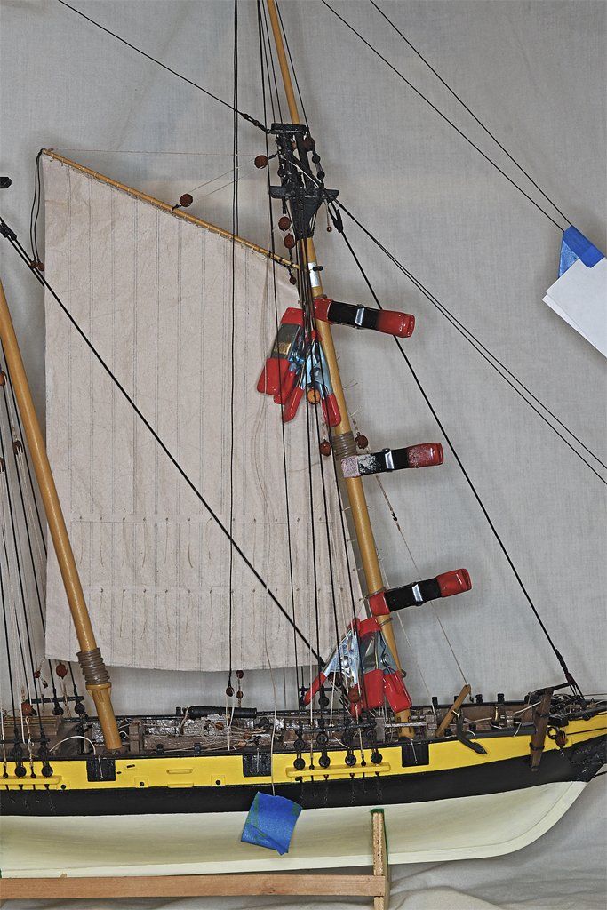
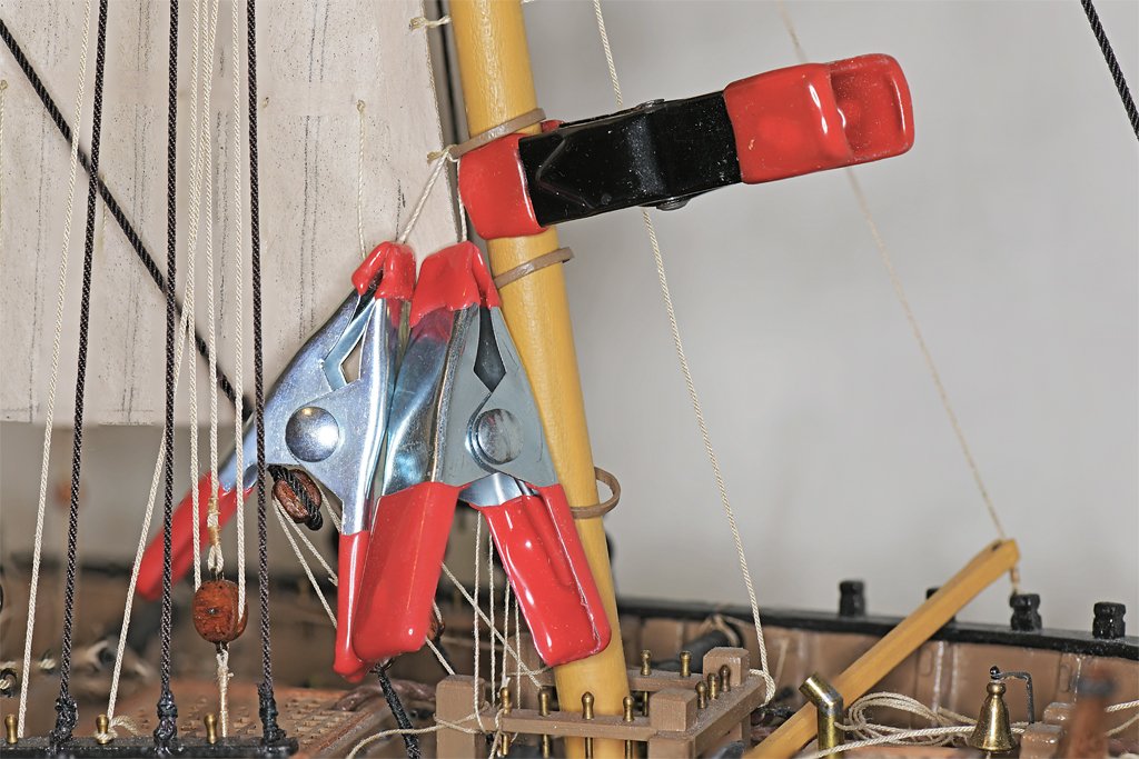
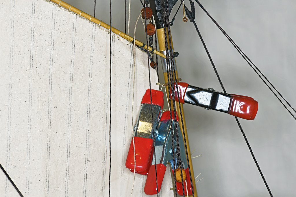
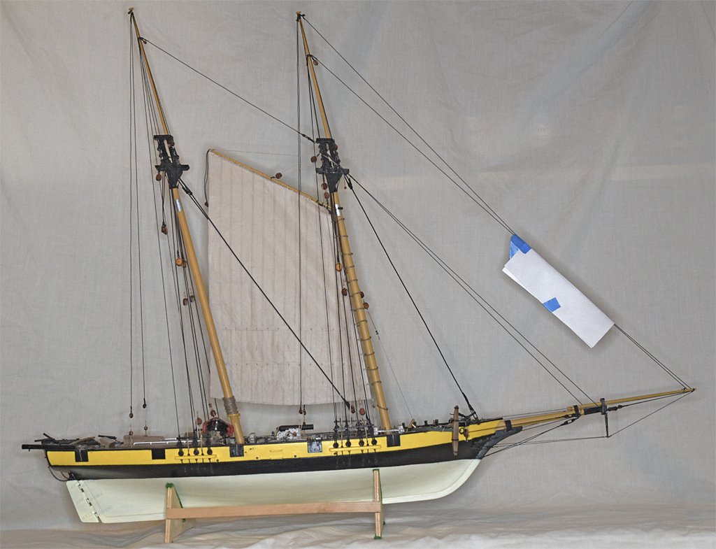
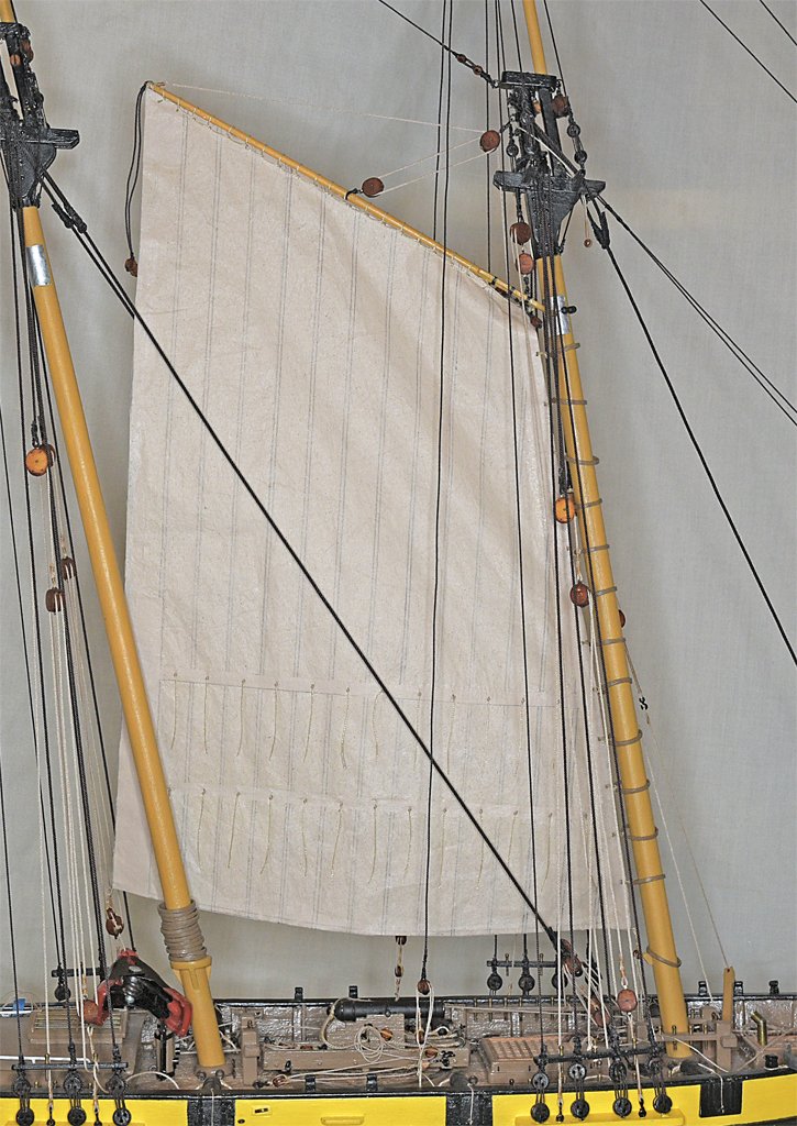
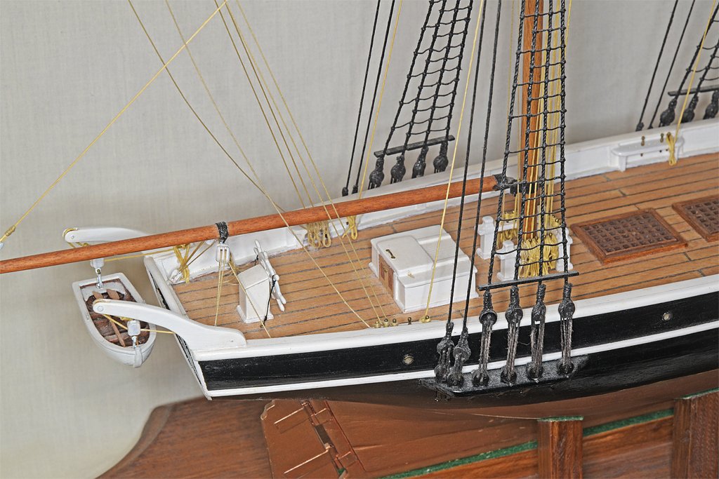
The foresail is rigged (mostly) on the mast! I chose to start with this sail because it is low on the mast, and the hoops will be inside a cluster of rigging when the other sails on the mast have been rigged. There were quite a few "obstacles" in the standing rigging as it is. I lifted the group of hoops to about the middle of the mast and used a clamp to hold them there. One by one they were raised or lowered to the position of the lines tied to the sail and held there with additional clamps until they were tied to the sail. Near the mast top the standing rigging lines crowded the work a bit. Lower on the mast I had a bit more room to work. The two lines from the sail were wrapped around the mast hoop, one over the top and the other under the hoop. They were brought back aft and held with clamps. I put a small drop of fast-drying Duco Cement on the ropes inside the hoop to hold them in place. This cement dries shiny, but it won't be visible inside the hoop. On the outside the lines were soaked with while glue diluted 1:1 with water. After the glue dried the loose ends of the lines were trimmed close to the hoops. The lines are not knotted around the hoops, but are held in place only by the glue. The hoops will be under no strain on the model so I hope the glue will be all that is needed! Here is a picture of the sail fastened to the mast hoops. It hangs pretty good from the gaff and along the mast. However, there is a bit of crowding under the gaff jaws and a noticeable wrinkle in the sail. I can live with that. The gaff peak halliard and throat halliard are rigged and tied to pins on the port and starboard bulwark pin rails respectively. The sail's tack is rigged to a luff tackle attached to a ring bolt in the deck just aft of the mast. The running end is belayed to a pin on the starboard side of the fife rail around the base of the mast. I have not rigged the sail's sheet yet. The line and tackle are attached to the sail but are just held down with a clamp in the photo. I want to be able to pull the sail aside while I am rigging the lines for the sails on the main mast. The sail's brail has not been rigged to the sheet cringle yet - I forgot it in the rush to get this sail hung! I may regret that when I get around to rigging it. The vangs are still to be rigged after the main mast rigging is finished. Here is a photo of the vessel as it is now. One sail down, eight more to go! Note: The white paper "flag" on the lines from the jib boom is to warn me to not get tangled up in them. The dark brown lines are hard to see against a cluttered background. Immediately after rigging the jib boom a button on my shirt sleeve caught one of the lines and jerked the boom pretty hard. One of the jib boom stays broke and I had to rig it all over again! Just another one of those lessons learned the hard way!
-
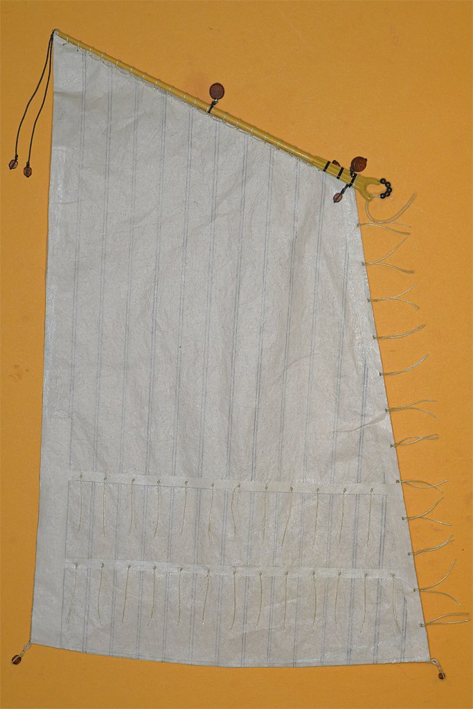
I have a bit of progress to report. Work on the sails was tedious and the rigging promised to be even worse, so I decided to take a break from the schooner build for a while. However, I have been doing some small fiddly bits ever now and then so it hasn't come to a complete halt. In the mean time I have started my model of the USS Cape MSI-2. While I am waiting for a wood delivery to continue the Cape I have started work again on the schooner sails. This reminds me of the tedium of the earlier build. Again, I am spending too much time on the floor searching for little pieces that suddenly disappeared! This is the fore (gaff) sail with all the trimmings. I have decided it will be the first sail to be rigged on the model. It is laced to the fore gaff along the top. I have added lines on the forward (luff) side to attach to the mast hoops. These are looped around the sail and bolt rope and glued in place. The two ends will be wrapped around the wooden hoops and glued together on the inside of the hoop. There are 12 ties for hoops, and there will be a 13th spare hoop at the bottom. Blocks for the sheet and tack tackles are attached to the cringles at the lower sail corners. The tack luff tackle attaches to a ring bolt at the base of the mast and the fall belays to a pin on the fife rail at the base of the mast. The sheet gun tackle attaches to a ring bolt on deck near the base of the main mast and the fall belays to a nearby cleat. Blocks for the peak halliard and throat halliard are attached to the gaff. These halliards belay on the pin rails outboard of the masts on the bulwarks. Pendants for the gaff vangs are hanging from the end of the gaff. The vangs attach to ring bolts just forward of the after pin rails on the bulwarks, run through the blocks on the vang pendants, and the falls belay to a pin on the after pin rails. Under the jaws are blocks for the brail. The brail attaches to the sheet cringle, runs through the block under the jaws, and then belays at the fife rail at the base of the mast. The next step will be to rig the sail on the mast.
-
Bit of a problem! HMS Speedy, Vanguard Models
Dr PR replied to JohnEvans's topic in Masting, rigging and sails
John, Replacing the broken piece won't be much of a problem. You don't have rigging in place yet. However, the suggestions to splice the break are not too far fetched. All of the rigging exerts a downward force, and that will hold the pieces together. And the different stays and lines balance each other if you get them rigged right, so the mast shouldn't try to bend. When installing the rigging do not pull the lines tighter than the minimum force necessary to get them to stand straight without sagging. You really shouldn't be putting much strain on the masts and spars. -
Brig Freya 1840 - FINISHED - 1:100
Dr PR replied to Dr PR's topic in - Kit build logs for subjects built from 1801 - 1850
They are current photos. If you look closely you can see dust that has accumulated with time - it doesn't have a case. I occasionally clean it, but it has been several months since the last cleaning. -
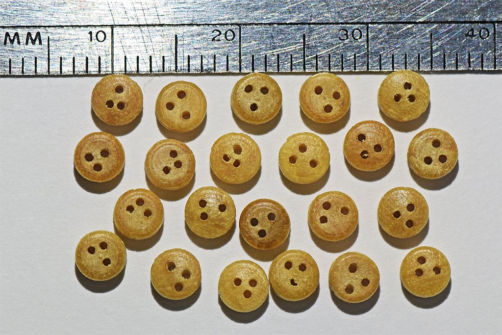
bcd, Welcome to the real world! I bought a bunch of deadeyes from a well known model company and they were mostly crap! Do these guys have trained monkeys making parts for them? Look at the photo - the holes are almost randomly spaced! Only about half of the parts were useable - the rest were junk! I won't be buying anything from A**** again!!!!!!!!!
-
Gregory, Thanks for the obvious question! I don't know about the forward or backwards spin, but I always went up the (inclined) ladders facing them, and down with my back to the steps. External (outside, weather deck) ladders usually had hand rails that continued up to the tops of life rails or life lines around the decks. Internal ladders had nothing like this. At the top there were no handholds. When you climbed them you just stepped out onto the deck, just like climbing stairs in a building. However, in heavy seas when the ship was pitching heavily over large swells, navigating internal ladders could be challenging. I can remember more than once when I was climbing a ladder in typhoons when the ship dropped out from under me, leaving me floating weightless in the air. But not for long before the deck came up to slam me! With experience you lose your lubber's legs and learn to get along no matter how the ship is pitching and rolling.
-
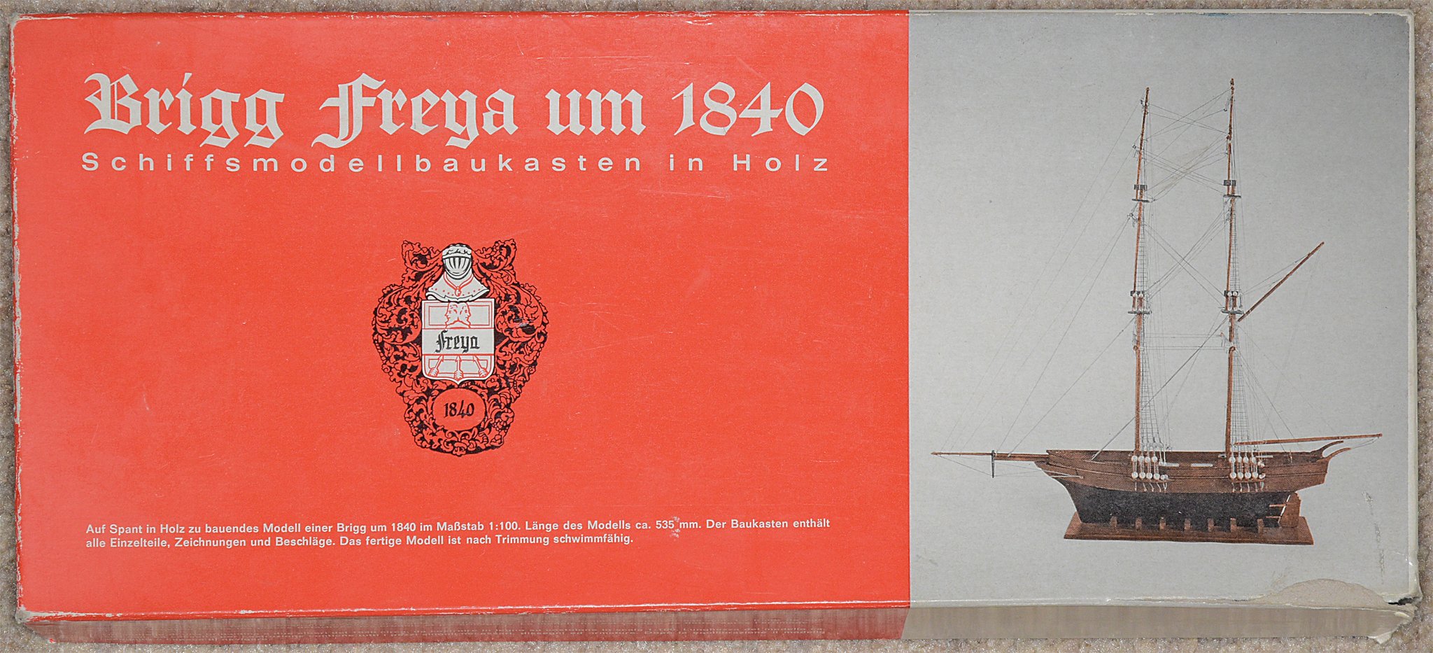
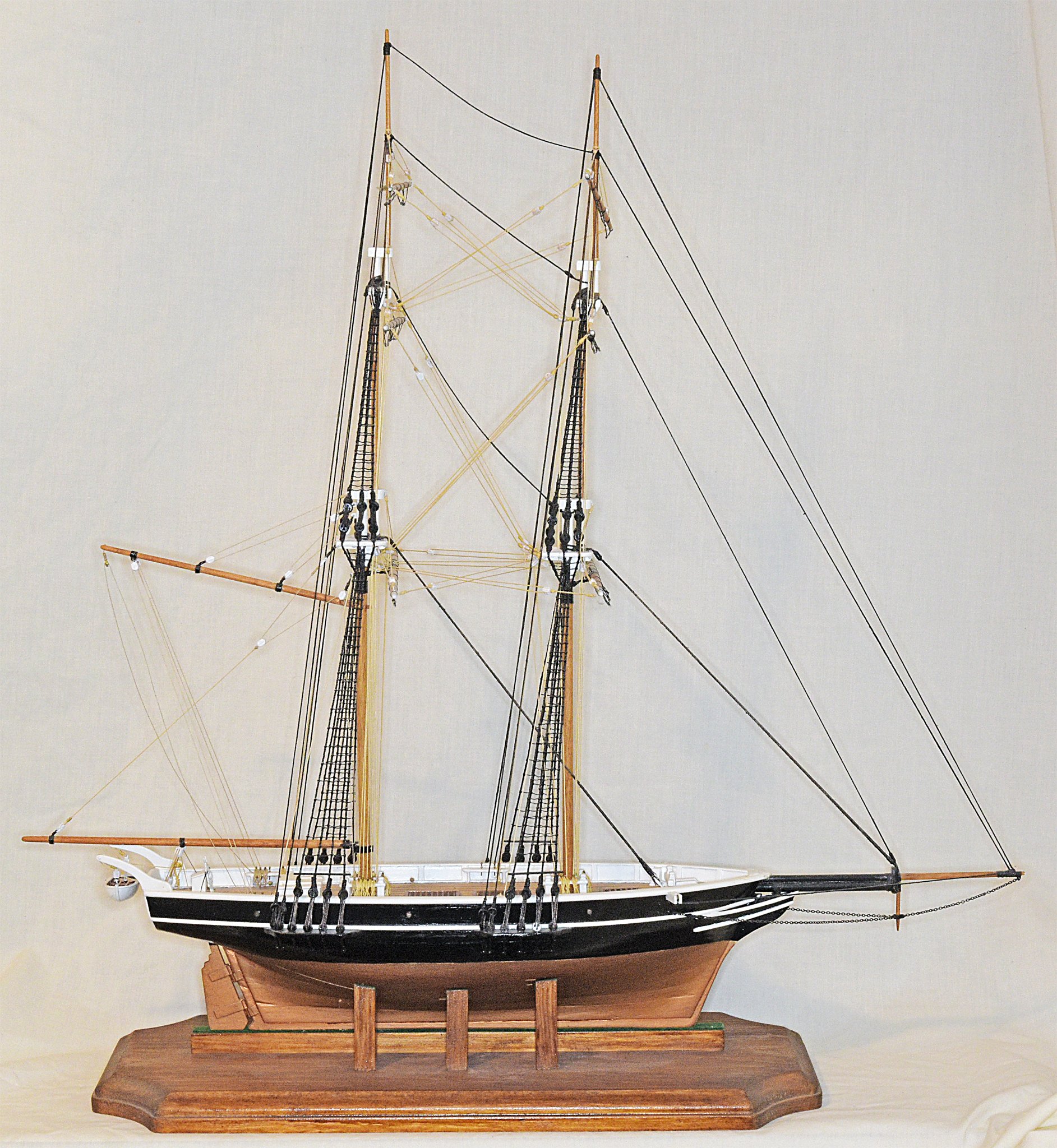
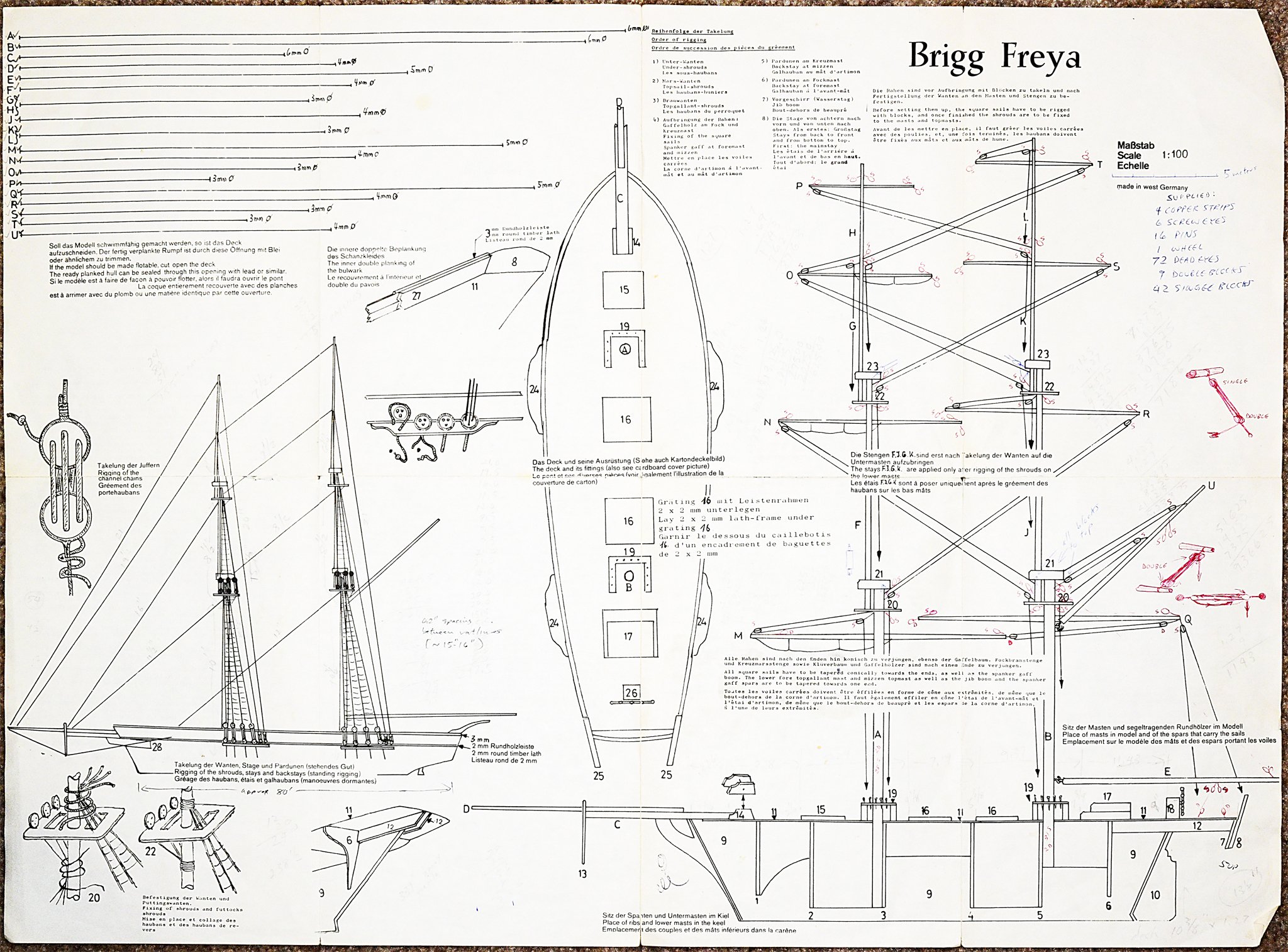
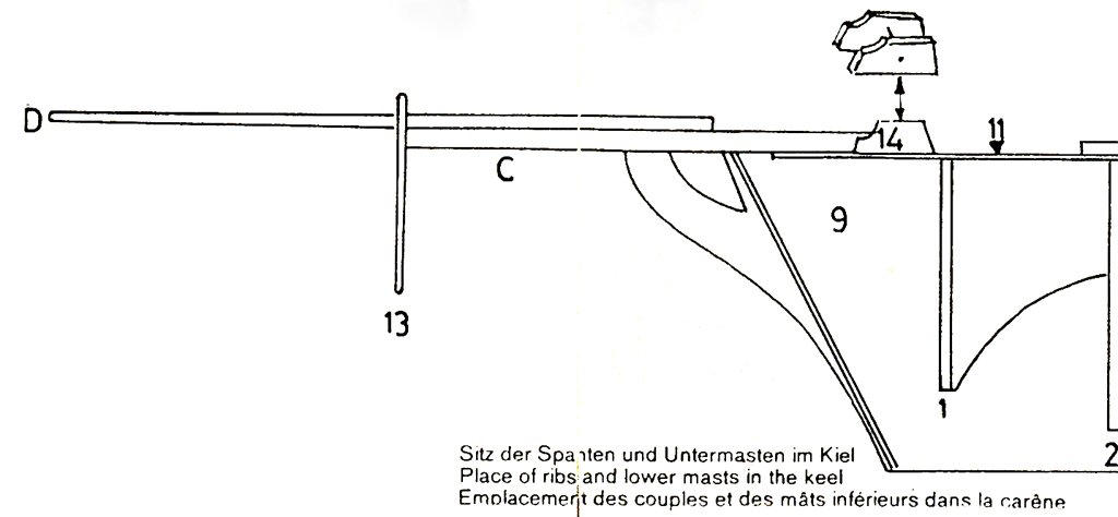
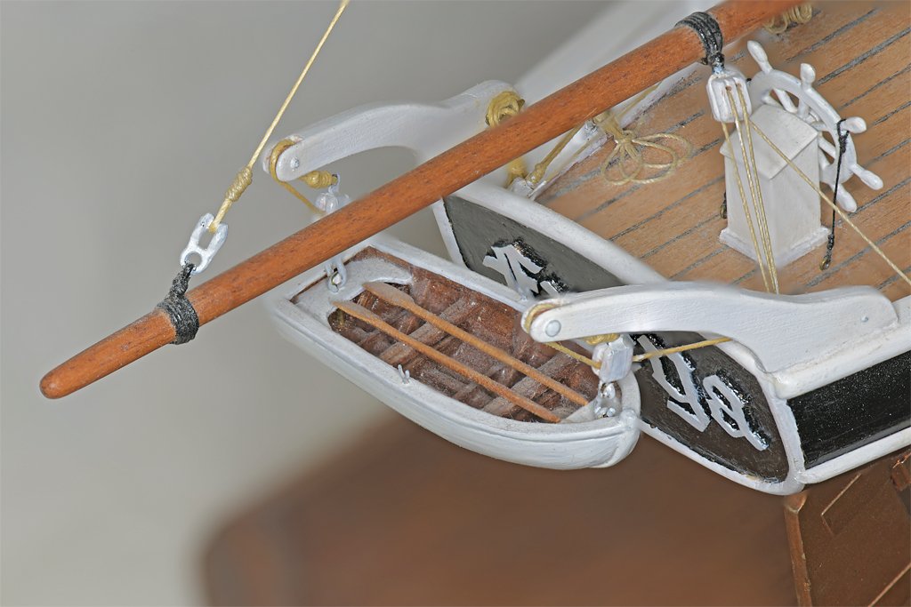
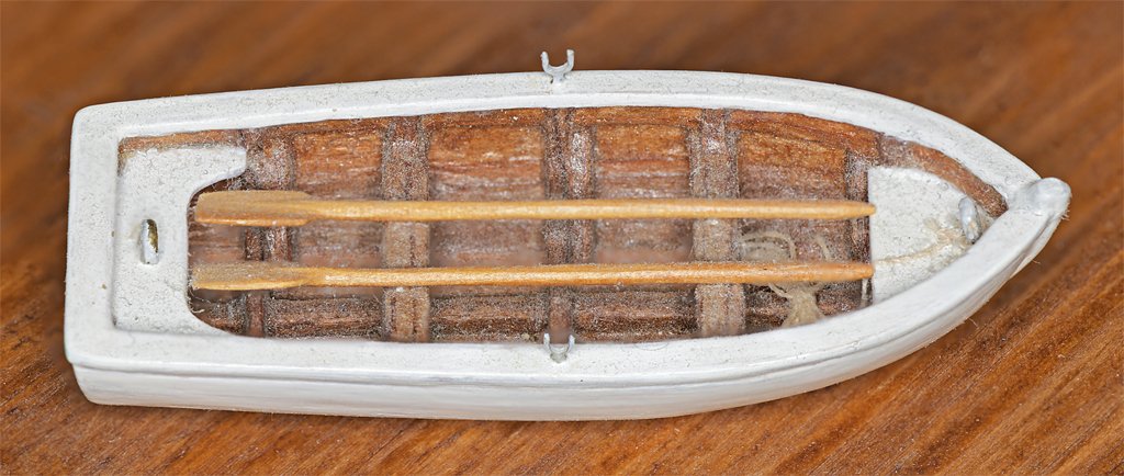
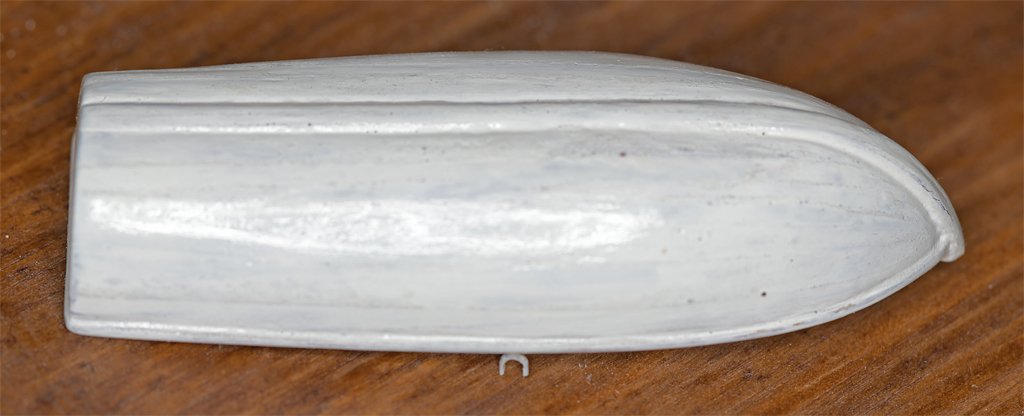
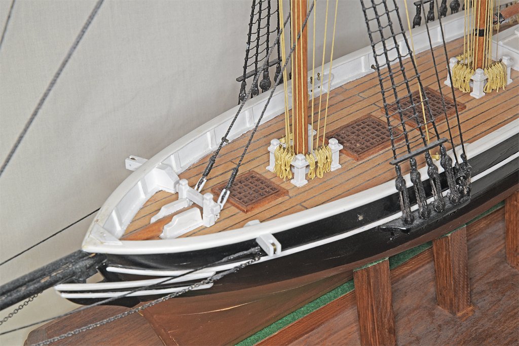
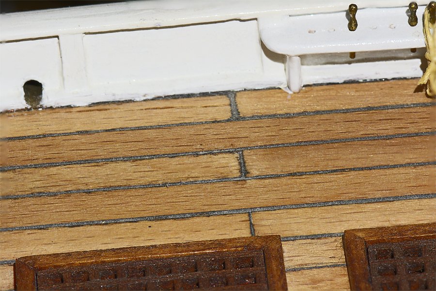
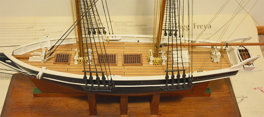
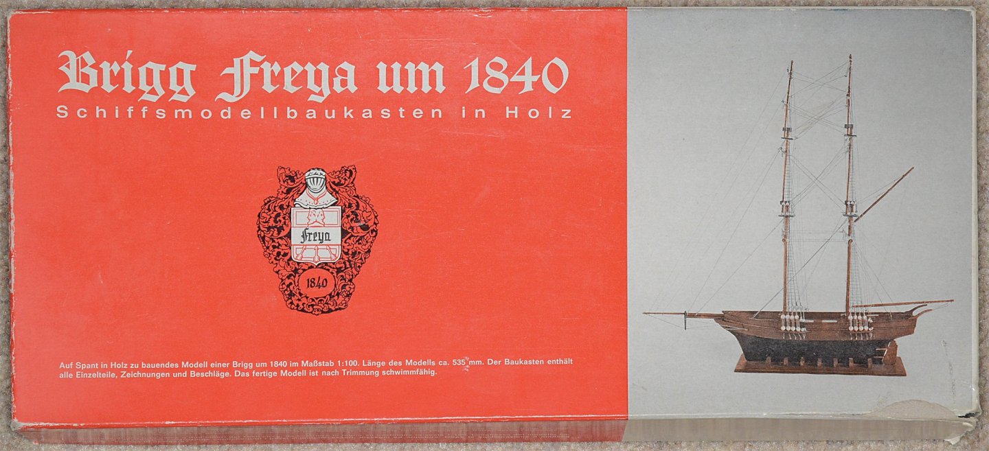
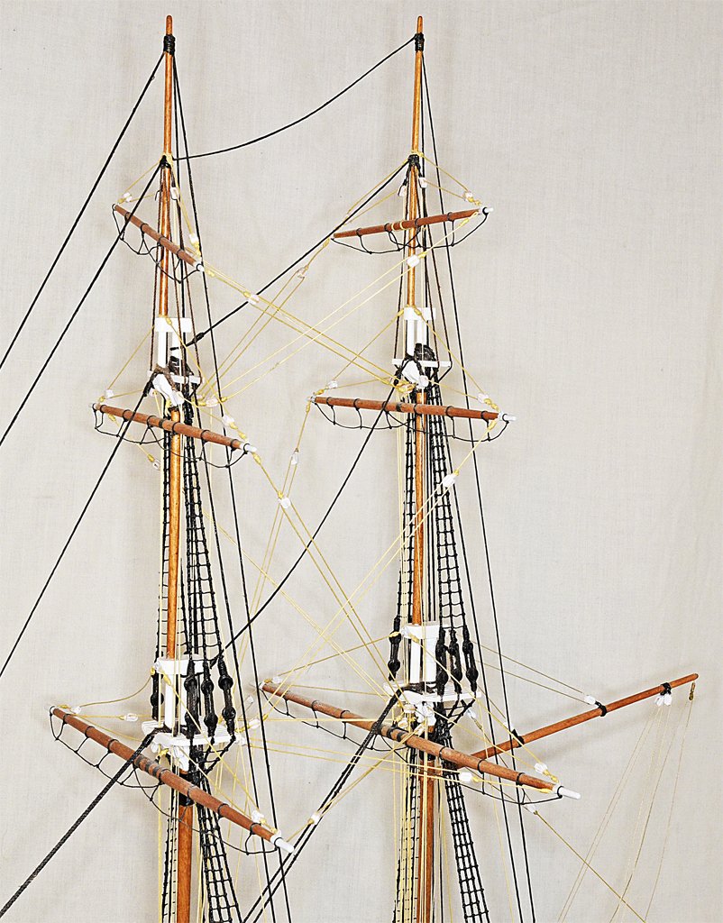
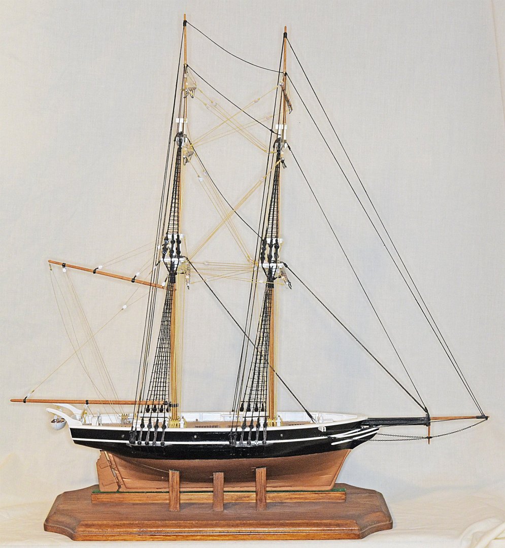
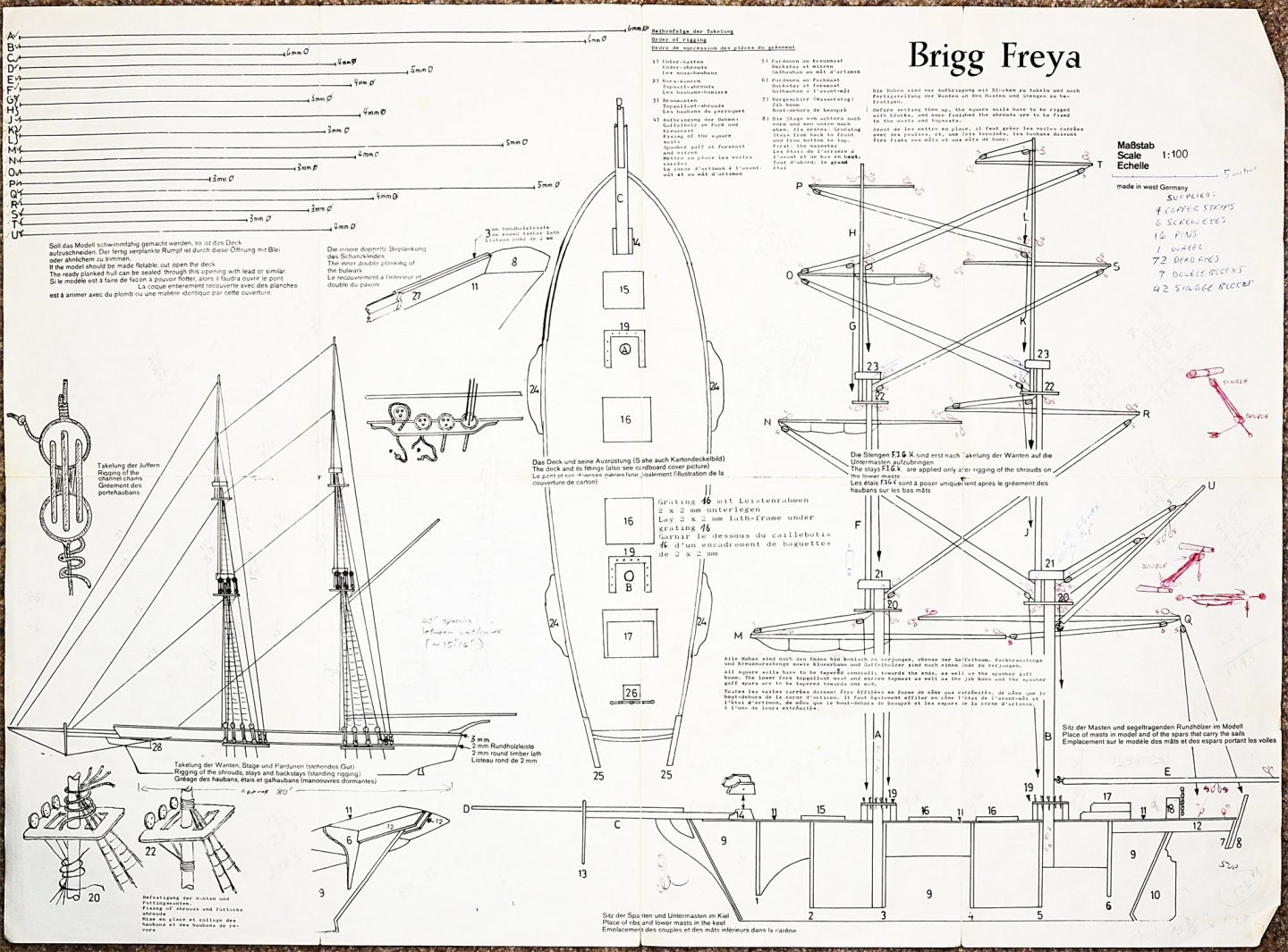
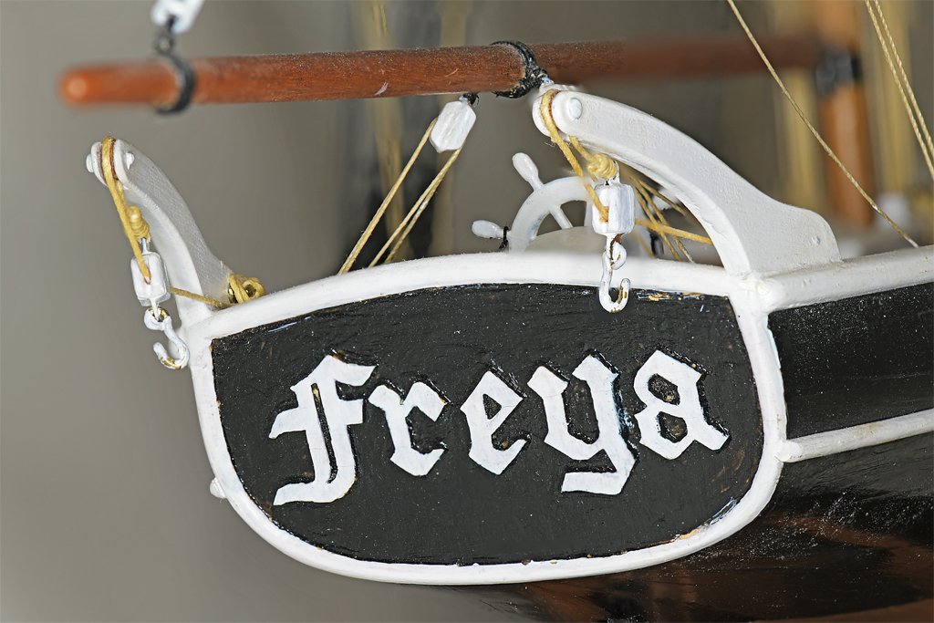
This Freya build probably should be considered ancient history because I built the kit in the mid 1970s. But I recently saw a kit on eBay for $70.00, so it might be of interest to someone. Also, I think the kit has been released again as the Agilis "clipper:" https://modelshipworld.com/topic/23067-agilis-by-jct-finished-steingraeber-160-scale-slave-ship/#elControls_682192_menu I am also posting it because there are some peculiar features to this model and I am hoping some of our members who are familiar with German and Danish ship construction might comment on it. Here is a photo of the kit box. "Brigg Freya um 1840. Schiffsmodellbaukasten in Holtz." A ship model kit in wood, and instructions mostly in German. Well, I majored in chemistry as a freshman and I was required to take two years of German because a lot of the chemical literature was in German. So a few (and I do mean a few) instructions in German weren't too daunting - at least in the 1970s. There is no kit manufacturer's name on the box or the instructions, but it does say "made in west Germany" on the plans. Newer modelers might compare the sparse instructions and lack of pre-cut parts to more modern kits. The other side of the plans sheet has instructions in four languages (German, English, French and Italian). There is a list of parts and 22 building steps. For example, step 20 says "The yards must be rigged and attached to the mast, following the drawing." There are a few helpful hints in the drawing. The parts for the hull had to be cut from a sheet of plywood that had lines printed on it. All the dowels for the masts and spars had to tapered by hand. Here is the finished model. I do not know if it actually represents any real vessel, but I had fun building it. This was my second kit build, and I scratch built many of the pieces because I thought the kit parts were too crude. When I look at it I am reminded of zu Mondfeld's comment (Historic Ship Models, page 218) about top heavy models that have overly tall masts. I have noticed that on many ships the masts are about as tall as the hull is long, or less. But in this model the masts are nearly 1 1/2 times as tall as the length of the hull. Are the masts too tall? Perhaps our Forum members who are familiar with northern European ships of the 19th century can provide some information about this. Another peculiarity is the angle (steeve) of the bowsprit - there is none. It is horizontal. The plans show it this way and that is how I built it. Were any real ships built this way? The tall masts and horizontal bowsprit suggest to me that this vessel never went to sea where it would encounter high winds and large waves. Perhaps it worked on rivers and other inland waters? Here are some more photos of the decks and masts. In the upper right hand photo you can see a place where a gap opened in the hull planking. This was probably caused by the wood swelling and shrinking as moisture changed in the atmosphere. This also happened on my first plank-on-bulkhead kit model. For all subsequent builds I have coated the inside of the hull planking with thin clear epoxy paint or epoxy potting compound. The epoxy penetrates the cracks between planks and between planks and bulkheads and makes the hull rock hard. I have a plank-on-bulkhead hull over 40 years old that was covered with epoxy inside, and it still does not have cracks between the planks! This was the first time I had planked a deck with individual pieces, and not a pre-printed single sheet. I had recently served on three ships in the US Navy that had wooden decks. On one the decking was replaced while I was aboard, and on another (USS Cape MSI-2) the plank seams were recaulked. I had saved some of the caulking compound that was used on the Cape just for the purpose of caulking ship model decking, and I used it for this model. So this is the real stuff you see here! Kids, do not try this at home! It was really messy and the seams are probably too wide!! The kit did not come with a ship's boat, and I thought it should have one. It did have davits at the stern for a boat, and I used the spacing between them to make a boat about to scale. Remember, this is long before the Internet and the information available there, and there were no bookstores where I was living with books about ships and ship modelling. The local hobby shops were either pushing flying model airplanes or model railroading. So I was winging it here! This is a 2.1 inch (53 mm) plank on frame model boat. At 1:100 this is a scale 17 foot (5 meter) long boat. According to May's Boats of Men of War it should have more thwarts and oars, but I didn't have access to such publications back then. I cut pieces for crude frames and glued them together. These were glued to a carved keel piece. And then the hull was planked with HO scale model railroad ties (the things that support the rails). I didn't know if this method would work, but I gave it a try anyway and the results were adequate for this model. Nothing ventured, nothing gained! I replaced a few of the parts in the model with scratch built pieces that were more detailed. I did have Chapelle's American Sailing Ships (my entire nautical library at that time) and used the illustrations in it as guides. The last major modification to the kit was the transom. The kit plans showed nothing there but the plywood piece. I thought the ship should have a name, and Freya seemed appropriate. Freya was the old Norse word for noble lady, and was the goddess of love and beauty. I learned a trick here that I have used several times since. I drew the letters on the plywood piece just like the printing on the kit box. Then I carved around them deep enough to cut through the outer layer of the plywood. Then I cut/peeled away the parts of the outer layer I didn't need. The rim around the transom was made in this way too. This left the letters in bas-relief. Of course, they are way too large! This method is useful for creating recessed panels in doors and wainscoting. So that is the story of my brig Freya um 1840 schiffsmodelbaukasten in holtz.

-
Tom, Yes and no. It has been a while (2018?) since I last did any 3D CAD modeling. I think that was the gun carriages for the schooner build. So at first when I started working on the venturi drawings I had to think a bit to get going. But then I realized that I didn't have to think about how to use the CAD program. I have been using the same program since 1988, and my hands are programmed - like a professional typist or a violinist. I just had to think about what I wanted to do and it happened! Of course, sometimes what I wanted to do wasn't right and I had to start over. But at least the mistakes came naturally!
- 464 replies
-
- 5
-

-
- minesweeper
- Cape
- (and 1 more)
-
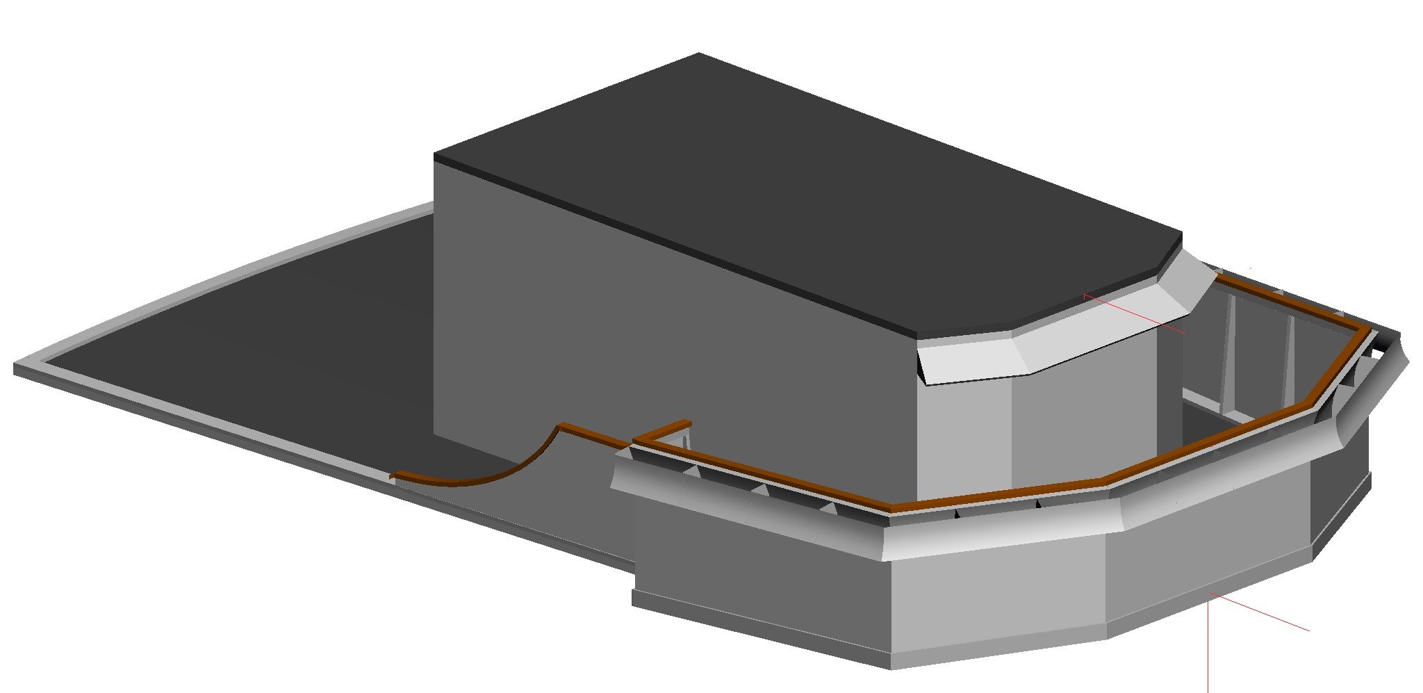
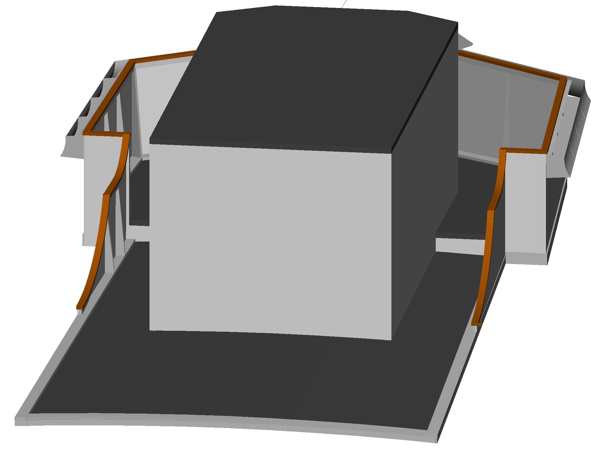
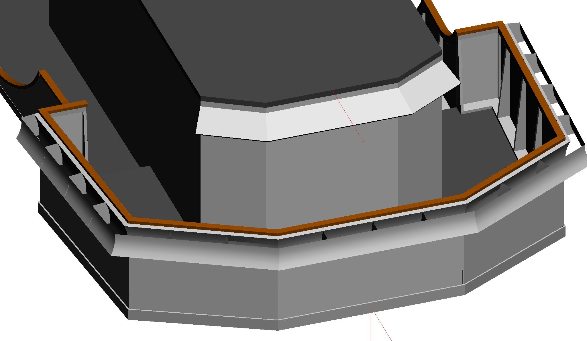
I realized that there were a few tweaks I needed to make to the visor and venturi to account for some odd angles in the superstructure. I started modelling the superstructure in 3D CAD so I could adjust the venturi. The visor fit without modification, but I had to angle the side pieces of the venturi to match the tops of the bulwark. The angles are non-intuitive. The blueprint doesn't give any dimensions for the heights of the side bulwarks, but just says the angle of the tops matches the sheer of the main deck. The bulwark section between the front and sides is angled at 30 degrees, and the outboard end determines the height of the bulwark side piece. The top of the bulwark side is parallel to the sheer of the main deck at the centerline. Try figuring that out on paper! After taking all of this into account the height and shape of the after side bulwarks, with the circular and elliptical curved top edges, came out just as the blueprints show them. I must have done something right! Another reason for the CAD model is determining the sizes of the wooden pieces I will use to build the model. I don't have a thickness sander or milling machine, so I must use parts that are available commercially. When I scale the dimensions shown on the blueprints to 1:48 the dimensions do not match anything I can buy. What you see in the CAD model is made up of pieces sized to commercially available parts that are the closest I can get to the scale pieces. Generally the differences between the scale dimensions and what I can buy are in the range of 0.010 to 0.015 inch (0.25 to 0.38 mm). That won't be noticeable on a 28 inch (711.2 mm) long model. By the time I get all of the minesweeping gear and other deck fittings figured out I will just about have a complete CAD model of the ship.


- 464 replies
-
- 9
-
-

-
- minesweeper
- Cape
- (and 1 more)
-
Actually, it looks to me he is thinking "Why is he wasting time on all this stuff when he could be petting me?"
-
Gap on flat bottom
Dr PR replied to WGibson's topic in Building, Framing, Planking and plating a ships hull and deck
You might not want to fill the gaps between the planks if you want the individual wooden planks to be visible on the model - they would be on the full sized vessel. However, Mark's suggestion is a very useful way to fill gaps that you don't want to see, especially where the parts will be painted. -
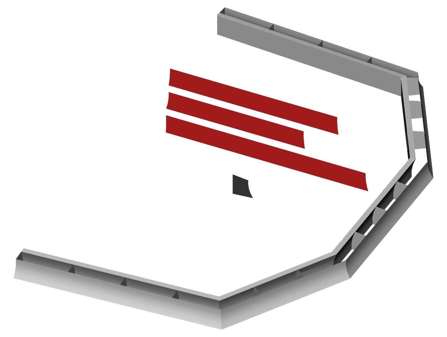
I want to make many of the parts for this build out of brass. I like working with brass and I have been soldering things since I was a kid. I plan to make many of the pieces with photo etching. Here are some of the parts that I needed to use 3D CAD to design. This is a "visor" or sun shade that fits above the front windows of the pilot house. Because of the multiple angles involved the three major surfaces are trapezoids. The two smaller pieces are the supports that fit under the upper surfaces. I wouldn't be too much trouble to make these by trial and error since I have the blueprints for the visor. But 3D CAD lets me determine the exact shapes, and photo etch will produce parts that will fit together precisely. This "venturi" is a much more complicated structure. It catches air blowing against the bulwark around the open bridge and literally funnels it up between the inner and outer surfaces. The openings at the bottom are larger than the openings at the top, so the air is compressed, and therefore accelerated. The resulting stream of air is forced upward over the bulwark. This rising column of air intersects the wind blowing from ahead and deflects it upward. I was amazed to see this really work! I have stood on the open bridge in a driving rain storm and for a few feet behind the bulwark no rain blew on me - it was all blown up and over by the blast of air from the venturi! The three different front surfaces are shown in red after they have been flattened. These are the pieces that will be photo etched. There also are 15 of the support pieces like the one shown in dark grey. All I will have to do is figure out how to solder all of these things together into a complete venturi! The most complex part so far is the funnel. The lower part is a truncated elliptical cone. The funnel cap is another truncated elliptical cone with skewed axes. The actual shapes of the funnel and cap are shown at left in grey. The unfolded flat surfaces are shown in red. There is no way I could ever have figured this out by trial and error! There are a few more flat pieces that are not shown, and I will modify the unfolded funnel piece to include some vent openings in the aft side. I love 3D geometry and figuring out all of these things is one of the reason I wanted to make this model. This isn't the first funnel that I have "flattened" in 3D to determine the surfaces. I did this many years ago for the funnels on my USS Oklahoma City CLG-5 model. That was the initial learning curve. I photo etched the 1:96 scale CLG parts at home - with mixed results that I am not satisfied with. I don't want to mess with it this time. Now I just need to find a photo etch supplier to make the parts.


- 464 replies
-
- 7
-
-
-
- minesweeper
- Cape
- (and 1 more)
-
The problem I had with the home etching kit offered by one supplier is that the photo resist did not develop uniformly. This left thin invisible film "blotches" on the metal that protected it from the etchant. Some parts came out OK, but most of the fine detail pieces were ruined. Eventually I gave up on it. I should say that I have been making printed circuit boards at home since the 1970s, so I am very familiar with metal etching. Of course those early PC boards had enormously wide traces and spaces (>0.05"/1.27 mm) compared to the last PC boards I designed before I retired (0.004"/0.1 mm traces and spaces). You can use Sharpie permanent markers to draw patterns on brass/copper and then etch with a water solution of cupric chloride. The pen ink serves as a resist, and if you don't try to have very fine traces or gaps you can make some pretty simple etched parts. This is how I made my first hobby PC boards. However, this method won't work to etch from both sides of the sheet because you can't align patterns on both sides accurately enough (at least for small parts). It will work only on very thin metal.
-
I need a variety of photo etch parts for a couple of models I am working on. I have made some photo etch parts at home, bit I haven't been too successful with the fine detail parts. I can produce the graphic images in many different formats. Can anyone recommend a photo etch supplier?
-
Many smaller vessels (100 foot or less) did not have a capstan or windlass. It all depended upon the weight of the anchor and cable. On smaller vessels the anchor could be weighed by just a few men hauling on the lines of a block and tackle. Here is a discussion of anchor handling on smaller vessels. https://modelshipworld.com/topic/27410-small-ship-anchor-handling/?do=findComment&comment=787942 Here is how I depicted this on my Albatros build: https://modelshipworld.com/topic/19611-albatros-by-dr-pr-mantua-scale-148-revenue-cutter-kitbash-about-1815/?do=findComment&comment=1015509
-
The quality of the wood in kits varies a lot. My experience with cheaper kits is that the planks can vary in thickness as much as 50%. If this is the case you have to grind down the thicker planks to match the thickness of the lower planks. You can mitigate the problem a bit by using the thicker planks near the centerline and the thinnest on the outboard sides of the deck. Johnny is right about coarser grits leaving deep scratches in the wood. t can be very difficult to remove these with finer grit sand paper! An alternative is to use a scraper to take off the high spots. A single edge razor blade (or just about any knife edge) will do. Just hold it perpendicular to the plank surface and drag it along, pressing gently, to scrape off the top surface. Use minimum force until you get the feel of it. Use 300-600 grit sand paper to finish it, and even #0000 steel wool. But be sure to remove all fragments from the steel wool before finishing the deck - they can rust with time and cause nasty discoloration of the wood!
-
Bob, I rigged the running stays on my Albatros build "loosely" before placing them and then tightened the lines as it would be done on the real thing. This did make it easier to rig them. But now I have the conundrum of whether to finish them tight and add the rope loops - or wait until I have installed the sails in case something needs to be loosened and re-rigged! Decisions, decisions ...!
- 207 replies
-
- 4
-
-
- vanguard models
- Duchess of Kingston
- (and 1 more)
-
For future reference. In my early college days (back in the Dark Ages) at a land grant university I had to take two years of Army ROTC. Part of our cannon fodder training was learning how to polish shoes and brass belt buckles. I guess it really impresses an enemy to find a corpse with polished brass! We used something called "Brasso" to polish the brass belt buckles, buttons and collar insignia. It apparently was composed of a solvent that dissolved oxides and a fine polishing compound. We rubbed it on with cotton and the brass shined up quickly.
-
Then why are we talking about hammocks and such? If bravado was so important why did ships have hammock cranes and nets? Why not just line the crew up topside as targets for the enemy to shoot at just to show who was bravest? I had my share of "spilling your guts for your country" lectures. And sailors were expendable, just like ammunition and toilet paper. But lives were not to be wasted foolishly. As Aubrey said in Master and Commander, "We must survive this day."
-
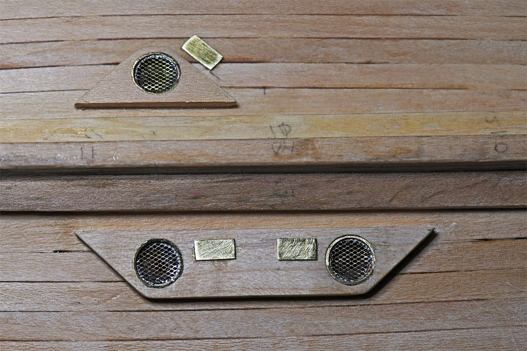
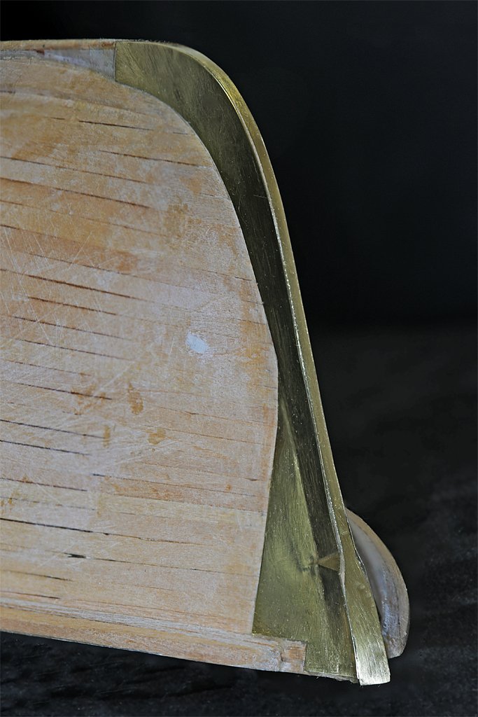
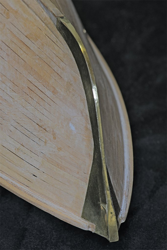
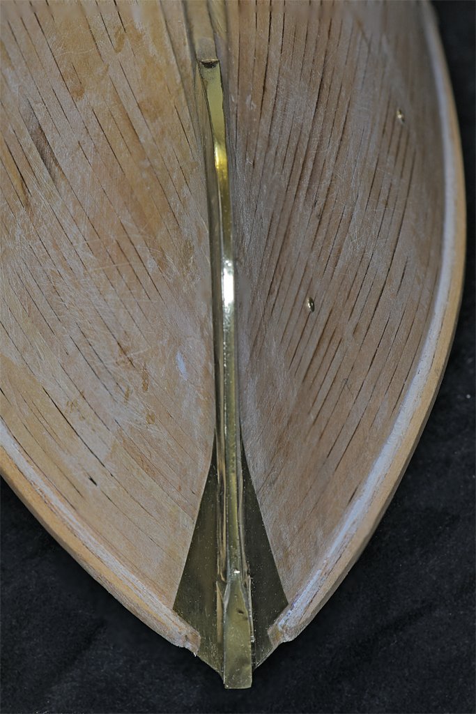
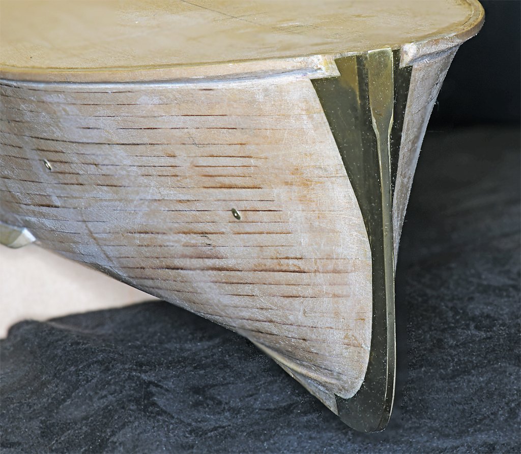
I think the stem bands are finally done! These things took a lot longer than I thought they would (primarily because I used the wrong glue)! I originally planned to install the strip that runs down the front of the stem as three pieces, as shown in the blueprints. But I decided to make it a single piece. I had already glued on the narrow strip between the top and bottom pieces. It served as a guide when I was removing wood to create the "V" shaped stem. I pulled it off and then shaped the stem a bit to accept a single piece. The new piece was wider at the bottom where the stem tapers from the wider keel to the narrow "V" shape at the bow. It is also wider at the top where the stem is rectangular in cross section. Between these sections it is a narrow strip of constant width. I don't know how many hours I fiddled with this piece! I had to file it down a bit, try to install it so see if it fit, file some more, etc. But it did come out quite nice. Not perfect, but nice. I didn't get it shaped perfectly where the top rectangular part tapers to the narrow strip. You can see the epoxy that fills the gaps here. But it will eventually be painted something like haze gray so it doesn't matter. While I was waiting for the epoxy to harden on the stem bands I installed the hull zincs at the engine cooling and fire system water intakes. After the hull is painted I will paint these something like a zinc color. Now I think the hull is pretty complete except for the stern frame and painting. I am waiting for the boxwood to arrive for the stern frame.
- 464 replies
-
- 15
-
-
-
- minesweeper
- Cape
- (and 1 more)
-
Using hammocks for "shielding" against bullets and shrapnel has been used for a long time, even up into the 20th century. Togo's flagship Mikasa at the battle of Tsushima in 1905 had bedding strapped to the railing around the bridge . And I have seen videos of Japanese aircraft carriers launching planes early in WWII, and they had bedding bundles lashed to the railings of the open bridge on the carriers. Now about using hammocks as shielding in the tops of sailing ships - if you were one of the fellows who would be in the tops to shoot at men on the other ship, and knew you were a easy target for anyone on the deck or in the tops of the other ship who were shooting back, what would you do? Since hammocks were recognized as useful for stopping small shot when placed on top of the railings, why would you limit their use to just this one place? If it was me and I was up in the tops, I would haul up anything I could get to hide behind!
-
USS Constitution by mtbediz - 1:76
Dr PR replied to mtbediz's topic in - Build logs for subjects built 1751 - 1800
Mustafa, I guess I agree with you that on your very nice pristine model a uniform finish would be more appropriate. But the finish you got on those carronades would be perfect on a model of a ship that had taken a beating in weather and combat! They actually look really nice! **** Note: I have had difficulties getting uniform blackening on brass parts. I always wash them first with liquid dish detergent and rinse with hot water to remove oils. Then I wash them in acetone to remove the soap and anything the soap missed. Sometimes I wash again with alcohol, but that is just to remove the acetone. Then I dry the pieces. Some people always etch the parts with Sparex No. 2 Granular Dry Acid Compound (sodium bisulfite) to "pickle" the surface. It needs to be heated and some users suggest getting a mini "crock pot" just for this purpose. I have tried using the blackening solution straight out of the bottle or by diluting it 1:1 with water. I have tried short (1 and 5 minute) blackening periods and longer (10 to 20 minutes). In every case I have gotten uneven coating. Longer blackening times seem to produce more surface coat that rubs off easily. -
The fingerprint is a type of corrosion caused by a chemical reaction on the surface of the brass/copper. These sort of stains can be hard to remove. A simple way to clean brass/copper coins that I used as a kid is to put on a drop of vinegar and then add baking soda. Use a tooth brush to scrub the metal. It fizzes and the baking soda acts like a polishing grit. If that doesn't work you can try using a polishing rouge. You can apply it by rubbing with a clean soft cotton cloth or by using a buffing/polishing wheel on a motor tool. The rouge will remove the fine scratches caused by the #0000 steel wool - just keep rubbing!