Dr PR
-
Posts
2,464 -
Joined
-
Last visited
Content Type
Profiles
Forums
Gallery
Events
Everything posted by Dr PR
-
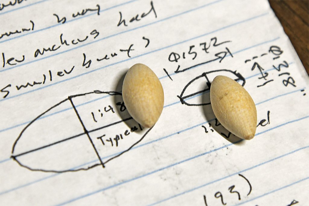
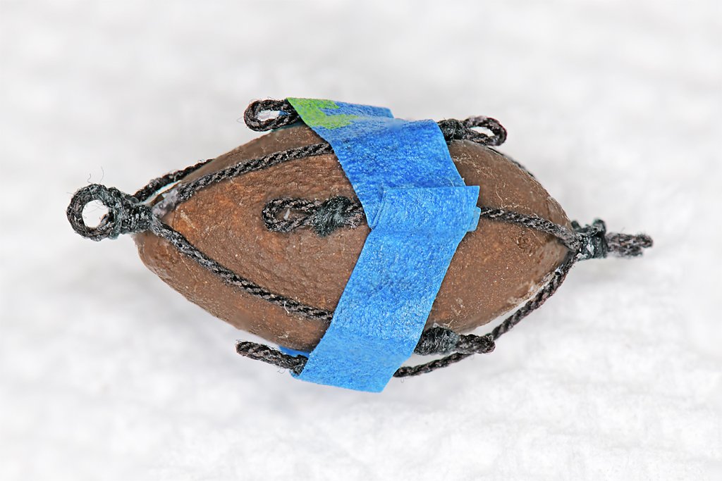
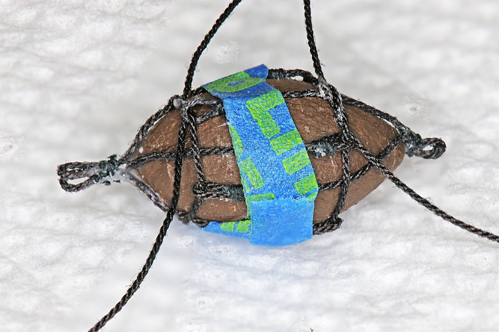
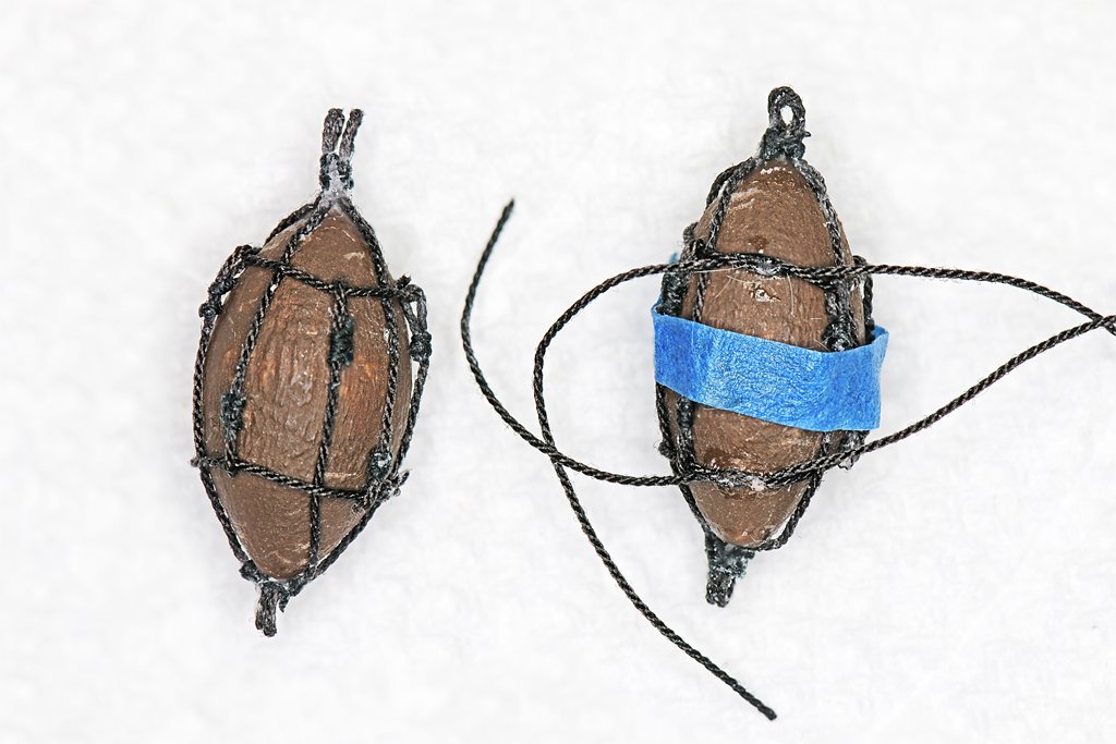
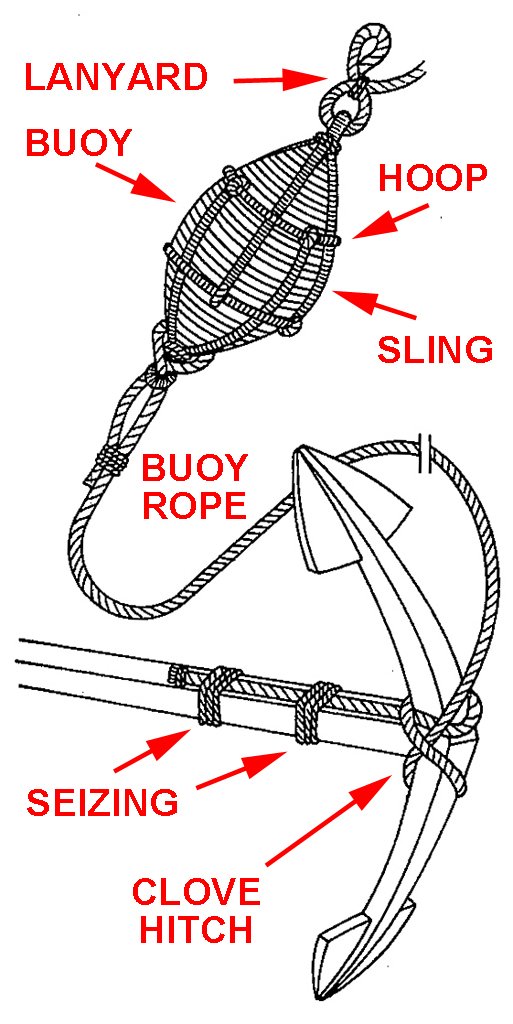
 ANCHOR BUOY Here is a drawing of an anchor buoy and anchor from zu Mondfeld's Historic Ship Models. The buoy could be anything that floats. Some were made of layers of cork, some layers of wood, and some were made with staves like barrels. One reference said they were covered with canvas and tarred to make them watertight and resist the effects of water exposure. The length of the buoy was 1/4 to 1/3 the length of the anchor shaft. The buoys were fastened into a rope "cage" made of slings and hoops. Every reference I found showed this same arrangement with four "arms" for each sling, all gathered into an eye. However, for small boat anchors there may be only two arms for each sling. Each arm of the sling had an eye. The rope hoops passed through the eyes and the ends of the hoop were spliced together to form a circle. When the hoops were pulled tight the slings were stretched and tightened to hold the buoy securely. The upper eye on the buoy was attached to a lanyard that aided in retrieving the buoy and fastening it to the foremost shroud. The lower buoy eye was attached to the buoy rope. Several references said the buoy rope was 1/3 the diameter of the anchor cable and a minimum length of about 18 fathoms (108 feet or 33 meters). The buoy rope was tied around the anchor crown with a clove hitch. The end of the rope was laid out along the anchor shaft and tied to it with seizing. There were usually two seizings near the end of the rope, with a buoy knot at the end of the rope. Most references show another seizing around the shaft and rope close to the crown and clove hitch. The buoy rope was coiled and lashed to the forward shroud at the deadeye. For modeling purposes the rope doesn't need to be a scale 18 fathoms. Several posts on the Forum tell of clever reuse of beads, toy footballs and other similar objects for the buoy. I just carved my buoys out of a round dowel using a hand drill and files as my "lathe.". One reference gave the dimensions of a "typical" buoy, but it must have been for a "typical" ship, whatever that is. It was much too large for my 1:48 scale schooner model! I used 1/3 the length of the anchor shaft for the long axis, and that came out to be 0.572 inches (14.5 mm). The diameter is 0.318 inches (8 mm). Of course these are approximations. What I ended up with is what came from carving the buoy from a 3/8 inch (9.5 mm) dowel. I coated the buoys with shellac to seal them. When the shellac dried I painted the buoys with burnt umber (dark brown) acrylic to simulate a tar coating. The next step was to make the slings from eight lengths of 0.025 inch (0.63 mm) rope with eyes at each end. I made a tool by driving two pins into a scrap piece of wood, then cutting off the heads of the pins. The spacing between the pins was a "guestimation" based on measurements around the buoy bodies with extra rope for the eyes at the ends and an eye in the middle where the slings will come together. The only way to know for sure if the length was correct was to make one of these things - if not I get the pleasure of making more slings. I tied off the end eyes with small black thread but you could just glue the two strands together. These things are pretty small and the seizing is not that noticeable. Two of these pieces were tied together in the middle, with an eye loop in both, to form George's "4 legged spiders" or what I called "quadropuses." The next problem was to figure out how to control the eight ends of the slings while trying to wrap them around the small buoys. This looked pretty tricky and I was prepared for "the slings and arrows of outrageous fortune" (pardon the pun, with apologies to Shakespeare) to befall me. Fortunately Murphy took the day off and what I had imagined to be a trying exercise turned out to be pretty simple. I placed a small drop of Loctite CA (cyanoacrylic) gel glue at the point of the buoy, and another on the sling below the central eye. I held the sling in place until the glue set. Then the buoy was inverted the the second sling was glued to the other end. I don't like CA, primarily because I have always had bad luck with it. Every tube I have used hardened almost immediately after I first opened it, so I usually got only one use from each tube. I prefer Duco Cement (nitrocellulose dissolved in acetone) because it sets pretty quickly (20 to 30 seconds) and I have had tubes last for decades. But for this job I wanted instant gratification when I placed the slings on the buoys. As my luck would have it, the cap of the CA bottle was glued permanently in place. But the entire top of the bottle screwed off so I got a few more drops from it. I didn't have any of George's small cocktail umbrella rubber bands - actually they reminded me of the little bands dentists place on kid's braces. Instead I cut thin strips of blue painter's tape and wrapped them around the slings and buoys. This actually worked pretty well. I could reposition the ends of the slings under the tape to get fairly even spacing around the buoy. Then the hoop ropes were threaded through the eyes on the sling arms and pulled tight. Looks like I guessed correctly for the length of the sling ropes! I only wrapped the ends of the hoop ropes around each other with one turn, and no knots. I put a drop of Duco Cement on the junction and worked it in with a needle point. There should be no strain on these ropes so the simple glue joint should be strong enough! Here are a finished buoy on the left and another in progress on the right. The CA cement left a white blob at the ends of the buoys and the Duco Cement leaves a shiny film. I will need to touch up these areas with burnt umber and flat black paint. After everything is dry I may coat the entire buoy with dilute white glue to hold the slings and hoops in position. I will have to wait until I have finished the ratlines before I can tie the buoys to the fore shrouds. My anchor cables are 0.065 inch (1.65 mm) diameter. The buoy ropes should be about 1/3 as large, so I will use 0.018 inch (0.45 mm) or 0.025 inch (0.63 mm) diameter tan rope.
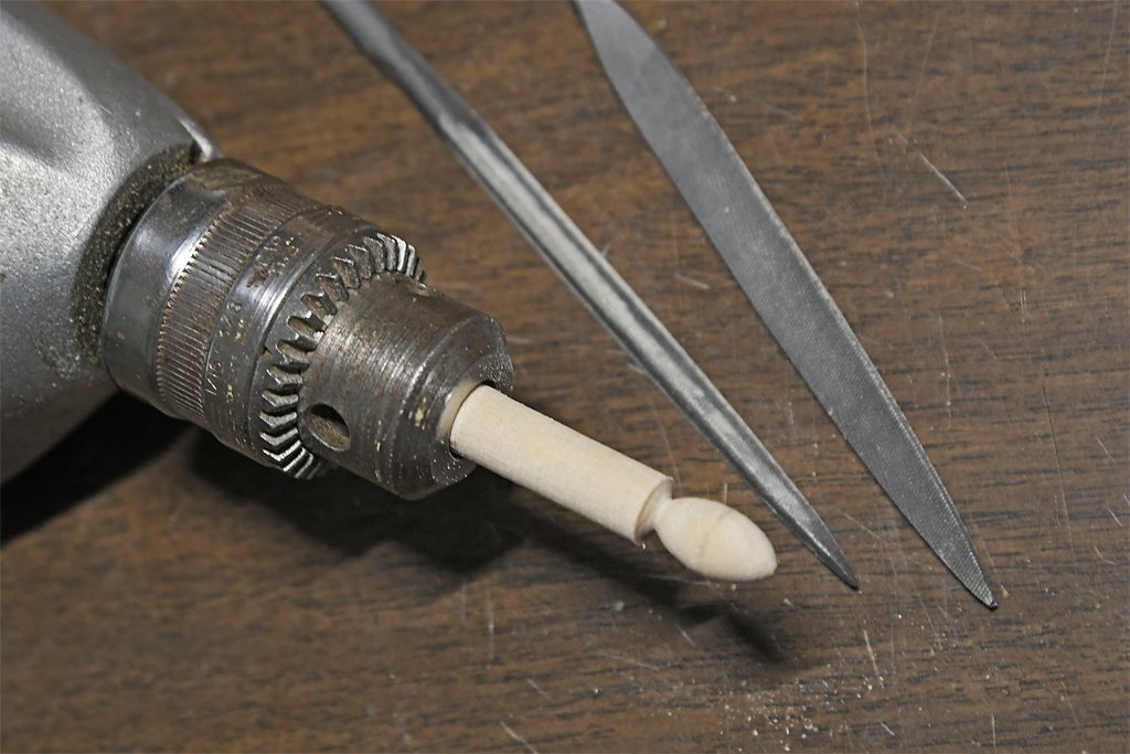
-
George, Thanks for the information. The file about anchors is well done. I have found most of the information, in bits and pieces, in several of the books I have. I was wondering how to tame all those loose ends and your idea of using a (very) small rubber band is good. I don't think I have any here, or if I do I don't know where to find them! I will try a thin strip of painter's tape. But I expect Murphy to be right there to "help" me!
-
Dowmer, Thanks for the link for the flag. I don't know if my printer (Brother LED printer) will print on paper that thin. It is a laser-like printer with a very hot fuser, and I can't run anything through it that might melt (would destroy the fuser). That rules out taping the tissue to a heavier sheet of paper. I'll try hand feeding the tissue paper - the worst that can happen is a paper jam. Farther down in Chuck's post he shows how he makes the anchor buoys. The longboat buoys are a bit simpler than what all the books show.
-
I have been doing a bit of calculations for the anchor buoy and ratlines. ANCHOR BUOY Marquardt (p 192) says a "normal" anchor buoy was 54 x 30 feet (1.37 x 0.67 meters). At 1:48 scale this is 1.125 x 0.625 inches (28.6 x 17 mm). This is almost as long as the shank of the anchor on my model! Marquardt does say smaller anchors had smaller buoys. I looked for photos of models showing the anchors and anchor buoys. I found four. A = length of anchor shaft (head to crown) B = length of anchor buoy Photo A B A:B 1 0.938 0.3215 3.00 2 0.319 0.109 2.93 3 2.78 0.922 3.02 4 0.328 0.147 2.23 So actual anchor buoy length is about 1/4 to 1/3 the anchor shaft length. Since my model's anchor is very close to actual scale for a schooner of the model's size, and the anchor shaft length is 1.716 inches (45.2 mm), the anchor buoy should be about 0.57 inches (14.5 mm) long, and (using Marquardt's proportions) about 0.318 inches (8.0 mm) wide. RAT LINES (Ratlings) Lever (p 25) says ratlines were spaced 12 inches (305 mm). Marquardt (p 172) says 12 to 16 inches (305 to 406 mm), with 13 inches (330 mm) most common. Lees (p 44) says 13 to 15 inches (330 to 381 mm). Mondfeld (p 288) says 15 to 16 inches (381 to 406 mm). Chapell (Fishing Schooners p 586) says 16 to 16.5 inches (406 to 419 mm). So there you have it. Ratlines were definitely spaced just about any distance you want! For my model, an American schooner, I will go with Lever, Marquardt and Lees 12-13 inches, or about 0.25 inches (6.4 mm) at 1:48 scale. I would rather use Chapelle's 16 inches because I would have to tie a lot fewer knots!
-
I have printed the flag, and the flag halliard is already in position. I am trying to figure out how to fold the flag so it hangs "naturally." I need to print it on lighter weight paper. I never visited the NROTC building at OSU. It used to be a Quonset hut down by the railroad tracks. I don't know where it is today.
-
I have had the same problem with some of my CAD designed parts when it came time to actually make them I'm afraid the computer design is more accurate than I am when I start cutting pieces. I always make parts a bit oversized. It is a lot easier to remove a bit than it is adding it back!
-
I just realized that I need to add the anchor buoys and rigging to the anchors. And I probably should put foot ropes (horses) on the bowsprit and jib boom. Wonder what else I will think of before this is done. Any suggestions?
-
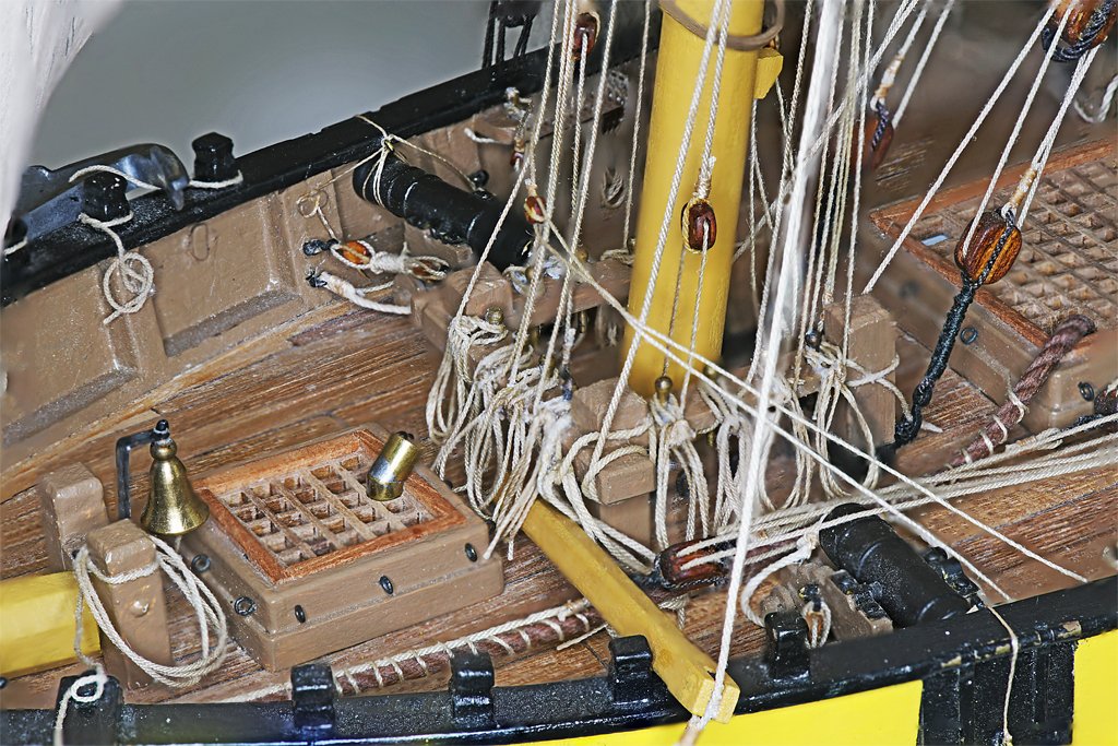
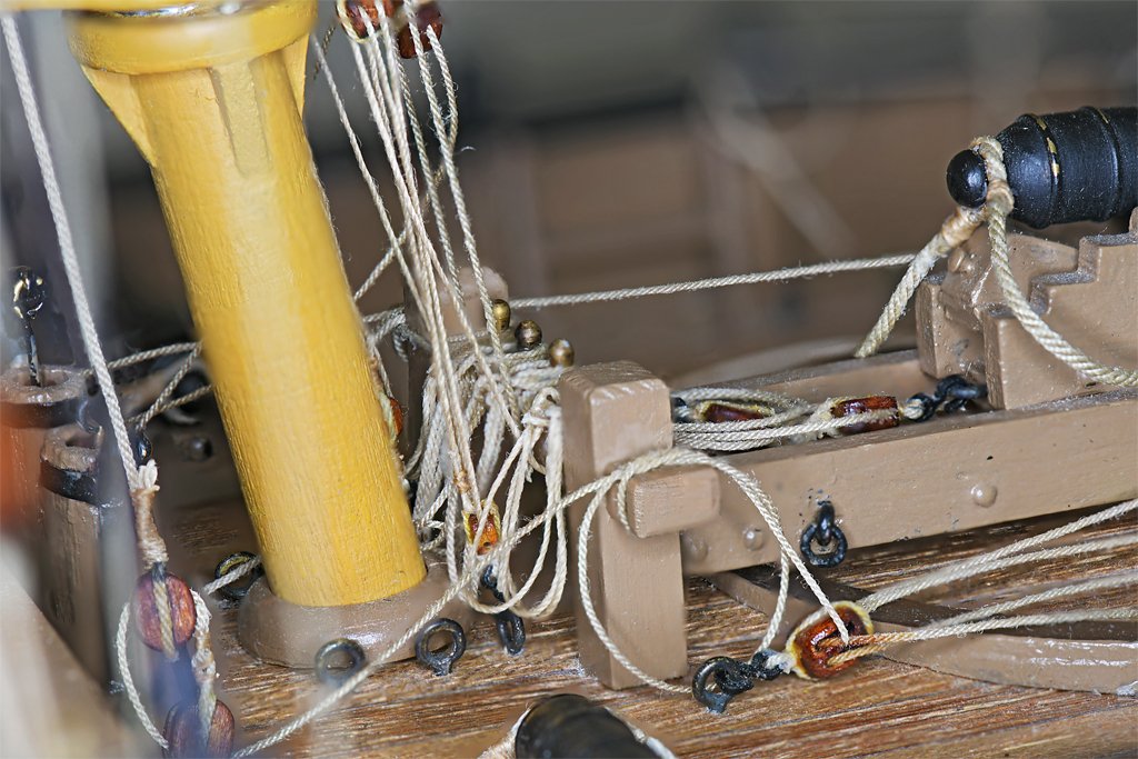
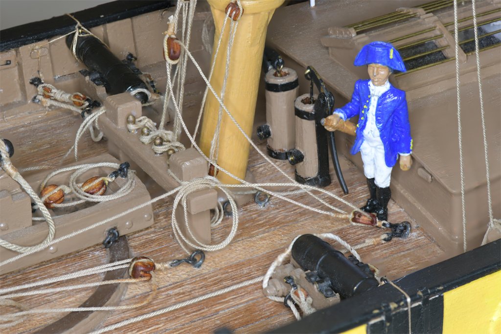
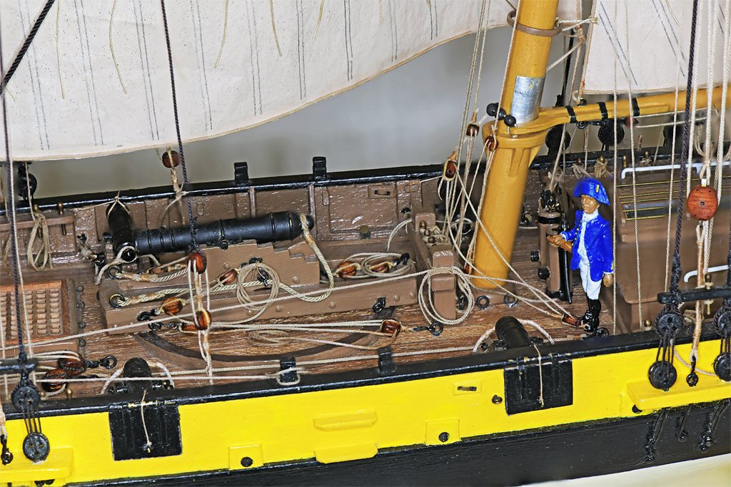
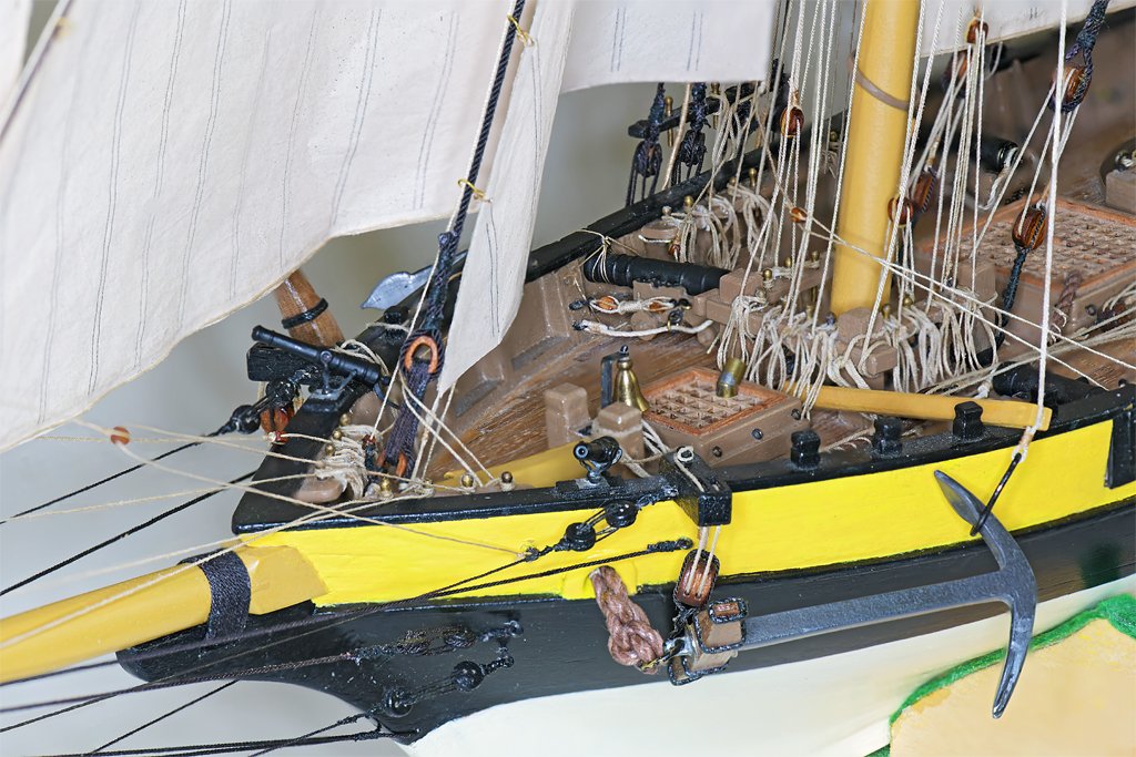
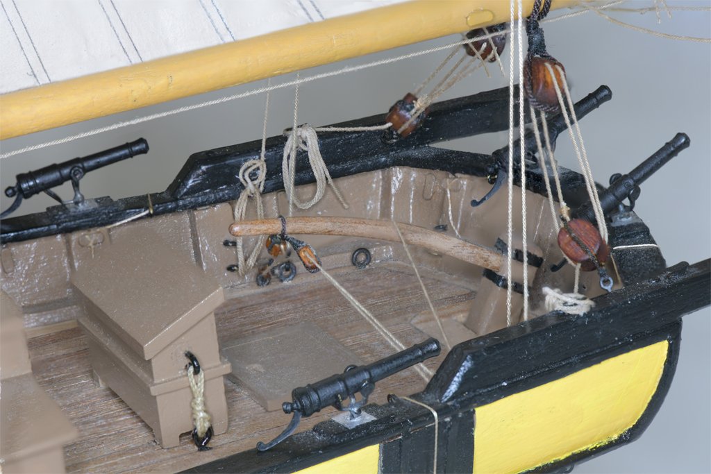
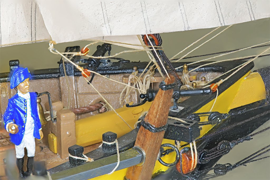
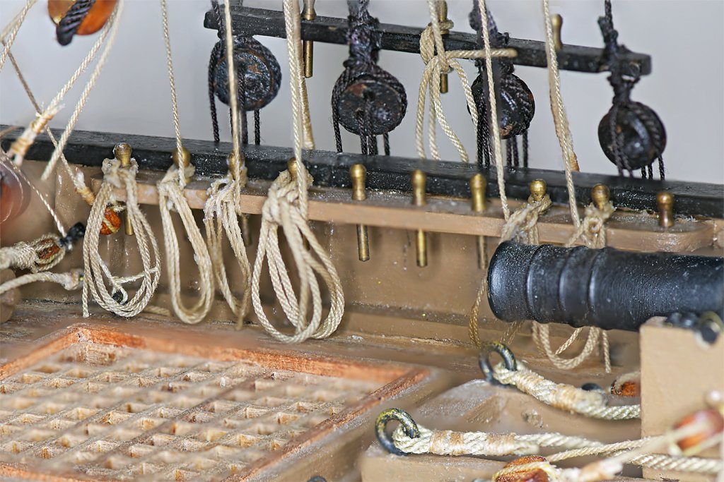
I worked for a couple of days to clean up the loose ends of the belayed lines and attach the rope loops. I left the lines longer than needed so they could be loosened and tightened as necessary to get them running right. The deck was a mess of loose ends looking more like a plate of spaghetti than a ship. After they were all glued in place I cut off the loose ends. Then I installed the rope loops I made in post #307. I did match the rope size in the loops with the size of the actual line, but I made no special attempt to make the rope coils any special length. In reality some would have more loops than others. Maybe on the next build! At the bow the lines from the fore sails belayed at pins on the port and starboard bow pin rails. Some of these lines are the sheets for the fore sails, and they must wrap around the stays of the sails farther aft. I haven't "tamed" them yet to hang in a realistic fashion. The sheets of the fore staysail pull the clew of the sail forward, causing it to fold back. I haven't figured out how I will fix this so the sail hangs more naturally. The fife rail at the base of the fore mast has many lines belayed to it. This was the most difficult part of the belaying plan - there were more lines than there were belaying pins. But by putting some of the tackle aloft - such as the yard lift gun tackles - the number of lines to be belayed and the crowding of tackles around the base of the mast was reduced. The area around the fore top is pretty crowded. The lines from high on the mast are routed through fairleads on the fore top crosstrees to eliminate tangles and chafing. Some of these lines had to be untied after belaying, pulled back, and rerouted several times to get all of the lines to hang without tangles and chafing! I was worried about getting the lines belayed and the rope loops hanging correctly on the bulwark pin rails because I had to work "blind" from outboard to get the lines hooked around the bottom of the belaying pins. The gaff sails hanging on the centerline prevented me from having unobstructed access from across the ship. It did take some patience and repeated attempts but I learned the routine and it wasn't as bad as I had imagined. The rope loops with two "eyes" to fit over the belaying pin worked nicely. I put a small drop of cyanoacrylate (CA) glue on the part of the loop that would rest against the pin rail. After the loop was in place I put diluted white glue on the top of the pin and the loops that fit over the pin. I think they worked out OK. I worried most about the four lines that belayed to the main mast fife rail. Access to these belaying points was the most restricted of all because of all the other rigging. The main problem can be seen in the picture left above. The pivot gun table is much too close to the fife rail to allow the rope loops to hang on the forward side. So the lines had to be belayed from the aft side of the rail. I made a wire hook to help pull the lines under the rail and loop them around the bottom of the belaying pins. The picture right above shows the rope loops hanging behind the rail. Fortunately there were only four lines to rig this way! There aren't many lines to belay at the stern. However, the lines there belay to cleats, and not belaying pins. This requires a different arrangement for the small loops that tie around the cleats. My pre-assembled rope loops weren't optimal for this belaying method. There are still a few more lines associated with the ship's boat to be belayed here. The ratlines and the boat are all that remain to be rigged on the model. I will be doing this bit by bit, while I resume my USS Cape build. I will also need to make a permanent base to display the ship. I did discover one more broken plastic hook - on the port cat block. Soon that will have a metal hook!

-
I use Squadron White Putty to fill small gaps that will be painted (it is white and stands out like a sore thumb if not painted). If you are filling larger gaps and cracks in hull planking there are better fillers. There was a lengthy discussion on the Forum a month or two ago about how to make wood fillers using sanding dust from the wood you are using and mixing it with something like white school glue (Elmer's Glue All or similar) that dries colorless. Smear the paste into the cracks and sand it after it dries. If the gaps are pretty wide (1 mm or 0.039 inch) I just shave off a thin strip of wood, taper the ends as necessary, and glue it into the crack. Use the same wood that you are planking the hull with and the filler will not be noticeable.
-
I agree with Trevor that you probably should have a bit more curvature in the planking at the bow. That would bring the point where they join a bit farther back. In your post #63 it looks like you didn't cut back the side pieces #21 at the bow far enough. Also, It looks like the hull sides are a bit too vertical at the top - in other words the planks should slope outwards more. This would cause the line of intersection of the planks (the stem) to angle back and intersect the gammoning knee a bit farther back. You could cut the planking back from the bow and reshape the filler to add some of curvature to the planking, and increase the outward "V" flare a bit. Or you can just live with it. No one else will notice on the finished model. The real problem will be finding a place for the gammoning ropes if the knee doesn't protrude far enough forward from the stem. I had that problem on my Albatross build. My solution was surgery on the bow to extend the gammoning knee. https://modelshipworld.com/topic/19611-albatros-by-dr-pr-mantua-scale-148-revenue-cutter-kitbash-about-1815/?do=findComment&comment=912575 One Lynx plan shows the gammoning ropes running under the knee and over the bowsprit, rather than the ropes running through an opening in the knee. However the Lynx model in the Smithsonian doesn't appear to have gammoning. Chapelle doesn't show gammoning in his drawings of Lynx or Musquidobit, although he does show this in drawings of other vessels. I have seen instances of where the gammoning was positioned inside the bulwarks at the bow. Unless you have drawings showing the the British added gammoning around the bowsprit and knee I think you can leave it off. And that means you don't need a long knee. In fact, some vessels had no knee at all, with the stem rising straight up to the bowsprit. The modern Lynx reproduction has a much larger decorated gammoning knee, but I can't see any gammoning in the photos I have. Murphy often gives us additional opportunities to practice our modelling skills.
-
There are days when nothing seems to go right. But it is amazing how a bit of sunshine can make things right again.
-
Nice planking job. Can't say as much for the Texas penguins! Kind of like the Wyoming jackalope. I am from Arkansas originally and we have learned to be leery of Texican exaggerations! But I do have relatives from Texas. My father's mother was an Austin, related to Stephen Austin, as in Austin, Texas. So I guess that gives me some immunity from exaggeration.
- 90 replies
-
- 3
-

-

-

-
- Friendship Sloop
- bluejacket shipcrafters
- (and 1 more)
-
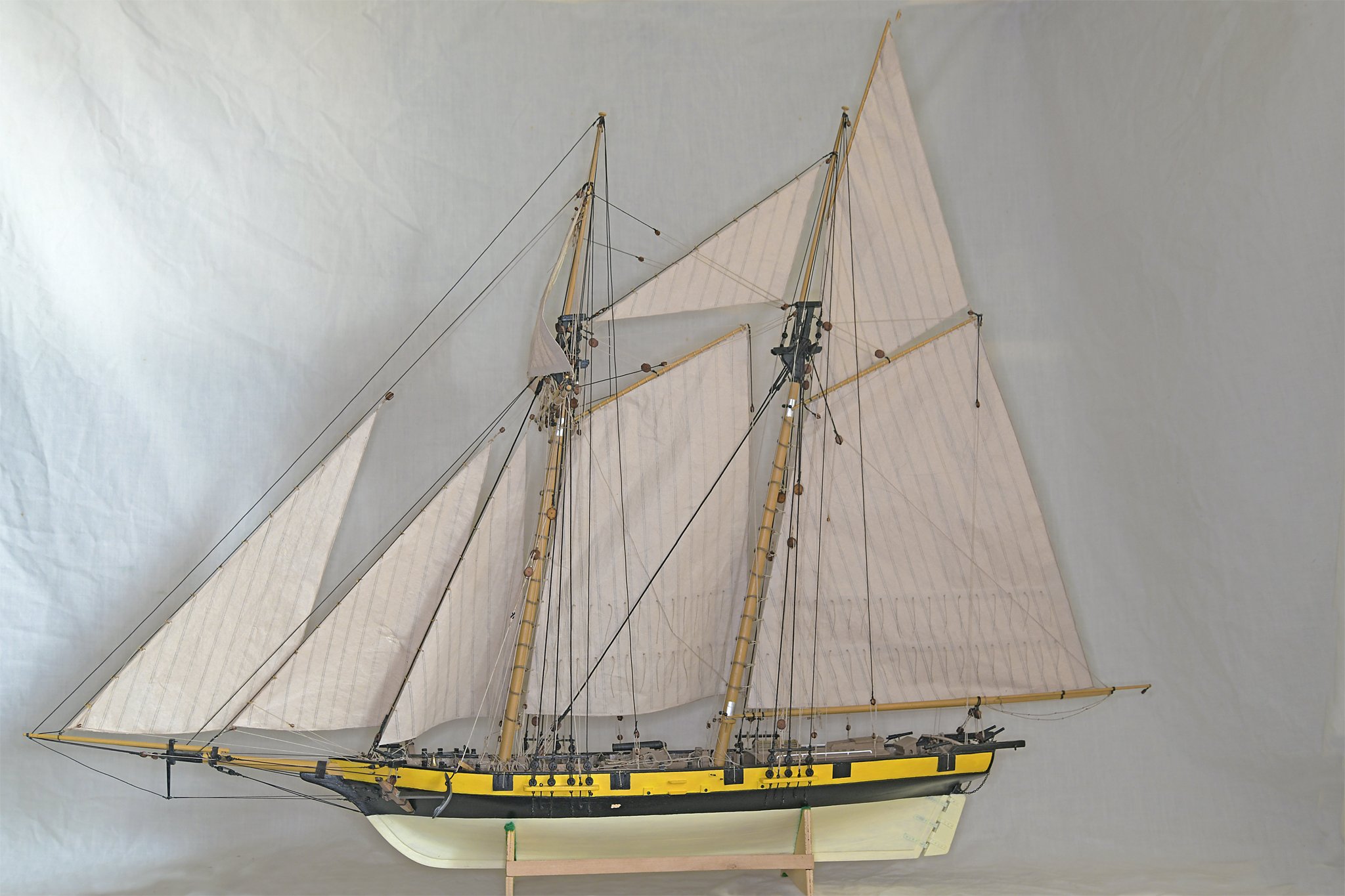
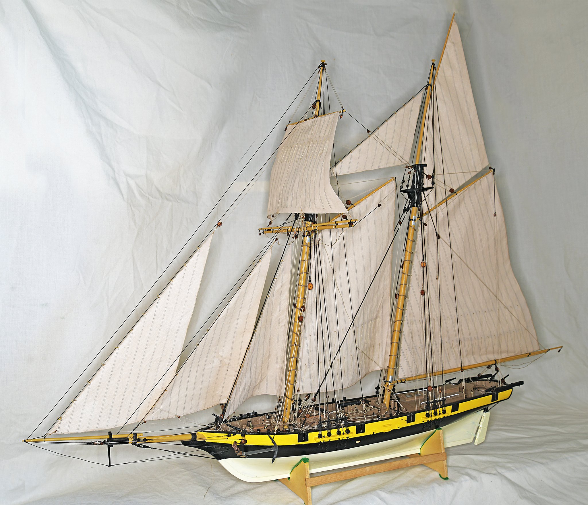
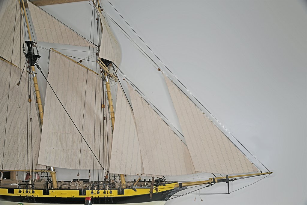
The model is fully rigged (almost) - I think. All of the sails and running rigging are in place. I still have a lot of tidying up to do to trim excess line lengths and add the rope loops to belaying points. But I think all of the lines are in place except the ratlines. The thought of tying thousands of knots for the ratlines brings nothing but joy to my heart! One more plastic hook broke. I replaced it with one of my metal hooks. I suspect it will be necessary to tighten some of the lines, but at least the all are in place (I hope)! After that the ships boat will have to be added. I have a Vanguard Models 18 foot Cutter kit for the boat.

-
Falconer's Universal Dictionary of the Marine (1769) says the lanyards in deadeyes were smeared with hog's lard or tallow so it slips more easily through the holes. Consequently I would suspect that they aren't tarred heavily, But the fat probably oxidized to a brown color, so the lanyards wouldn't look like new rope - unless they were new. He doesn't say anything about rat lines (rattlings) being tarred or not. But they are part of the standing rigging. Since the shrouds were tarred it is safe to assume the ratlines would be tarred also.
-
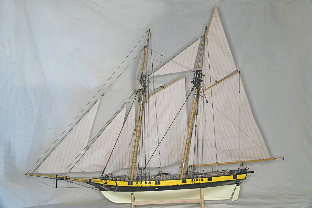
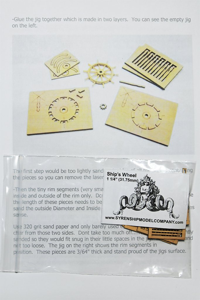
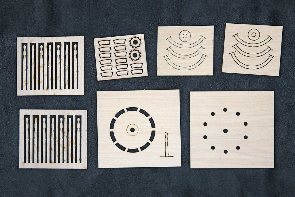
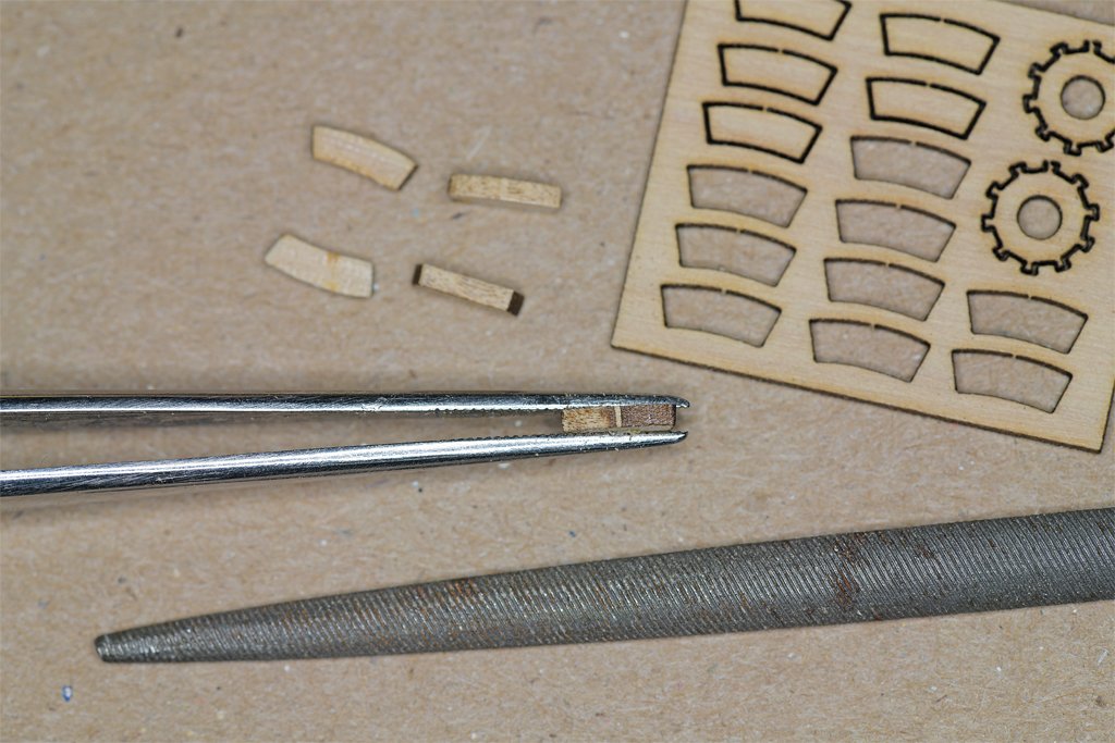
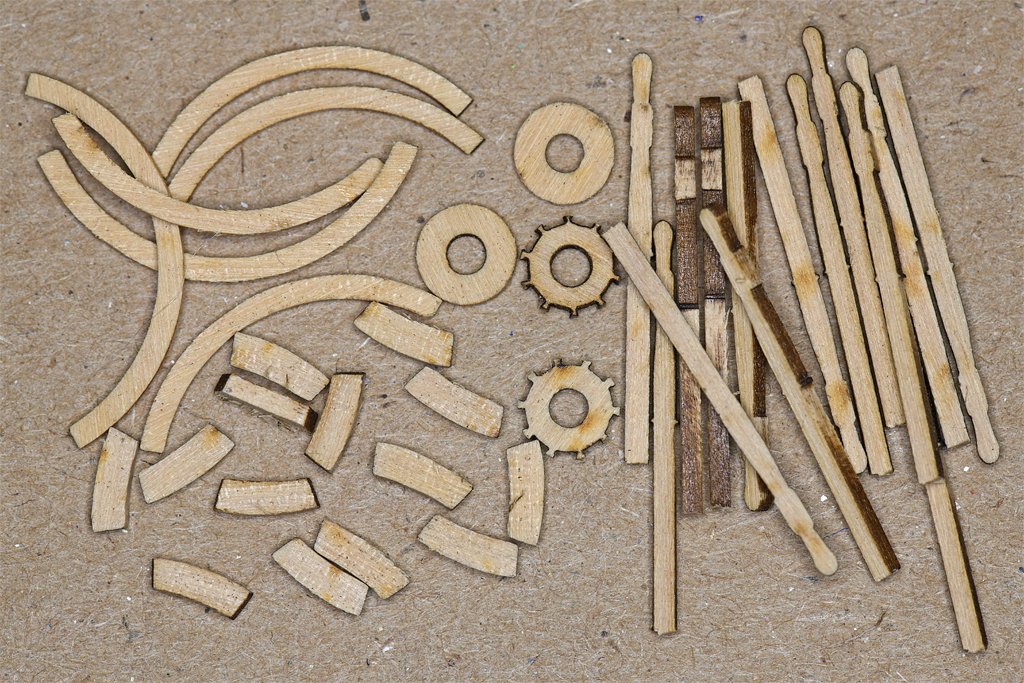
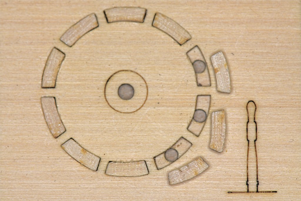
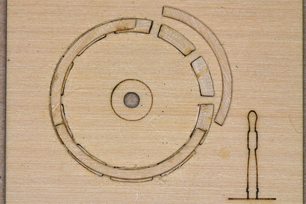
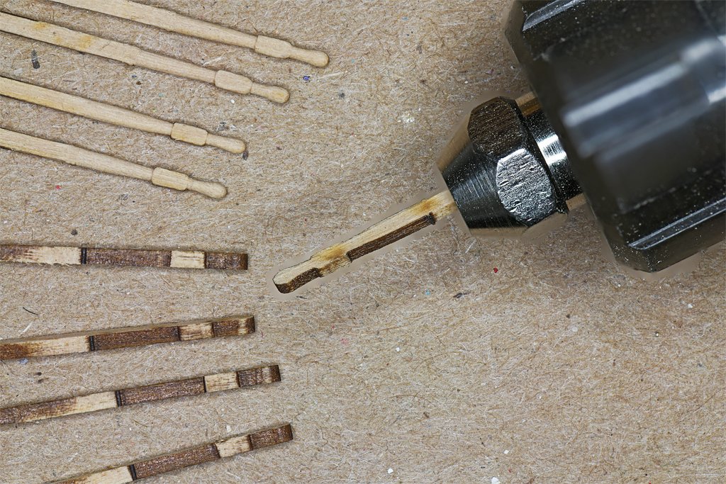
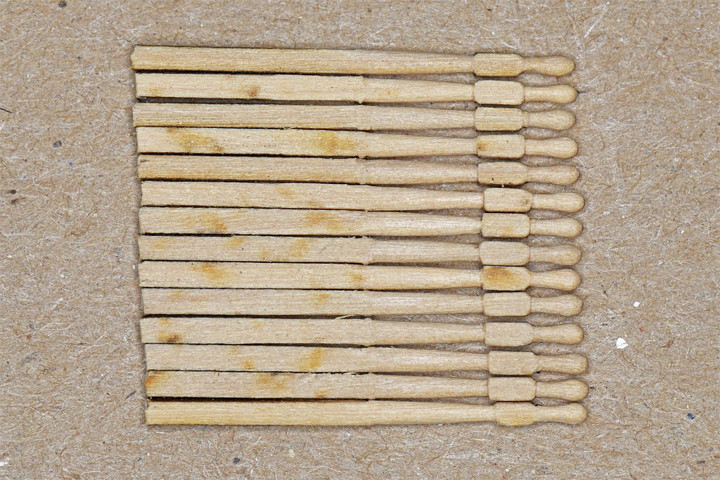
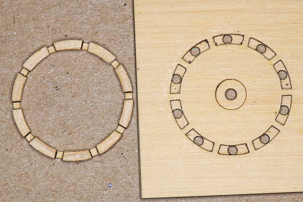
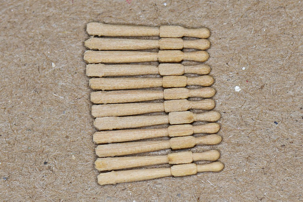
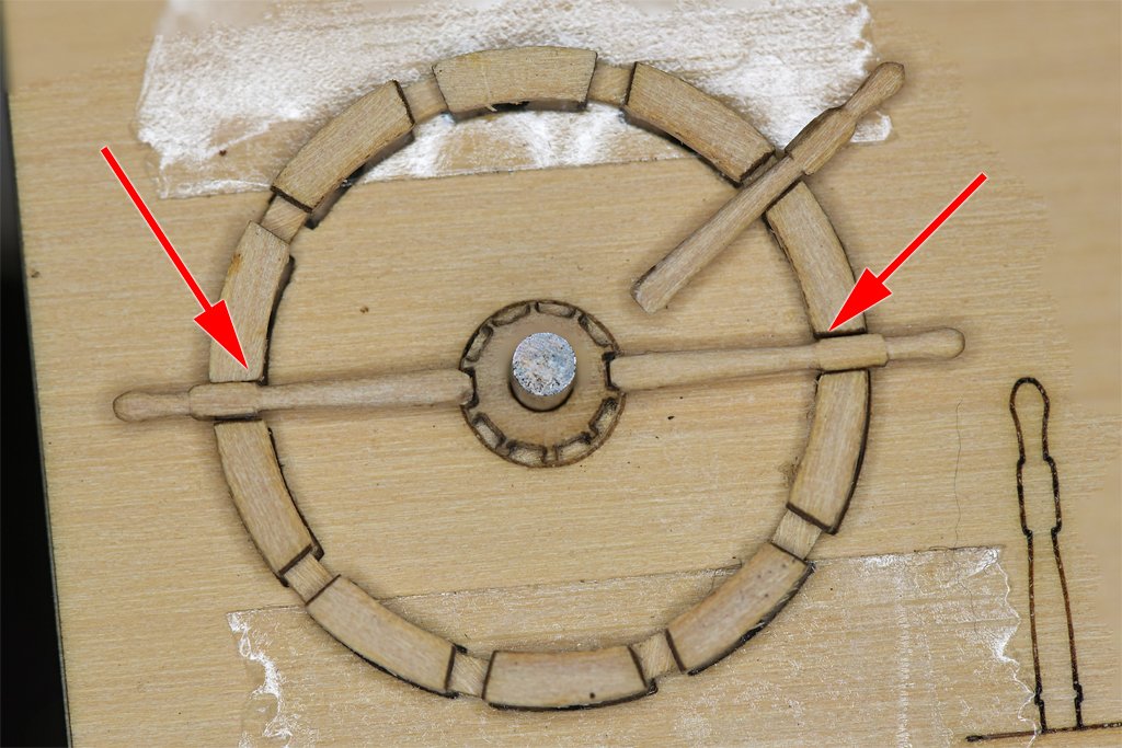
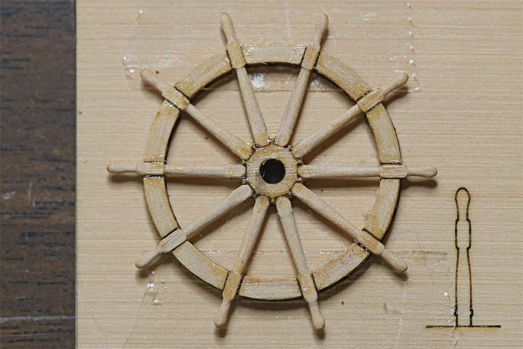
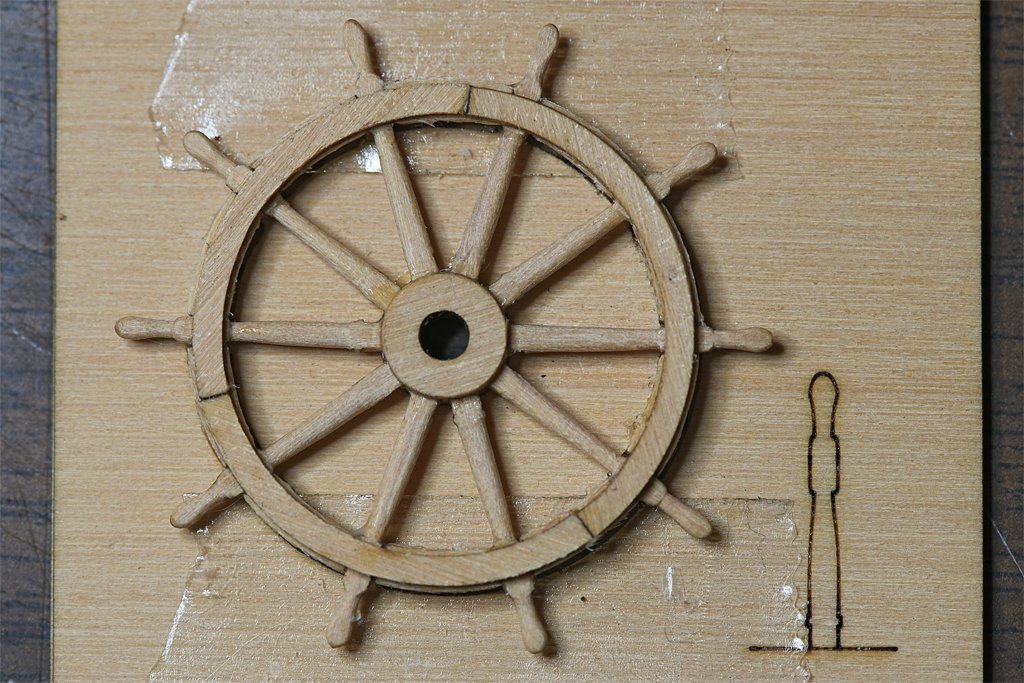
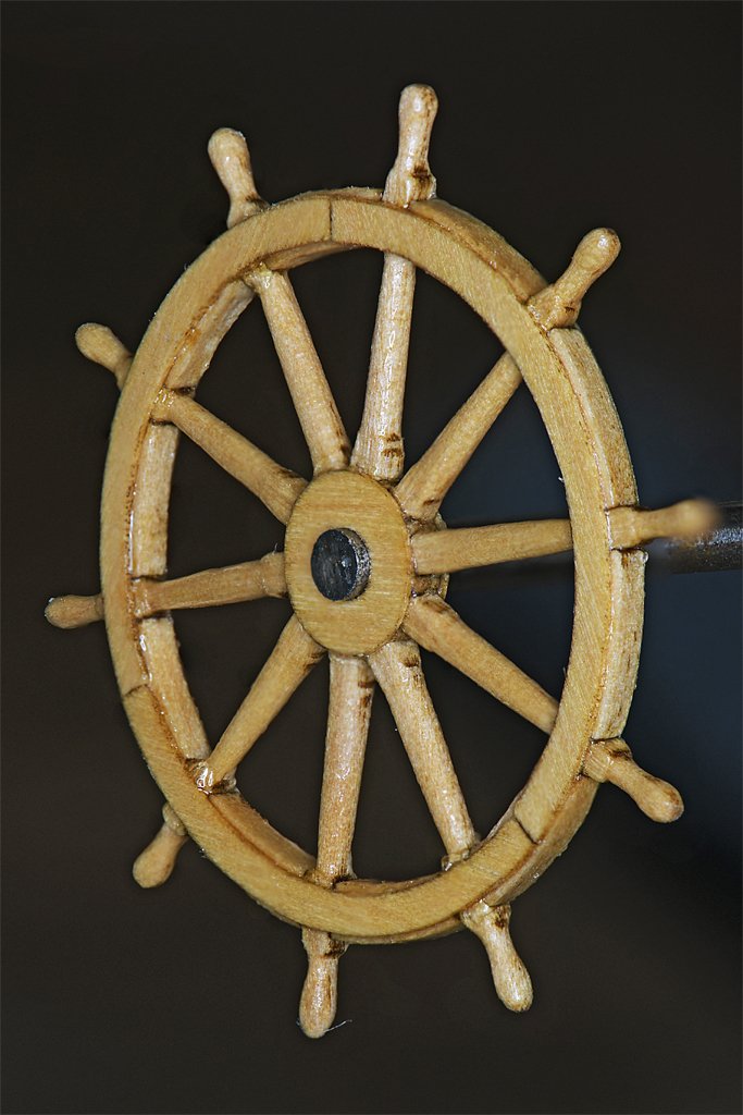
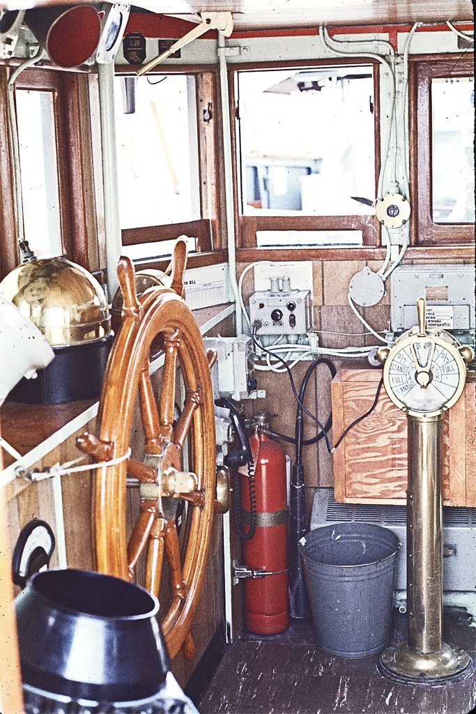
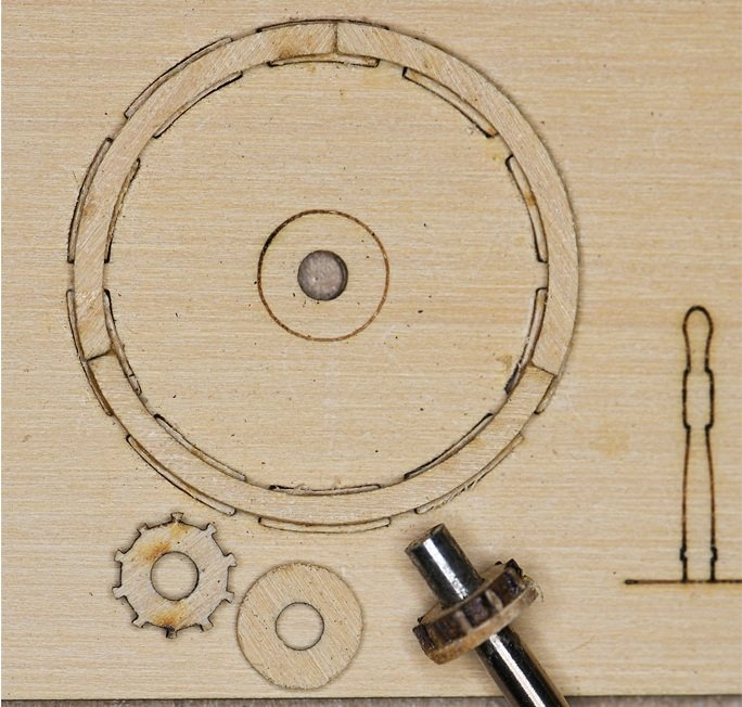
It has been a while since I updated this log. I have been working to finish the rigging on my topsail schooner build, and that has been very time consuming. I had to order more rope for that job, and also ordered a helm (ship's steering wheel) for the Cape's pilot house. I considered carving one from scratch, but noticed that Syren had two "mini kits" for ship's wheels, 15/16 inch (26.34 mm) and 1 ¼ inch (31.75 mm) diameter. The kit wheels are ten spoke wheels, and the Cape's wheel had eight spokes. I originally estimated from the pilot house photo that the wheel was about 4 ½ feet diameter. So the 1 ¼ inch wheel would be closet. But I have since found a blueprint that says the wheel was 48 inches diameter – 1 inch at 1:48 scale. So this wheel is a bit oversized. But only the top will be visible in the model's pilot house, so this is good enough! If I had the proper tools I might try making a wheel, but the Syren kit is a lot simpler, and can be finished faster. So I decided to order the Syren kit and see how it works out. Here is a build log for the Syren 1 ¼ inch Ship's Wheel kit. The kit comes in a small plastic bag with seven small pieces of laser cut Castello Boxwood and a kit label. You must visit the Syren web site to get the instruction sheet PDF file. The instructions caution to not use CA (cyanoacrylate) glue for assembly. It sets too fast, and you need to be able to align parts before the glue hardens. Syren recommends water soluble yellow glue. I used Sig-Bond aliphatic resin. The instructions say to sand all sheets lightly to remove laser char. These are solid wood sheets, not plywood, and they have grain. If you bend the thin sheets along the grain they will break. Handle with care! The two largest sheets must be carefully aligned and glued together to create a jig for the wheel assembly. The ten round holes in the bottom sheet should line up in the center of ten arc holes in the top sheet. I used the shank of a 3/32 inch (0.094 inch, 2.4 mm) drill bit to align the center holes. Next you should remove the "rim segments" – the short arc pieces – and carefully sand or file the curved edges to remove char. The short end sides should not have the char removed so they will fit tightly in the assembly jig holes. The instructions suggest using 320 grit sandpaper and sanding lightly to remove char. I used a small "D" cross section file and used very light pressure. I used tweezers to hold all of the small pieces firmly while removing the char. Some of these parts are only 0.025 inch (0.6 mm) thick and fragile. By filing only where the tweezers hold them I avoided bending the parts. Even so, I did break off a bit of one of the "C" shaped pieces, but it glued back together nicely with Duco Cement. It didn't take long to remove the char from all the parts. Extra pieces are included for the rim segments and spokes in case you lose or break one. The next step was to place the rim segments into the positions in the jig. Here you see seven of these pieces in the holes in the jig, and three more waiting to be placed. They are not glued! I found it necessary to file the curved sides a bit to remove all of the char before the pieces would fit into the jig. The rim segments are thicker than the jig piece and stand proud. Next the ring "C" pieces were glued to the rim segments. You must use glue sparingly, placing a small drop on the rim segments to ensure that you don't glue anything to the jig. Clean up any glue that squeezes out. Here two ring pieces have been glued in place and the third is waiting. Position these carefully over the rim pieces so a bit of the rim segments shows on both sides. I used Sig-Bond aliphatic resin to glue the parts together. It is slow setting and that allowed me to center the ring pieces on the rim segments. I allowed the glue to set several hours before working with these pieces. Next the wheel hub was made by gluing a "star piece" to a circular disc. I used the 3/32 inch drill bit as a mandrel to ensure that the pieces were centered correctly. After the glue set I scraped the char from the star piece. I probably should have done this before gluing the pieces together. Any glue that squeezed out was removed. After the glue had set the wheel rim was removed from the jig. To do this I pushed through the holes from the back of the jig, one at a time gently until the ring was free. The wheel spokes will fit into the gaps between the rim pieces. The "C" pieces are very thin and will break if you put too much force in any one position. Work slowly and work the piece free a bit at a time. After it is free from the jig you can sand both sides of the ring to make them smooth. The wheel spokes have square cross sections when removed from the sprue. The instructions say to remove the char from the square parts that fit into the ring and the hub, but leave the char on the parts that need to be rounded. This makes it easier to see the places that need to be rounded, and those that should remain square. I used a motor tool to spin the spokes and the D cross section file to turn the parts between the ring and hub. The handles on the ends of the spokes were also fashioned with the file. The instructions say to turn all fourteen of the spokes provided with the kit before trying to place any on the ring and hub. You will get better at it as you go, and afterward you can select the ten best spokes to use in your ship's wheel. You can see where the file slipped on the bottom spoke and rounded the edges of the square segment close to the handle. Another spoke has a handle that is too large. Next the spokes must be trimmed to length. The jig has a pattern that can be used to trim off the extra material. The ends that fit into the notches in the star piece of the hub need to be filed to a "\_/" blunt point shape to fit All of the pieces need to be the right length so the square cross section pieces fit between the ring and the hub. This was the most difficult part of the build. I used the drill bit to center the hub on the jig. The holes in the jig were used to align the ring centered on the hub. Double sided tape held the ring in place while each spoke was trimmed to the same length. The spoke on the right is trimmed so the square section at the ring aligns on the inside with the edge of the ring. The piece on the left is a bit too long, so the inner part of the square section is too far out from the hub. I filed some off of the hub end until it was the correct length. With all the spokes the correct length it was time to glue them to the hub and the ring. Again, it was necessary to be careful that the ring, hub and spokes were not glued to the jig. For this job I used Duco Cement. It makes a good bond between wood pieces and takes a bit longer than CA to set so the pieces can be repositioned as necessary. After the glue set the surface was sanded smooth. Next the remaining "C" pieces were glued to the ring. I used Sig-Bond glue for this. The "C" pieces must be positioned carefully to be centered on the rim pieces. After the glue set the wheel was carefully lifted from the double sided tape. Then both sides were sanded with 150 grit paper to reduce the thickness of the "C pieces to about 0.012 inch (0.3 mm). Then they were finished with 220 grit sandpaper. The resulting wheel looks pretty good! I put a layer of shellac on it, and may follow up with more to darken it a bit. There are a few places when some of the char is still visible, and this probably should be filed off. If I had a lathe I might have turned some knurls or rings on the spokes like on the Cape's wheel. But I wasn't going to attempt this using a motor tool and a file! The original wheel had some brass parts around the hub. I am not going to try this at 1:48 scale. Now I just need a pilot house to put it in!
- 484 replies
-
- 20
-
-

-
- minesweeper
- Cape
- (and 1 more)
-
Paul, You are planking the hull from the inside out! That is a very good way to get all the bulwark frames in place. I envy you on this build. The HAER report drawings show so much detail of the construction of the ship. We don't have that detailed information for most builds. Somewhere here I should have photos (slides) I took on the Wapama back in 1972 when I was in San Francisco for discharge from the Navy. If I find them I'll scan them and send them to you.
-
Question re: Rigging Multiple Blocks at One Location
Dr PR replied to GGibson's topic in Masting, rigging and sails
Greg, Here is a bit of terminology. The yard is the spar the sail hangs from. The tapered end where all these lines and block go is the yard arm. Ya gotta know this stuff if you want to talk like a pirate! -
One less plastic hook on the model. The crash also broke the hook on the top block of the main gaff peak halliard luff tackle! One step back. I am repairing it using one of my metal hooks. Another step forward. Look at it this way - all those broken hooks and failed seizing just lets me have the pleasure of doing the rigging again! Thank you Murphy!
-
Question re: Rigging Multiple Blocks at One Location
Dr PR replied to GGibson's topic in Masting, rigging and sails
Take a look at this post: https://modelshipworld.com/topic/19611-albatros-by-dr-pr-mantua-scale-148-revenue-cutter-kitbash-about-1815/?do=findComment&comment=1092641 I rigged the blocks at the yard arm pretty much as shown in your drawing and had to go back and redo one of them to allow the lines to run free without tangling and chafing. Each block should be attached to the yard arm separately. I used seizing (small thread wrapped tightly around the ropes) that was glued to the ropes. The outer black rope is the brace pendant with a block stropped (strapped) and seized into the end. This is the lower block in your drawing. It prevents the other ropes/blocks from slipping off the yard arm. But on my vessel the stunsail boom irons hold everything on the yard arms. -
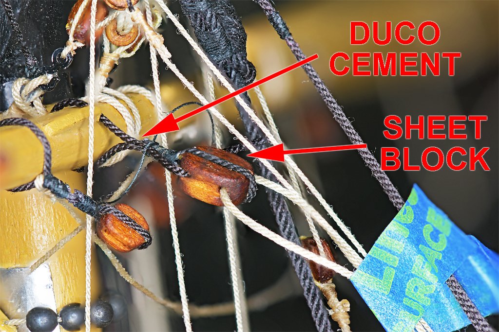
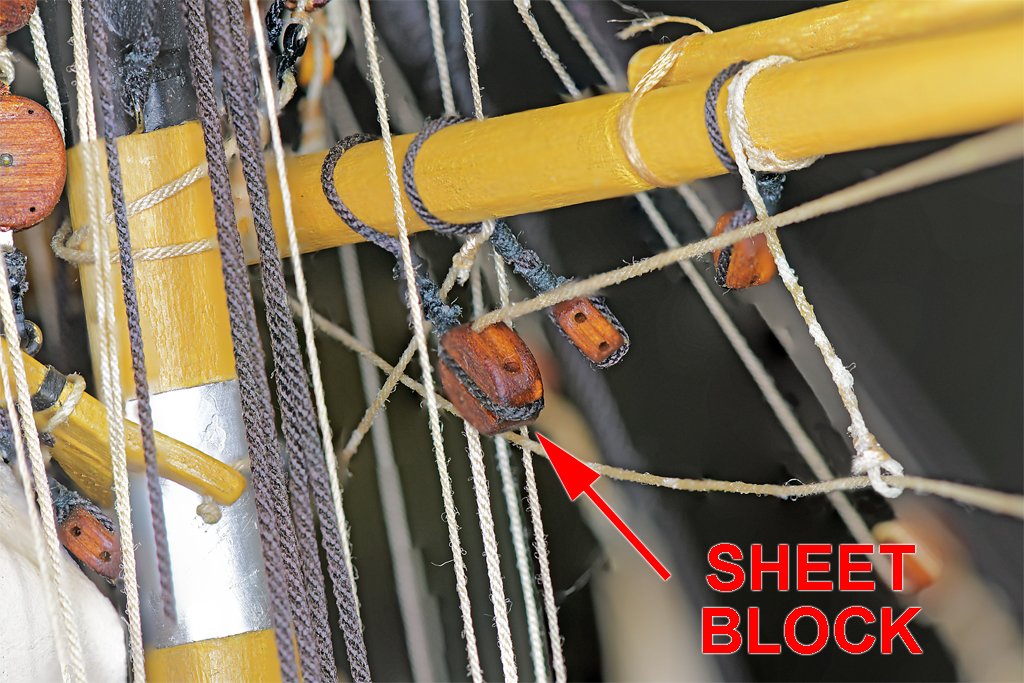
Steve, There are still too many plastic hooks on this model! But take note that they are not failing during the normal rigging process. I don't put a lot of strain on the lines, just enough to make them run pretty straight. The hooks are breaking when I screw up and accidentally put too much stress on the lines. Murphy again! I repaired the sheet block. I wrapped some 0.025" (0.63 mm) rope around the block for stropping and glued it in place around the block with white glue. Then I put a drop of Duco Cement on the two strands and wound some fine black cotton thread around it to create the seizing. After that was set I looped the long end of the 0.025" rope around the fore course yard inside the sling cleats (in the photo at left). I tied a piece of black thread around the rope strands with an overhand knot. Then I put a drop of Duco Cement on the two rope strands and held them together a few seconds until the glue started to set. Then the long end of the thread was wrapped around the ropes to finish the seizing. It was a tight fit! One point in Duco Cement's favor - over CA - is that like the white glue you can loosen the knots easily, but with a bit of acetone instead of water. The sheet rope had a small block seized to the lower end as part of a runner tackle. Since I couldn't pull this through the sheet block the sheet rope was pulled back and held out of the way with blue tape while I made the repair. Then I discovered that the sheet rope was wrapped around the footropes on the yard and one of the other ropes descending from above! I had to remove the lower block from the end of the sheet rope and reroute the line through and around the rats nest of ropes around the mast top. Of course, I had glued the lower block strop seizing with Duco Cement, and it didn't want to come undone. But the strop was glued with white glue where it passed around the block. A little water on the strop to loosen the white glue and I was able to pull the block free. Then I had to soak the seizing in acetone to dissolve the Duco Cement. After a while the seizing came off and the rope end was free. I didn't want to wet the block with acetone because the dye that I used to stain the block might wash out. After rerouting the sheet rope the lower block was attached again - with Duco Cement to ensure that the seizing doesn't fail. This photo shows the repaired block, with the sheet rope threaded through and around the other lines so it descends to the runner tackle belayed to an eye bolt on deck and a pin on the fife rail at the base of the mast. In the process the course yard creeped up on the mast again. It should be just at the top of the metal shield for the gaff jaws. Now I will need to readjust all of the lifts, sheets, buntlines, trusses and braces to get it back down again! Maybe Murphy's Folly would be a good name for the ship.
-
Thanks for the encouragement guys! The irony in this last goof-up is that I was trying to get a better picture of the outer jib. I was using a white dry erase marker board as background and the shiny surface was reflecting the ring light. So I repositioned the board, and as I stepped back to take the picture the board fell over against the model. Fortunately I was still close enough to catch things before the model took a dive to the floor! Otherwise I might be thinking about reconstructing a lot more of the masts and rigging! So Murphy didn't have the last say! And I relearned a lesson that I have learned far too many times in the past - pay attention to what you are doing! **** The model kit was titled "Albatross" but I can find no record of a real vessel with that name. And since I am building a model of an imaginary 100 ton revenue cutter of the early 1800s I have been reluctant to give the model a name. That might imply that it is a model of a real vessel. But now I am thinking of calling it Murphy's Jest or something like that! Murphy's Joke Murphy Bait Murphy's Taunt Murphy's Fun ????
-
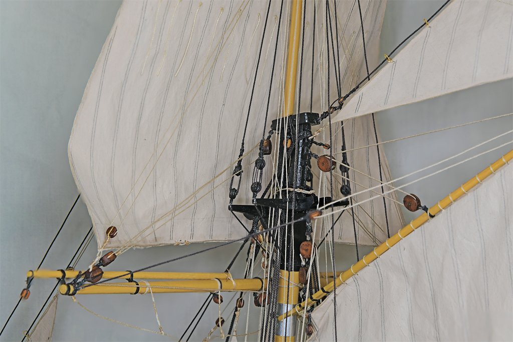
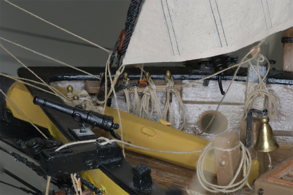
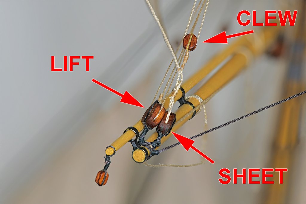
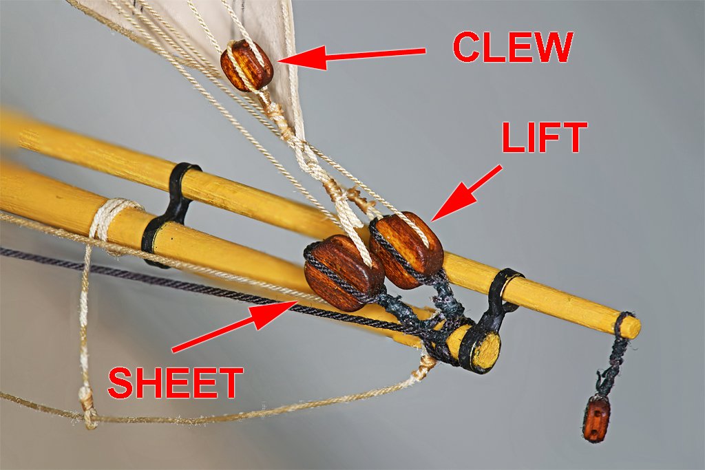
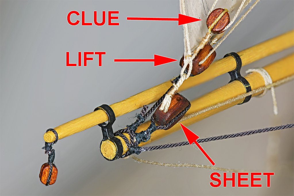
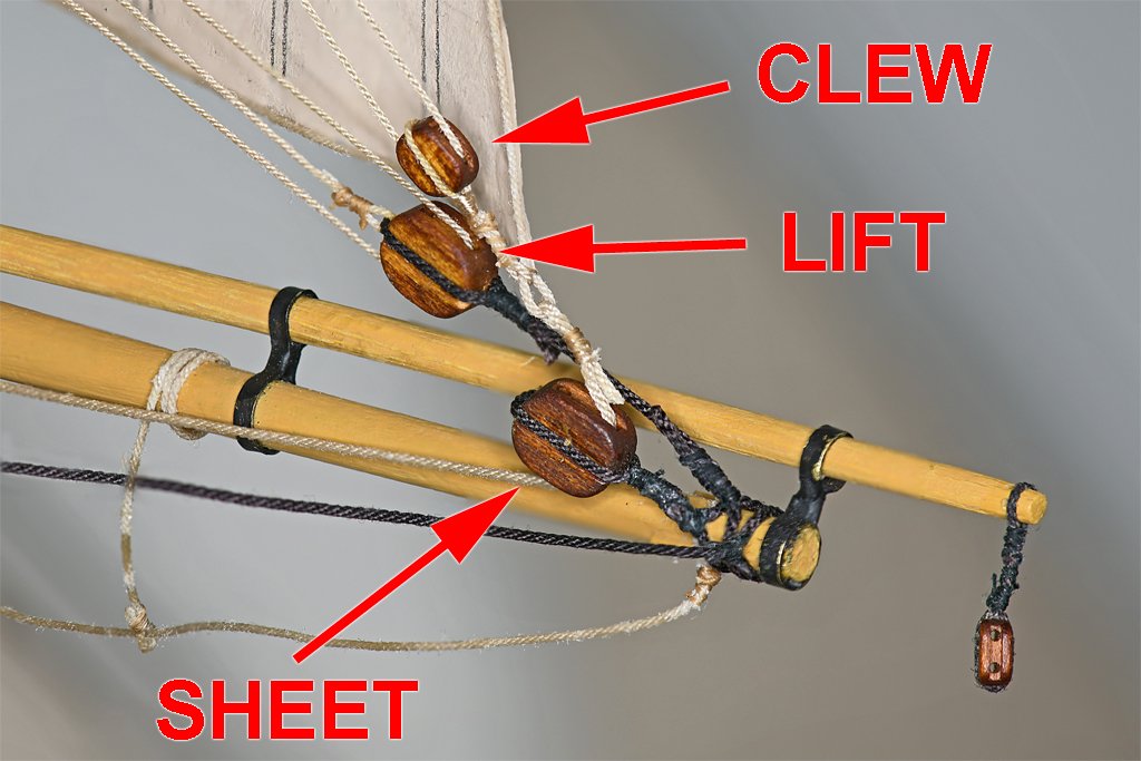
I have been thinking abut a problem that developed as I was adding the fore topsail to the mast. You can see it in these pictures. The lift blocks and sheet blocks were jammed together, and the lift lines were rubbing against the sail clews and the clew blocks. It looked OK "on paper" but just wasn't right after the sail was installed. The sheet block was in the correct place, with the sail clew and clew line block OK. I decided to remove the lift blocks and give them a longer pendant. But I had to do this in place, and things were a bit crowded. Some vessels used a sister block or "violin block" with the lift running through the inner sheave and the sheet in the outer sheave. And in some cases the two blocks were just stropped together end to end to keep the two lines separate. Now the lift blocks fit under the clew of the sail and the sheet is free to run naturally. It wasn't as much trouble as I thought it would be. But Murphy did get in his licks. While removing the old lift blocks the plastic hook on one of the double blocks at the mast top broke! I replaced the plastic hook with one of my metal hooks and the repair was finished. One step back, one step forward. All of this happened while I was installing the outer jib. That was the last sail! Like the other fore sails the sheets are still hanging loose. But the rest of the rigging is in place! Two steps forward. The nomenclature for this sail is a bit confused. Some authors call it the outer jib, but others call it the flying jib. However, the term "flying" sometimes means a sail is not attached to a stay, but is hanging only by the halliard and tack. But there are many references showing a sail that is riding on a stay but is called a flying jib anyway. Likewise the main sail is sometimes said to be flying if there is no boom, and in other books is is flying it it is attached to the boom only at the tack and clew, without being laced to the boom. This is also called "loose footed." So the term "flying" seems to mean different things to different authors. With the installation of the outer jib almost all of the rigging is installed. Most of the lines are belayed and only a few need to be adjusted. The belayed ends are still a couple inches long to allow them to be adjusted, so the deck looks like a bowl of spaghetti. But most of the work was done! And then the backdrop I was using for this last photo fell over and hit the model! The blow caused the seizing to fail on the starboard sheet block attached near the center of the fore course yard! It was in one of the most inaccessible places in the rats nest of rigging just under the fore top. One giant leap backwards! Murphy was busy today!! If there are any newbies following this log keep this in mind. If it can go wrong it will go wrong!
-
Actually, the trick is to cut the garboard strake so the next plank runs pretty straight to the stem (bow). The lower edge of the garboard strake follows the rabbet at the keel. curving up at the bow. The upper edge of the garboard strake should follow the unmodified edge of the next plank as it curves around the bow. Each additional plank follows the same rule. The lower edge follows the curve of the plank below it, and the upper edge is trimmed to follow the curve of the plank above it. So one edge of each plank is the natural curve around the shape of the hull, and the upper edge is trimmed to fit the plank above it. While this sounds simple, it may be necessary to "hook" planks above and below a plank, cutting it short and hooking the planks above and/or below to fill in the space. Look at the tutorials.