
HOLIDAY DONATION DRIVE - SUPPORT MSW - DO YOUR PART TO KEEP THIS GREAT FORUM GOING! (89 donations so far out of 49,000 members - C'mon guys!)
×


Dr PR
-
Posts
2,441 -
Joined
-
Last visited
Content Type
Profiles
Forums
Gallery
Events
Everything posted by Dr PR
-

Atlantic by Bluejacket rigging question
Dr PR replied to bruceh's topic in Masting, rigging and sails
Bruce, Nice model! All ropes/threads made with spiral strands will have a built in twist. When you pull on them the rope stretches and unwinds. In the period instructions for rigging sailing ships (like Lever's The Young Sea Officer's Sheet Anchor - 1808) some ropes are to be stretched to minimize the twist and subsequent change in length before they are used. I have the same problem on my current schooner build, and there is a simple solution - at least for now. First, don't pull the ropes too tight. This makes the ropes twist. Put on just enough strain to make them hang taut. Of course it is too late to do this on a 15 year old model. Second, find where the twisted ropes pass through a block, like those shown in the first two photos you posted of the gaff peak halyard. Look at the twist the ropes have relative to the block. Then take both strands of the rope (on opposite sides of the block) between your fingers and give them a slight twist to rotate the rope in the hole in the block. This removes the cause of the twist on the block, and that removes the twist on the block pendant. You may have to follow the line down to other places it passes through blocks, fairleads, eyes and such to continue the rotation of the line until the twist is relieved. Where this can go wrong if the line was belayed with a significant twist - or if a bad twist develops at the belayed end due to your twisting the upper parts of the line. If the belayed end is hooked to an eye bolt try unhooking it, untwisting it, and hooking it back again. Three, as a last desperate measure you could put a counter twist in a section of the rope sufficient to relieve the twisting in the rest of the line, and then paint the rope with glue or shellac to "lock" the counter twist in that section. Four, keep your fingers crossed! -
Iro, That is a very nice planking job. I suspect this isn't your first.
-
I have tried several needle threaders and there is no way you can get the wire loop plus two parts of the ropes through the holes in the smaller blocks. Rope sizes and block sizes are related, and block holes are usually drilled out enough to allow only one strand of rope/thread to pass loosely. I put some Duco Cement (nitrocellulose in acetone) on the tip of the rope as soon as it is cut to prevent it from unravelling. This also stiffens the end of the rope, and it is usually good for threading through blocks. Sometimes on the smallest blocks and ropes I clip the glued end of the rope at an angle to create a "point" and this always goes through the hole in the block. If the rope end is frayed after passing through several holes I trim it back again. I hold the glued end of the rope with tweezers about 1 1/2 block diameters from the end and thread the stiffened end through the block. Then I hold the block with my fingers and pull the rope on through with the tweezers, or in some cases I use a second tweezers to pull the end protruding through the block. However, I always drill out then holes in blocks with a drill bit a size or two larger than the rope/thread. After manufacturing it is common for dust and tiny wood chips to remain in the holes. It is just good practice to clean the holes before using.
-
USS Constitution by mtbediz - 1:76
Dr PR replied to mtbediz's topic in - Build logs for subjects built 1751 - 1800
Mustafa, This is a beautiful model! I really appreciate the research you are putting into it. -
Austin, Thanks. I would appreciate any photos you want to send. The sort of things I will be researching is the planking on the bow forward of the deck house, any evidence of a bell or flag bag on the aft side of the O1 level deck house forward of the funnel, etc. Anything that looks original. And I would like to see what you have done with the open bridge and pilot house. I can't find anything in the blueprints about wooden pegs in the planking, so that might have been done some time after the ship was built. However, I do have a hypothesis based upon the photos you sent. The hull originally had double layer planking for the entire hull, but it had a third layer of 3/4 inch red oak planking from 11 feet above the base line (about even with the discharge ports right above the waterline) down to the keel. This outer layer, or sheathing, was attached with 1 1/2 inch long No. 16 flat head wood screws spaced on 4 1/2 inch centers. These screws have a shaft about 1/4 inch diameter. In your photos I don't see any of this sheathing aft of the section of horizontal planking on the hull at the bow that provides protection from the anchor when it is being handled. It looks like most of this third layer of sheathing has been removed. If so, the screw holes in the remaining planking might have been filled with wooden pegs.
- 464 replies
-
- 8
-

-
- minesweeper
- Cape
- (and 1 more)
-
Keith B, Interesting! The blueprints for the MSI specify zinc protectors, but they were mounted to the wood with phosphor bronze or galvanized brass straps. No mounting hardware through the zincs. And the zincs were to be embedded in zinc oxide paste and caulked all around to keep out sea water. So it looks like they were trying to minimize contact between the zinc and wood. I guess the zincs were the "least of two weevils" when it came to deterioration of parts of the ship.
-
I am working on a wooden minesweeper model - wooden hull, wooden superstructure, etc. However, it did have non-wooden engines, pumps, plumbing, propeller, rudder, etc. And these metals could have galvanic reactions with salt water. For that reason, there were zinc anodes on the hull around the main water intakes and near the propeller and rudder.
-
Now there's a serious modeler. He's on vacation, but he took his ship model with him!
- 165 replies
-
- 4
-
-

-
- Red Jacket
- Marine Model Company
- (and 2 more)
-
Keith, Are you trying to get into Guinness World Records for applying the most coats of finish to a model ship hull?
-
You might try Duco Cement. This is nitrocellulose dissolved in acetone. It soaks into wood and makes a good bond, and it does adhere to smooth surfaces pretty well. Of course you want to use small amounts and place them away from the window openings. The warnings on the tube say to not use it on polyethylene or polypropylene plastics, but doesn't warn against use on acetate. But I expect it will craze the surface - that should make it adhere better.
-
I always put a ruler scale in my drawings that need to be printed at an accurate scale. Some printers just do not print at the desired scale, so setting the size to 100% doesn't help. I had a HP printer that always printed undersize so I printed some test sheets to determine the error. After that I set the scale to 1.094 % and the prints came out correctly. On the other hand I have a Brother printer that prints exactly 100% when I disable the "fit to paper" option in the driver.
-
Keith, I just had the hull sitting on the support stand but otherwise free to move. I doubt I could have put on the tape without moving it. So I put my left hand on the deck and pushed down to hold the hull in position and lightly drew the pencil marks. This is one situation where a hull stand that clamped the keel securely would have come in handy. I may have to do this again to mark the bottom of the boot topping after the new planking layer is added. However, I may just be able to take the center of the third plank down as the bottom of the boot topping. The boot topping should be 3/8 inch (9.5 mm) high, or 12/32, and the planks are 5/32 inch wide. So 2.5 planks will be 12.5/32 (9.9 mm).
- 464 replies
-
- 5
-
-
- minesweeper
- Cape
- (and 1 more)
-
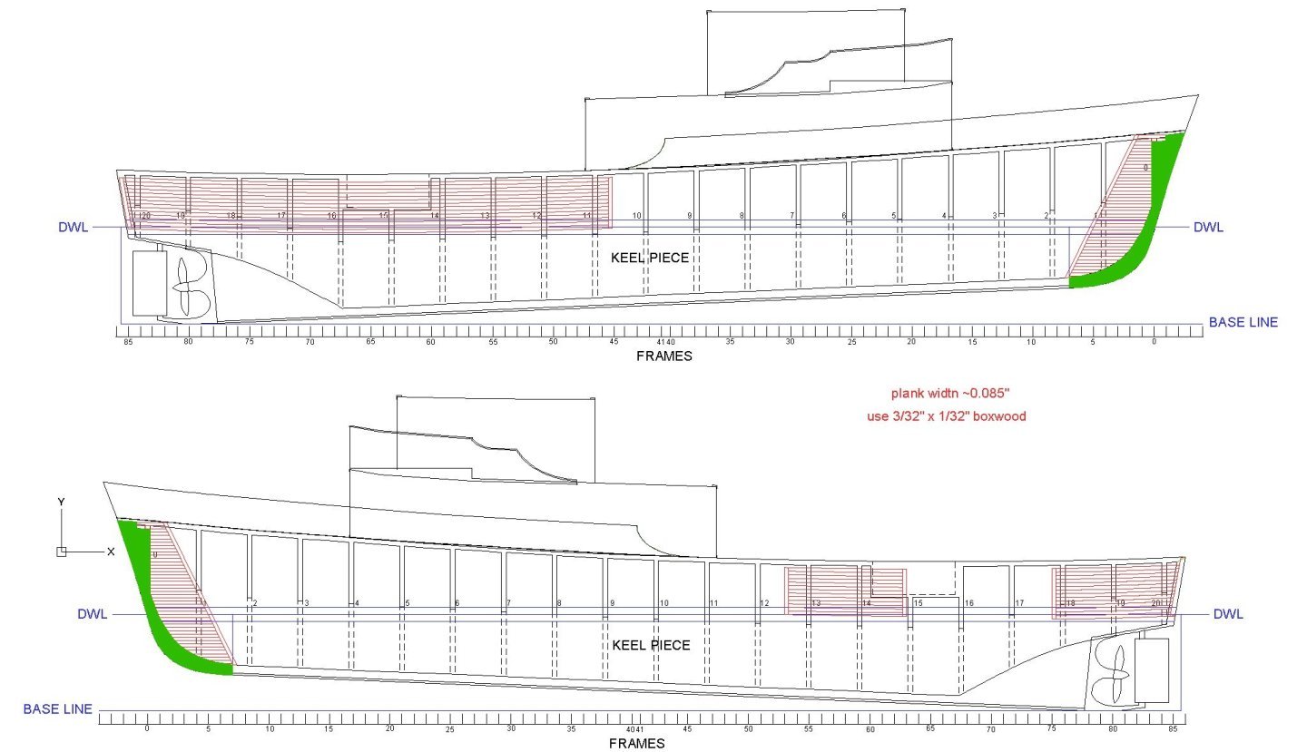
I have a bit of progress to report. That third layer of planking on the ships extended from the keel up to 11 feet above the Base Line (a horizontal reference line for length, height and breadth when designing the vessel). That is also about the level of the top of the black boot topping (water line). In trying to decipher some of the blueprints to see exactly where the top and bottom of the boot topping should be I came up with conflicting results. One drawing shows the top of the boot topping 9 inches above the 10 foot water line (DWL). But another suggested it was actually at the 11 foot water line, at the top of the third level of planking. At 1:48 scale that is a 1/16 inch (1.59 mm) difference, and that would be noticeable. Another issue was the placement of the hull seachests. Several were also at the level 11 feet above the Base Line. So the new planking will need small cutouts where it would cover half of these openings. But these openings should also be a reference for the top of the boot topping. You can see in this photo two of the seachests that are at the 11 foot level. And they are quite clearly at the same level as the top of the boot topping. Several other photos show the same. At 1:48 scale the boot topping is 3/8 inch (9.5 mm) wide. So what I needed to do was draw the top of the boot topping at the level of the seachests and then the bottom the appropriate distance below that. OK, now I know where to put the boot topping and the top of the 3rd layer of planking, how was I supposed to mark these lines? In the past I have used some clamps to make a holder for a pencil with the tip the right height above the bench top, and then dragged the assembly over the bench top with the pencil marking the line. But the Cape has a large difference in draft between the bow and stern, so if I placed it with the keel on the bench top the boot topping wouldn't be horizontal. The deck has a lot of sheer, with a short more or less horizontal section over the magtail cable well. I put the hull on a temporary support that I built a while back and used a spirit level to adjust the position in the support frame until a portion of the deck was horizontal as shown in the blueprints. I also checked that several points that were supposed to be equal height above the base line were actually at the same heights with the hull sitting in the support. This put the hull at the proper angle for marking the horizontal boot topping lines. As I said, I have used the pencil in the holder method to mark waterlines in the past, but it always gave me problems on parts of the hull with significant slope or curvature. And the boot topping actually curves far under the stern of the Cape, especially on the bottom of the boot topping. This time to mark the positions of these lines I used a laser level (Bosch GLL50-20) mounted on a tripod. The laser is indifferent to the angles and curvatures of objects, and illuminates a perfectly horizontal line. After checking to be sure the laser line was at the right height both forward and aft, I used a pencil to draw short dash marks about every half inch (12 mm) along the laser line. Then I stretched some masking tape along the dashes, and drew an ink line along the edge of the tape. As you can see in this next photo the upper line runs through the hull seachest openings that are 11 feet above the base line. You can also see the significant sheer the vessel has at about midships. The top of the full hull length part of the new planking will start along the upper line of the boot topping and will be planked down to the keel. The five above water parts of the sheathing to protect the hull from objects moving over the side will be planked from the top of the boot topping up to the guard rail along the main deck edge. Because the 1/64 inch (0.016 inch or 0.4 mm) thick planking will be so thin there should be no problems fitting it to the hull, and on the real ship there were cutouts in this sheathing around the seachests, rudder fairing and such so I will not need to change any of the work I have already done. But fitting it over the garboard strake and keel may be interesting.

- 464 replies
-
- 11
-
-
- minesweeper
- Cape
- (and 1 more)
-
Well, I just ordered enough S-Scale 1x10s (0.016 x 0.156 inch, 1/64 x 5/32 inch or 0.39 x 4 mm) basswood strips to plank the hull - again! These are 0.80 x 7.5 inch at 1:48 scale, pretty close to the 0.75 x 7.25 original boards. I ordered the Mt. Albert Scale Stripwood from Fast Tracks https://handlaidtrack.com/?v=0b3b97fa6688 Steve, was your hunch correct? I have a bunch of "micro molding scrapers" from Artesania Latina and one has a 1x4 mm scraper with rounded corners. I was planning on using it to round off the edges of the 1/32 inch boxwood strips to give them the "corduroy" look. I will try it with the 1/64 inch basswood strips. If it works I won't have to mess with the 0.005 inch brass spacer. It probably won't work because the 1/64 inch strips are less than 1 mm thick and will be pretty fragile. If not I may just pull a sharp point along the seam between planks to open them up a bit. In the mean time I may start on the deck planking. But I will have to protect it while I am planking the hull. I also have several more sails to rig on the topsail schooner build. And there is the ship's boat for the schooner!
- 464 replies
-
- 4
-
-
- minesweeper
- Cape
- (and 1 more)
-
Gary, Thanks for the link. I'll check it out. There are also places that make scale lumber for doll houses and such. Brian, Thanks for the tip about the propeller. It is a very nice metal casting.
- 464 replies
-
- 3
-
-
- minesweeper
- Cape
- (and 1 more)
-
I assume you are using the rubber cement to glue the paper templates to the wood (it is a bad choice for gluing the wooden pieces together). Another member on the forum suggested using Elmer's All Purpose Glue Stick. I have been using that and it works OK. It isn't messy - just rubs on. Most of the paper will peel off if you use a blade to lift it. Any glue and paper that remains will sand off easily.
-
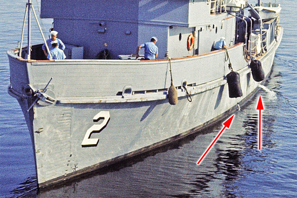
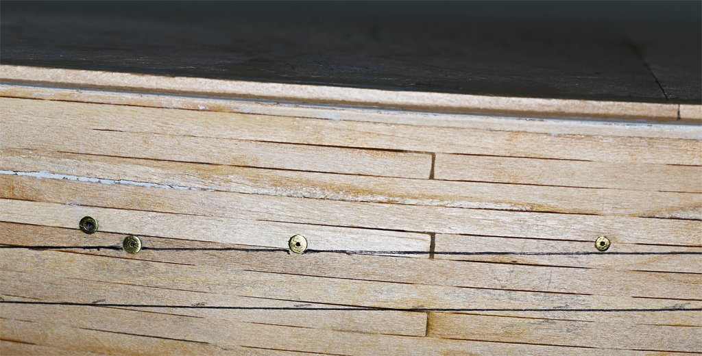
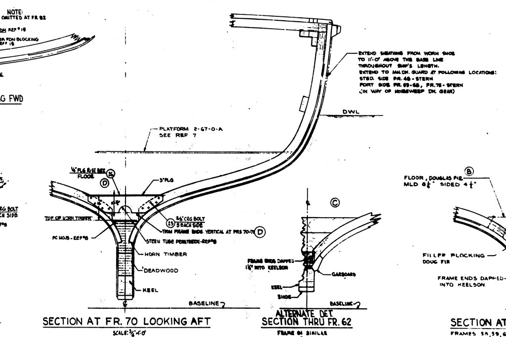
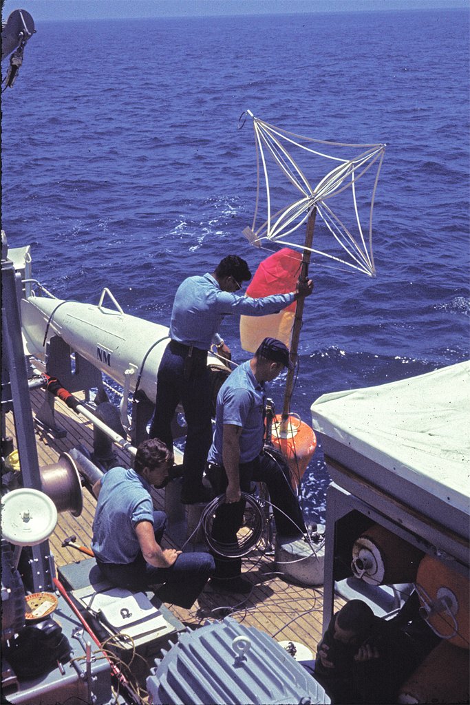
I ran into a snag today. The last details on the hull - before I start on the deck and deck house - are the lining boards. I posted this image earlier. It shows the lining boards in red. These were to prevent chafing and damage to the hull planking when heavy objects were being lowered or raised over the sides. I could see them in photos, but couldn't find them in the blueprints. I have estimated the width from photos but had no idea what the thickness was. I was planning to use 1/32 x 5/32 inch (0.79 x 4 mm) boxwood strips. But today I was looking through the blueprints once more and found this little detail. The small print at the upper right says" Extend sheathing from worm shoe to 11"-0" above the Base Line throughout ship's length. Extend to Mn. Dk. Guard at following locations ..." And those locations are the areas shown in red in the drawing above! I have known all along that the hull was triple planked with red oak sheathing from just above the waterline to the keel. It was only 3/4 inch (19 mm) thick, and that comes out to be 0.016 inch (0.4 mm) at 1:48 scale. I do have 1/64 inch plywood, but I definitely do not want to try to cut several dozen strips 0.151 inch (3.8 mm) from the plywood! I haven't been able to find any 1/64 inch wood strips so I decided to omit this detail. This is an example of a problem working with blueprints. That one short bit of text is on a large drawing sheet with dozens of other details. This is the only place in hundreds of MSI blueprints that the extended sheathing (lining boards) is mentioned. Now what do I do? If I put the lining boards on the hull I really should plank the hull again all the way down to the worm shoe! That would cover just about all of the hull that I have spent weeks filing, scraping and sanding nice and smooth! If I leave the lining boards off it won't be a very accurate model, and I will know it! And just to make it interesting the blueprints say to leave a 1/4 inch (5 mm) gap between the sheathing boards. This gap wasn't filled, and that is why the linings look like corduroy cloth in the photos. The gaps between the boards were very visible! The gaps would be 0.005 inch (0.127 mm) at 1:48. I could use 0.005 inch brass strips as spacers while I am gluing the boards in place. But where will I find 1/64 x 5/32 inch wood strips? Arrrgghhhh! I thought I was almost finished with the hull! This is getting to be like McHale's Navy again, and that brings us to another Dr Pr's Story Time On one occasion the Cape was sent out ahead of a squadron mine sweeping operation to mark the sweep area. We were pretty much worthless for sweeping mines but we could at least plant a buoy to mark the sweep area. Here you see the crew preparing to drop a Dan Buoy (the orange float around the pole). It had a long pole though the buoy, with a heavy weight suspended on a line from the bottom of the pole. At the top of the pole was a radar corner reflector and a red and yellow "ball." This buoy wasn't made up by the Cape's crew, but was assembled by the Mine Squadron on shore, complete with the anchor line and weight. I suspect they didn't trust us to get it right. I do remember some discussion about the length of the anchor cable, and someone saying that the people who made it knew the water depth, range of the tides and such, and had calculated the necessary length of cable so the buoy wouldn't drift too far away from the anchor point. So we arrived at the sweep area and did multiple visual sightings and radar bearing and ranges to known points on land to be sure we were in the drop spot. The Captain gave the order and the fellows pushed the buoy over the side. It flopped over and floated with the radar reflector in the water! But after a minute or so the buoy suddenly jerked upright in the correct position - and then disappeared under the waves!! The water was pretty clear and we could see the reflector and ball about eight to ten feet (3 meters) below the surface. I may have been a boot ensign with no seafaring experience, but I immediately knew this wasn't right! That reflector wasn't going to be any use because most minesweepers didn't have a sonar. The Cape was indeed a special ship, complete with its 3/4 x 7-1/4 inch red oak sheathing planks spaced 1/4 inch apart just to make building a model more difficult!
- 464 replies
-
- 9
-
-
- minesweeper
- Cape
- (and 1 more)
-
Elia, Chuck's blocks are models in themselves. Glad you got the tumbler problem worked out. Your work on the throat crane is very nice! Looks like you have developed the patience to let the saw do its work! I like the New England fishing schooners. I inherited a Bluenose kit many years ago. It was partially built - only started really - and I have been thinking of finishing it as one of the schooners in Chapelle's American Fishing Schooners. Or maybe We're Here from the movie "Captains Courageous."
-
Bleach (sodium hypochlorite) is your best bet for killing the fungus - we used it in my medical mycology lab to kill the nasties. It was diluted about 1:3 with water. However, what it will do to the old cloth is a question. Do you know what type of cloth was used? If it is silk you have few options. As was suggested above, whatever you use should be tested on a part of a sail that isn't especially noticeable. On thing to remember about fungi (molds) is that they reproduce with spores. These are microscopic "seeds" that are made by the bazillions. Spores are really tough. The only way to kill some of them is steam sterilization (or a blowtorch). If you leave one alive it will eventually germinate and start the problem anew. The fact that you have mold growing on the sails tells me that there is something in the sails that is fungus food. It could be the fibers of the cloth - depending upon the type of cloth. Or it might be some organic compound that was used to color the sails (tea) or perhaps starch that was added to give the sails shape. Starch is just polymerized sugar, and is readily digestible by a lot of critters. After you remove the mold you should wash the sails to remove the mold food.
-
Steve, I think blackening the guns is good advice. If you do coat the shiny pieces, in time the coating will crack or degenerate, allowing the atmosphere to get to the brass. You could get corrosion under the clear coating. However your Prince is a very pretty model that showcases all of the natural woods that you used - and not painted all over to hide the wood. I do think the shiny brass pieces would look nice on that model. But no bets on what it will look like in 20 years.
-
Elia, The .heic photo you posted didn't open. It is best to include the photos directly in your posts. JPEG format is good for this. And welcome back. I like schooners so I will be watching.
-
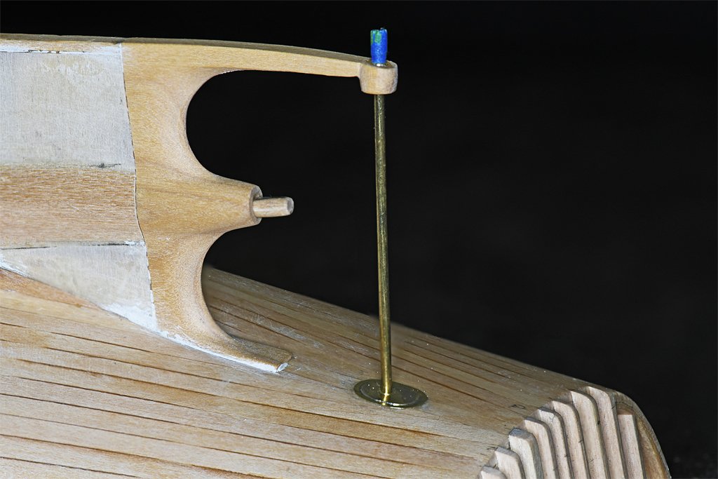
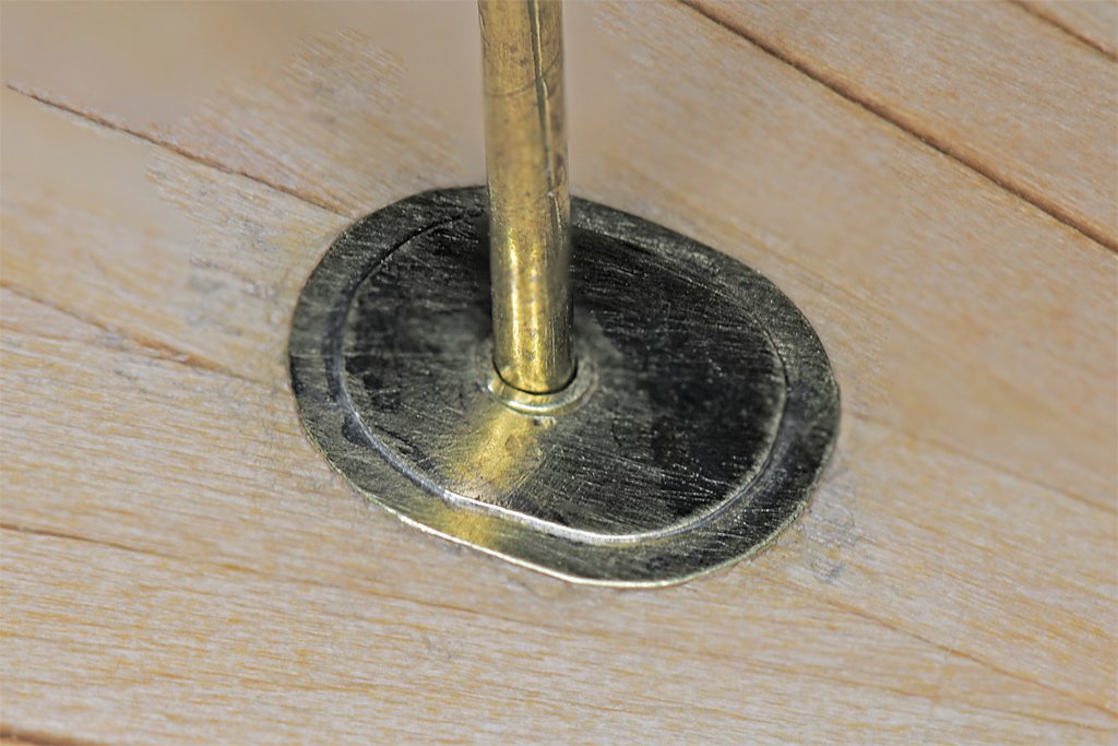
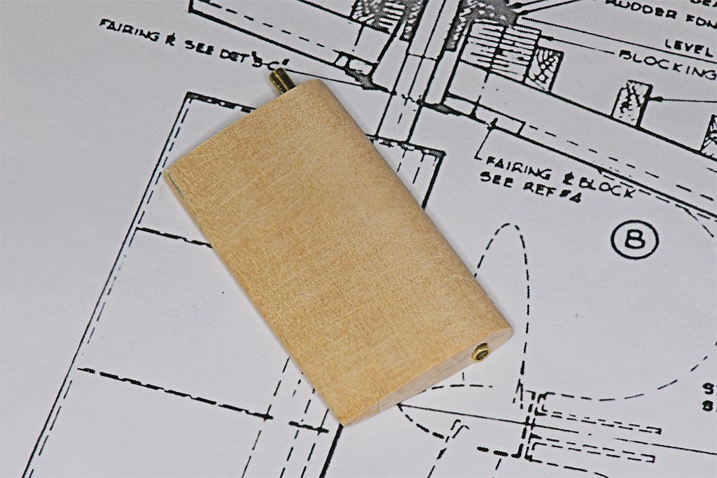
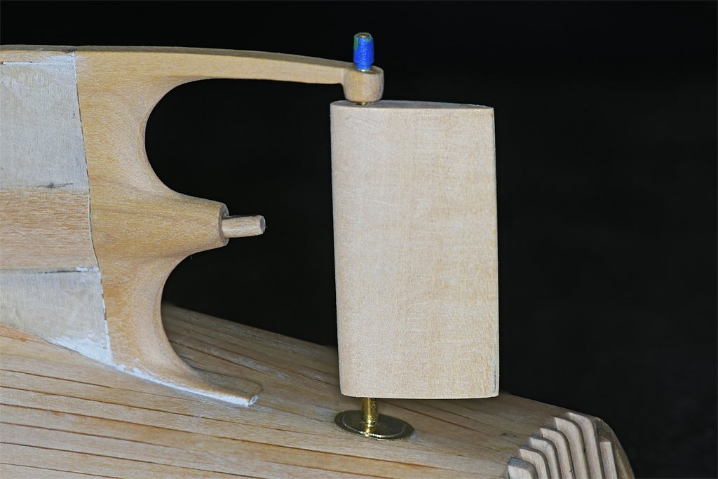
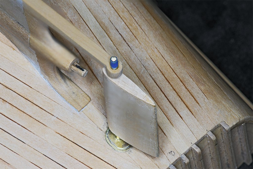
I have been working on the rudder. It is pretty simple but did require some careful work. First I cut and glued short pieces of 3/32 inch (2.38 mm) brass tubing into the hole in the hull planks and the hole in the end of the stern frame arm. These serve as bushings for the rudder shaft, and also as reinforcement for the wood in the stern frame arm. The 1/16 inch (1.59 mm) brass rod slip fits into the brass tubing. The rod is the shaft for the rudder to rotate on. After all the work is finished the part at the end that is wrapped in blue tape will be cut off. The rudder shaft passed through two concentric fairing plates where the shaft opening entered the hull. I cut the two pieces from 0.005 inch (0.127 mm) brass sheet. These were soldered together to make the assembly. The hole in the fairing slipped over the 3/32 inch brass tube and was glued in place with Duco Cement. A thin stainless sheet with a hole slightly larger than the tubing was slipped over the tube. This served as a shield to protect the fairing and hull as the tube was sawed off and the end filed smooth. The rudder was next. Two pieces of 3/32 inch basswood were cut and a groove was filed into each where the rudder shaft should be. They were glued together (Duco Cement) and the glue allowed to harden. Then a series of successively larger drill bits were used to drill out a 3/32 inch hole through the piece. I used a template with the outline of the cross section of the rudder on it to guide sanding the wood into the proper hydrodynamic shape. Then a longer piece of 3/32 inch brass tubing was cut to length to slip fit between the brass bushings in the hull and stern frame. This tube fits through the hole in the rudder and serves as the rudder shaft. But actually the tube just rotates around the 1/16 inch brass rod. The tube through the rudder also serves another purpose. It is a tight fit between the bushings in the hull and on the stern frame arm. It will prevent the arm from being bent up and breaking off if it is bumped. Just a bit of insurance! The 3/32 (0.094) inch diameter tube is actually a bit undersized for the scale rudder shaft. It really should be about 0.110 inch (2.79 mm) diameter. The next larger size brass tubing is 1/8 inch (3.18 mm) and that is a bit oversize. But I think I will cut a short piece to fit over the top end of the rudder shaft and fill the space between the wood and the fairings on the hull.
- 464 replies
-
- 15
-
-

-
- minesweeper
- Cape
- (and 1 more)
-
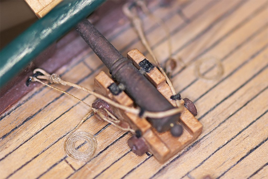
This gun was shiny brass in 1969. It hasn't been polished since. It is on a Billings Santa Maria kit - my first kit build. That is about 55 years of tarnish. If you want the guns to stay shiny spray them with clear lacquer or varnish.
-
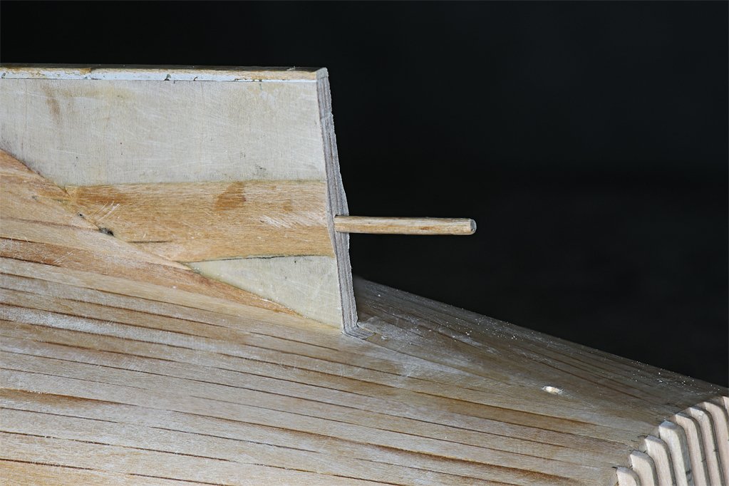
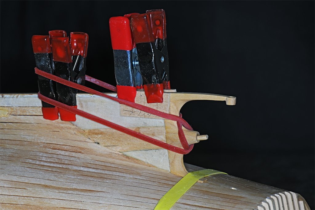
Thanks John! But here is something lovelier ... I have been test fitting the stern frame and I drilled the hole for the prop shaft. I started with a small diameter drill and carefully made the hole through the piece. Then I used successively larger drills to expand the hole to 1/8 inch (3.175 mm). Then I clamped the frame onto the hull and drilled the hole for the prop shaft into the keel/piece. To do this I made short pieces of 0.0925 inch (2.34 mm) and 0.125 inch (3.175 mm) diameter brass tubing. The one slips inside the other, and they fit inside the 1/8 inch diameter hole for the prop shaft in the stern frame. Then I used a 1/16 inch (1.59 mm) drill to start the hole - it just fits inside the smaller diameter brass tube. This produced a pilot hole in the keel piece aligned with the prop shaft axis. Then I removed the smaller piece of brass tubing and used a used 3/32 inch (2.38 mm) drill to enlarge the hole. Then the larger piece of brass tube was removed and the hole in the stern frame guided a 1/8 inch drill to finish the hole for the prop shaft. The photo on the right above shows the stern frame fitted over the prop shaft. The prop shaft is a 1/8 inch wood dowel, and it will serve as a peg to align the stern frame to the keel piece and strengthen the bond between the two. The hole in the hull below the arm on the stern frame is for the rudder shaft. The lower end of the rudder shaft will pivot on the arm of the stern frame. This is what is worth celebrating! I have glued the stern frame onto the hull. I have been dreading this because there are so many opportunities for screwing up! But actually it hasn't been all that bad. The Castello boxwood carved easily and it didn't take as long as I thought it would. And drilling the properly aligned hole for the prop shaft was fairly easy. The biggest hassle was filing down the "foot" of the stern frame that rests on the hull planks. I made it about double thickness and spent a couple hours filing it down to get the right fit on the hull. I guess that was the "worst" part of it all. The boxwood is pretty strong, but I worry about that long arm of the stern frame hanging out there just waiting for me to drop the hull or bang it against something to break that part. After I have finished shaping the stern frame piece I will clamp some strong pieces of wood along the sides to protect it. Brass would have been a better material for the stern frame but I just don't have the tools to do it correctly and in a reasonable amount of time.
- 464 replies
-
- 11
-
-
- minesweeper
- Cape
- (and 1 more)
-
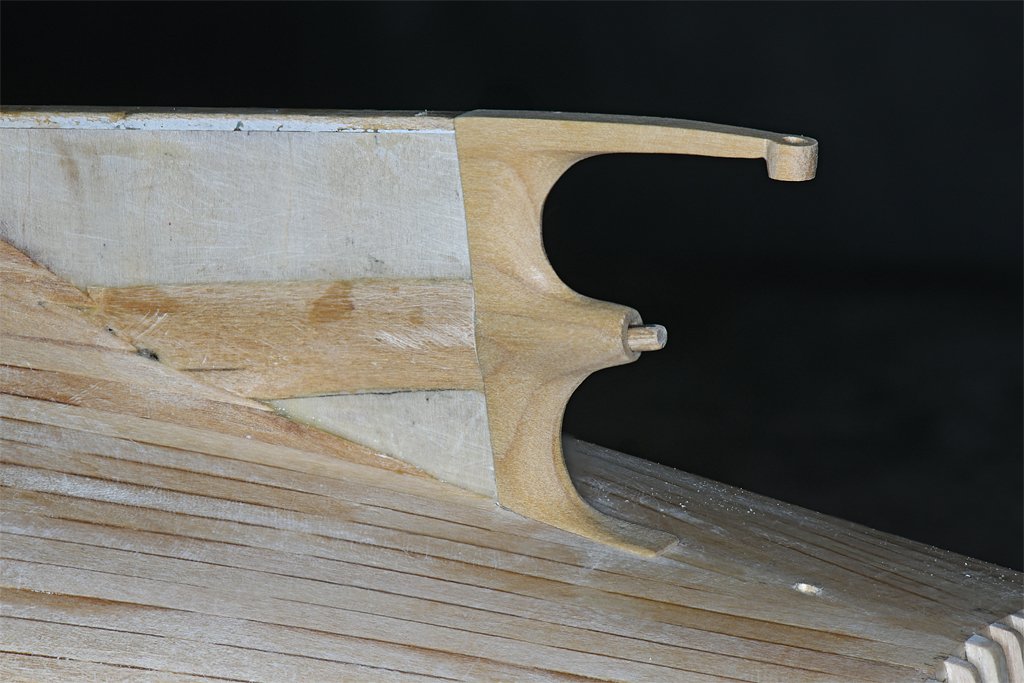
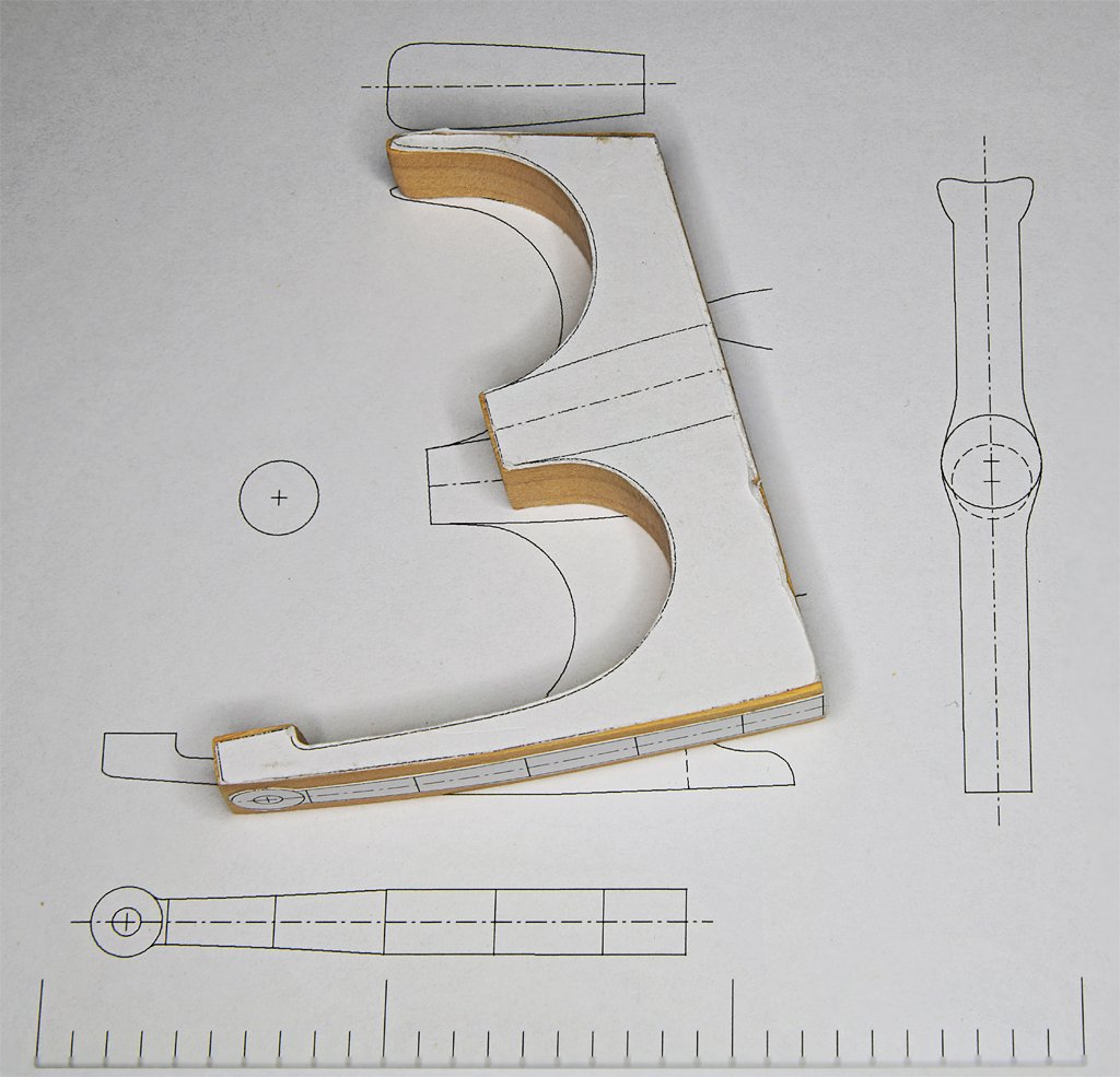
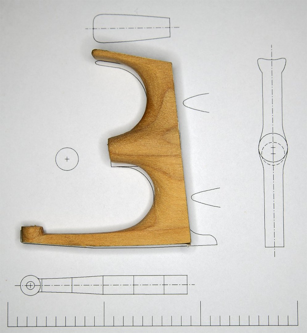
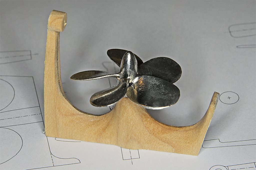
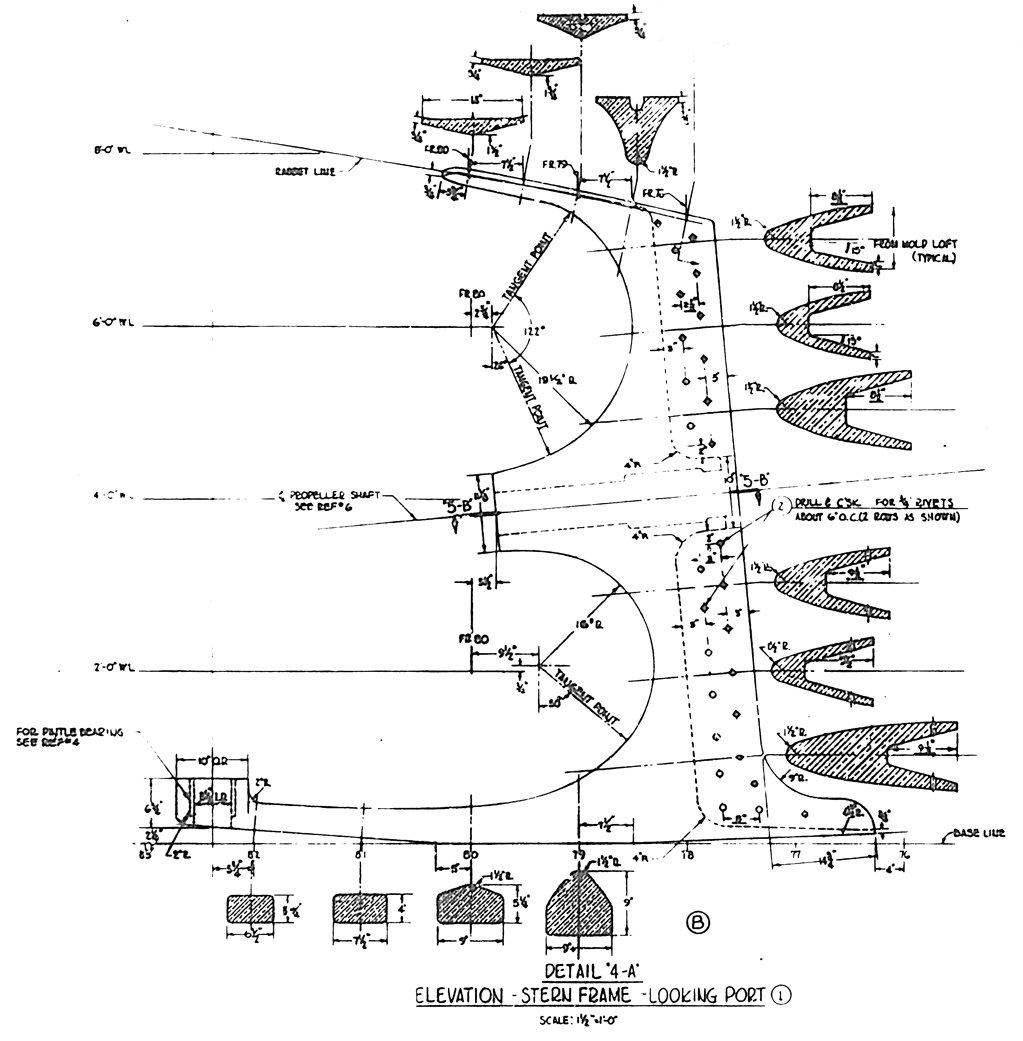
This is part of the blueprint for the stern frame. The original piece was an aluminum bronze casting. I would have liked to make it of brass, but I don't have the tools to do a good job. I have the tools and a fair amount of experience carving wood so I decided to give that a try. The nice thing about this drawing is it shows a lot of the cross sections, and that tells how to remove material from the piece. The casting had a "foot" projecting forward of the base that fit into a cutout in the keel. I have omitted this foot and cut the piece straight on the forward edge. I have never worked with Castello boxwood before so this was a learning experience. It is a relatively hard wood with fine grain. Growth rings are evident, but there was no noticeable difference in carving the darker and lighter parts. It carved easily with no chipping or splinters, and holds a fine edge. The first thing to do was clean up the rough cut piece and trim to near the lines. I also glued paper outlines of the top, bottom and ends to show where wood needed to be removed. Then I used rasps and files to cut away the unwanted wood until I had a piece of the approximate shape. I completed most of the work in an afternoon. The part shown here is still a bit oversized on all surfaces. I will wait until it is installed on the hull to file and sand the part down to be flush with surfaces on the keel/deadwood. The rudder pivots on the cylindrical part at the end of the long arm. The wide upper part will be shaped to fit flush with the hull planking. I took the advice of bdgiantman2 and got the five blade propeller from Bluejacket Shipcrafters. It is slightly oversized but fits easily in the opening formed by the stern frame. That was a LOT easier than designing a propeller in CAD and then 3D printing it! I plan to use a 1/8 inch (3.175 mm) wooden dowel as the propeller shaft. Epoxy will glue the prop to the shaft. I will use the hole in the stern frame as a template to drill a hole into the keel/deadwood of the hull. The wooden prop shaft will also serve as a pin to help hold the stern frame in place. Now I need to fit the piece to he hull.
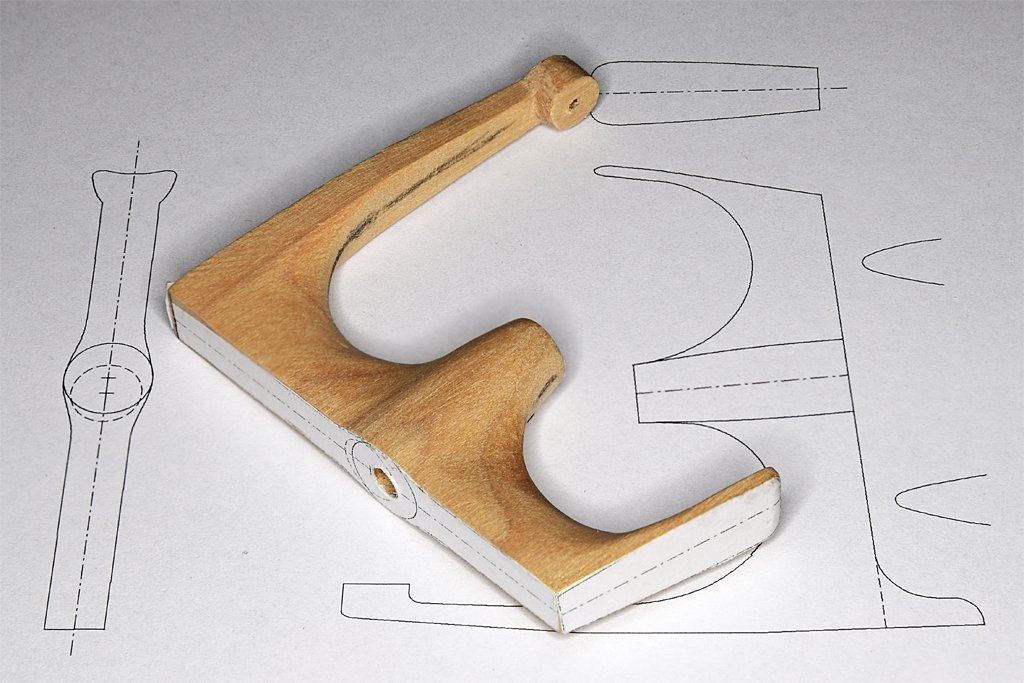
- 464 replies
-
- 13
-
-
-

-
- minesweeper
- Cape
- (and 1 more)
