
HOLIDAY DONATION DRIVE - SUPPORT MSW - DO YOUR PART TO KEEP THIS GREAT FORUM GOING! (89 donations so far out of 49,000 members - C'mon guys!)
×


Dr PR
-
Posts
2,441 -
Joined
-
Last visited
Content Type
Profiles
Forums
Gallery
Events
Everything posted by Dr PR
-
 I nibbed the deck planks on my topsail schooner build, and I am currently nibbing the planks on my minesweeper build: https://modelshipworld.com/topic/19611-albatros-by-dr-pr-finished-mantua-scale-148-revenue-cutter-kitbash-about-1815/?do=findComment&comment=605072 https://modelshipworld.com/topic/37060-uss-cape-msi-2-by-dr-pr-148-inshore-minesweeper/?do=findComment&comment=1109001 The schooner planking wasn't too bad because the planks were 5 mm wide. The minesweeper planks are 1/16 inch (1.6 mm) and it is much harder getting neat nibs! I hope someday to resume my 1:96 scale USS Oklahoma City CLG-5 model, and I was planning on planking the deck with nibs. But those planks will be about 1 mm (0.040 inch) wide and there is NO WAY I can nib those tiny planks neatly!
 -
The studding sail booms were wood, the boom irons were iron. The position of the irons and booms depended upon if the ship was continental (Europe), British, or commercial (non-warship). The irons were attached to the yard arms in several ways, again depending upon who operated the ship.
-
Some lines will not have large coils at the belaying point, especially if that they haul on is let all the way out. For example, if a foresail is reefed the halliard will be let out all the way with little left to coil. On the other hand, if the sail is hauled all the way up there will be a lot of extra halliard line to coil at the belaying point. As you say, the stays on the jib boom and flying jib boom do not have to be adjusted much, so there never will be a large coil of line at the belaying point.
-
hull finishing
Dr PR replied to serpe's topic in Painting, finishing and weathering products and techniques
serpe, What do you want to achieve with your model? -
Most of the wood we use for modelling has been dried - unless you cut strips from fresh wood. Wood shrinks significantly as is dries, and swells when it gets wet. Even just high humidity can cause wood to swell a bit. This swelling and shrinking can cause cracks to appear in seams between planks months or years after the model was built. I coat the interior of the planked hull with thin epoxy to glue everything together solidly. This prevents cracks from appearing due to changes in humidity. When you soak planks for bending, be sure they are dry before putting them on the model. If you bend planks on the model, as I do, use only a small amount of water brushed on the strip, and heat until the moisture evaporates.
-
I followed Tom Lauria's YouTube procedure in Making Sails for Ship Models From Silkspan. Here is a link: https://modelshipworld.com/topic/19611-albatros-by-dr-pr-finished-mantua-scale-148-revenue-cutter-kitbash-about-1815/?do=findComment&comment=1035392 Using your frame should give better results!
-
Dusting finished ships
Dr PR replied to bigcreekdad's topic in Painting, finishing and weathering products and techniques
I use a small paintbrush to loosen the dust. I hold the end of a vacuum cleaner hose close to the model to suck up the loosened dust. CAUTION: Remove any loose parts (not fastened down) first or you may have to sort through all the dust and lint in the vacuum bag. Guess how I know? -
Most people seem to use a plank bending method with the planks off the hull and in some type of jig. Some boil or steam the planks, and some people just soak them. In my opinion this is all way too much trouble and the results are less than perfect. For me the best way is to shape the plank on the hull, where the hull serves as the jig and has the exact curvature and twist necessary. Here are a couple of links that illustrate this method. https://modelshipworld.com/topic/37060-uss-cape-msi-2-by-dr-pr-148-inshore-minesweeper/?do=findComment&comment=1074225 https://modelshipworld.com/topic/37060-uss-cape-msi-2-by-dr-pr-148-inshore-minesweeper/?do=findComment&comment=1075263 You don't say what type of "plank bender" tool you are trying to use. That could influence the method you try.
-
When I first saw your pictures I imagined an auger screw stoker mechanism as used on some steam locomotives. But then I realized it was a conveyer bucket system. These were in common use so it makes sense. But it would be interesting to see how it actually worked. It was probably steam powered. When steam pressure was high the stoker would run slower, and when the pressure was low it would have to "shovel" faster. I hope you find more information about how it worked. I wonder if it was patented?
- 457 replies
-
- 3
-

-
- sternwheeler
- Hard Coal Navy
- (and 1 more)
-
Sagrado, Since the HMS Beagle was a British Royal Navy ship you should look for information about how the Royal Navy was rigging the lifting tackle in the first half of the 1800s. I would bet on the rig shown in your first images from "The Age of Sail." However, keep in mind that there were probably as many ways to rig these tackles are there were ships, Captains and Bosuns. If you cannot discover exactly how it was done on the Beagle (and did the method change over time?) you are free to do whatever you want so long as it is reasonable.
- 27 replies
-
- 1
-
-
- capstan
- small boats
- (and 1 more)
-
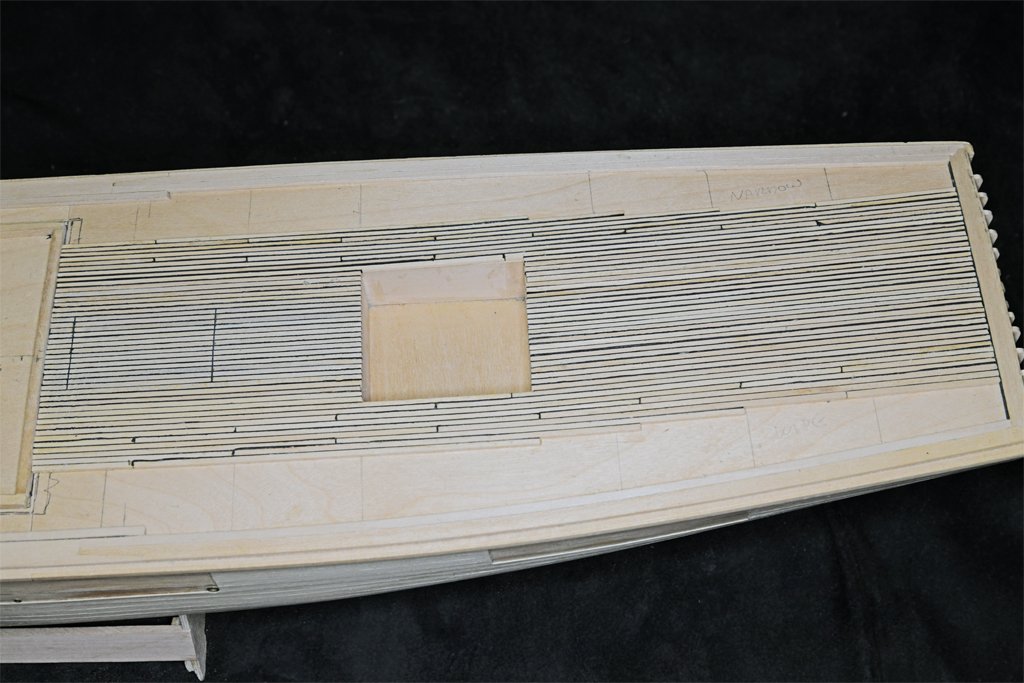
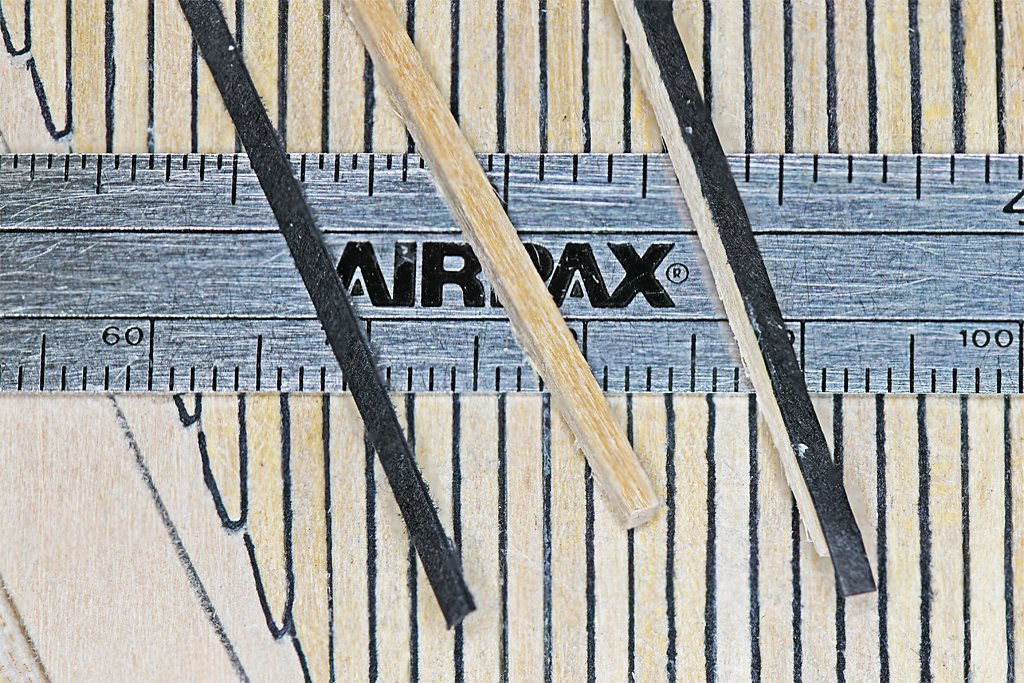
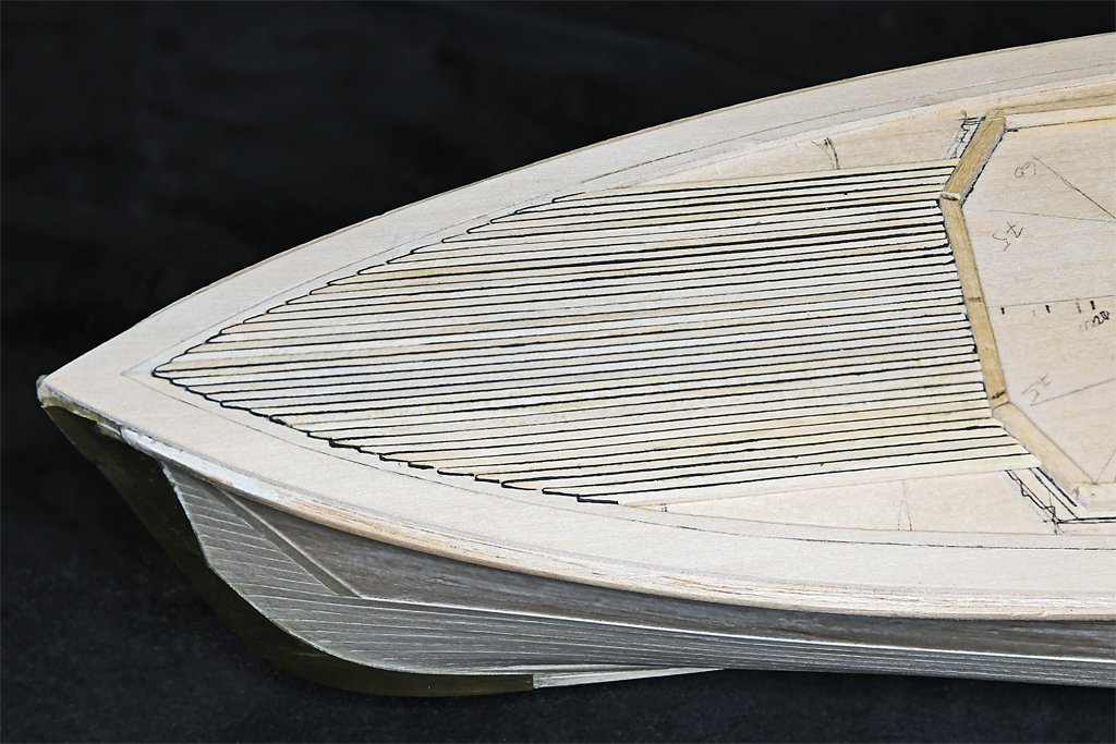
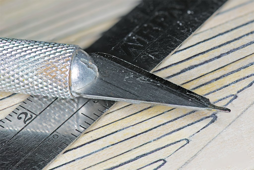
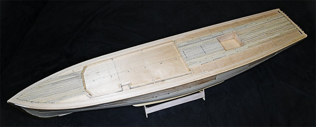
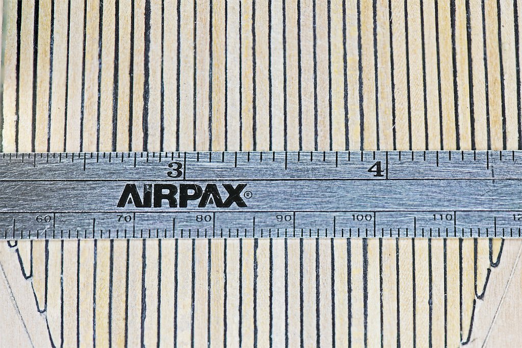
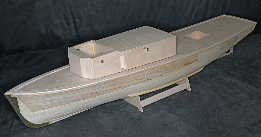
I have been planking the main deck. As you look at these photos keep in mind that this is the rough deck. It has not been sanded or sealed. The blueprints say plank ends will be spaced at least four frame spaces with three passing strakes between butts in line. The planks should be laid parallel to the centerline "... in as long lengths as practicable ..." How long was "practicable" when they were building this ship? The planking strips are 24 inches (610 mm) long. I decided to use 5 inch (127 mm) long planks (20 scale feet or 6 scale meters) because that is 16 frame spacings. This way I can use multiples of 4 frame spaces (1.25 inch or 31.75 mm), or planks 1/4, 1/2, 3/4 and 1 plank length long to stagger the plank ends lengthwise. Some of the planks are actually longer that 16 frame spaces at the bow and stern. The blueprints specify deck planks 2 5/8 inch (66.7 mm) square, or 0.055 inch (1.4 mm) at 1:48 scale. The closest commercially available strips were nominally 1/16 x 1/16 inch (0.0625 x 0.0625 inch or 1.6 x 1.6 mm). However they range from 0.055 to 0.075 inch (1.4 to 1.9 mm) and none are actually square in cross section. I cut the strips to the desired plank length and then glue a strip of black paper to one side. I usually place the narrowest dimension of the plank vertically so it will take fewer strips to plank the deck. The paper is about 0.005 inch (0.127 mm) thick, and this is 0.24 inch (6.1 mm) at 1:48 scale. The blueprints call for a 0.25 inch (6.4 mm) grout so the paper and glue are just about the perfect thickness. The paper strips were cut on an ordinary paper cutter, eyeballing the widths, so they are not uniform. They protrude a bit above the tops of the planks. With handling the tops of the paper strips "fuzz out" and appear wider than the nominal width, making the grout look non-uniform. But after all the planking is done the deck will be scraped, sanded and finished with #0000 steel wool and the grout lines will be much more uniform in width. Nibbing the planks into the nibbing strake along the edge of the deck is much harder that it was on the topsail schooner build - it had 5 mm wide planks. As you can see in this macro photo the nibbing isn't "perfect." It has taken a bit of practice to get it more uniform in appearance, and I screwed up in a few places. Fortunately part of the fore deck is covered by a steel chafing plate where the anchor chain runs, and this will cover the worst of the screw-ups! Phil 1, Murphy 0! I soon learned that I could not cut uniform nibs with just a #11 hobby knife blade. The solution was to use an old, dull #11 blade with a broken tip, and shape the tip to make a "nibbing tool." I used a grinding wheel in my motor tool and cut the tip to about 0.030 inch (0.76 mm) wide, with a chisel tip on the end. This is about half a plank width, and that is how wide the nib tip should be. I ground a cutting edge on the end, and then sharpened it on a whet stone. I first use this tool to make the initial cut at the edge of the nibbing strake. Then I cut back from there to where the plank edge meets the edge of the nibbing strip. The plank is then shaped to fit the nib cutout. I usually have to trim the plank a bit narrower at the nib to account for the thickness of the paper grout. No two nibs have the same angle cut, and the nibs get longer as the planking progresses toward midships. Some of the planks will have very long tapers, especially along the deck house sides. It is pretty tricky trying to cut long straight tapers into the nibbing strake.
- 464 replies
-
- 13
-

-
-
- minesweeper
- Cape
- (and 1 more)
-
Valeriy, I am aware that the calculations for creating truncated cones are on line - I even have them in an ancient printed analytic geometry text book. But the Internet takes the fun of doing the trigonometry out of it, doesn't it? But where your experience comes into the story is that you know how to do it, and know what to look for to do the calculations. And of course you do excellent work with brass and soldering! That is part of your talent.
-
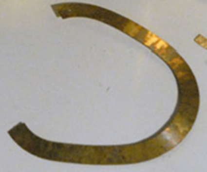
Valeriy is too modest - he is obviously one of the most talented ship modelers on the planet! All of the great tools will not build a model, not even in the hands of an untalented modeler. The geometry of the "ventilator visors" is not trivial. It looks like he made them from four pieces - two curved ends and two straight sides. Those curved ends are halves of a conic section, and anyone who has tried to figure out the correct "flat" layout for a conic section knows it isn't trivial. Try cutting a truncated cone with specific angles from a piece of paper and you will see it isn't easy! I designed this single piece "visor" in 3D CAD and that takes a lot of patience. In this case the smoke pipe had different radii fore and aft. I had to flatten the 3D model into a 2D plane, one facet at a time (the program didn't have a "flatten" function). That was very tedious! Then I photo etched the part (sorry for the blurry picture). It was a lengthy and non-trivial process that took several days. Valeriy is very good at this sort of thing and makes it look all too easy!
-
It was common on many vessels (especially smaller non-military ships with small crews) to forego the becket and just tie the standing part around the block strop. In some cases the standing part of the tackle was tied in a knot around the block strop, as illustrated in Monfeld's Historic Ship Models on page 245. Some people just loop the standing end under the block strop then pull the end back and seize an eye around the strop. This is perhaps the best way to attach the standing end on small scale models. Sometimes a separate length of line was pulled under the strop, looped around a thimble and seized to create a becket. And on some ships a separate becket was seized into the block strop. I suspect this method was more common on naval ships with large crews with little to do when not engaged in battles. Unless you know the exact way blocks were stropped on the original vessel you are modelling you are free to use whatever method appeals to you.
- 133 replies
-
- 3
-
-
- Ranger
- vanguard models
- (and 1 more)
-
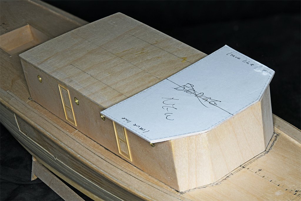
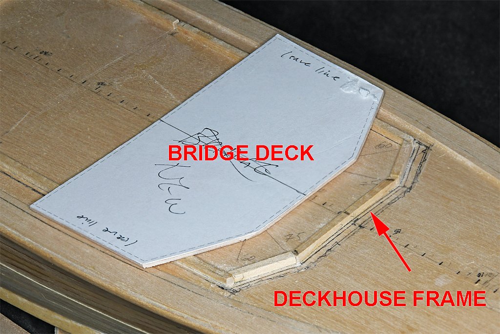
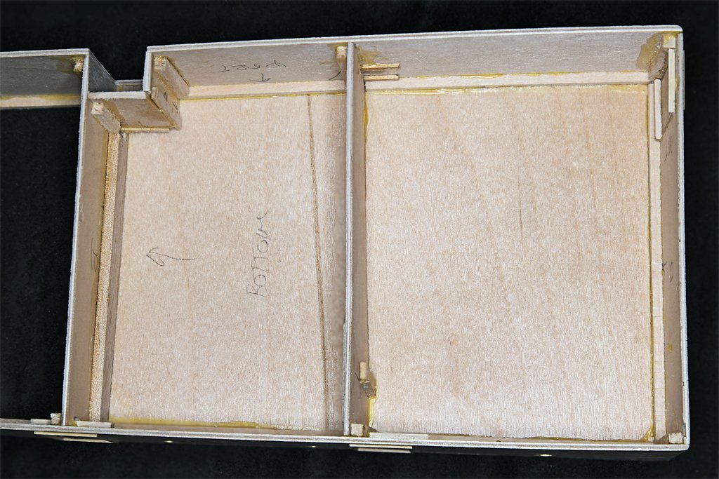
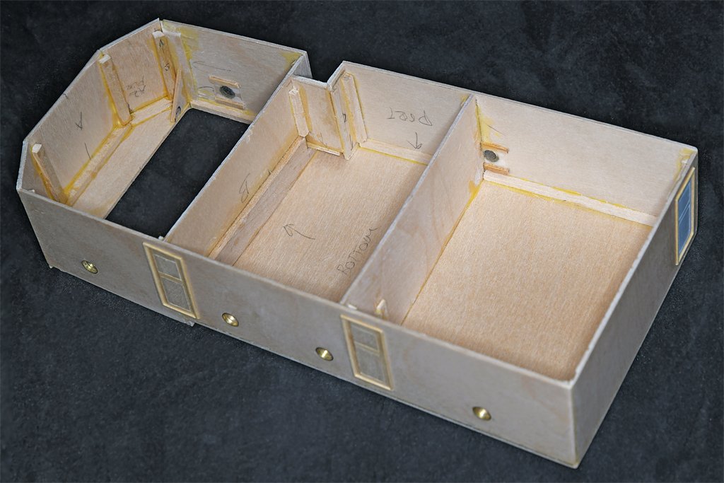
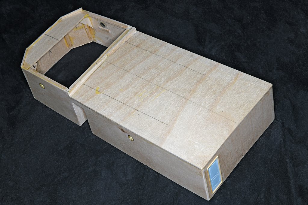
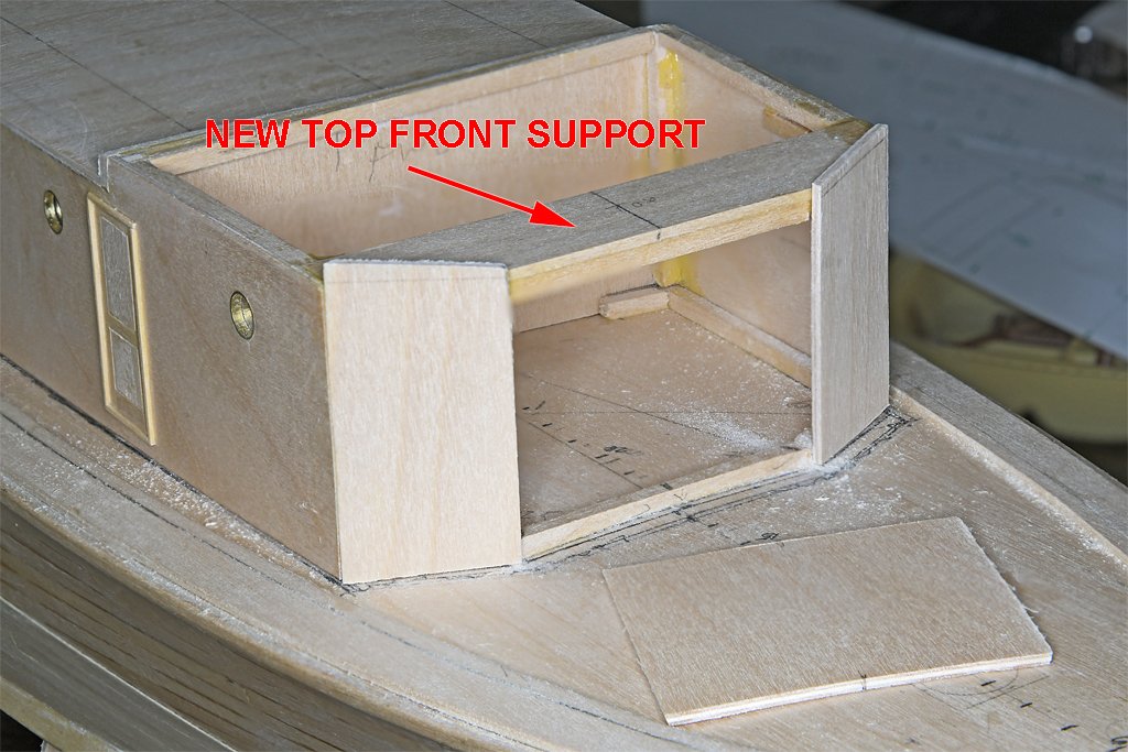
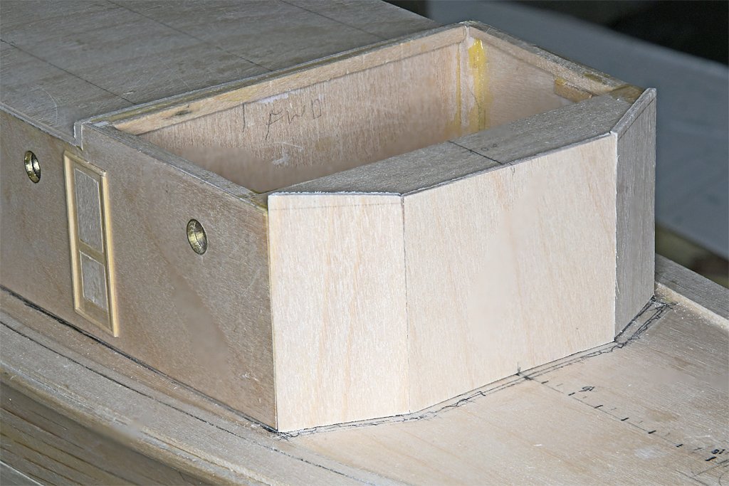
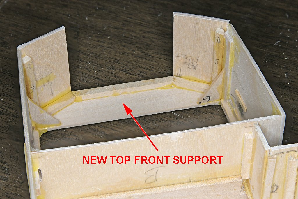
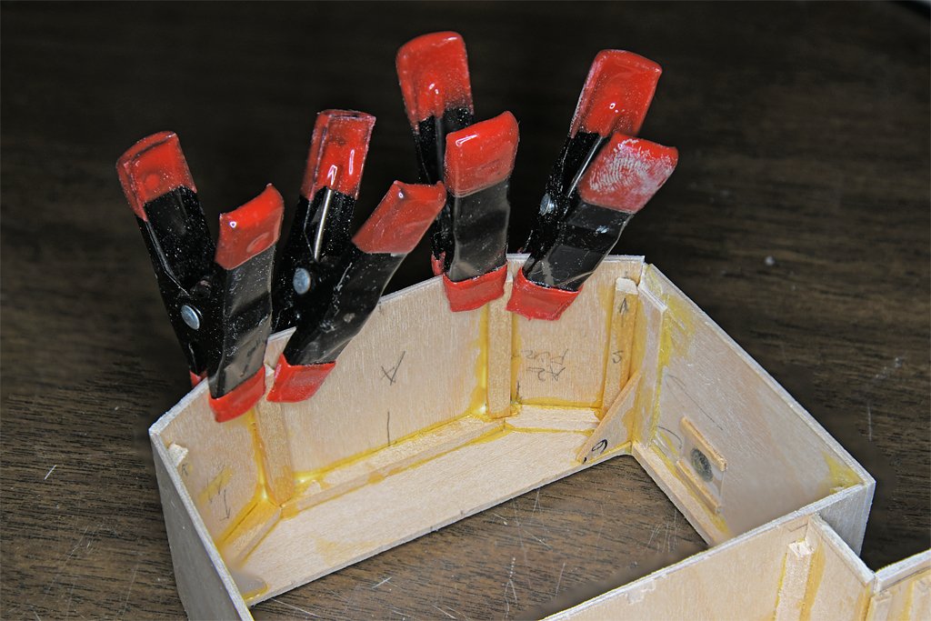
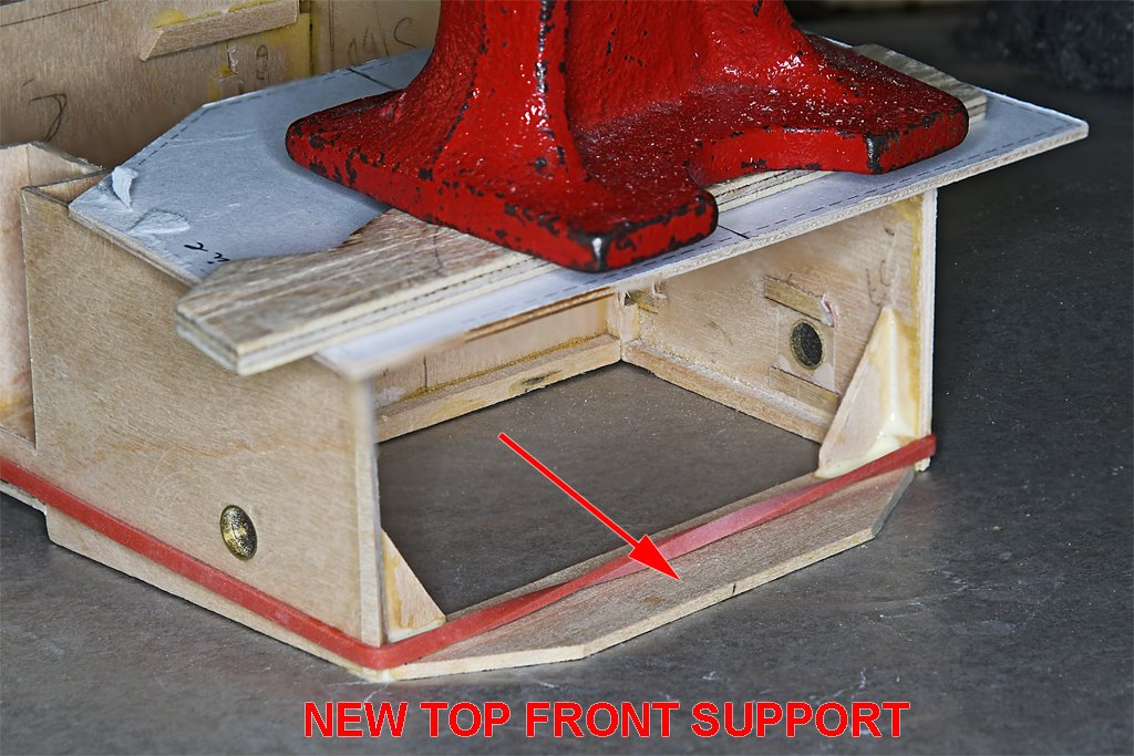
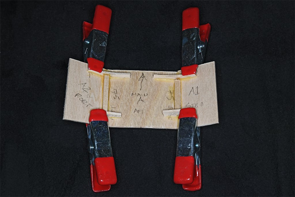
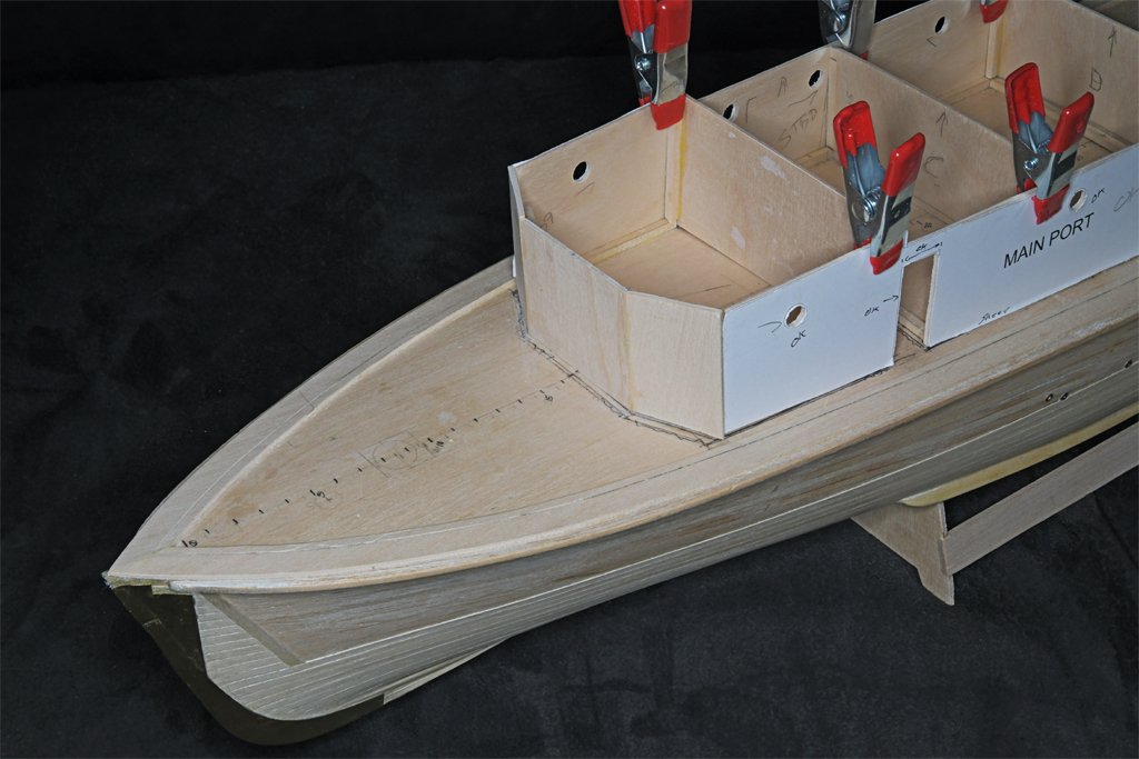
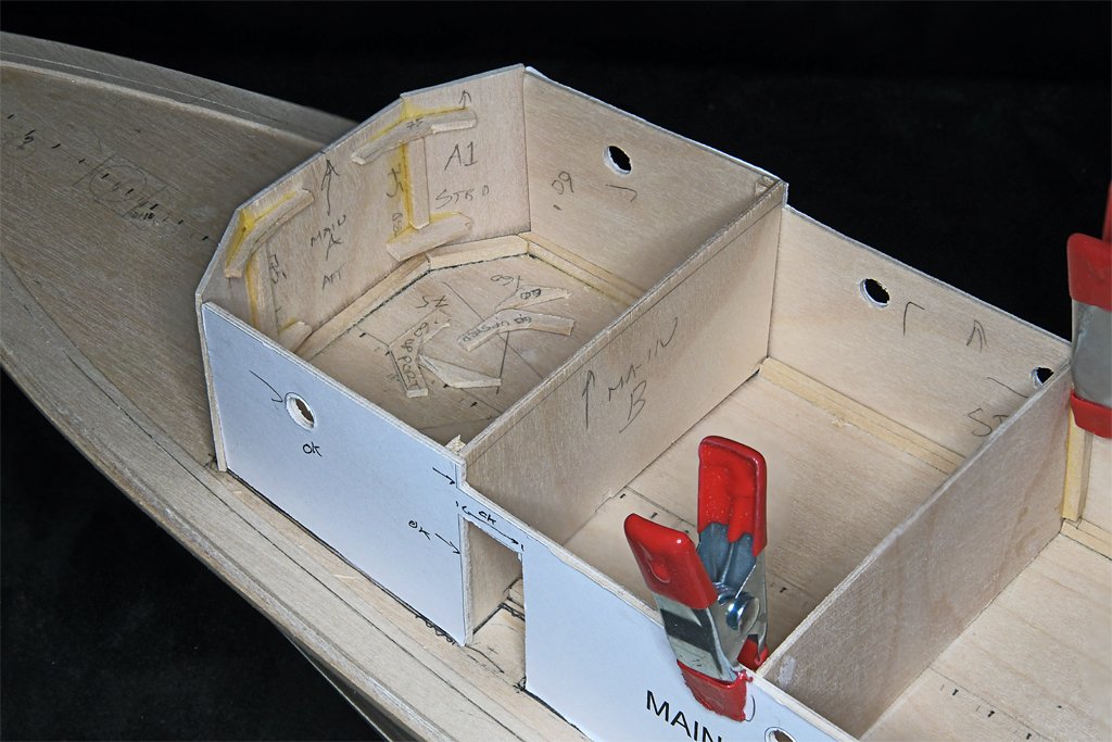
Gary, Not as nice as it might have been! A lot of things were screwed up pretty badly when the glue set. The angles of the front three panels were way off. I tried to repair the problems, but the "repaired" piece still had a lot of problems. If at first you don't succeed, try, try again. The problem seems to have been caused by the side pieces moving back and forth while I was assembling all of the panels and supports for the front of the superstructure. The thing just wasn't rigid enough to hold its shape. The blueprints show the front panels resting at an 85 degree angle to the deck, and they join each other at 150 degree angles. At the sides they join the deck house sides at approximately a 120 degree angle, but not quite because the house sides are not parallel. I double checked the deckhouse frame that is glued to the sub deck against a printed template, and all of the angles were correct. Likewise the bridge deck - that rests on the deckhouse sides - also had the correct angles. But the front panels did not align properly at the top edges with the bridge deck - they were way off in places! There wasn't any way to correct the errors, so the three front panels were chopped out and I started over. The first thing to do was realign the sides and rear bulkhead to the deckhouse frame and glue it all together. Then the top rear O1 level deck was glued on. Once this was in place the structure was rigid. This piece is 1/16 inch (1.6 mm) plywood and was pretty stiff. The deck has camber, but no sheer. The interior bulkheads were all cut with the camber, so I needed to bend the plywood to the correct curvature. I wet the plywood and then bent it over a couple of wooden sticks. The edges were clamped to a very stiff 1/4 inch (6.35 mm) thick piece of aluminum plate. Then the plywood was pre-heated with a hair dryer and the whole thing was placed out into the noon day sun. After a few hours at 80+ Fahrenheit (28 Celsius) the plywood was dry and had adopted a nice camber. While the glue was setting I added the walls for the small nook in the port side of the deckhouse. There is a scuttle in the main deck here that was the escape route for the forward minesweeping generator engine room. With the rigid deckhouse structure to work with I devised a simple solution for aligning the front panels. I cut a piece of 1/16 inch (1.6 mm) basswood to match the shape of the front of the deckhouse frame and bridge deck. After the leading edges of the sides were prepared at the proper angles to mate with the front pieces, the new top front support was glued into place, with a couple of additional supports to strengthen the assembly. In this photo the deckhouse is upside down and resting on a sheet of waxed paper. I applied an excess of Titebond Original glue to be sure everything was glued together. The waxed paper prevented the deck house from being glued to the work bench. I have had enough problems with this already and don't need for that to happen! Next I shaped the two side panels to fit the house sides, deckhouse frame and top front support piece. These pieces were cut oversized on all sides and then cut, filed and sanded to fit. Then they were glued into place, and additional support pieces were glued into the angles between the front pieces and the house sides. I wanted these parts to be well supported. Note that the deckhouse parts are not glued to the deckhouse frame on the main deck. I want to remove the deckhouse while planking the deck, and to continue construction of the O1 level deckhouse and bridge away from the hull. After the side panel glue had hardened over night I shaped the front panel piece to a tight slip fit between the side panels. Then it was glued into place. They say the proof of the pudding is in the tasting - or in this case how well the bridge deck fits to the deckhouse structure. It is as close to a perfect fit as I can get! All of the angles align the way Phil and BuShips intended. I should have assembled it this way in the first place (hindsight is always clearest)! Now I can start the main deck planking, and while the glue is setting I can do some work on the O1 superstructure (radio room and pilot house) and bridge. Here are a couple more photos of the main deck deckhouse. And the deckhouse in place on the hull.
- 464 replies
-
- 11
-
-
-
- minesweeper
- Cape
- (and 1 more)
-
Shellac will hold the seizing, but it doesn't adhere to polyester rope. It hardens and appears t hold the rope - as do other glues. But if you put a strain on the rope the polyester will just slip through the glue like it was greased!
- 133 replies
-
- 3
-
-
- Ranger
- vanguard models
- (and 1 more)
-
I would add a word of warning about stropping blocks (and other things) with seizing. I used polyester rope with very fine silk thread for seizing. After wrapping the seizing tight I soaked it with white glue. After the glue dried the seizing was very solid. But the glue did not stick to the polyester rope, and it easily pulled out of the seizing if any strain was placed on the assembly. This left a nice tight hollow tube of seizing around one end of the rope, and a failed rigging. This happened to seizing that had been made weeks earlier when I started adding the rigging to the model. This caused a lot of difficult repairs! I tried several different glues to fasten the ends of the polyester rope together. All failed except CA (cyanoacrylate or super glue). After wrapping the rope around the block (hook, eye, etc.) I place a small amount of CA on the two strands of rope. Then I wrap the seizing around it. If I try to tie the seizing over the wet CA I cannot wrap the seizing fast enough before the glue hardens. The result is a lumpy seizing. I spread the CA evenly and let it harden before starting the seizing.
- 133 replies
-
- 3
-
-
- Ranger
- vanguard models
- (and 1 more)
-
I recommend you glue the hatch gratings in place after all the work around them is complete. I left the hatch gratings loose on a model I built back in the 1960s, with just gravity and a tight fit holding them in place. Decades later, having forgotten the gratings were loose, I was dusting the model with a soft brush and a vacuum cleaner off to the side when suddenly the hatch grating popped up and went into the vacuum cleaner. Digging through the dust, hairs and miscellaneous bits of this and that is not something you really want to do! The gratings have since been glued in place.
-
Very nice! The model is starting to look like the real thing.
-
Pear wood stained with Varathane "Gunstock" color wood stain produces a nice reddish "mahogany" color. https://modelshipworld.com/topic/37060-uss-cape-msi-2-by-dr-pr-148-inshore-minesweeper/?do=findComment&comment=1107586
-
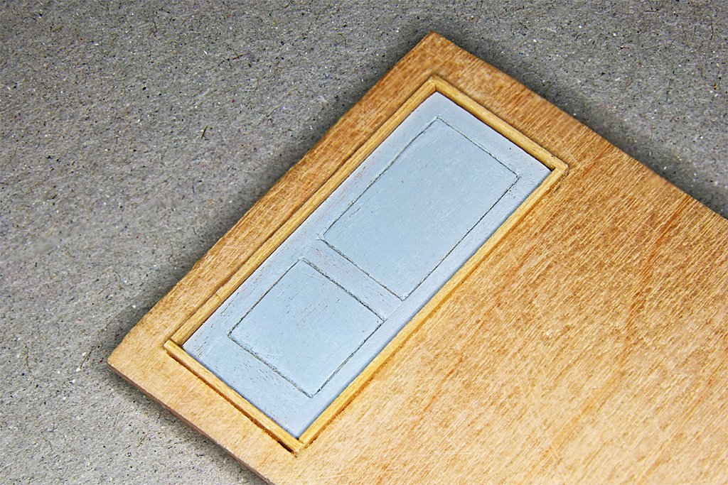
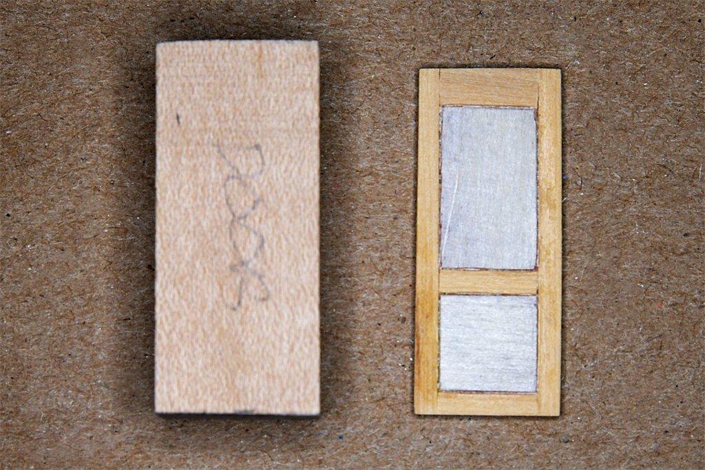
A bit more progress on the doors and deckhouse. These are the pilot house doors. The door on the left is partially assembled. It is 1/32 (0.0325) inch (0.8 mm) thick pear wood strips and panels glued onto a 1/32 inch thick plywood backing. This is the rough door before sanding and staining. I knew I couldn't create uniform width grooves for the white trim, so I took a hint from small craft builders who needed white grout between planks. I used some 0.020 inch (0.5 mm) white styrene strips. The window is a 0.005 inch (0.13 mm) thick piece of acrylic sandwiched between two thin (>0.015 inch/0.38 mm) rings cut from a 0.28 inch (7.1 mm) diameter brass tube. The inside diameter is 0.25 inch (6.4 mm) or 12 inches at 1:48 scale. The door on the right is finished with Varathane wood stain, in the "Gunstock" color. The pear stains nicely and I like the resulting reddish "varnished mahogany" color. I have been wondering how to get a good mahogany color and this stain works well. All of the door and window trim around the pilot house was mahogany. While rummaging through my wood stash I found a bag of 3.75 x 0.093 x 0.045 inch (95 x 2.4 x 1.1 mm) HO scale railroad ties that appear to be real mahogany! I remember buying these in the 1970s to be used as hull planks for a scratch built ship's boat. These "ties" are a good size for the door and window trim, and the window frames. I was working on the doors while the glue set on the deck house assembly. This assembly is tricky because there are no right angles. The deck house is narrower at the front than at the rear, so the sides aren't parallel. The deck has significant sheer forward but the bulkheads should be vertical perpendicular to the water line. The attachment of the forward angled bulkheads to the side pieces is critical for getting all the other pieces right. I added a lot of interior bracing to make it strong enough to hold up to handling The first attempt to put it together came out too wide, and it didn't fit the house outline framing glued to the subdeck. I had to disassemble the port side and reshape the pieces to fit correctly. I am using Titebond Original wood glue and it can be softened with water and heat. So I soaked the joints and heated them with a hair dryer. It came apart "reluctantly!" The interior bulkheads are just clamped in place at this point. They set the angles where the front and side pieces join.


- 464 replies
-
- 10
-
-
-
- minesweeper
- Cape
- (and 1 more)
-
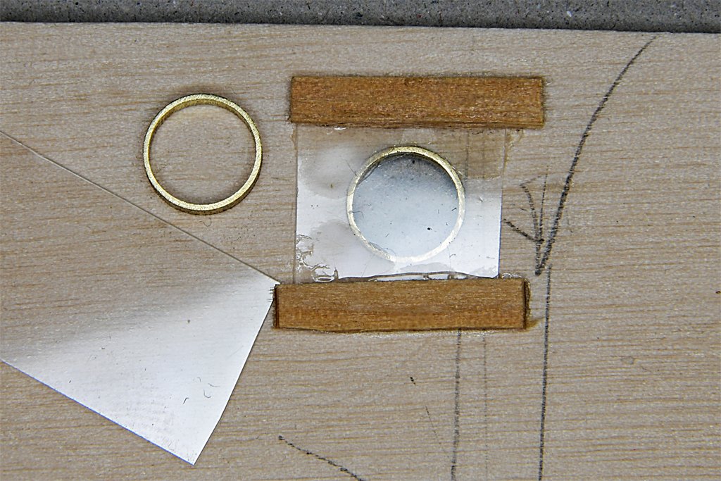
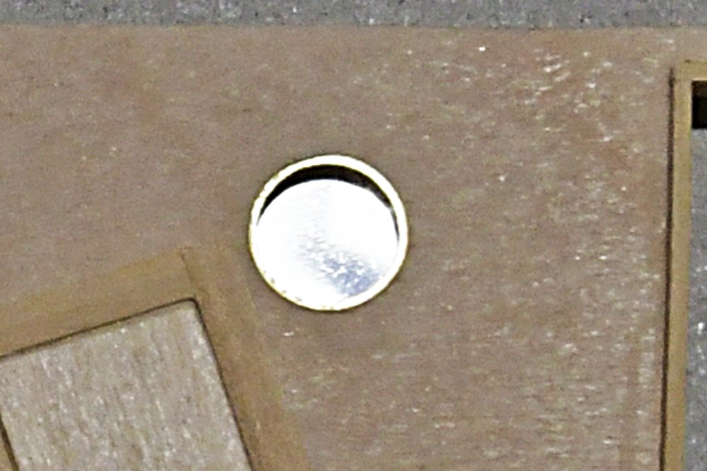
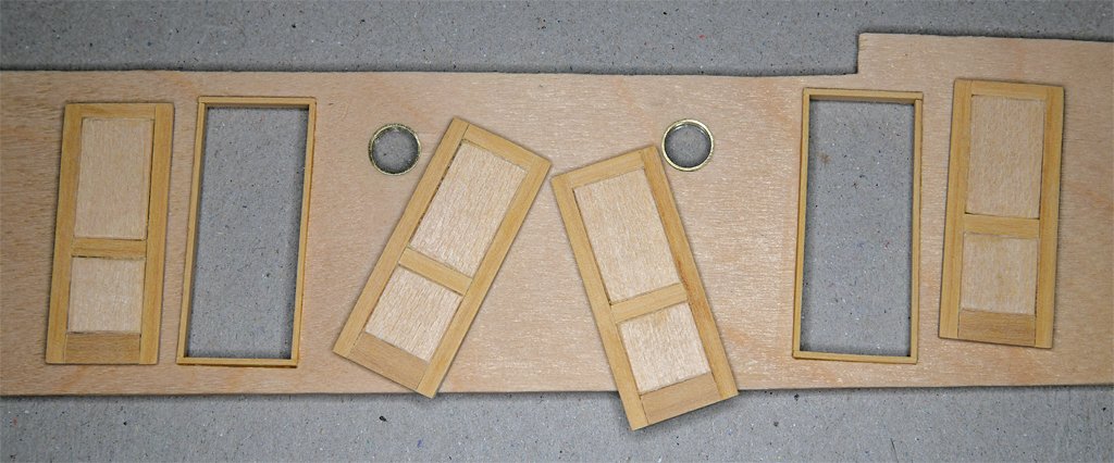
Here is a bit more progress on things that must be done before the deck house parts are assembled. I have cut out the door and air port openings on the deck house sides. Then I stripped off the paper templates, sanded the wood smooth and applied a coating of acrylic sealer. And I made all the weathertight doors except the mahogany doors for the pilot house. This is the prototype door positioned in the after deckhouse bulkhead - with the panels removed and installed correctly! I am using Titebond Original wood glue, and it can be loosened with heat. I used my plank bending/sail making/quilting iron tool as a debonding heater to loosen the glue. The door frames are 1/32 x 3/32 inch (0.8 x 2.4 mm) boxwood strips glued into the opening in the 1/16 inch (1.6 mm) thick plywood bulkhead. Technically the bottom sill should be 0.0026 inches (0.066 mm) thicker than the side and top sills, but with my tools I have no way to produce this. The grooves in the door stand out nicely! The finished door will have a brass door knob made from a small brass nail. I made the air ports with a 1/16 inch (1.6 mm) long piece of 0.28 inch (7.1 mm) outside diameter brass tubing. The inside diameter is 0.25 inch (6.4 mm), or 12 inches (305 mm) at 1:48 scale. These were sawn off the end of the tube a bit longer than needed. Then they were pushed into a hole in a piece of 1/16 inch thick plywood and filed down until they were as long as the thickness of the plywood. It would have been easier and quicker with a lathe! \ I glued squares of 0.005 inch (0.127 mm) thick clear styrene on the inside of the bulkhead, with additional scrap wood pieces to hold them in place. I have considered adding an additional 3D printed piece on the inside of the air port that is shaped like the metal inside cover and painted the typical US Navy interior puke green. Whether I actually do that remains to be seen. But if I do they really won't be seen at this scale, so why bother?
- 464 replies
-
- 9
-
-
- minesweeper
- Cape
- (and 1 more)
-
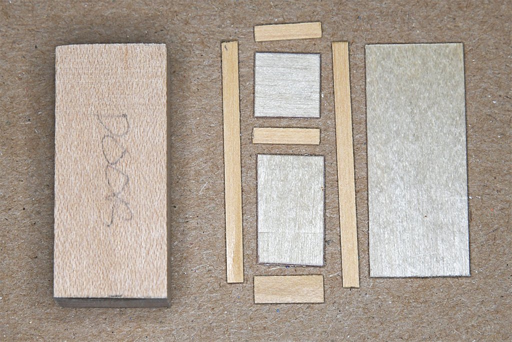
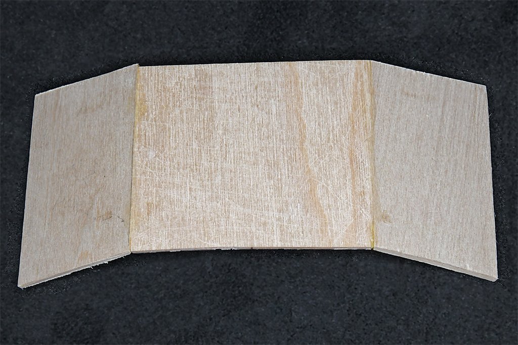
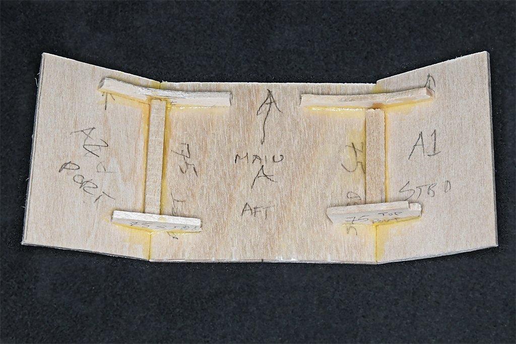
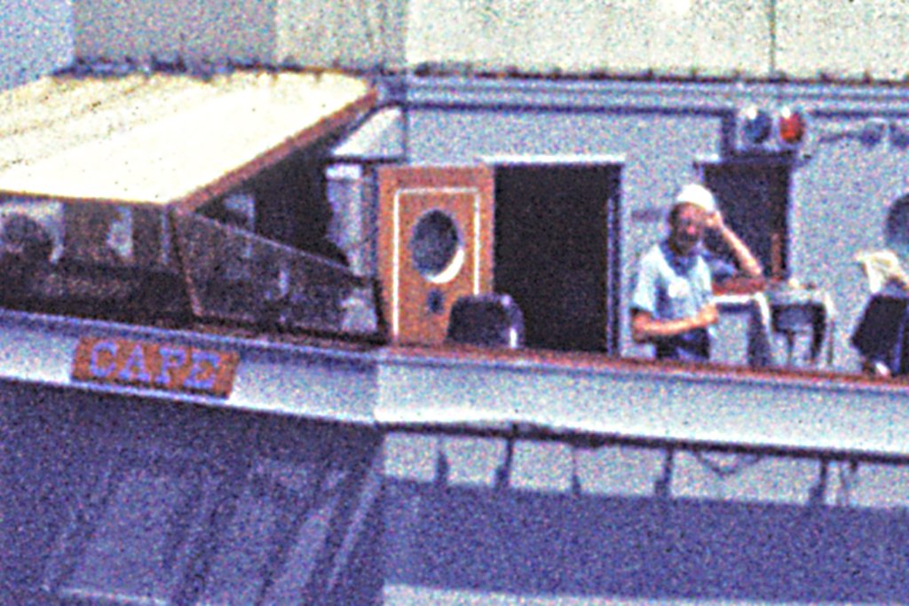
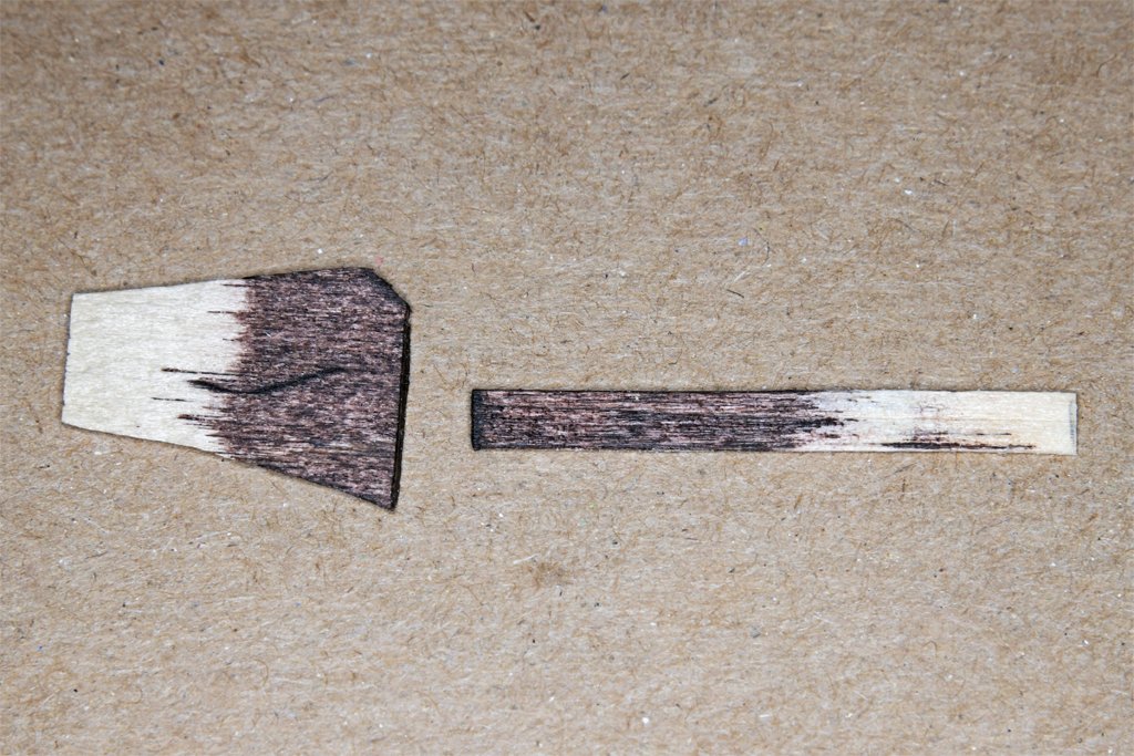
Thanks to everyone for the comments and likes! I have a bit more progress to report. The forward bulkhead of the deck house is the key to the entire assembly. The three pieces join at 150 degree angles so they must be beveled 75 degrees on the sides where they join. In addition, they have to conform to the camber of the deck, they are vertical relative to the water line, and the deck has a significant sheer. There are no "square" corners or 90 degree angles, so there is plenty of opportunity to screw up! I worried about this a lot, trying to figure out the shape of the two side pieces. I modeled it in 2D CAD, based on the deck camber. But the first two side pieces didn't come close to fitting! Then I did it in 3D CAD, taking into account the angles of the parts, and came up with what you see here. These pieces have to be assembled first. Then the rest of the deckhouse will be added to them - again at some odd angles. The house sides join the outer two front pieces at 120 degree angles, so the parts must be beveled 60 degrees on the joining edges. I used interior support pieces angled at 150 degrees to glue the pieces together. Then additional 1/8 x 1/8 inch (3.2 x 3.2 mm) pieces were glued to the inside of the joints for additional strength. I guess I did get it right because the pieces seem to come together correctly. At this point the outer front pieces are oversized and will have to be trimmed back and beveled appropriately. Only the front three pieces are glued together. Everything else is just clamped in place. There is a lot more work to do on the house sides before they can be glued to the front and interior bulkheads. There are seven "weathertight" doors (not watertight) on the exterior of the superstructure, Three at the main deck level and four on the O1 level. The doors were made like the doors in houses in the 1950s. They had two center panels that had "V" shaped grooves all around. I want to try to replicate this. Here is a "door kit." The side and top parts are 3/32 x 1/32 inch (2.4 x 0.8 mm) boxwood, the bottom piece is 5/32 x 1/32 (4 x 0.8 mm) boxwood, and the center panels are 1/32 inch plywood. The 1/32 inch plywood panel at the right is the finished door size. The other parts are glued to it to create a 1/16 inch (1.6 mm) thick door, as shown on the right. The block at the left is the template for cutting the door openings. The doors are a bit smaller, and will have 1/32 inch frames all around. There is a problem here. In my rush to assemble the door I put the wider 5/32 inch bottom part at the top! Well, it is a prototype, and Murphy had a hand assembling it. Reminds me of the topsail schooner build where I go in a hurry and switched the pintles and gudgeons for the rudder! How embarrassing! The doors were all painted gray on the outside. But inside they were varnished mahogany. The two doors to the pilot house will be open, as shown in this rather grainy photo. The grooves around the center panels were painted white. I want to replicate this in the model. The windows and window frames were also mahogany, as were the frames for the windshield, railings around the bridge and on the bulwarks, and a lot of the interior of the pilot house. I will be experimenting with pear wood to try to get the nice red mahogany color. But if that fails I will just paint the doors with "mahogany" paint. Here are pieces of the boxwood and plywood used in the prototype that have been stained with Minwax premium oil penetrating stain. This is "Red Mahogany 225." Looks more like brown mud! I have tried to use this stuff before and this is the best results I have had. Blotchy and streaked. Awful! This is why I said I may just paint the wood.
- 464 replies
-
- 11
-
-
-
- minesweeper
- Cape
- (and 1 more)
-
Keith, Search the US Patents for coal auto feeders or something like that. If there was a patent (and there probably are many) it will have drawings and an explanation how it works. Never underestimate what you may find in the patents!
- 457 replies
-
- 6
-

-
-
- sternwheeler
- Hard Coal Navy
- (and 1 more)
-
Thanks for the suggestions and offers. I'll try using the cherry and boxwood I have. If that doesn't work I may take you up on your offers.
