HOLIDAY DONATION DRIVE - SUPPORT MSW - DO YOUR PART TO KEEP THIS GREAT FORUM GOING! (83 donations so far out of 49,000 members - C'mon guys!)
×


Dr PR
-
Posts
2,438 -
Joined
-
Last visited
Content Type
Profiles
Forums
Gallery
Events
Everything posted by Dr PR
-
 There is a lot of hype and quite a bit of BS about the small "coolers" or "air conditioners." These things are useless unless there is a way to remove the heat from inside the room (blow warm air outside). Without that they are no more useful than an ordinary fan - but way more expensive. The Admiral's father wanted a "portable" air conditioner for his bedroom. It sat on the floor and had a flexible duct running to a window. Baffles in the window sealed around the duct so it could vent to the outside. It was only marginally useful for cooling the room, and could not prevent the temperature inside from rising as it got hotter outside. There are two significant problems with this arrangement. First, the warm exhaust air heats the flexible duct, and it in turn serves as a heater to return the heat to the room. The longer the duct the more it heated the room. The second problem is if the house is sealed and has few air leaks. For every bit of air blown out of the house more air has to come in somewhere (otherwise interior pressure would drop and a window might implode). This really reduces the cooling effectiveness because warm air is being sucked in somewhere else. Window mounted air conditioners do not have these problems. They recirculate interior air, so there is no problem with trying to force air out of the house. And they have heat exchangers on the outside that lose heat to the outside air. There is a new type of heat pump air conditioner and heater coming on the market. It is being developed for high rise apartment buildings that typically have low efficiency heating and cooling systems (if anything at all). It fits in a window like a window air conditioner. But unlike most of these units the new device is built like an inverted "U" with a narrow part that fits over the window sill and the parts on the inside and outside hanging down. These operate off ordinary 15 amp 125 VAC wall sockets and are very efficient. One estimate said that if all the apartments in New York City had these installed and older heating/cooling equipment was turned off, one entire large electricity generating power plant could be shut down! I have a friend who installs solar systems and other energy saving equipment and he has one of these prototype units in his house as part of a nation wide test program. The one small unit can heat and cool his house (he also has an air circulating system to move the heat around)!
 -
This is developing into a very pretty model! I like the green bulwarks. Chapelle (The Baltimore Clipper) does say green was one of the colors used on these vessels in the late 1700s and early 1800s.
- 52 replies
-
- 1
-

-
- Grecian
- Vanguard Models
- (and 1 more)
-
Ammonia! Hope you had good ventilation for that!! I have unpleasant memories of working with reagent grade concentrated ammonia. It stinks a lot worse that cyanoacrylate glue (CA)! Dows it really work better than warm water?
-
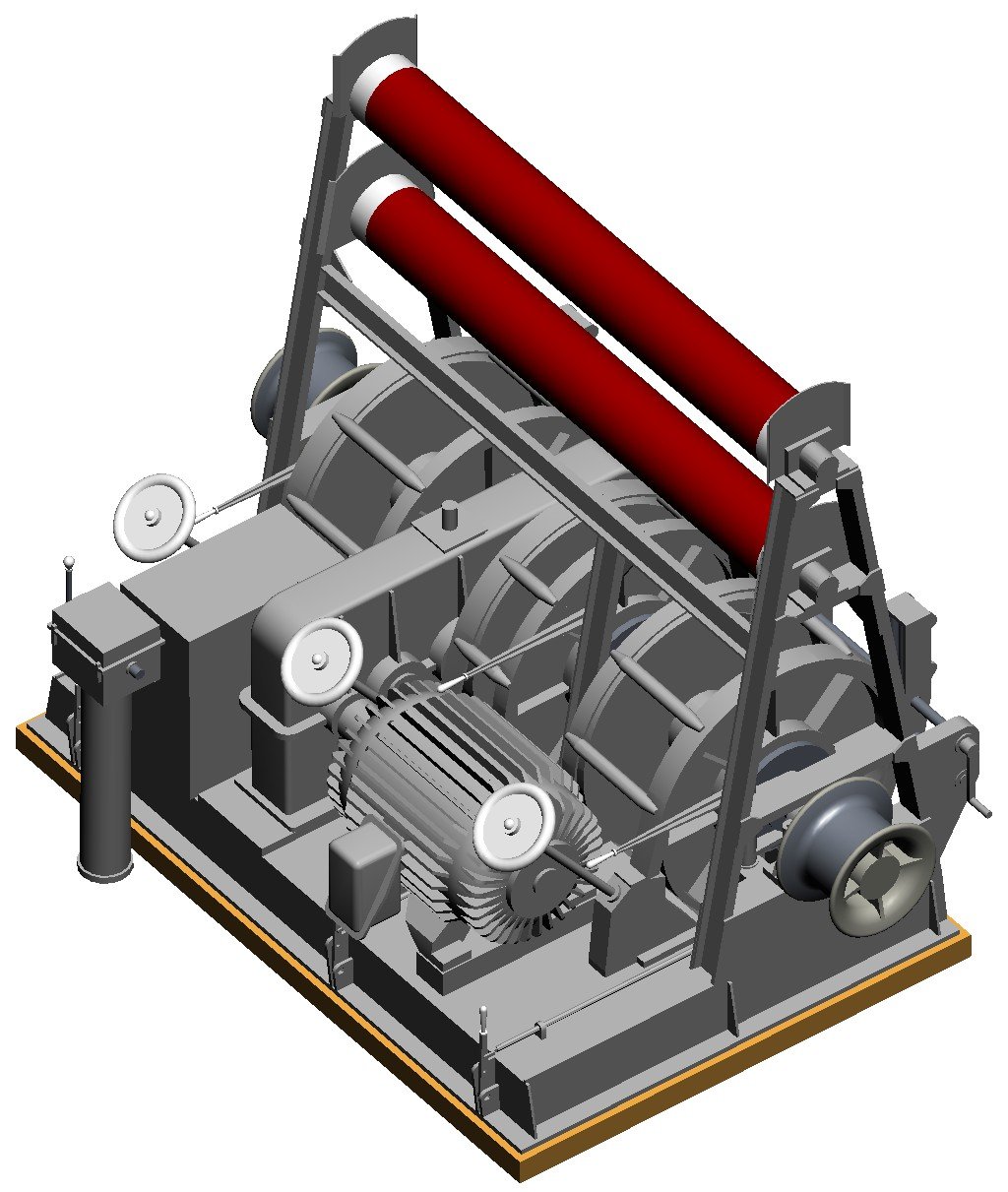
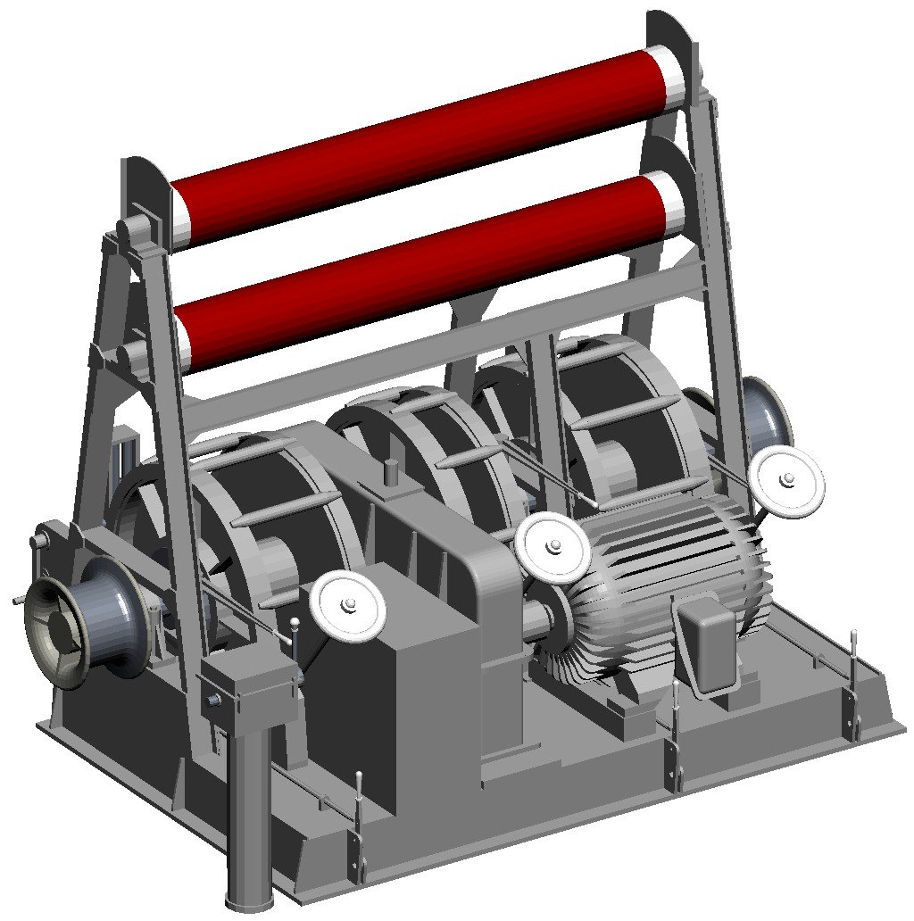
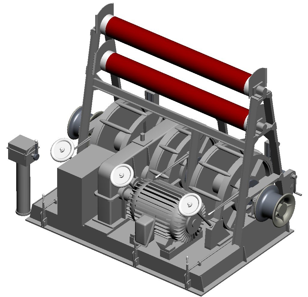
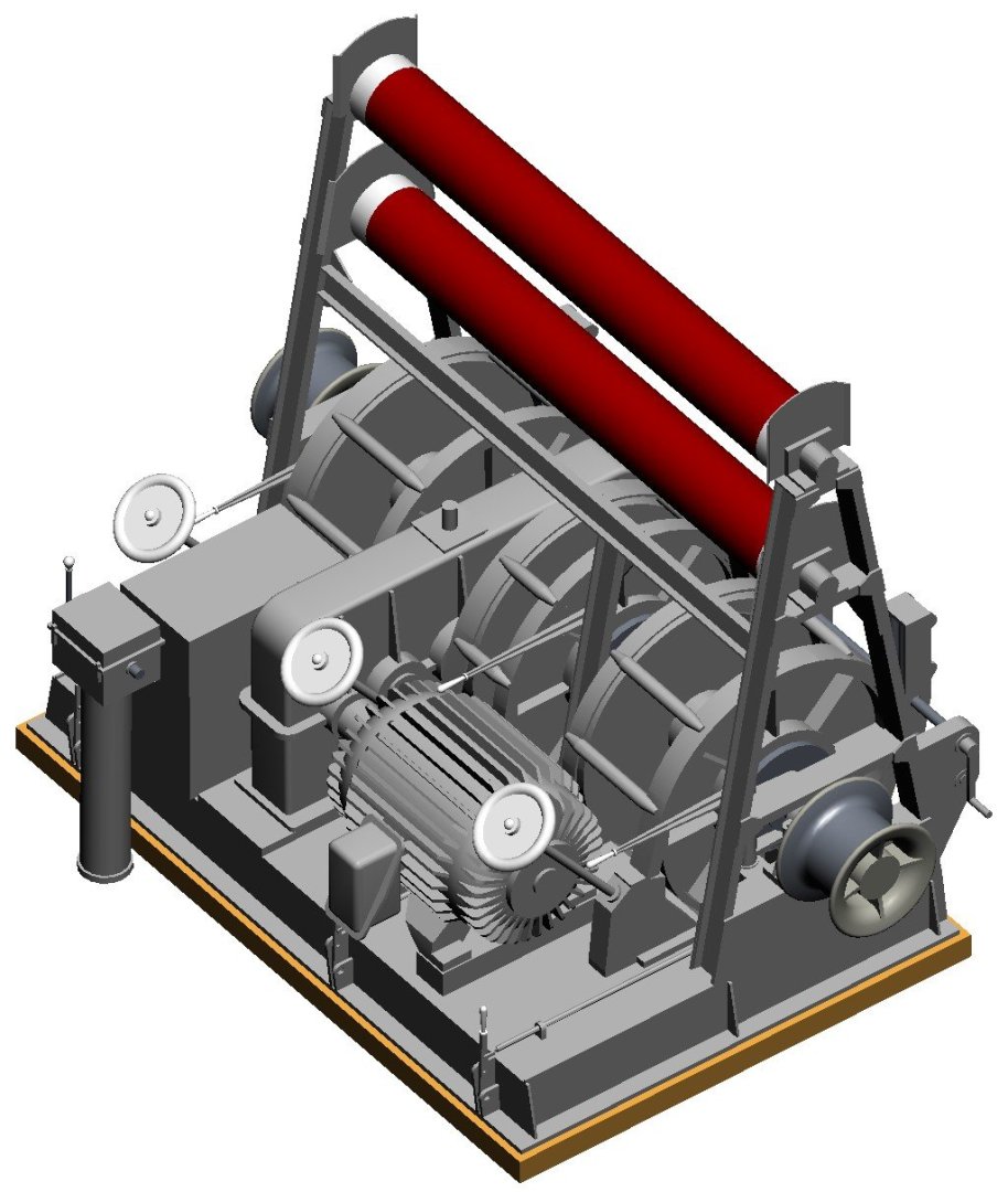
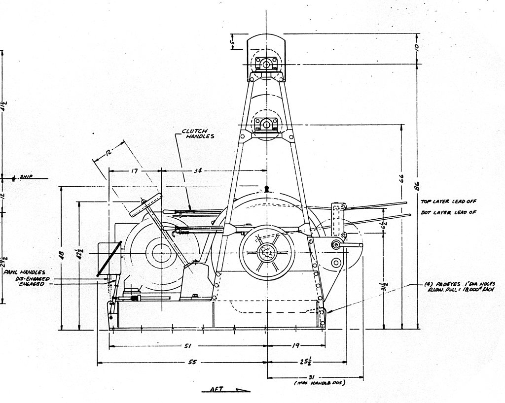
John, Tom and Gary, Thanks. The plans are pretty good, but a large number of dimensions are not given and have to be determined by careful measurements from printed drawings and scaling compared to dimensions shown on the drawings. But that's a LOT better than "photoguestimatiion" using measurements from photos! But I did run into a problem. One blueprint shows the winch control stand at the forward port corner of the winch. Another shows it on the fore side of the winch between the left two brake wheels (white in the images). These images show the two different positions for the control stand. The three white brake wheels are on the forward side of the winch, and the cables from the winch streamed out from the aft side. If the control stand was at the port corner it would be directly in line with the port gypsy head, and that would interfere with using the gypsy to pull on ropes and cables. None of the photos I have show the control stand clearly, but one that I took while we were streaming minesweep gear does show the white knob on the control stand handle to the right of the port side white brake wheel. So it appears the stand was in front of the winch and not at the port forward corner. But I am not certain where it was. And the photo may show the stand rotated around the vertical 180 degrees from the position shown here, with the handle on the inboard side. But that would put the stand right in front of the brake wheel, making it hard to reach! I will probably put it in the front, with the final position determined by what looks best. The control stand regulated the motor speed. The motor drove a series of step down gears in the long gear box with the rounded corners. The gear box turned the main shaft with the two gypsy heads on the ends for winching ropes and cables, etc. Each cable reel had a brake band around the outside of one side of the spool (inside a protective cover). The brake wheels (white) tightened and loosened the brake bands. Each reel also had a clutch that rotated with the main shaft. To engage the reel the long horizontal handle beside the brake wheel was pulled to the side, pressing the rotating clutch disk against a clutch plate on the side of the reel. The vertical "pawl handle" below the brake wheel was pushed forward to engage a locking pawl against teeth on one side of the reel to lock it in place.

- 464 replies
-
- 7
-

-

-
- minesweeper
- Cape
- (and 1 more)
-
Bruce, Good luck. I just did a patent search for the winches on the MSI with no luck. The new "advanced" search page is totally screwed up, with a bunch of overlapping windows that hide the search text entry box. Ad the simple search page won't let you look for things with more than one word in the name - like company names! Patent searches have always been a tedious process because you really don't know what the title may be. But if you find anything be sure to look at the previous patents listed in the newer patent application. This can lead you to other related patents.
-
A good source of plans for winches is the US Patent Office. When I was making my CLG-5 CAD model I started searching through patents and found an amazing number of patents for things on the ship, including a couple of the winches. The patents have drawings that helped me figure out how to model the parts. If you know the manufacturer you can limit the search. Of course if you know the patent number - often molded into cast parts or on an attached label - you are home free. There are patents and drawings for things you would never expect. I found the patents for the Talos guided missile (101 pages) and missile launcher! The Tarter and Terrier missiles and launchers are also there. I would have thought these would be classified!
-
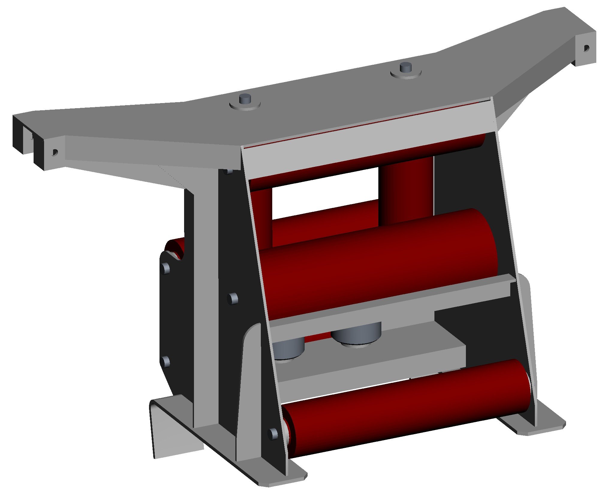
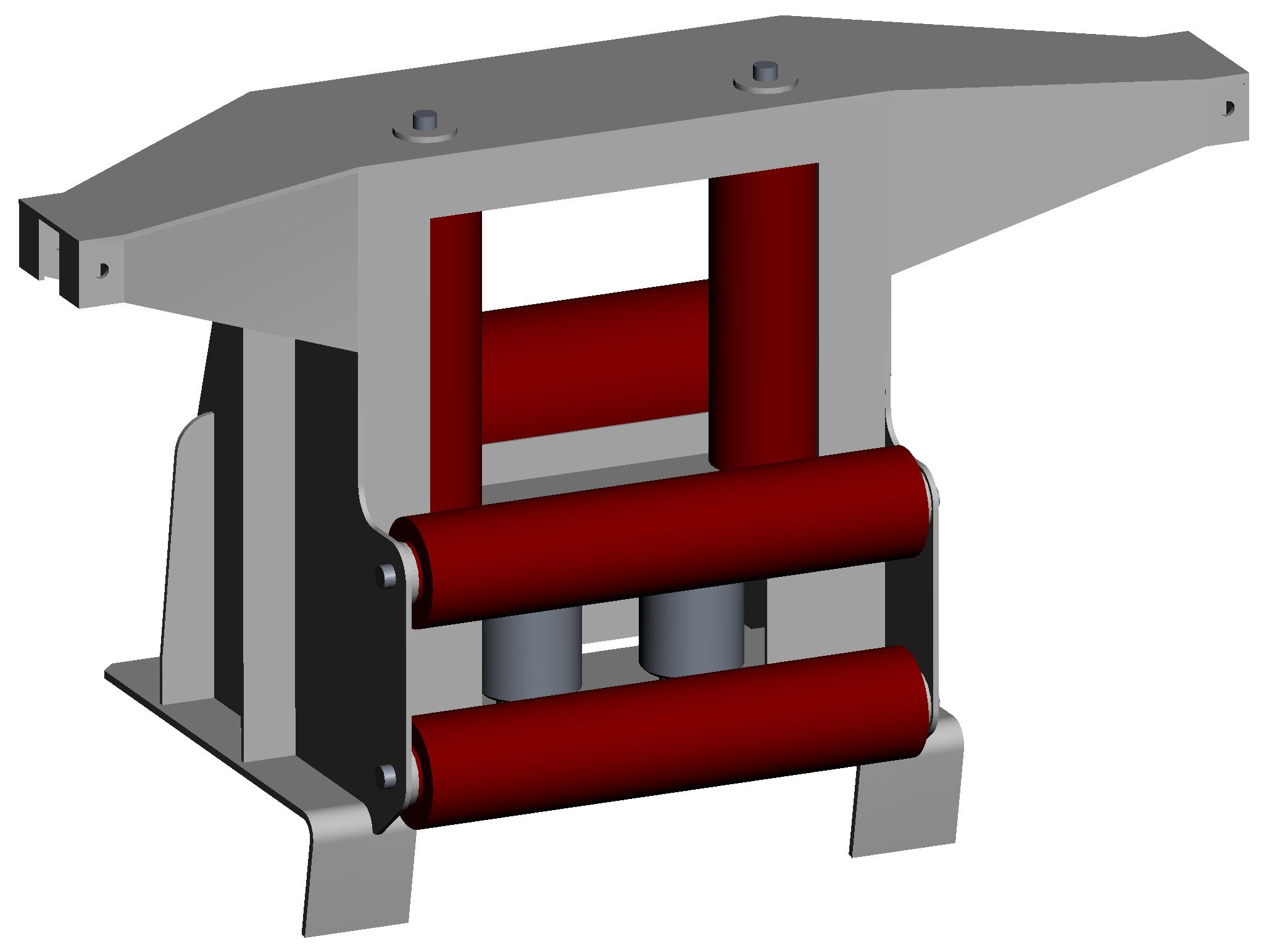
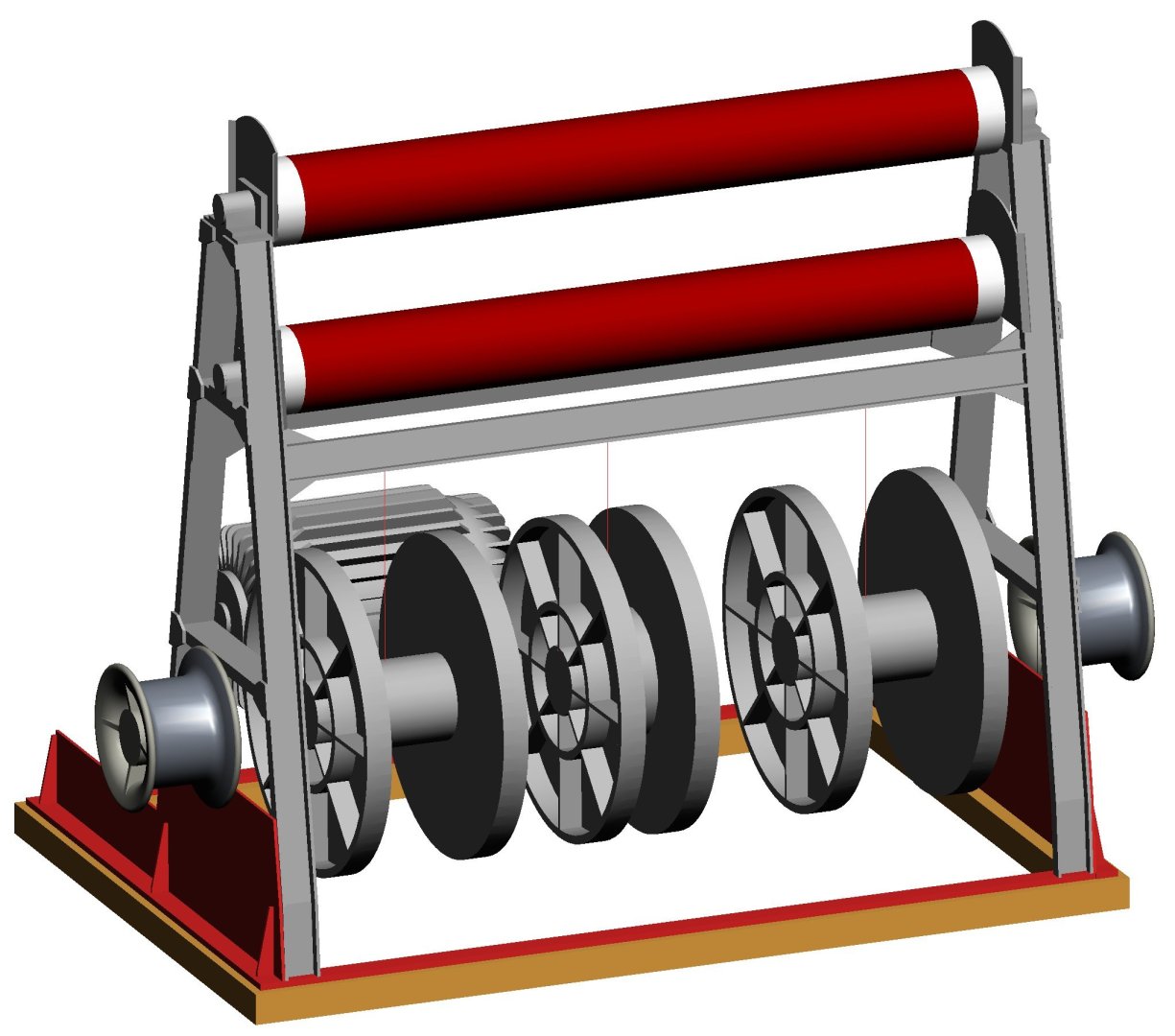
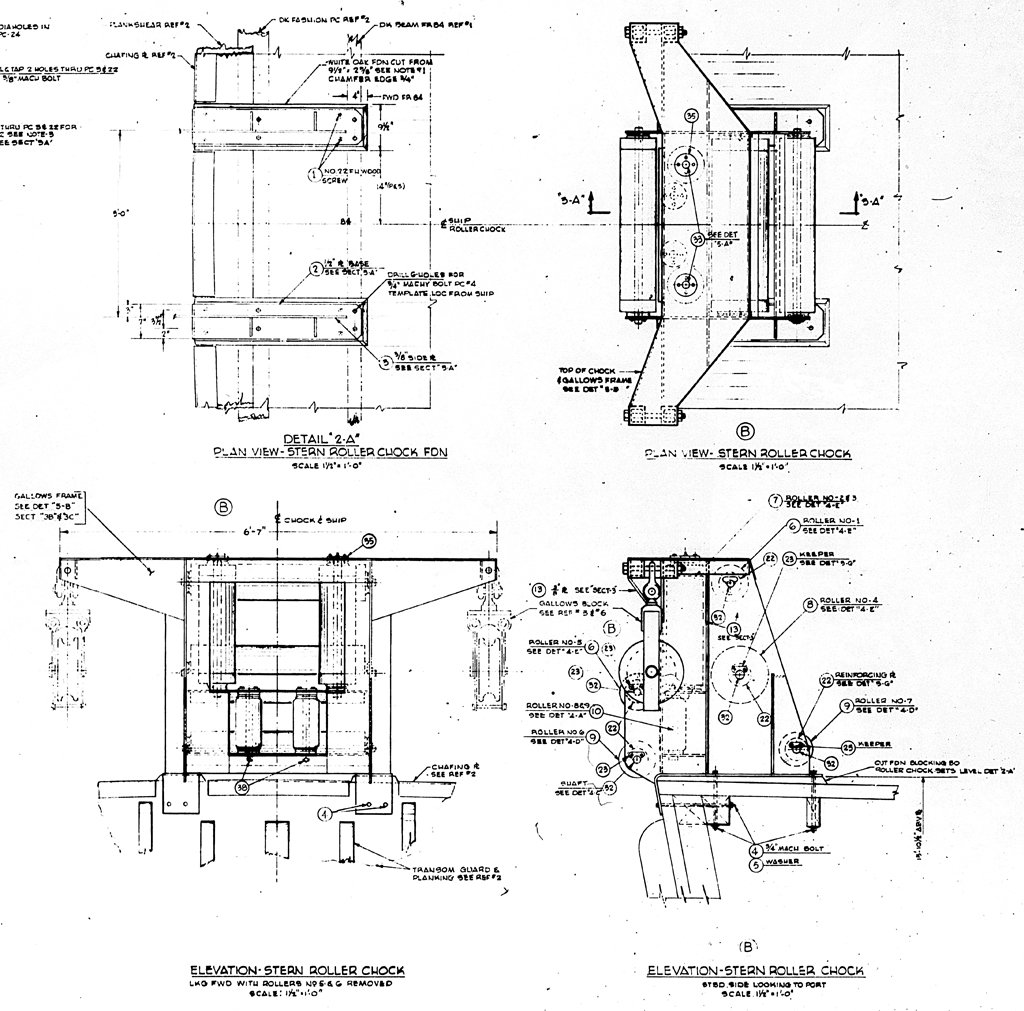
I am about ready to start planking the deck. But before starting that I have been making drawings of the deck fittings (deck furniture in the olden days) to determine what parts I need to have made from 0.005 inch (0.13 mm) brass with photo etching. Here are some examples. This is part of the blueprint for the stern roller chock. All of the minesweeping cables pass through the rollers or blocks attached to the "arms" of the top piece. This is just a small part of a large blueprint that gives the dimensions of all individual parts and a complete parts list. From this I made a CAD drawing of the assembly, and from it I can make 2D scale drawings of all the parts. I will make the pieces from 0.010 and 0.015 inch (0.25 mm and 0.4 mm) brass and solder them together. Some of the assemblies are more challenging. Here is a side drawing of the minesweeping winch (for towed sweeps to clear moored mines). I have top and end drawings as well. However, these drawings only give dimensions for the entire assembly, to be used for planning the mounting arrangement on the deck. No detailed and dimensioned drawings of individual parts are given, and there is no parts list. So I have to do a lot of measuring and calculating to guess the dimensions of all the parts not shown. I do have some photos, but they don't show many parts of the assembly. Here are pictures of how far I have gotten so far. The light brown parts are the wooden mounting base that sits on the deck. The red parts are work in progress for the metal base of the winch. The gray parts are finished. And the rollers on top are close to the natural colors of the reddish-brown polyester coating on the nonmagnetic metal rollers. This assembly sits forward of the stern roller chock and aft of the much larger winches and reels for the magtail (magnetic mine sweep cable) and the acoustic mine sweep cable (another very complex assembly!). The magnetic and acoustic sweep cables ride on the two large rollers at the top of the frame. The three large reels below are for the two long cables (left and right) to the pigs (floats) for the towed sweeps for cutting the cables of moored mines. The narrower center reel is for a shorter cable that tows a "kite" close behind the ship that pulls the moored sweep cables down deep just aft of the stern so the cables carrying the mine cable cutters will run under the mines to cut their mooring cables. All of these cables run through the stern roller chocks shown above. I do have separate detailed dimensioned drawings of the winch motor, and it is perhaps the most complex part of the assembly. But I have simplified it greatly, leaving off details of bolts and screws. On the model the motor will be about 0.73 inch (18.5 mm) long so the tiny details are too small to make. The whole winch assembly will be 1.7 inch (43 mm) high, 2.2 inch (56 mm) wide and 1.5 inch (37 mm) long. Most of the parts will be made of brass, but I may 3D print the gypsy heads (if I had a lathe I could turn them out of brass). It will be a nice little model in itself. There are about 30 separate deck fittings on the model, so I am just getting started!


- 464 replies
-
- 14
-
-
-
- minesweeper
- Cape
- (and 1 more)
-
I found these discussions about seniority and rank in the early U.S. navy very interesting. Today in the U.S. Navy (well, at least in the 1970s) seniority within a rank was determined by the date of an officer's commissioning. And that leads to a sea story. The USS Oklahoma City CLG-5 (my ship) was operating in the Gulf of Tonkin at Yankee Station off North Vietnam where the aircraft carriers hung out. The OK City was 7th Fleet flagship, and the current COMSEVENTH Admiral was an airdale (aviator) and liked to hang out with his flyboy buddies. So we sometimes drove the admiral over to the carriers and hung around while he visited. One morning I went up on deck for Officer's Call at 0800. As I poked my head up through the scuttle I was looking at the bow of an aircraft carrier bearing down on us on our starboard side! Constant bearing and decreasing range - collision course. That is NOT a place any OOD would put his ship! Any vessel crossing on your starboard bow has the right of way (Rules of the Road). I remembered that we lost a destroyer just a couple years earlier because the OOD turned the wrong way and crossed the carrier's bow. The front of the destroyer forward of the bridge was sliced off and immediately sank, taking all hands (Officer's Quarters) in the bow with it. The stern was saved but was towed to Portland, Oregon, and scrapped. I remember seeing it there in the scrapping yard a few years later. The carrier would have sliced the Okie Boat in half like a knife through butter. Afterward I asked the fellow on watch as OOD what happened. Our Captain was greatly impressed with his personal importance (sound familiar?). However, his command of the 7th Fleet flagship was only the second time he had been at sea. Most of his career had been the command of an LMD (Large Mahogany Desk) in Washington, DC. He never drove the ship, and I'm not sure he really knew the pointed end from the blunt end (bow and stern). Even the senior officers in the crew were unimpressed. When the carrier came along crossing our bow the OOD wanted to turn astern and allow the carrier to pass ahead, which is the normal thing to do. But the Captain stopped him, and told the Quartermaster on watch to get the Seniority List for Captains in the U.S. Navy. All this time the carrier was approaching on a collision course. The Captain told the Quartermaster to determine the carrier Captain's date of rank. Old LMD had the earliest date of rank, so he ordered the signalmen to send a message telling the carrier to give way because he was the senior officer! The carrier did make a turn to pass behind us and passed dangerously close! We could have all been killed because of that megalomaniac's conceit!
-
I am always leery of small parts cut out of thin wood sheets. All woods have a grain, and break easily along the grain. The smaller the part the more likely it will break when handling. Well, maybe European boxwood is an exception, but I have no experience with it. Castello/Costello boxwood is really nice for carving but I haven't pressed my luck with thin pieces. I always use thin "aircraft" plywood for pieces like these hearts. The alternating grain on each layer makes it MUCH stronger and less prone to breaking. I guess you got 3D printed resin parts from Syren by the look of the picture. My experience with 3D printed resin parts is that they are very brittle and break easily. But Chuck has done a lot of research and maybe he is using a better resin than I have used. I have used Syren's older wooden "kits" and they are excellent! They are made up of three thin layers of Castello boxwood. After gluing them together they are very strong, like plywood. And they have the nice groove around the edge for the rope to fit into. If Chuck is still making these wooden kits the next time I need hearts I will buy them instead of the resin parts.
-
I bought some 1/64 x 5/32 boxwood made by Mt Albert Scale Lumber in Canada. They have a good selection of small "lumber." 0.0156" x 0.03125" (1/64 x 1/32), 0.03125" x 0.03125" (1/32 x 1/32), etc. I bought about 175 pieces of 1/64" x 5/32" basswood and the dimensions were very consistent in all pieces. They threw in a few extra pieces too. I actually purchased it from Fast Tracks Hobbyworks, Inc. https://handlaidtrack.com/shop/?v=0b3b97fa6688&wpf_filter_cat_list_1=2902
-
I use a quilting iron - made for ironing narrow "tabbing" around the edges of quilting pieces. It works great for taking the wrinkles out of silkspan - they recommend the lowest heat setting for the silkspan. The quilting iron is also excellent for bending wooden planking. https://modelshipworld.com/topic/19611-albatros-by-dr-pr-finished-mantua-scale-148-revenue-cutter-kitbash-about-1815/?do=findComment&comment=1039363 https://modelshipworld.com/topic/37060-uss-cape-msi-2-by-dr-pr-148-inshore-minesweeper/?do=findComment&comment=1075263
-
Pretty cool tool: drilling positioner
Dr PR replied to CPDDET's topic in Modeling tools and Workshop Equipment
I would find it more useful if it went down to 0.5 mm (0.020") and 0.25 mm (0.010"). -
Gold solder for brass
Dr PR replied to Richard Braithwaite's topic in Metal Work, Soldering and Metal Fittings
That is an interesting assembly! Looks like the main body could be one large piece wrapped around at the front, with top and bottom pieces added. Then you would just need to add the "fins" and "C" pieces on the sides. If you are worried about the solder stain around joints you could just flow solder over all of the surfaces. Then everything would be "stained." That would give the model an impressive golden ram. But it would use a lot more expensive solder. -
convert 2D Autocad to STL for 3D printing
Dr PR replied to Johnny Mike's topic in 3D-Printing and Laser-Cutting.
JM, 2D files are usually just lines and maybe planes. These are zero thickness objects and cannot be converted to STL (or any other 3D file). You will have to redraw the objects, creating 3D solids. If you do create 3D solids DWG files (with no 2D objects like lines and planes) they can be converted to STL or OBJ files that can be printed. 2D and 3D drawing have almost nothing in common. 2D drawings are made on a virtual flat surface, like sketching on paper. 3D modeling happens in a virtual 3D universe NOTHING like the 2D plane. You have to build 3D objects like you would create real things out of wood, metal or clay. It is an entirely different working environment! -
Gold solder for brass
Dr PR replied to Richard Braithwaite's topic in Metal Work, Soldering and Metal Fittings
tmj is right about the solder stain on brass. Solder dissolves into the brass, so no amount of polishing can eliminate the solder color. I was curious how the people who make brass model train engines and cars manage to solder everything together without any visible solder stain. They use resistance soldering mostly for anything that will be visible after the model is finished. Very small (1 mm x 1 mm or smaller) bits of solder foil are sandwiched between the parts and the electrodes are connected/placed on the two parts. A quick zap of current through the pieces melts the solder and it flows into the joint but no where else. Maybe a tiny solder fillet is visible at the junction with a magnifier but otherwise no solder is visible. You can make your own solder foil by hammering ordinary round solder flat. It takes a lot of planning to make the brass parts fit tightly before soldering, but the results are beautiful. I have done something similar with an ordinary soldering iron where one side of the joint will be hidden inside the model. I just lightly tin each side of the joint to be soldered and then put the two pieces together and heat them until the solder melts. Sometimes I just clamp the two pieces together and brush some liquid citric acid based flux into the joint (I prefer this flux because it smells like oranges). Then I place some small diameter solder against the inside or hidden side of the joint and heat it with a soldering iron. The solder flows into the joint where the flux is but no further, with none visible on the outside or visible joint seam. But this can leave some solder stain on the inside where the soldering iron touched the brass. -
This is a very pretty model and nicely built. I am enjoying your build and waiting to see how you make the masts and rigging.
-
I seem to recall reading somewhere that the copper plating fit between the keel and the wormshoe (false keel). The wormshoe was a sacrificial piece to protect the keel and was replaced when necessary. It looks like the bottom of the keel was coppered first, then the wormshoe was stapled to the keel. Then the copper plating was placed on the keel. I can't tell from the photos, but perhaps the angled strip along the joint between the keel and garboard strake is there, but under the plates on the keel and those on the garboard strake?
- 5 replies
-
- 2
-
-
- copper plates
- Braak
- (and 1 more)
-
Mark, The 1/8 x 1/8 inch strips are boxwood. This could be anything since it is hidden inside the deckhouse. The deckhouse sides and decks are SIG 1/16 inch plywood - I don't know what type of wood. The deck planks are 1/16 x 1/16 inch strips. That is to scale, but is pretty small. Nibbing will be pretty tricky. The grout was 1/4 inch (6 mm) on the ship. That comes out to about 0.005 inch at 1:48 scale. I think thin black paper would make a nice clean grout, but that means working with a LOT of thin paper strips! I did this on the schooner build. I have experimented with pencil on the sides of the strips, but it is inconsistent and pretty lame looking. Of course I could use some of the original calking goo we used on the Cape - I saved some in a bottle for use on models, and I even planked a model ship deck with it back in the 1970s! But it is extremely messy. No thanks, once is enough!
- 464 replies
-
- 5
-

-
-
- minesweeper
- Cape
- (and 1 more)
-
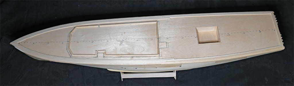
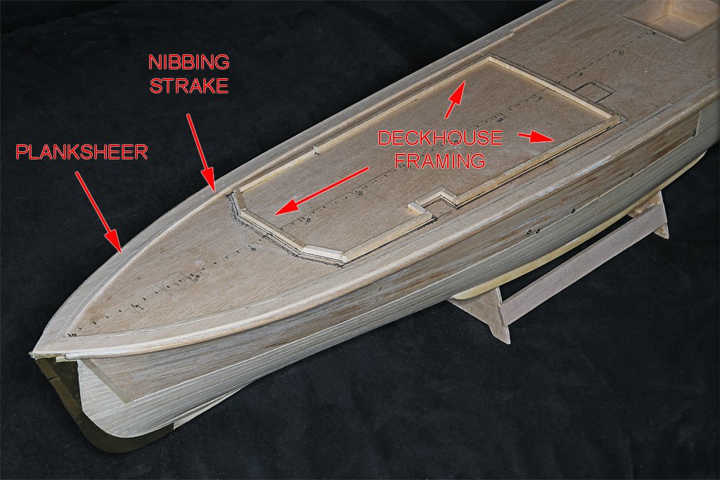
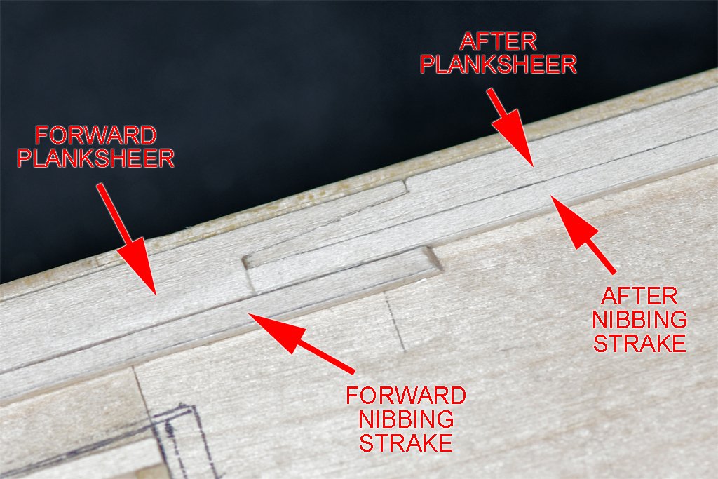
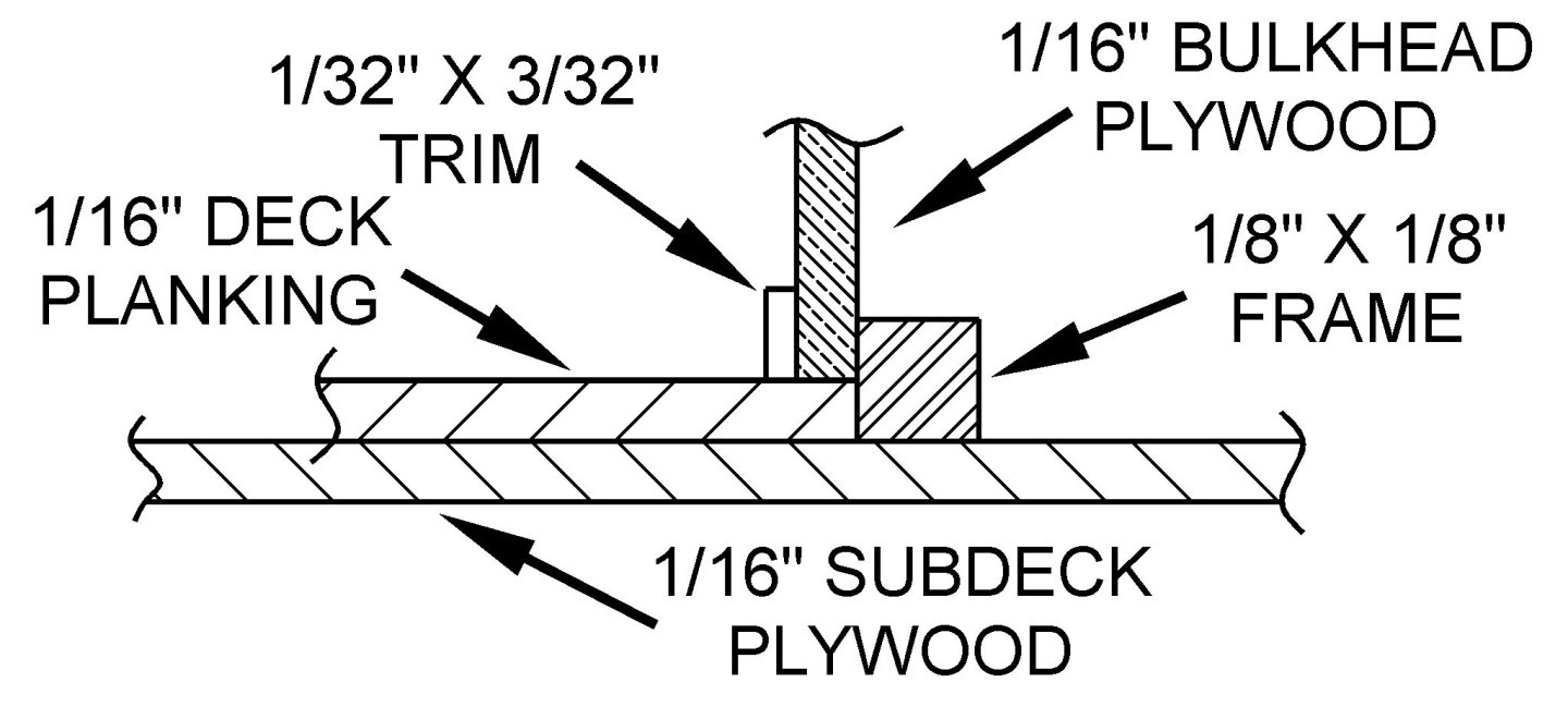
I have some progress to report. I have installed the planksheers and nibbing strakes, and framing for the deckhouse. The planksheer forms the outboard edges of the decking. It is wide up forward where the bulwark frames attach to the planksheer. Aft of the bulwark the planksheer is narrower. Inboard of the planksheer is a separate nibbing strake that the deck planking is nibbed into. This strake is the same width fore and aft. The deckhouse framing is 1/8 x 1/8 inch (3.2 x 3.2 mm) basswood strips glued to the plywood subdeck. My plan is to lay the 1/16 inch (1.6 mm) deck planks against the frame. Then the 1/16 inch (1.6 mm) thick deckhouse side bulkheads will be glued to the frame and deck planks. The final touch will be a 1/32 x 3/32 inch (0.8 x 2.4 mm) trim piece around the base of the deck house sides. This arrangement is convenient because I will not have to be too careful in cutting and shaping the ends of the deck planks or the base of the bulkheads. The trim piece will hide any small irregularities. Actually this trim piece should be almost triangular, with the apex at the top against the deckhouse sides. On the real ship the deck house sides rested on a trapezoidal base piece that rested on the deck planks (they extended into the interior of the deck house). If I can figure out a consistent way to reshape the trim pieces so the top is narrower, almost coming to a point, I will try to do this to mimic the original look. I have extra trim strips to experiment with. Murphy has already had a hand in this build (somehow this seems appropriate for the Cape). I made a 2D CAD drawing of the deck and deckhouse, and printed a paper template of the deck house and a frame scale. I used the frame scale to mark the centerline and frame positions on the sub deck and then positioned the deckhouse paper template so I could draw the outlines on the deck. But after I had done this I realized that the deckhouse was almost 1/4 inch (5 mm) too long! I checked all the CAD drawing dimensions against the blueprints, and they were OK. So I printed another template and it was too long! This was getting annoying, so I started looking at everything to find the problem. It was the printer driver! In the past the print scale has been saved with the drawing file - in this case it should be 1:1. But somewhere along the line (I recently installed a new driver for the Brother printer) this got set to "fit to page" in the driver, and the space between print margins on a 8 1/2 x 11 inch sheet is about 1/4 inch wider than the actual length of the deck house. And to complicate things more I had made a mistake in the spacing between two frames on the printed frame scale, and this compounded the error! If you look closely at the photos you can see multiple lines drawn on the subdeck. With the correct frame scale drawn on the deck, and the correct scale deckhouse template everything seems to be working out correctly now. There is an interesting problem where the wide and narrow plankshear pieces are scarfed together midships. The forward planksheer is the same width as the after planksheer and nibbing strake, as shown in this picture. The forward nibbing strake overlaps the after nibbing strake. The blueprints show the deck planks nibbed into the two nibbing strakes here, and even possibly into the aft end of the forward planksheer. This isn't shown clearly, and the drawing notes say nothing about this. The deck planks are parallel to the center line (the blueprint notes are clear about this) and not curved along the deck edge, So there will be some long nibs here, in a pretty complex pattern. Right now I don't know how this will turn out!
- 464 replies
-
- 10
-
-
-
- minesweeper
- Cape
- (and 1 more)
-
Paul, It is hard to say how close the deck color in the photos is to reality. These were old color slides and there was some slight greenish color shift. That was corrected in the edited version I posted. It had rained (or heavy fog) the day I took the photos so the deck was damp, and that can cause the wood to appear a darker color. But it is clear that the decks had not been scrubbed or holystoned and bleached in a LONG time - if ever. It was a working ship and a lot of dirt and tree bark must have been ground in to the wood over the years. Scrubbing the decks to satisfy some admiral probably was never done! Also, I don't know if the museum had applied any type of coating to preserve the wood. On the other hand, since we will never know what the actual color was, using the color in the photos is a step better than a wild guess!
-
Paul, Maybe it is because I have walked the Wapama's decks and am very fond of this ship, I would vote for painting the model. The fully detailed and realistically painted model is as close as we can get to visiting the ship now.
-
If the fiber optic isn't bright enough you could buy some small surface mount LEDs. Glue them on a thin wood strip (paper or any non-conductor) end to end, cathode to anode. Then add a drop of solder at the ends to connect them. Do it quickly and the wood/paper won't scorch too much. LEDs have a certain voltage drop each at the design operating current. Just divide your power supply voltage by the LED voltage drop to get how many LEDs you should put in series in a single circuit. Add a current limiting resistor somewhere it the circuit between the LED strip and the power supply. You can experiment to control the brightness (and the amount of heat generated) by varying the series resistor. At larger scales you can glue a thin white translucent plastic strip over the LEDs to diffuse the light and complete the "fluorescent" lighting fixture.
-
Without sails the jackstaff is most appropriate.