


Arthur Wayne
-
Posts
103 -
Joined
-
Last visited
Content Type
Profiles
Forums
Gallery
Events
Posts posted by Arthur Wayne
-
-
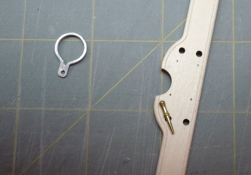
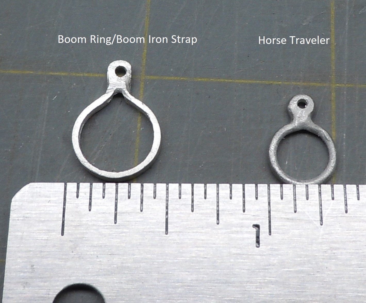
With the hull pretty much done, I'm starting to move on with the mast/bowsprit etc. Dr PS brought this up in his build log, the instruction manual misidentifies 2 parts that could cause confusion. The boom ring and horse traveler are identified in the instruction manual as being the opposite of each other so the below picture is informational to anyone building this kit and correctly identifies the 2 parts.

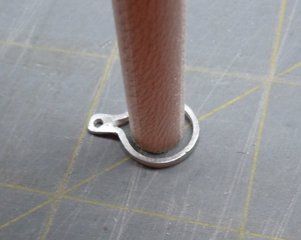
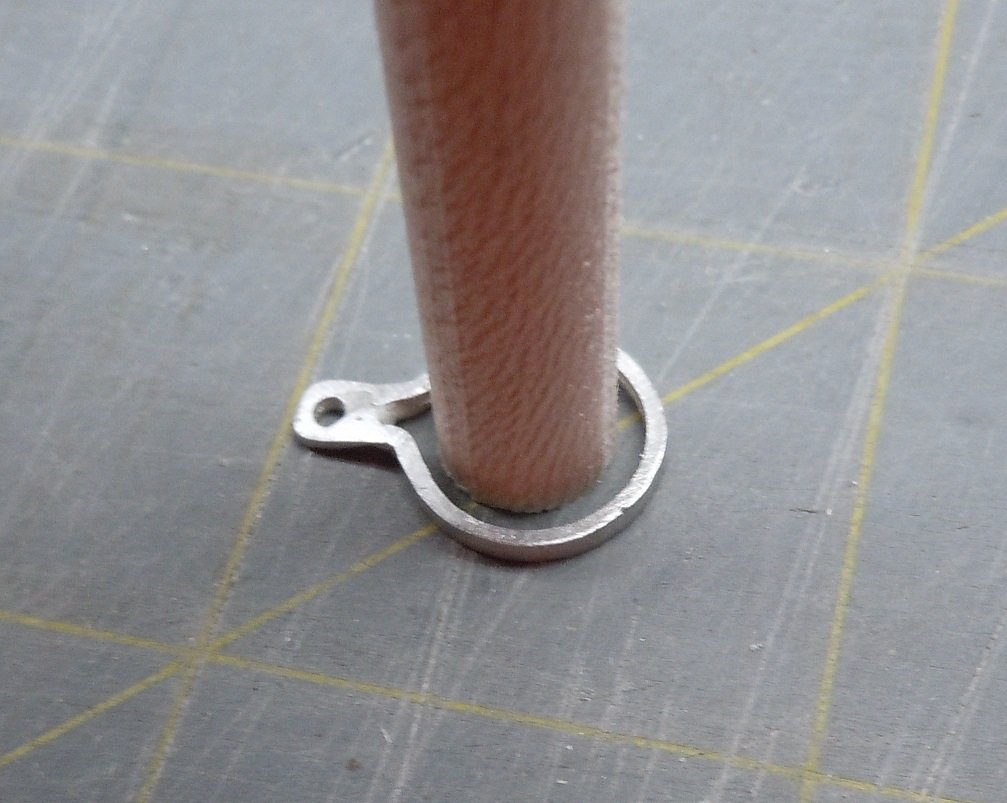
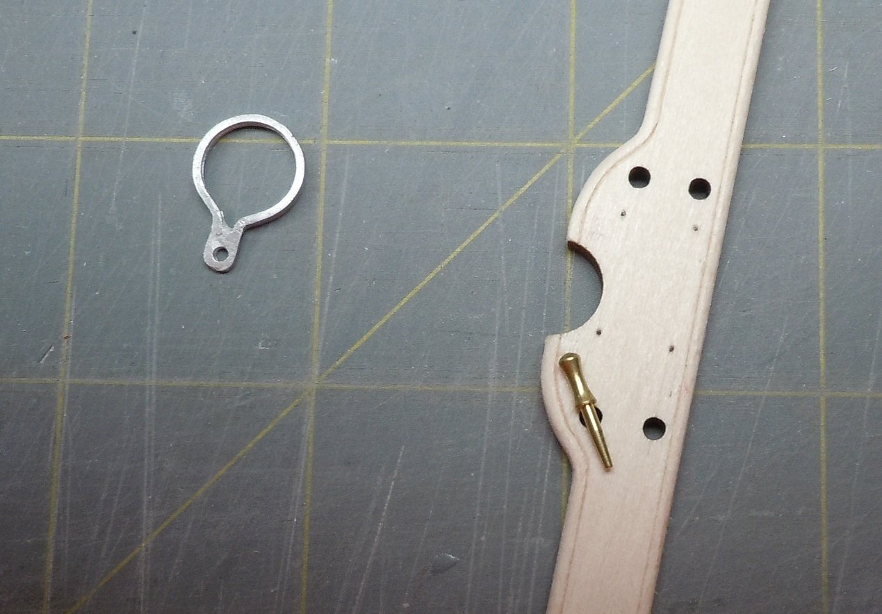
Early on the build I noticed the cutout in the mast thwart was 3/8" diameter whereas the mast is 5/16". I couldn't get the mast straps to snug up to the mast using the kit thwart so I made a new mast thwart. Now that I am starting to shape the mast I discovered the boom ring is way too big to fit the 5/16" mast, in fact it's inside diameter is 3/8". Below is kit provided 5/16" mast set with the boom ring. Oddly, the mast foot is just a hair over 5/16" which it should be so the mast slips in with a tiny bit of wiggle room. As it stands, the room ring will not be usable for me but making one from brass shouldn't be too big of a task. Another option would be to enlarge the hole in the mast foot (too late for me to do it's already installed) and obtain/make your own mast with a 3/8" diameter at the bottom.

It's also worth pointing out the kit supplied belaying pins are quite nice. Unfortunately the laser cut holes for the belaying pins on the supplied mast thwart are just a hair smaller than the widest point in the belaying pin. The pins when inserted flop all around, I don't think they will work with these holes when rigging the model as they will always be cocked over at an angle. Reason #2 I made a replacement mast thwart.
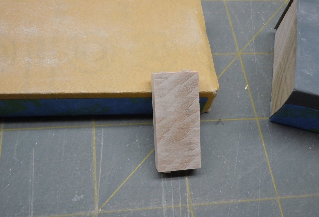
In the mean time, I prepared the thwarts. I wanted to keep these parts as straight and square as possible so I inserted 2 pieces of the dowel provided for the thwarts into a stack of thwart mounts and sanded the whole shebang at one time. This helped keep them square and true.
Thanks for looking, I appreciate any comments or criticisms.
-
-
Paul, I think I see the confusion now. The Cast Metal Parts diagram on page 8 misnamed the horse traveler and the boom ring, essentially swapping names with the associated parts. The boom ring is the largest ring of all the parts. The horse traveler inside diameter is only about 1/4" while the boom ring is 3/8". There's no way you could get the mast down to 1/4" diameter, 3" above the floor and have it look the way it does on the prototype. Here's the boom ring with the 5/16" mast placed inside to show how big it is.
-
Paul you have run into the main mast issue! The Horse Traveler has a round cross section whereas the Boom Iron Strap has a flat cross section. I was actually going to cover this in my next post on my build log. If you go to a larger dowel it will cause the following issues:
1. The Mast Foot hole is 5/16" diameter. You will need to step a 3/8" dowel down to 5/16" to fit and that will not look right IMHO, or make a new mast foot.
2. The Mast Support Iron Bracket fits the 5/16" dowel. It will not fit around a larger dowel no matter how you try to bend it. You will need to make one from scratch.
Oddly enough, the Mast Thwart cutout for the mast is laser cut for a 3/8" diameter mast. Also, the Boom Iron Strap has an inside diameter of 3/8". I don't know how this happened on the kit side of the house, xken reported that the manufacturer supplied parts he built the prototype from didn't have these issues.
When I discovered this I also noticed that the belaying pins are about .000001" larger than the laser cut holes in the mast thwart and will never work correctly unless they are glued in with epoxy in an upright position. So..... I concluded the easiest fix would be to create a new mast thwart with a 5/16" cutout and smaller belaying pin holes. This allows the use of the kit supplied mast, mast foot and mast support iron bracket. I am also making a replacement Boom Iron Strap from brass tube which is every easy to make. It seemed to me to be least amount of work approach to this issue.
I'll be interested to see what you come up with, I'm sure you sort it out.
-
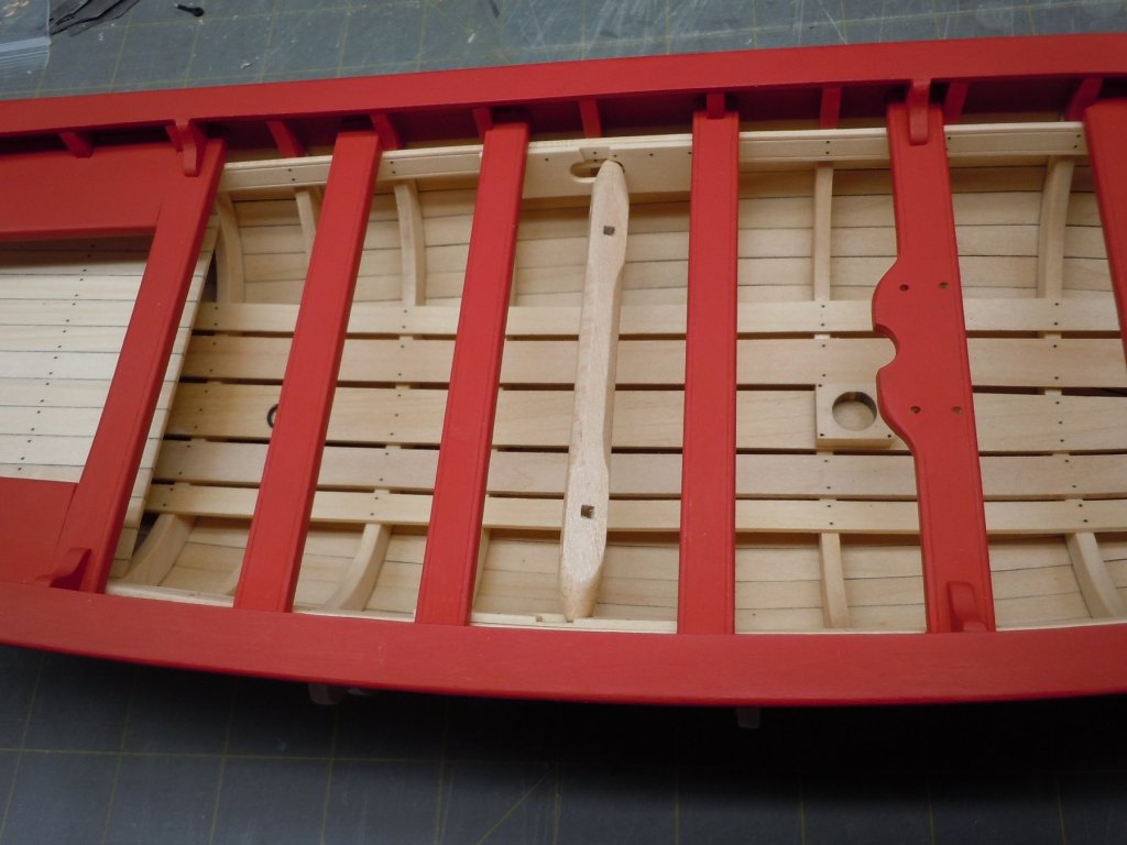
At the recommendation of Bob Cleek in his post earlier I replaced my eyebolts with the beefier kit supplied version. I also installed the mast bracket, which I drilled through and nailed to the thwart. I also added the bolt detail to the mast foot. The kit supplied nails were too thick or the laser cut holes to small and close to the edge to drill out so, I used straight pins as a substitute.

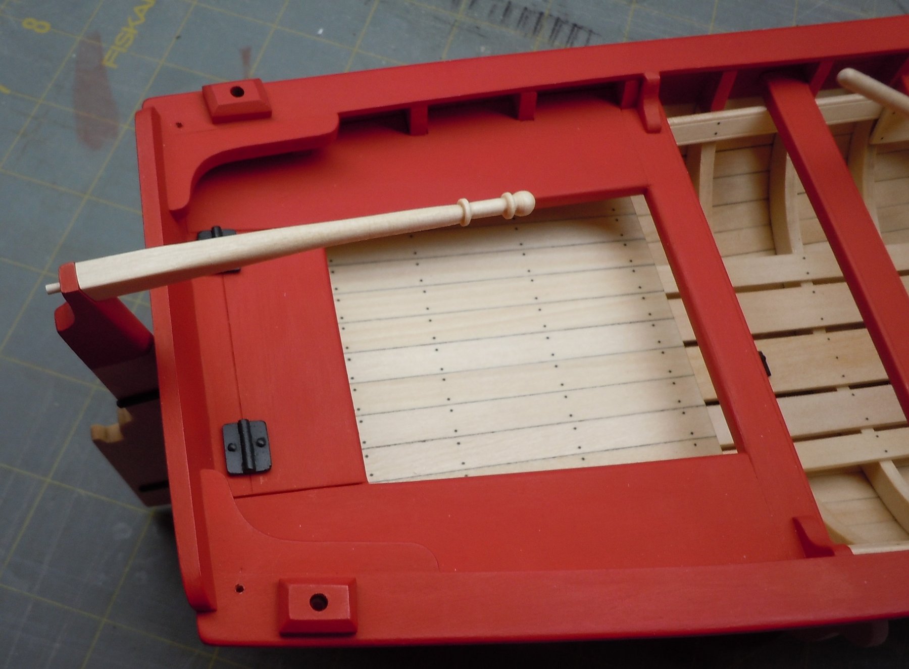
I also got around to adding the locker hinges, I added bolt detail to them small nails. I also trimmed my tiller to the final length, it's held in place by the pin and a little friction. I may or may not glue it permanently later.

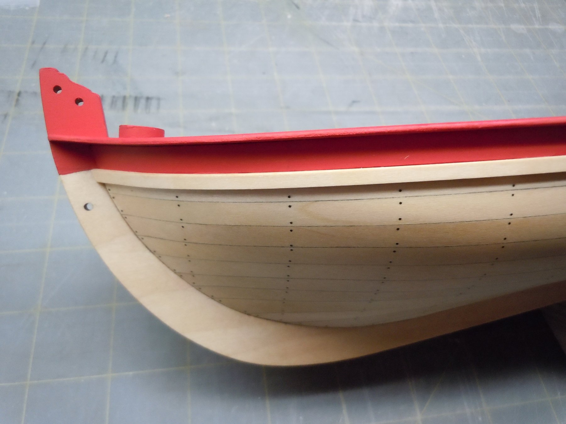
With the rudder sealed with wipe on poly and painted, I installed the eyebolt in the transom. The eyebolt shank is square so I filed it round so that it would plug into the transom without leaving a gap. Once the hole was drilled I painted the transom and then installed painted eyebolt, the pintles and the gudgeon. I chose to install the photo etch decorations at this stage, versus after the boat has had it's mast and rigging installed. I was worried this would be more difficult to make look right than it was. I painted the etch parts while they were still on the fret with Krylon Metallic Brass. I laid on 4 light coats and then several heavy coats. This helped soften the edges of the photo edge brass which makes them look less like photo etched brass. I used thin CA wicked at the edge of each etched part in small strategic spots as recommended by the instructions. Once they were all in place I went back with paint and touched up the small glossy spots of CA. I started with the transom first.
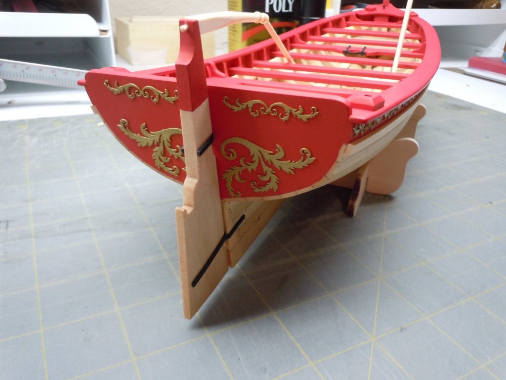
I then added the etched parts to the top strake. I wasn't sure I would like how this would look and considered leaving the etch parts off however I think it makes the model look very nice and less monotonous.
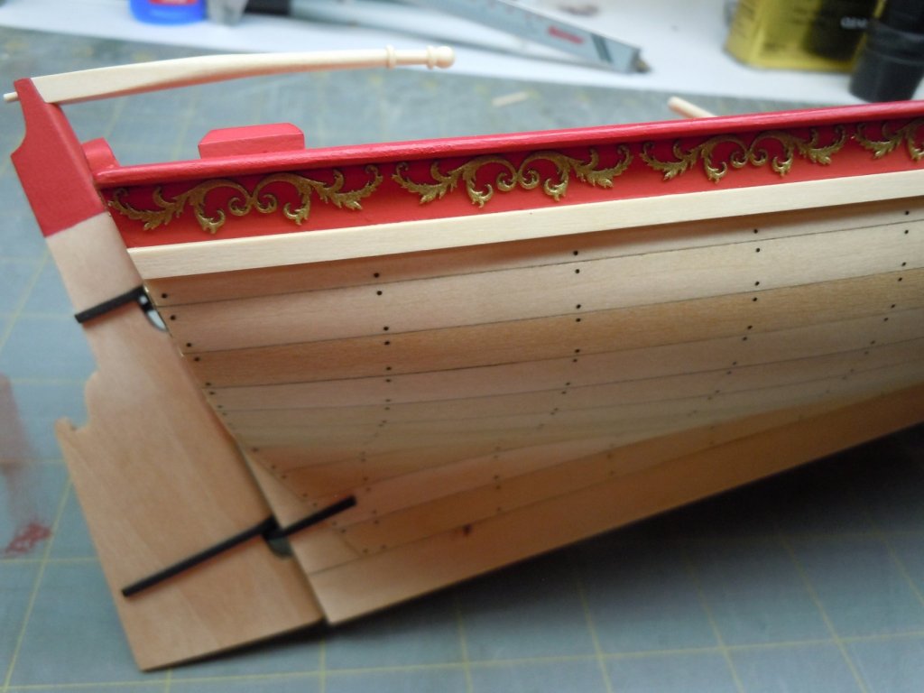
I thought about painting just the top strake and transom black, I think that would really make this model pop. Truth be told I didn't want to lay on more layers of paint and risk getting black paint oozing through to the inside so I chickened out and stuck with the red. All in all I still think it's a nice detail to add to the model and well worth the effort.
Thanks for looking, I appreciate any constructive comments or criticisms.
-
Paul amazing progress, do you bother with eating and sleeping ever? What pewter black did you use? I searched multiple times for such a product but never found anything I was confident would work.
-
-
-
Well Paul looks like you not only caught up to me but are pulling in the lead! Nice work on the paint job, looks like you're planning to paint the lower hull as well?
-
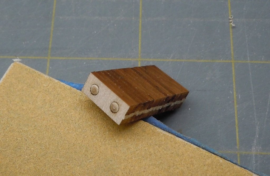
Very cool Paul, wish I would have seen this a few weeks ago! I never considered mounting a scraper like this, I'm going to give it a shot on the next profile job I need to do. Was your kit supplied brass PE scraper twice as small as it should have been as well?
-
Paul, I got what you're saying. I don't think it gets squared off. If you look at the photo of the kit prototype xken built in post #35 above, it looks like round brass rod to me. Also check out the Medway Longboat, the horse is made from round stock I believe.
-
Paul I'm just going to an aircraft qualification course, this will be my 7th so it's duck soup and a welcome break from duties.
7 hours ago, Dr PS said:A question on the build, is the horse really square? At 5/64”, there will be nothing left of the rod. I am tempted to just leave it round. Do you know what the prototype was? I have been scouring the builds but have not found anything yet.
I am adding and edit to this post as I went back in your log and found the entry by xken and his horse I think appears to be round and not square. I will proceed as I was inclined to do and go with round unless I find out differently.
I think you're talking about the tiller? It's made from 5/64" square stock and is square where it attaches to the rudder but tapers and becomes round on the other end. If you're talking about the horse (the bar that spans the rear cockpit seat just in front of the transom) that is made from round brass rod.
-
xken built the prototype and all I can say is, he's a wizard! This particular piece of wood was soft and pithy so my first attempt was a no-go. Hopefully you'll have better results. As for the square holes, they aren't as easy as they look are they? I would have redone this part but I expect it would have came out the same but thanks for the compliments. I see you've just about caught up to me Paul, you are cranking right along!
Yes I'm leaving the Army thinks I've been here long enough, I'm off to school later this summer and will find out where I'm gonna land sometime before I finish in December. We have really enjoyed Texas and will miss it a lot, it's a really cool state to live in.
-
Micro Update: I made the windlass handles from the kit supplied wood. I deviated from the kit instructions which have you create a tenon on the end of the handle to be inserted into the mortise on the windlass. I chose to create handles similar to those Chuck created for his Medway Longboat and are also apparent in the contemporary museum models in his post. This seems a simpler solution to me that makes sense in the real world, that's my rationale for the KISS approach. At any rate I simply rounded the square kit stock with my drill and sanded the flat ends to a slight taper to fit the windlass. I'm still debating on painting the top half of the handles red per the kit instructions.
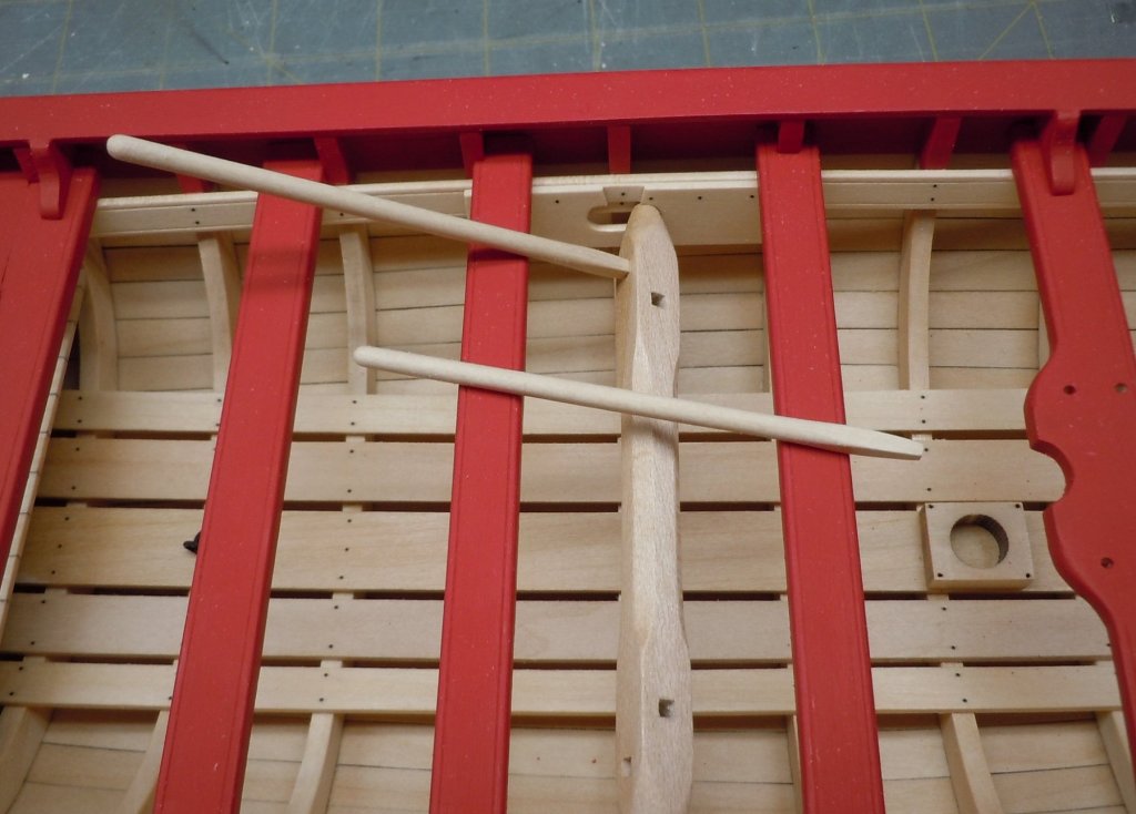
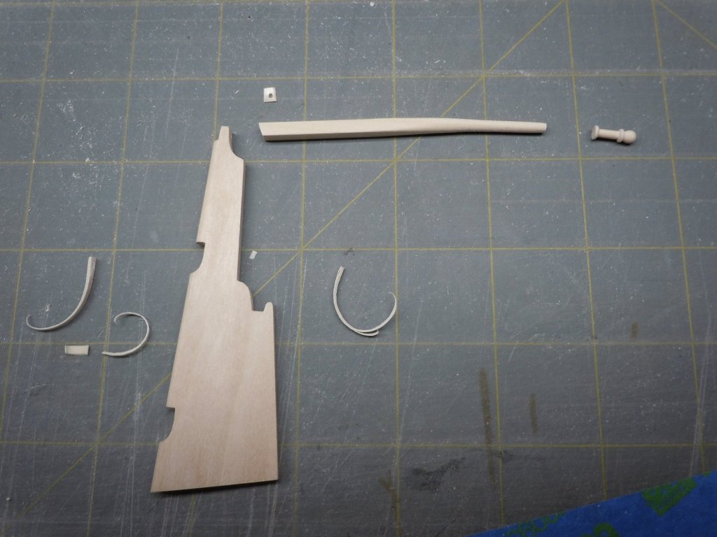
I've moved onto the rudder assembly. After sanding away the lovely char laser cutting gits us with, I tapered the rudder and rounded the leading edge. I then created the first of 2 tillers. The first tiller was made according to the instructions, nothing difficult to write about however the tiny tenon that I created was snapped off at some point only to be discovered after I finished shaping the hand grip. Round 2, I omitted the tenon and made the handle from a separate piece. It just happens that this particular piece of wood is very soft (almost like hard balsa), hand carving even with sharp blades was causing chunks to come loose. I opted to turn the handle using a cordless drill, Dremel and some sandpaper. I will pin it on the tiller with brass rod. I will also use a harder wood to create a tenon to affix the tiller to the rudder. I also just noticed in my photo below that the rudder is facing the wrong direction in relation to the tiller.
In between waiting for wipe on poly and paint to dry, I've been cleaning up all of the metal fittings which are now done and ready for paint. I just might have a fighting chance to finish this model before I move.
- BenD, Ryland Craze, JpR62 and 2 others
-
 5
5
-
As I understand it, the windlass wouldn't always be present on the boat but rather installed as needed. I've read reference to the boat and windlass being used to assist in retrieving the ships anchor, as well as being used as the "muscle" to hoist items from ship/dock to the boat for transport to the ship/dock.
-
I appreciate the insight and taking time to help out! As you surmised this is very easy to undo. I'll pull these out and set the kit supplied parts in place to see what looks better, I hope you will see the post and provide feedback.
-
The scraper is the one that came with the kit, it's the square with the notches on the brass PE sheet in the kit.
-
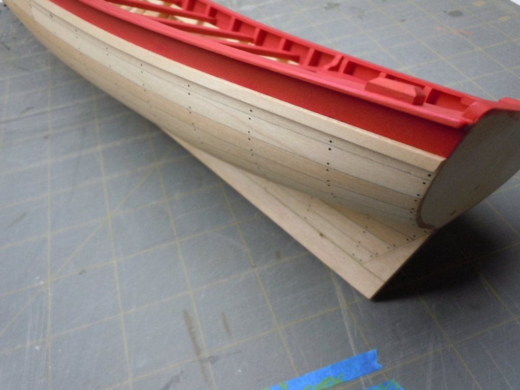
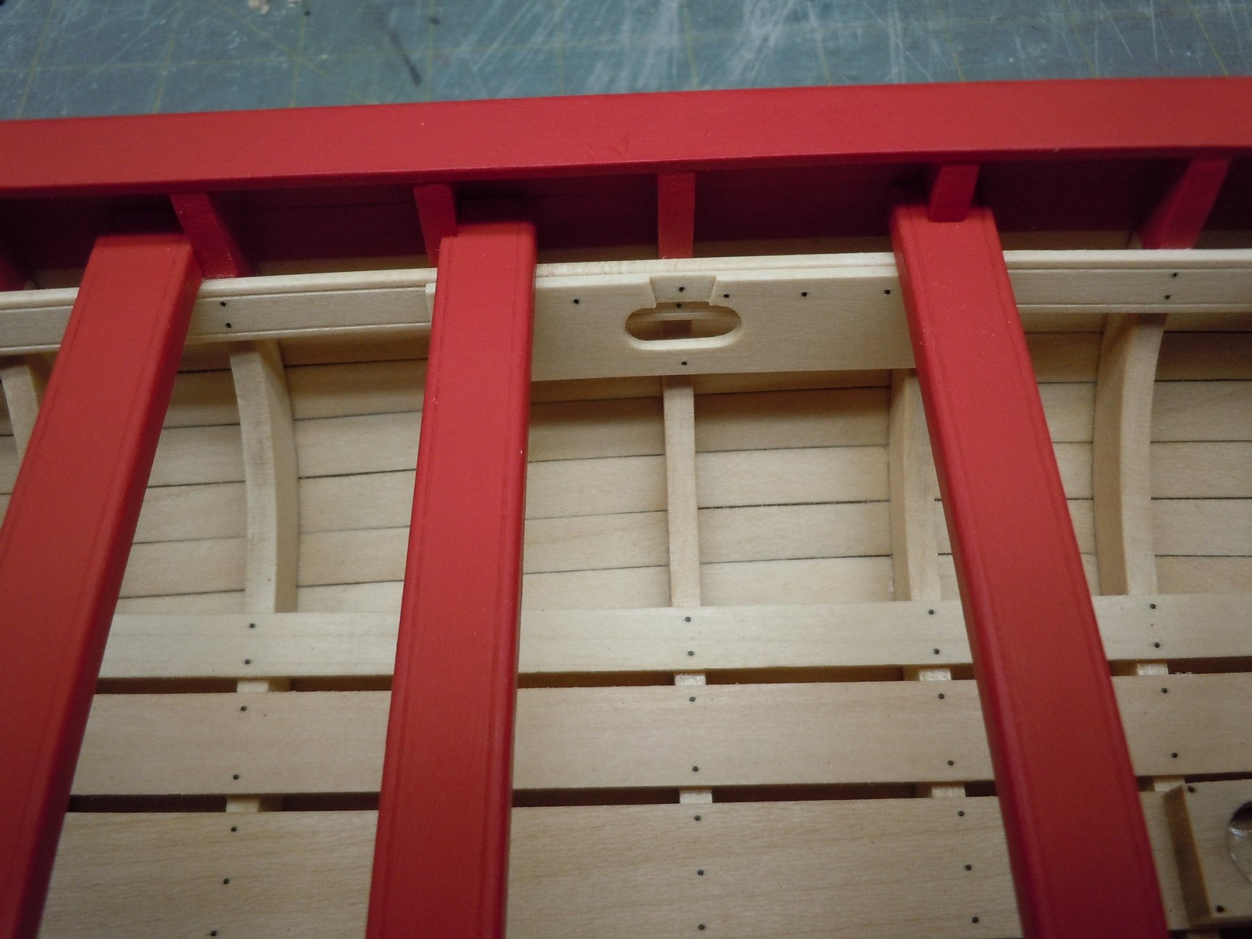
With the cap rail installed I was finally able to paint a number of coats on the thwarts, the cap rail and the exterior top strake. I skipped ahead in the instructions to add the rub rail. The rub rail is made from 1/8" x 1/8" strips shaped with a PE scraper included in the kit. Although the instructions call it half round, you can't make a square half (1/8" x 1/8" square stock) round. Additionally, the PE scraper half round is only 1/16" wide so it was unusable as is. I suspect this tool was included in the 1/48 scale kit and MS forgot to enlarge it 200%. Not the end of the world, it's easy enough to make another scraper which is what I did. I was unable to scrape a smooth consistent radius on the bass wood to my liking. I then experimented with alternatives and settled on making 1/8" wide by 1/16" strip. I terminated by rub rail flush with the transom. Once glued in place I brushed on a thin coat of wipe on poly.

Now it was time to make the windlass. As with much of this build Chuck's Medway Longboat is a source of inspiration and I chose to emulate his methods. I didn't care for affixing the windlass directly to the thwart risers with a brass pin for a variety of reasons. I chose to create a windlass mount similar to the Medway Longboat. I just drafted a plan with Adobe Illustrator and created my parts from 1/16" sheet. I pre-nailed the part and then just glued it in place.
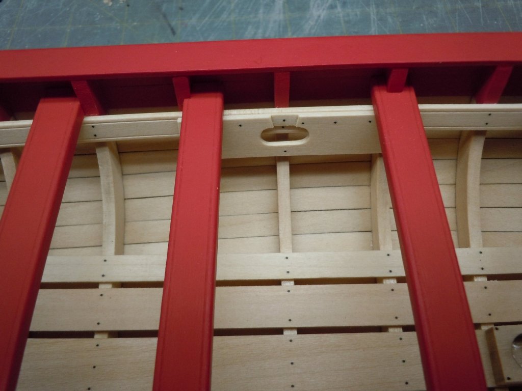
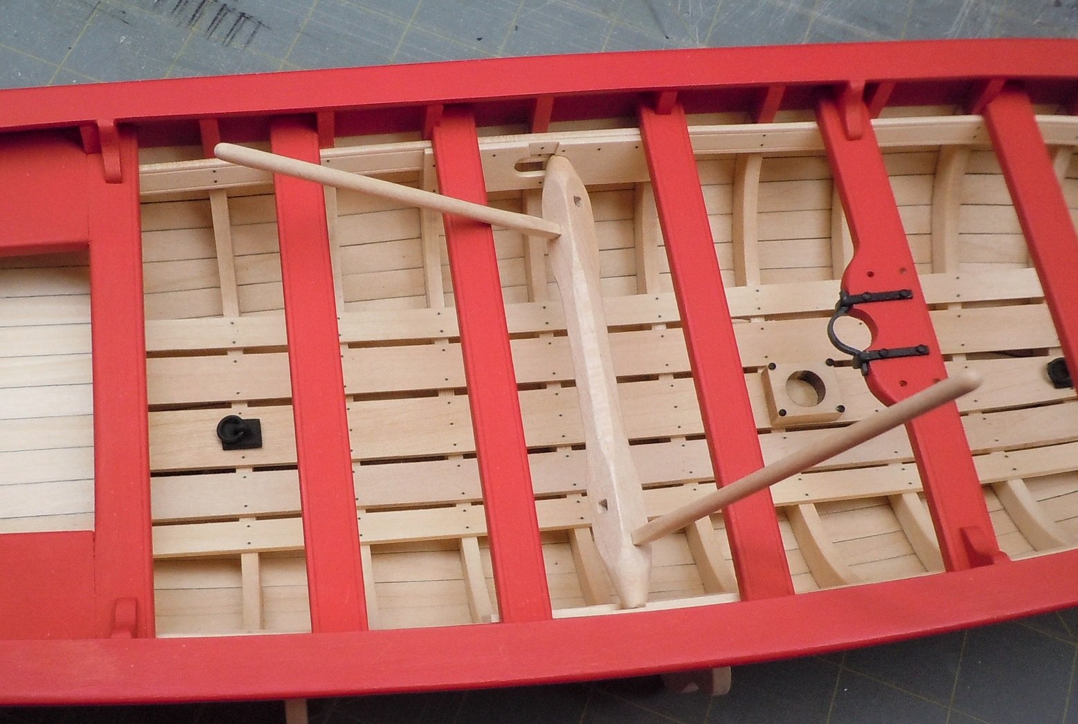
Next I added the lifting rings to the floor. I thought the kit supplied eyebolt mount was kind of chunky and the rings seemed like the brass rod used was slightly oversized. I elected to make my own eyebolts and lift ring from brass rod. After painting they were installed, I still need to touch up the brass where I scraped it off during installation.

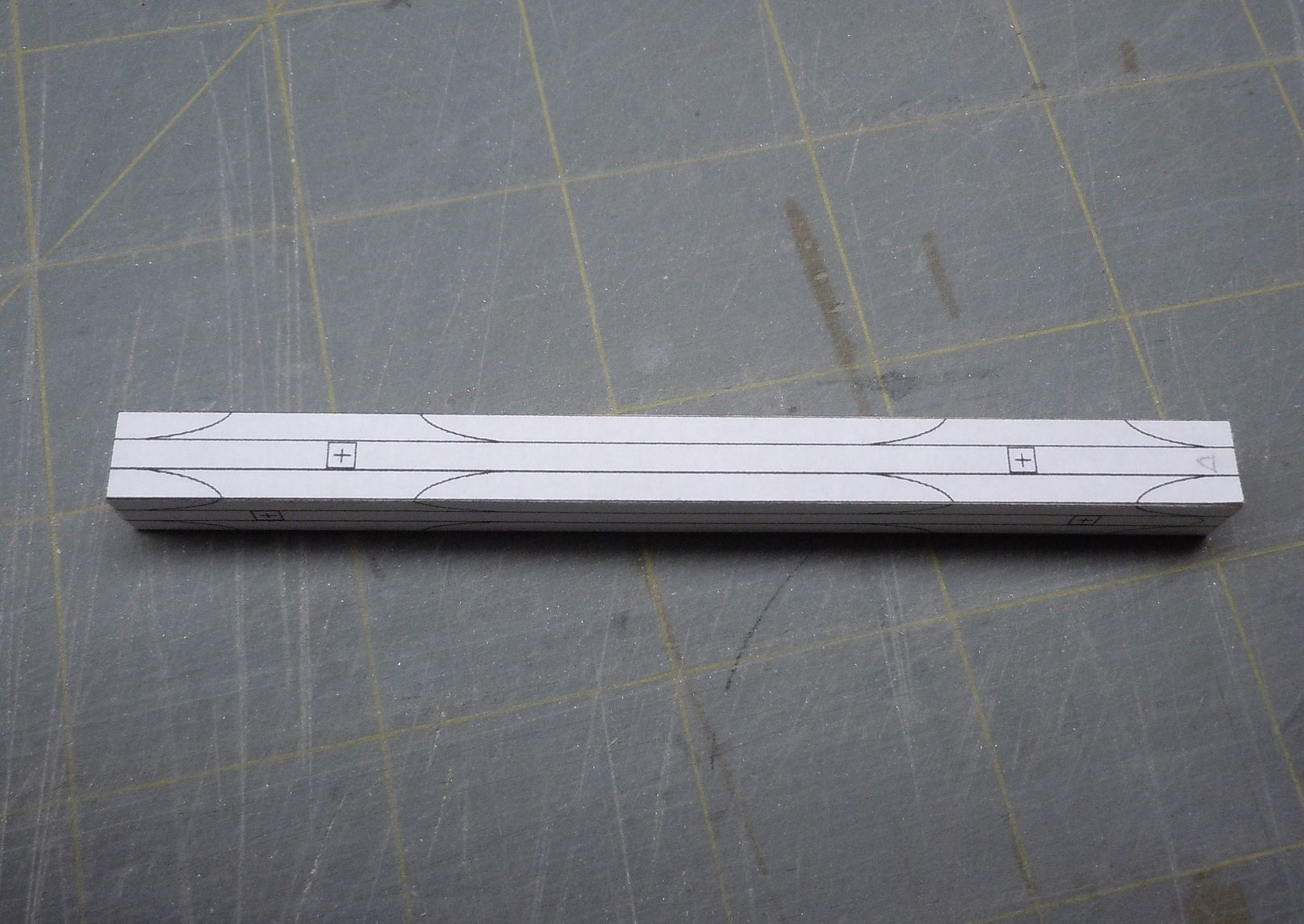
Next I made the windlass. Again borrowing from the Medway build I created a drawing in Illustrator, and used stick glue to affix the drawing to the kit supplied square stock.
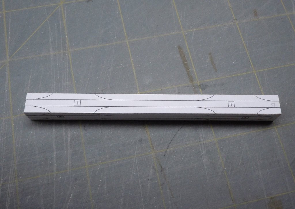
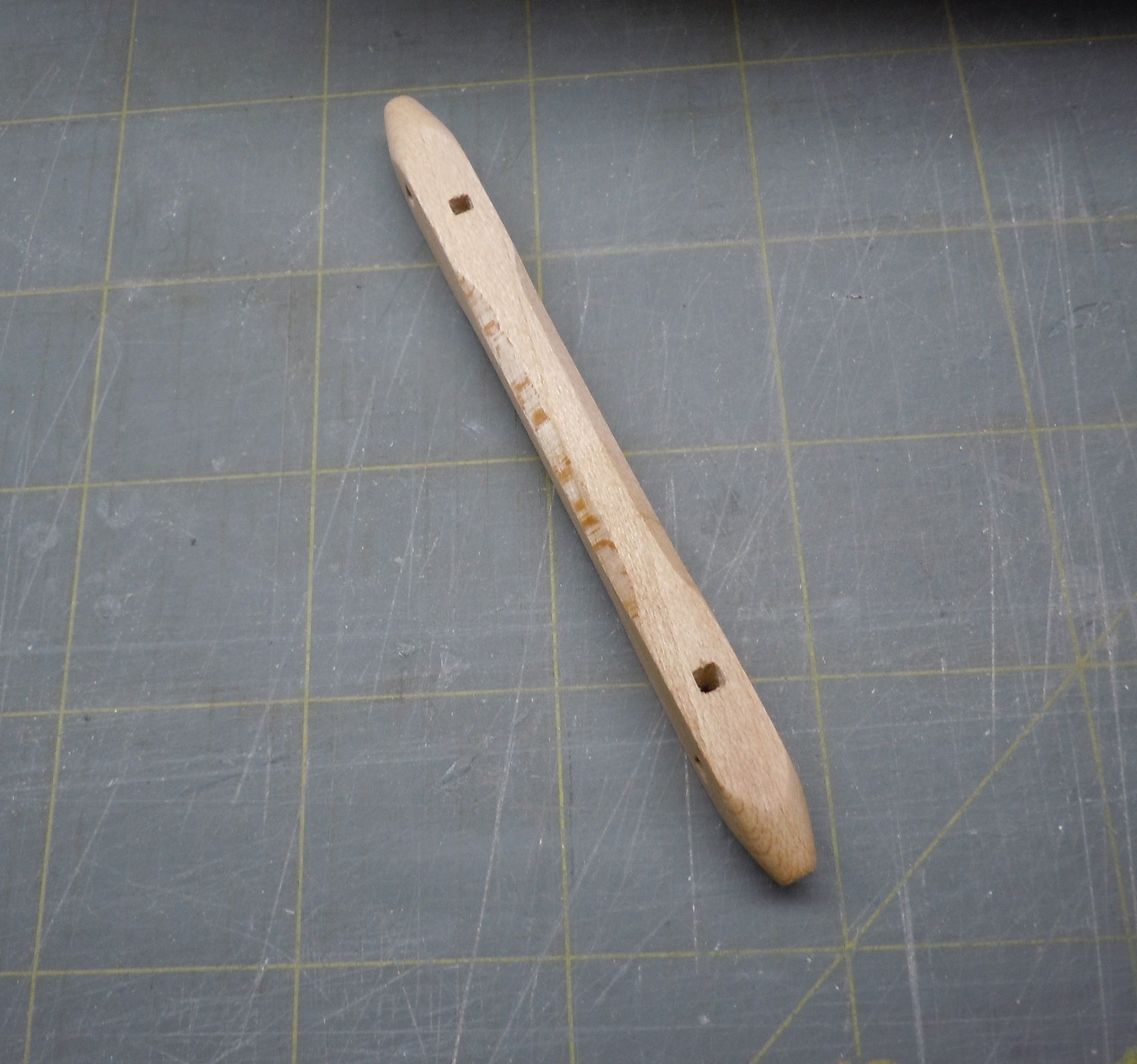
I used an #11 bladed to shaped the part which turned out to be much easier than expected. Once my carving was done I removed the paper template and, did my best to make round holes square and tapered the end to fit into the mount. When I was happy with the fit I final sanded the windlass and applied a coat of wipe on.

To my happiness and surprise, the windlass fit and is easily installed and removed!
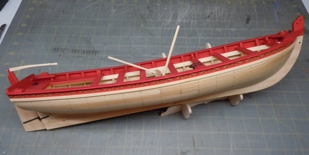
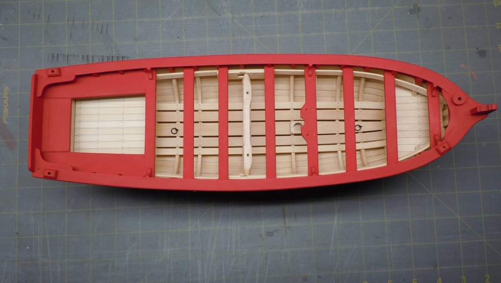
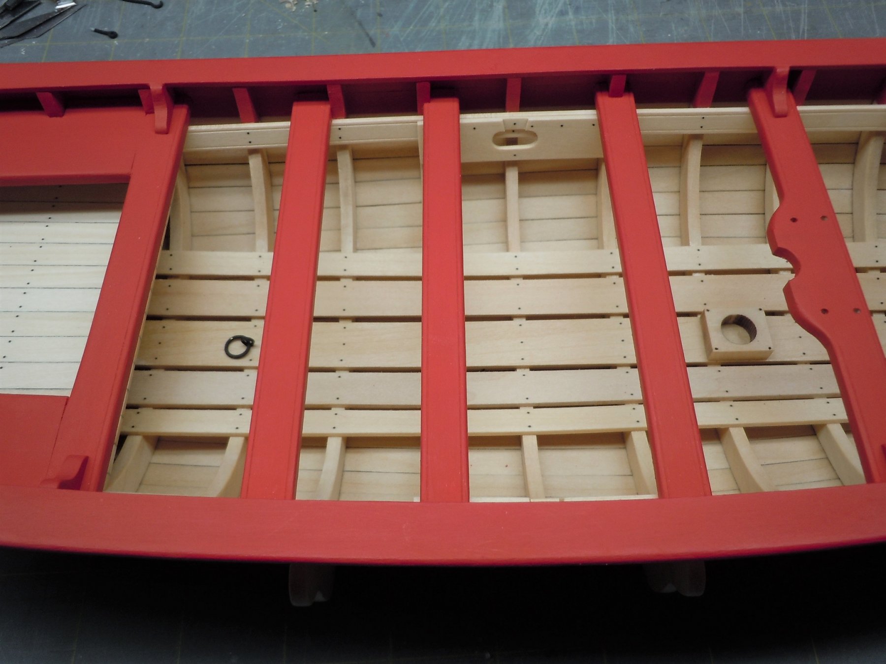
Finally a top view of the boat at this stage of construction. I'm working on the windlass handles now, and will tackle the rudder next. Thanks for looking!
-
Looking good Paul, you've almost caught up to me now!
-
Interesting stuff Paul. I'll be interested to see how your laser cut cockpit seats fit.
-
Looking great Paul, and I'm still positive you will finish before me. Where did you buy the surgical blades?
-
Your boat looks terrific! At this pace you're going to pass me by in another 2 weeks!!
-
-
xken, thanks for the reply. Not sure why I am having issues, maybe my kit was produced on a Friday afternoon? 😀 Another builder completed this kit here, you can see in his photos that the cockpit seats came up short for him as well. In any event it's not an insurmountable obstacle. Hopefully I don't come off as complaining, my intent is to help anyone building this kit not make the same mistakes I did.


18th Century Armed Longboat by Arthur Wayne - FINISHED - Model Shipways - Scale 1:24 - Small
in - Kit build logs for subjects built from 1751 - 1800
Posted
This may sound weird but I don't think it will look right that way. Besides that, my thwart and mast straps are already set for a 5/16" mast. It will be far easier for me to make a boom ring at this stage. Hopefully others building this kit notice this issue and can adjust the mast foot and procure a 3/8" mast, that would be the best solution to plan for. Had I noticed this early on, that's what I would have done. In all fairness, figuring things like this out is half the fun,.... I think.