iMustBeCrazy
-
Posts
976 -
Joined
-
Last visited
Content Type
Profiles
Forums
Gallery
Events
Everything posted by iMustBeCrazy
-
 I came across this pic of Police on the Thames which opens a new can of worms:
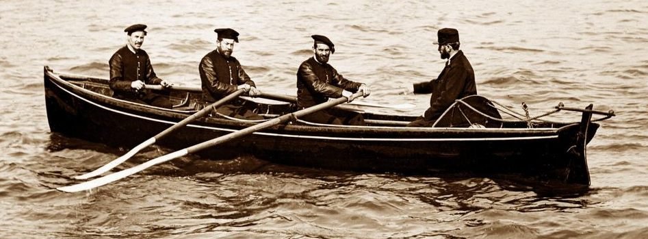
-
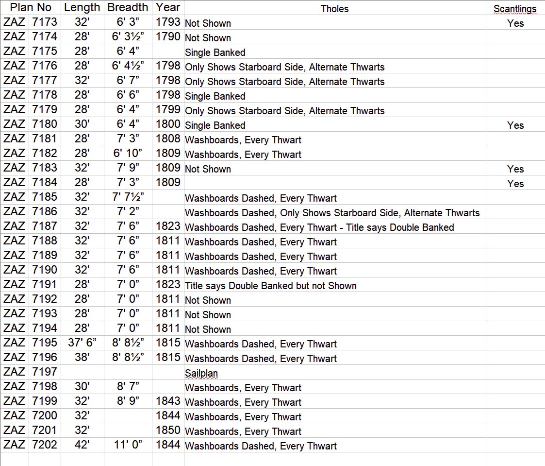
This is what I can come up with for pinnaces:
-
The problem is a lack of standards. There were no drafting text books so it was a case of doing as you were taught. Some drawings such as the one above may, for example, depict a half hull model while others the whole boat. When depicting the whole boat, sometimes objects the far side of the centreline are drawn dashed, sometimes solid. Sometimes extra details are depicted on the half breadth, sometimes not. Ultimately these drawings are not the engineering drawings of today, they are general guides backed up by scantling details and contracts which we rarely see. Or the might be right, but I don't think so.
-
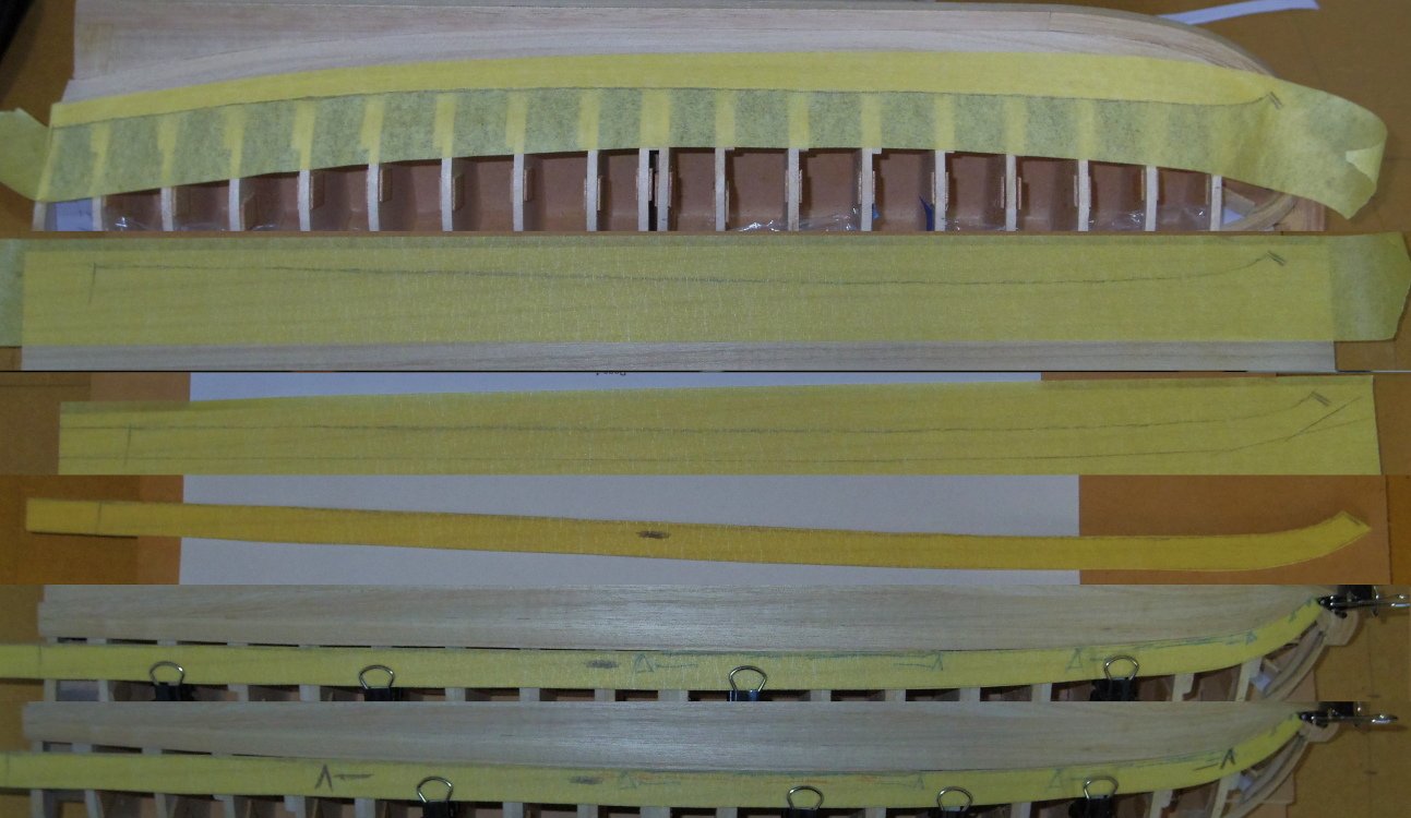
Alfredo, it has little to do with the number of planks, it is about the shape. (although narrower planks are easier to bend sideways). The kit planks are rectangular, mine are shaped (a bit like a ski, see the photo) to fit against the previous plank. This process is called 'spiling'. Spiling can be simulated by 'edge bending', forcing a plank to bend sideways with the use of heat, but wood doesn't like doing that. I find cutting the plank out of a wider piece of wood easier.
- 19 replies
-
- 2
-

-
- Bounty Boat
- OcCre
- (and 2 more)
-
G'day Alfredo, I think that, given you were trying to do 'correct' planking with the wood supplied, you've done quite a good job. First, a reminder that your planking is quite thin (I think 0.5mm) so it can't stand much sanding, go easy. For any very low areas try gluing another layer of planking over the top of the low area (matching colour and grain as best you can) then sanding it down to blend it in. This is so you don't sand too much off adjacent planks trying to match the low area. A little glue applied with a pin in the holes and gaps then a light sanding to get sawdust into them will help, do one at a time and repeat if you have to. Only after you are happy with your fixes, lightly sand the whole hull.
- 19 replies
-
- 1
-
-
- Bounty Boat
- OcCre
- (and 2 more)
-
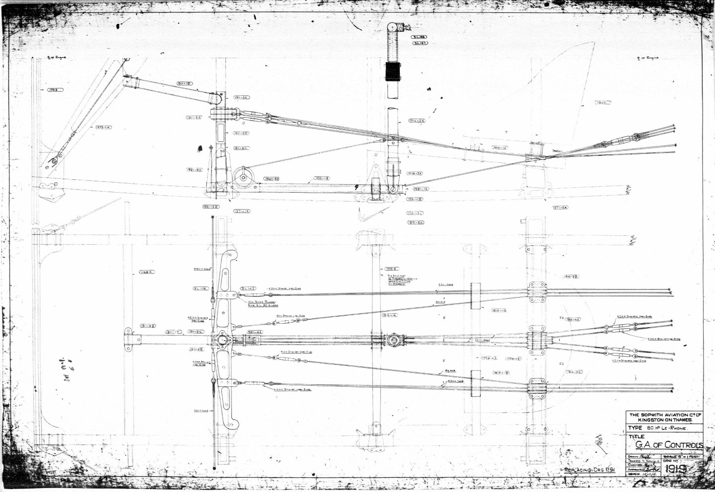
Probably a bit late but this is the general arrangement drawing of the controls of a Pup which would be very similar to that of a Camel.
-
G'day Peter, I found this description on another site, The goal of hull fairing is to bevel the edges of the bulkheads so that the hull planks lay flat. If we didn’t do this, the planks would only hit the corners of the bulkheads. The problem is it only tells a part of the story. The aim of fairing is to have a finished hull with nice flowing lines, without lumps bumps hollows or kinks. Simply bevelling the frames without considering this only allows a greater gluing area, which although important, is only part of the story as I said. Your plank (or batten) should sit naturally against the intermediate frames if held down a few frames apart. Looking at your second pic you would probably have needed to sand the areas indicated below. But only enough to allow the plank to fit.
- 51 replies
-
- 2
-
-
- bounty jolly boat
- Artesania Latina
- (and 2 more)
-
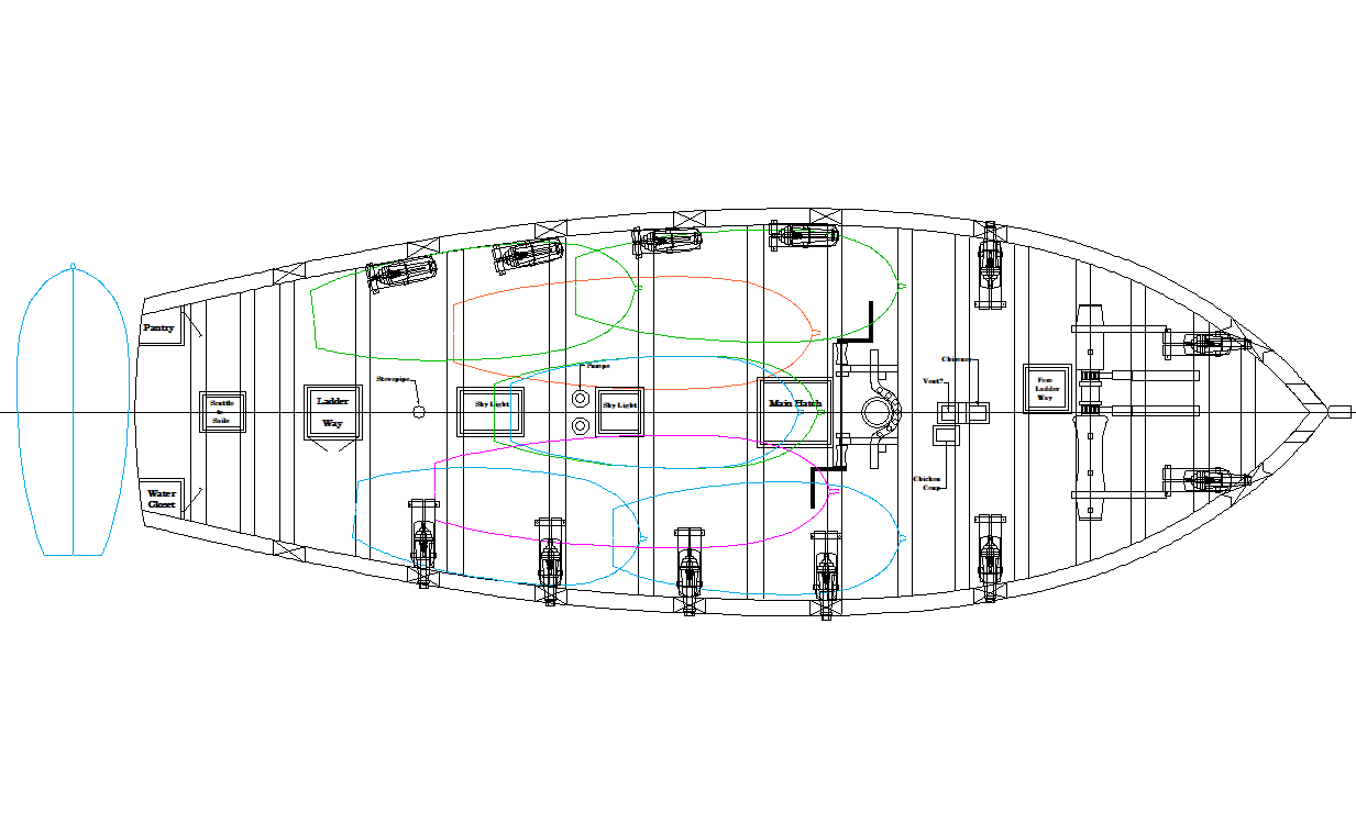
Yeah, that's a one man boat, two at a pinch. Below is Lapwing/Speedy, close enough to Cheerful. The blue outlines are 16' cutters the green 18', the orange a 20' Gig and the pink a 22' Gig, more or less. At a pinch (and in utter desperation) I think a 16' cutter could carry 10 passengers and 2 oarsmen, in a dead calm for a short distance, or more realistically 6 passengers and 2 oarsmen (or 4 and 4) and is I think the biggest I'd put on stern davits. For an 18'er, maybe 4 more (10) but you'd need 4 oarsmen (so 10 minus 2) so only a slight gain, a 20' Gig another 4 more (14) and still 4 oars, a 22' Gig another 4 more (18) but 6 oarsmen (so 18 minus 2). All this assumes a minimum of oarsmen to allow more space for passengers and is just a guess.
- 11 replies
-
- 3
-
-
- cutter
- ships boats
- (and 1 more)
-
Sure does. I'm far from being familiar with UK timbers but I'd look at Ash. You want something that looks like a de-barked tree (in miniature).
-
Thankyou both, that looks like it's going to be an interesting read. In just the first paragraph of chapter 1 we have for the stem "determine the shape of the stem; and find the centre (E), that shall sweep the lower part, at pleasure". So no rule there. And "And draw the line CF for the aft part of the stern-post, to what rake you please" So no rule there either. I believe this is plate 1.
-
Paviljoensjacht 1733 | Blender
iMustBeCrazy replied to Robska's topic in CAD and 3D Modelling/Drafting Plans with Software
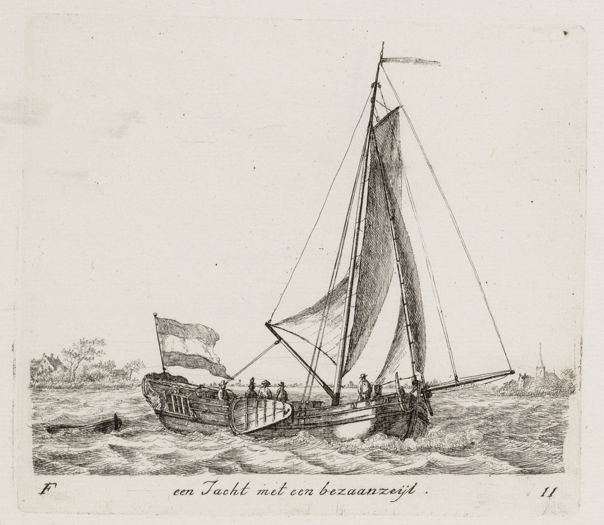
This might help, ca 1791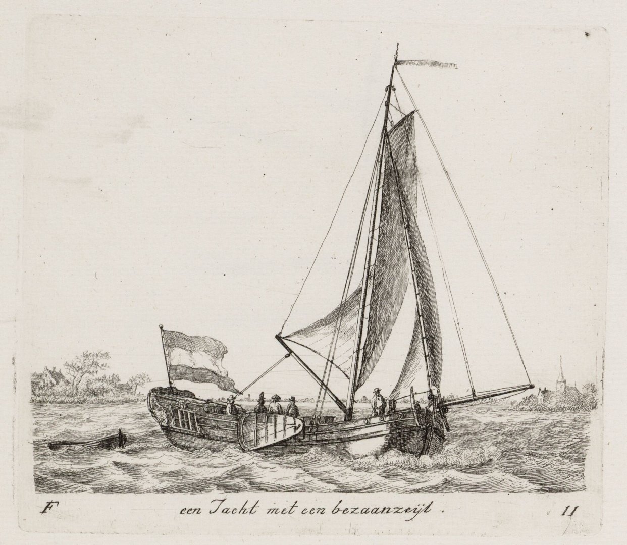
-
A quick look through the photos shows oil lamps in most cabins, sometimes candles, and in the galley. Electric lights in the met station, carbide main lights in the "Ritz" with perhaps a portable electric light as well.
-
And in one of those quirks, in 1938 HMS Bramble (Vigilant class 1822) (by then serving as a lightship) lets say an Aunt of Speedy was modified into a replica of HMAT Supply. Wiki.
- 9 replies
-
- 1
-
-
- Artesania Latina
- First Fleet
- (and 1 more)
-
No I can't. ZAZ7239 is certainly not typical but some variation is common. On ZAZ7349 (yours) I wouldn't be surprised if the station spacing was 1' 2 1/4" around the midship area and 1' 2 1/2" at the bow and stern, but total apparent randomness 😲 But with ZAZ7239 as none of the lines is where the numbers say they should be, I suspect the draftsman put the numbers on a rough sketch as a less confusing reference prior to doing the real drawing. That might suggest that the table of offsets was calculated first but might have been 'corrected' as the drawing proceeded. At this stage I'm just guessing.
-
Yes, the drawing is just a pretty picture ( the shipwright would have built from the table of offsets which I haven't seen for a boat). On the drawing inaccurate setting of a compass would be very easy leading to incorrect arcs, a ruler not quite square, a pencil not sharp enough, heck, a cheap ruler v an expensive ruler. All these and more would lead to errors in the drawing. Yes, there must have been rules (or perhaps more like guidelines ). For masts we have formulae such as "Main-mast twice and a 1/4 the breadth of the boat" etc, there must have been others for, say, the thickness of timbers or the breadth of thwarts or .....
-
You might like to look at ZAZ7239, it gives some insight including dimensions down to the quarter inch and varying gaps between stations.
-
Thankyou.
-
No problem. The model shipways kit was my first build, it was a good introduction but isn't quite the bounty launch. Cornwall's Maritime Museum replica is also close but not quite (there are more photos on their facebook page, there's a link in the Bounty Boats Facts (below)). All kits (hell, all builds) have compromises be they base on cost or skill level. Anyway, have a read of the Launch, 16' cutter and facts threads linked below.
-
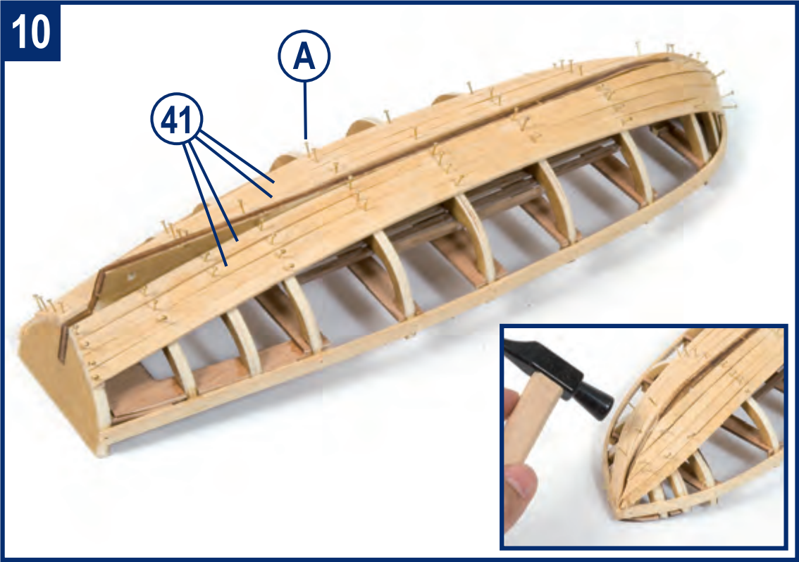
Alfredo, I'm sorry I missed your previous post, I might have saved you some trouble. On a Launch the garboard plank does not follow the keel at the stern, it goes down to the transom instead. Occre does show this in step 10. Occre later cover the 'deadwood' in planking.
- 19 replies
-
- 1
-

-
- Bounty Boat
- OcCre
- (and 2 more)
-
No clear answer here either. Where they may have been carried is a little easier, on deck along the rail (either side) or over the main hatch or dangling from stern davits or dangling over the side or towed astern. ZAZ6347 shows vague outlines of two boats on Vigilant (1821). THIS painting shows at least one boat on Vigilants deck. And THIS painting shows Vigilant with a boat dangling over the side. Missed one, 1783: Cutters employed against smugglers to have 20ft boat instead of 18ft boat for the duration of the peace. Given 200 Ton cutters should have a 22ft gig on a 75ft deck I would expect that Cheerful with a 63ft deck may have had an 18ft boat if they were lucky. Todd, I suggest you cut out some paper boat outlines and see what fits.
- 11 replies
-
- 4
-
-
- cutter
- ships boats
- (and 1 more)
-
No, and I doubt my grandfather used it more that once. Town wasn't that far away and he had a model T truck. When the farm track was flooded he tied ropes to the corners and had the kids try to keep him out of the ruts Life was different then.
-
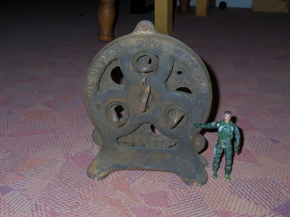
If I have to... Your little toy seems to do a nice job but perhaps you need something more man sized like my grandfathers rope maker. The little guy in the pic will eventually become a crew member for my Bounty launch.
-
Well,it sounds like it hasn't affected your brain anyway. 😁 Likewise.
-
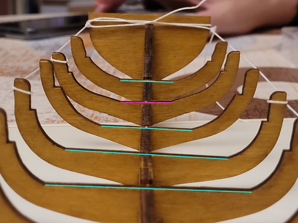
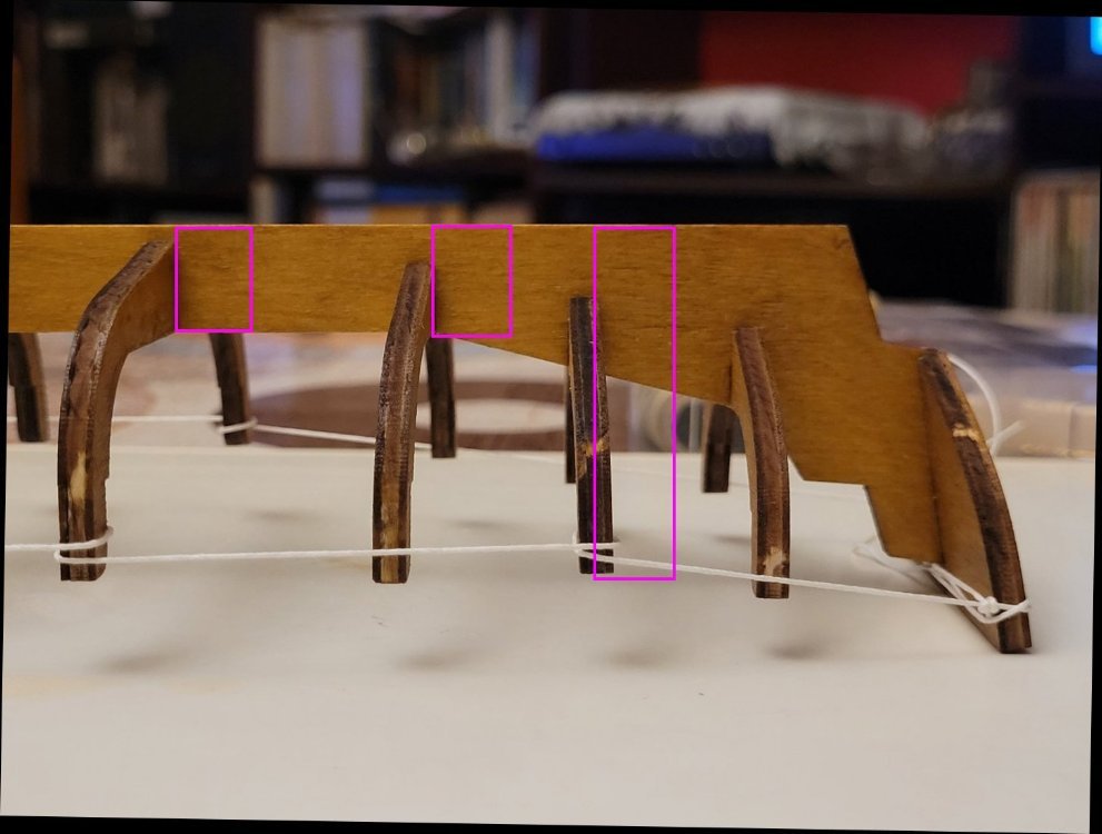
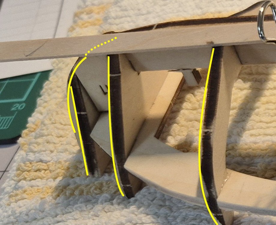
Sorry, it's just a simple way of showing if the frames are square to the keel. Using this method, because of the distortion caused by the camera lens, 8 and 9 can only be checked where they meet the keel whereas 10 is close enough to being square to the camera to be checked for it's full height. The second photo is more obvious, the green lines all slope down from left to right but the purple line slopes down from right to left, clearly different. The distortion is why we can't be certain what is and isn't square from your photos, we can give opinions but you will have to check yourself. If you don't have a carpenters square to check with (or yours is too big), these days lots of paper has very square corners. Photocopy paper, business cards, appointment reminders from your doctor or dentist etc. Probably even birthday or greeting cards.
-
From the photos it looks like part Nos 2 and 10 are not square fore and aft and 10 is also not square port/starboard. The rest I can't tell from the photos, you will have to check them. The keel needs to be fixed, 10 needs to be fixed, 2 should be fixed. All frames appear to be in the right positions. Fairing should fix any minor out of square issues.