woodartist
-
Posts
292 -
Joined
-
Last visited
Content Type
Profiles
Forums
Gallery
Events
Everything posted by woodartist
-
Thanks for the suggestions!! I really like how it is progressing now with the bulkhead and keel being in sync with the patterns. It is an amazing difference in how well things fit together. I wish I had done this earlier, and saved myself some of the frustration. I have all the bulkheads in place and the bow and stern filler blocks in place. I never thought about putting filler blocks in all the bulk heads. That would sure simplify things. I will put together the size of pieces I need for the filler blocks ad see if i need to get some more wood. I have a lot of leftover basswood from my bird carving tht may just be enough. I will watch your progress and look forward to your commentary on the right dimensions for positioning the sills.
-
As a novice reading thru your build log was like a graduate level course in boat modeling. Thanks so much for sharing.
-
Der Alte Rentner was absolutely correct, I was not successful in replacing bulkhead A. So, I threw the whole thing in the garbage and started over. This time I cut out my ow bulkheads from 1/4" birch plywood which is actually 3/16" and the keel from 1/4" cherry. They turned out well, and accurate, and will proceed to repeat the prior process but hopefully without the mistakes made in round one.
-
I have not been happy at all with the quality of my workmanship and the endless issues I was having with the bowsprint. I have rebuilt it two times and it is still not fitting the way it should. This became even more obvious when I was installing the waterway and planksheer. So I am going to redo it again including replacing bulkhead A. I will not let this deter me!! Next post will be a few days but it will have something that looks like it should.
-
This looks really good! I am glad you are ahead of me on this build. I almost completed the waterways today will start the planksheers tomorrow. I keep reading your log to make sure i have not missed anything. Keep up tyhe freat work, I am always looking in on your progress.
-
i read your build log religiously and never start the next section until I have read your log. I do not have a computer in my shop so I print pictures from your log almost daily. Thanks for putting in the time and effort to do the log!!
-
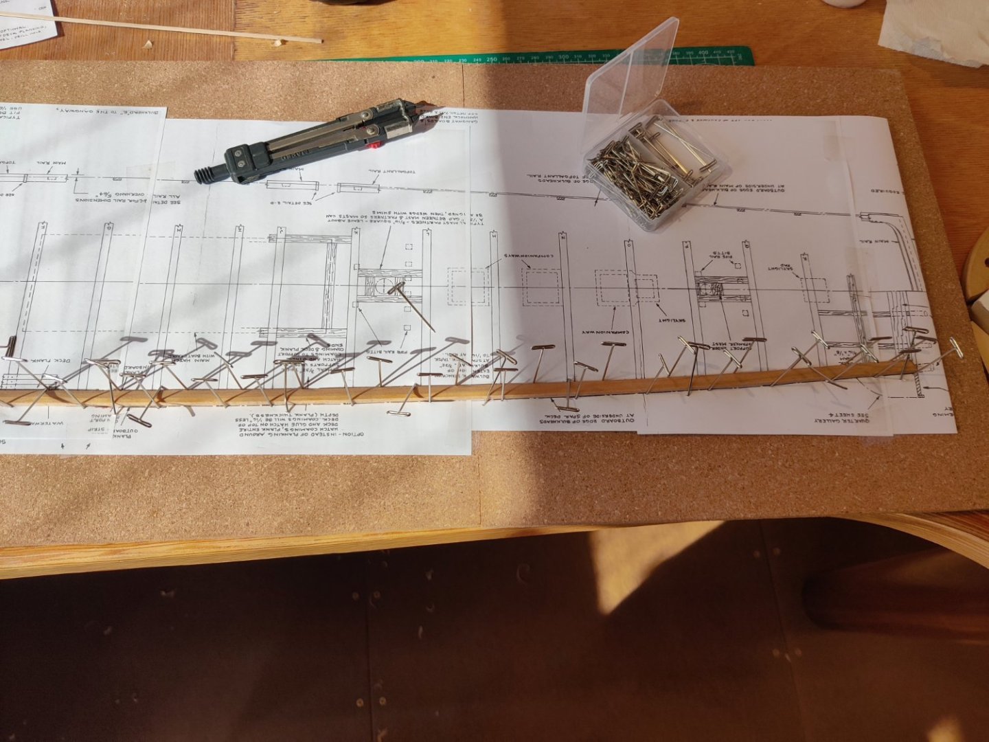
Working on the waterways, finished inside bevel for port side, waiting for more wood to arrive before I can do starboard side or planksheers. I still need to bevel backside of waterway before I can install. Soaked wood for 2 hours then set in the jig of push pins in cork board.
-
When you were installing your waterways, after you had beveled the inside edge to meet the planking, did you have to clamp in the waterway as you cut the bevel for the side that backed up to the bulkhead? Did you do any wetting of the waterway before you forced it next to the bulkhead?
Thanks for your build log it has been of great assistance on this journey.
- Show previous comments 1 more
-
-

I did something similar. I traced the curves onto a piece of scrap plywood. Then where you used pins, I used dowels protruding to a smidge below the height of the waterway. I soaked the waterways about an hour, set them between the dowels, and used a steam iron to set the shape. I saw that technique somewhere at the website but can't remember where.
Like me, you followed Bob Hunt's direction on the waterways. I think they're too flat and the bevel isn't steep enough. If you look at pictured of the waterways on the Constitution, and/or consult the plans, you'll see that they should be a smidge taller and less deep. Not being a stickler for absolute fidelity to the original, I have no problem with keeping them as they are - just pointing it out in case you feel differently.
I noticed you got the sanding tools I mentioned in my log. They're great, aren't they?
Lastly, hard to tell in the photograph above, but did you not bevel the waterway at the stern? I think the angle where it will mate with the section going across the stern should be about 45 degrees. No?
-
-
Here are the photos i referenced in post but failed to include, my bad,


-
Work proceeded on the stern transom structure. In the process i needed to saw some non standard angled pieces. I was having issues holding them in place and sawing at the same time, the metal mitre box did not have slots for the angle needed. Then I discovered that if you turned the mitre box upside down and put it in the vice you could freehand a saw cut and hold the wood against the back wall of the upside mitre box. As many others have documented in their build logs the two outside stern supports were difficult to align. i placed a 5/16" wedge between the backside edge and the adjacent support and that seemed to work to finish the alignment. There was a lot of discussion about the bevel on the front edge of all 6 supports and the bottom of the two outside supports. There is definitely a bevel but be careful it is very easy to over do it. i did over do it on the first one and was more gentle on the rest.
-
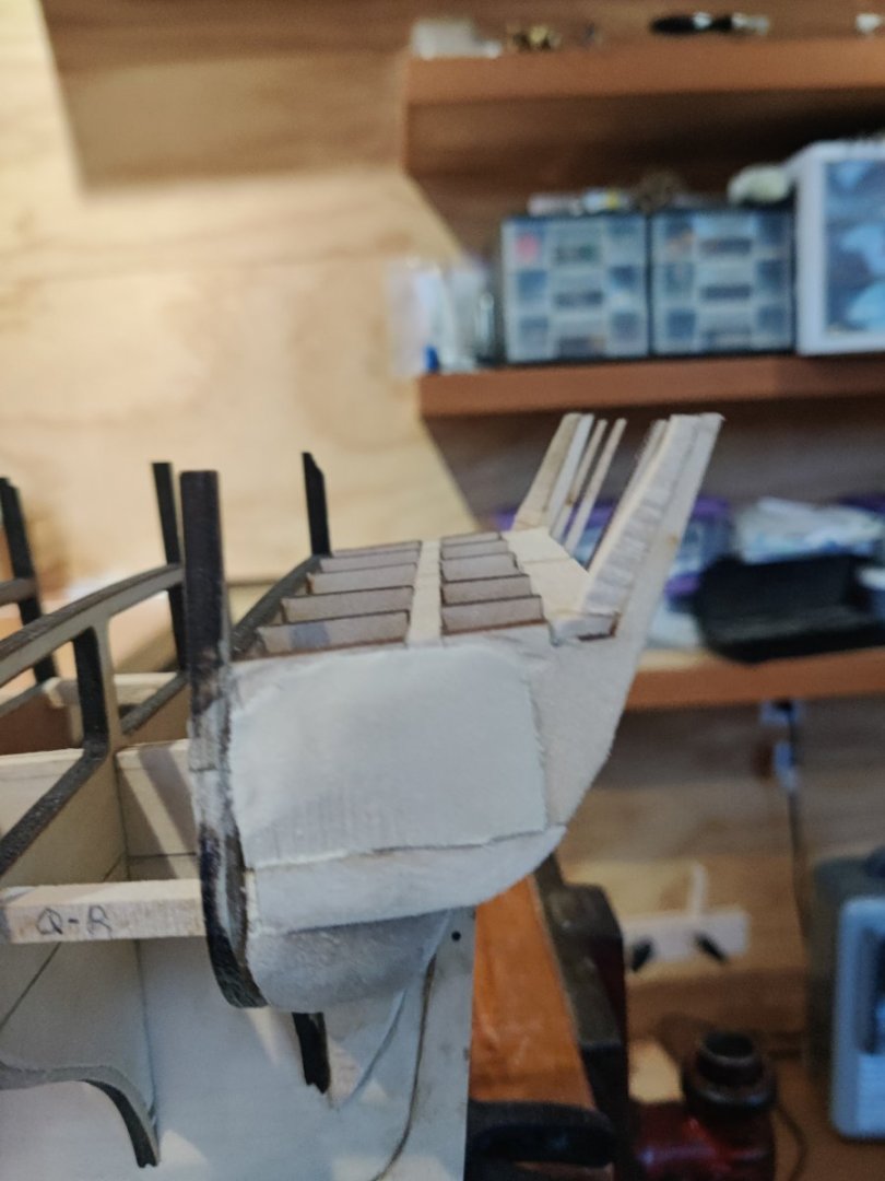
well Der Alte Rentner was totally correct! I was not successful in cutting the notches in place. I ended up removing the bow filler and had to make new ones. Thankfully, I had used weldbond to glue the bow filler in so I was able to use alcohol and get them to release.Secondly, the spar deck framing pieces broke while trying to install them. I discovered that my notches were not accurate enough and I had to find a better way to cut the notches. I had a set of micro chisels from Veritas and had seldom used them but the 1/8" Veritas chisel was perfect for the job and a lot more accurate than the xacto blades. I cut the new notches in the bow filler with the chisel as well. I tried multiple ways to get all the pieces assembled and was having no success and getting very frustrated. I went back to member build logs to see if any of them had advice. Sure enough once gain JSGerson had the same problem and decided to first install the spar deck framing piece and the insert the other 5 pattern timbers. He said he had to "fudge" to get them in place. I appreciated his honesty because that was the only way I got them installed as well. Upon completion I checked the measurements with the plans and Hunt's practicum and they were correct. I have also installed the strengthening timbers. If you notice a difference in colors for the wood I used some cherry for timber #4. I have not yet sanded the bow structure, waiting for it to dry. Next onto the transom.
-
Thanks, I checked mine and I have the same issue. I will correct it now.
-
Did you correct bulkhead A and C before you glued in the bulkhead?
-
I like your solution better than Bob Hunts, the fewer seams the better, less chance of error. The thickness of the stems varies a lot, I have not figured out a way to make them uniform yet without using shims. The other part of that problem is the only way to know the correct distances between the stems is to transfer a measurement from the plans.
-
I think it is a good idea not to make the notches. Once the other framework is in place it will certainly be strong enough. I put the filler in with Weldbond so i can undo the pieces without too much trouble. I think I will try that first.
-
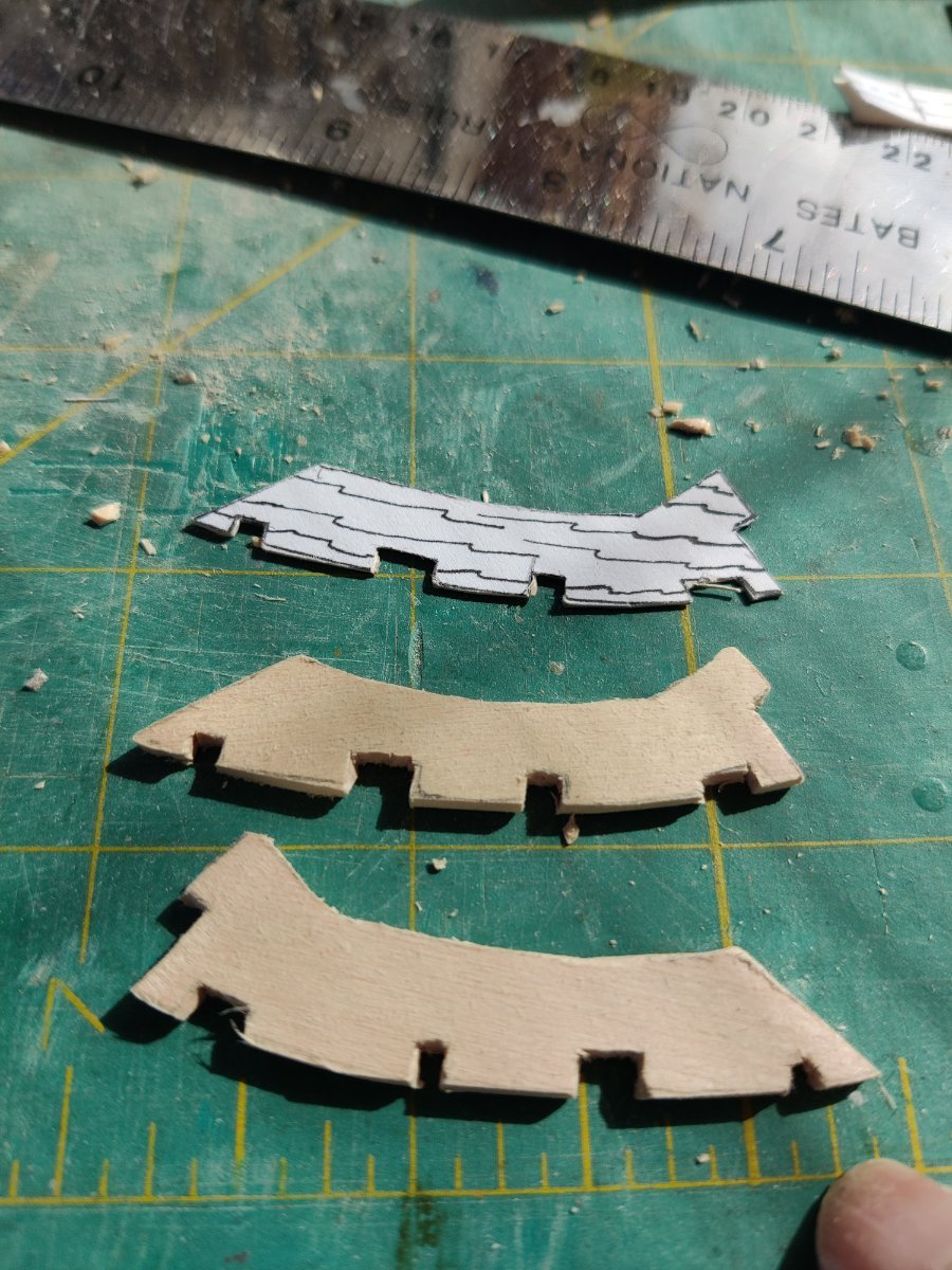
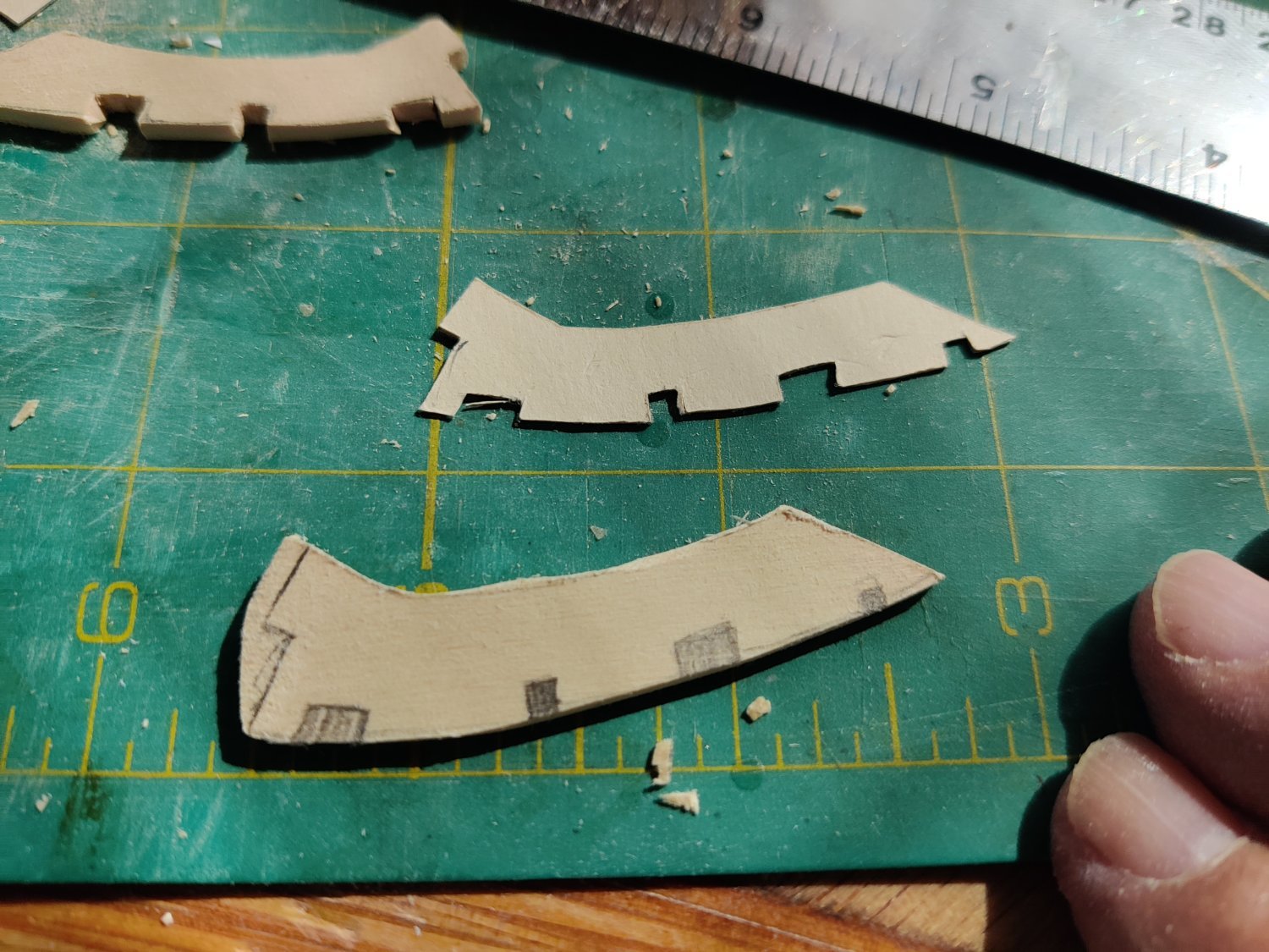
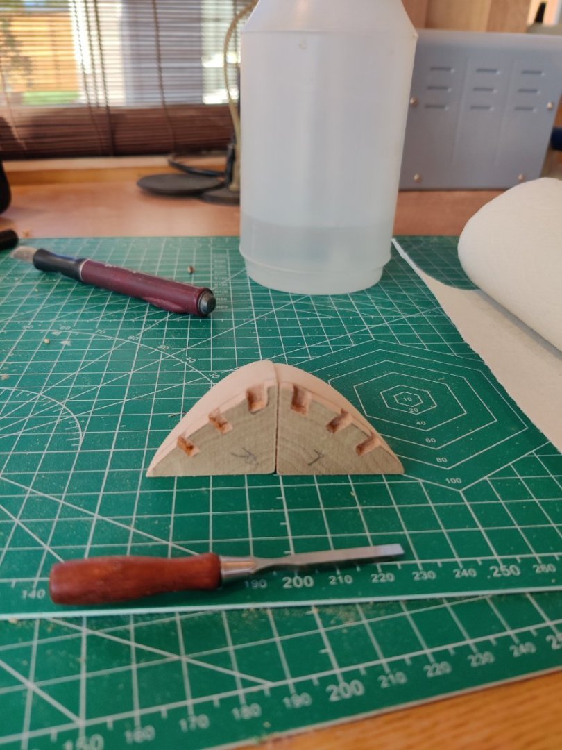
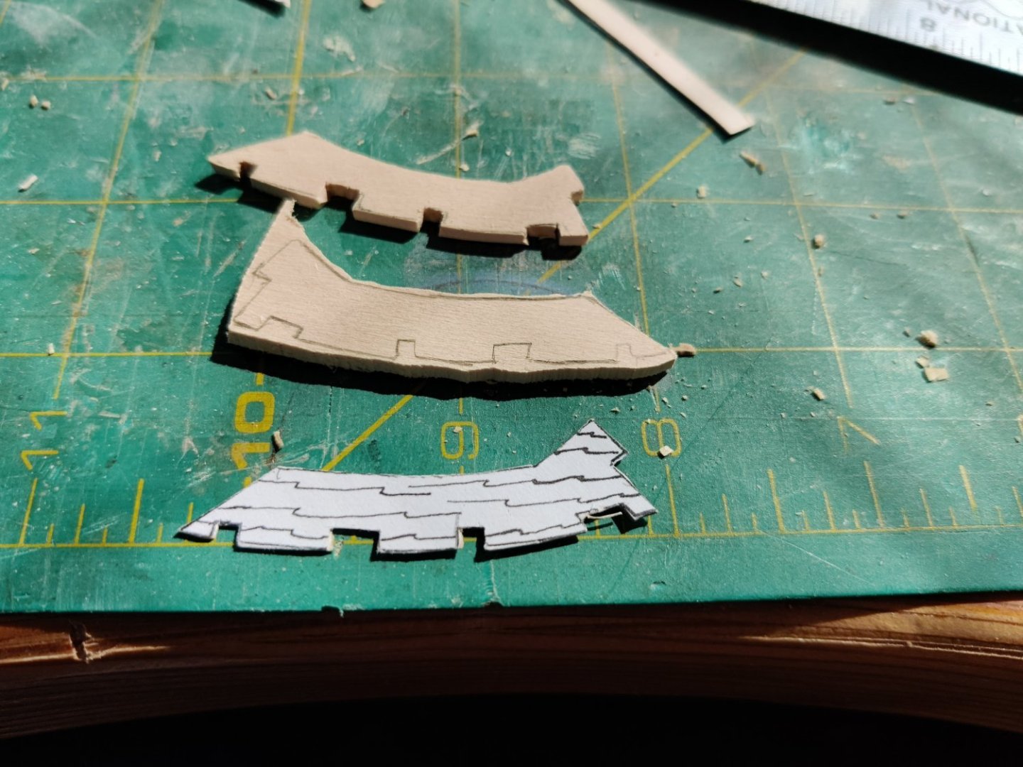
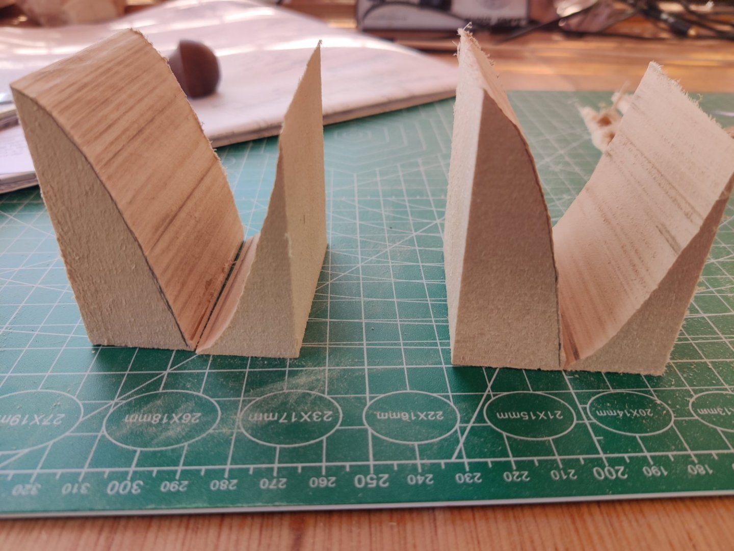
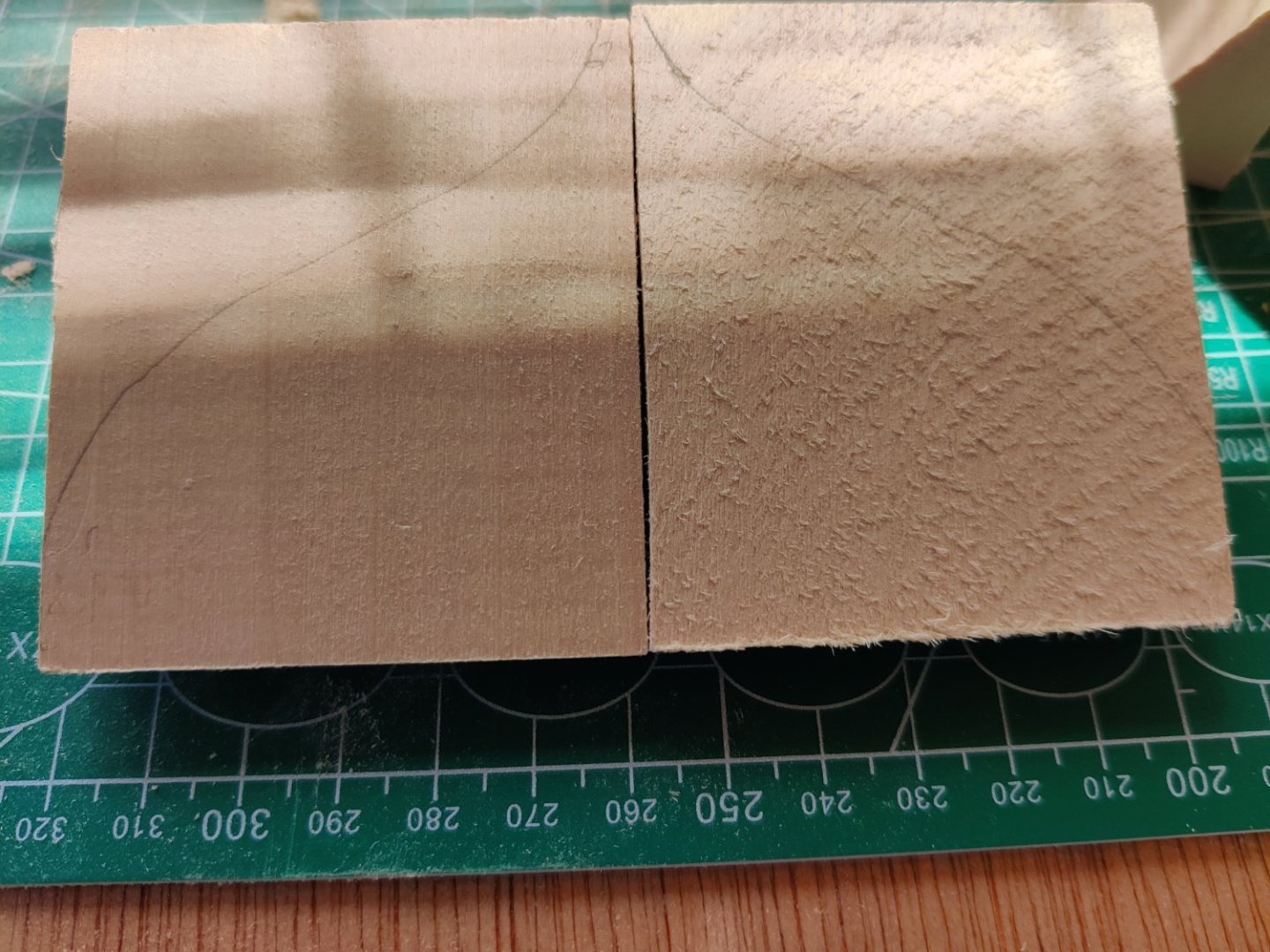
Now I have started work on the bow framework. After I cut out the pattern and found the 3/32" X 2" X 24" piece of wood in the kit, I cut out 2 pieces from the wood strip with a jewler's saw. You can see how close I could saw the piece to the lines, Then I sanded it down to the lines and cut out the notches with a Xacto blade. I used a thin blade and after marking the perimeter to be cut I cut tiny slits, the cut sideways and removed chips, then recut the perimeter and repeated the process.


-
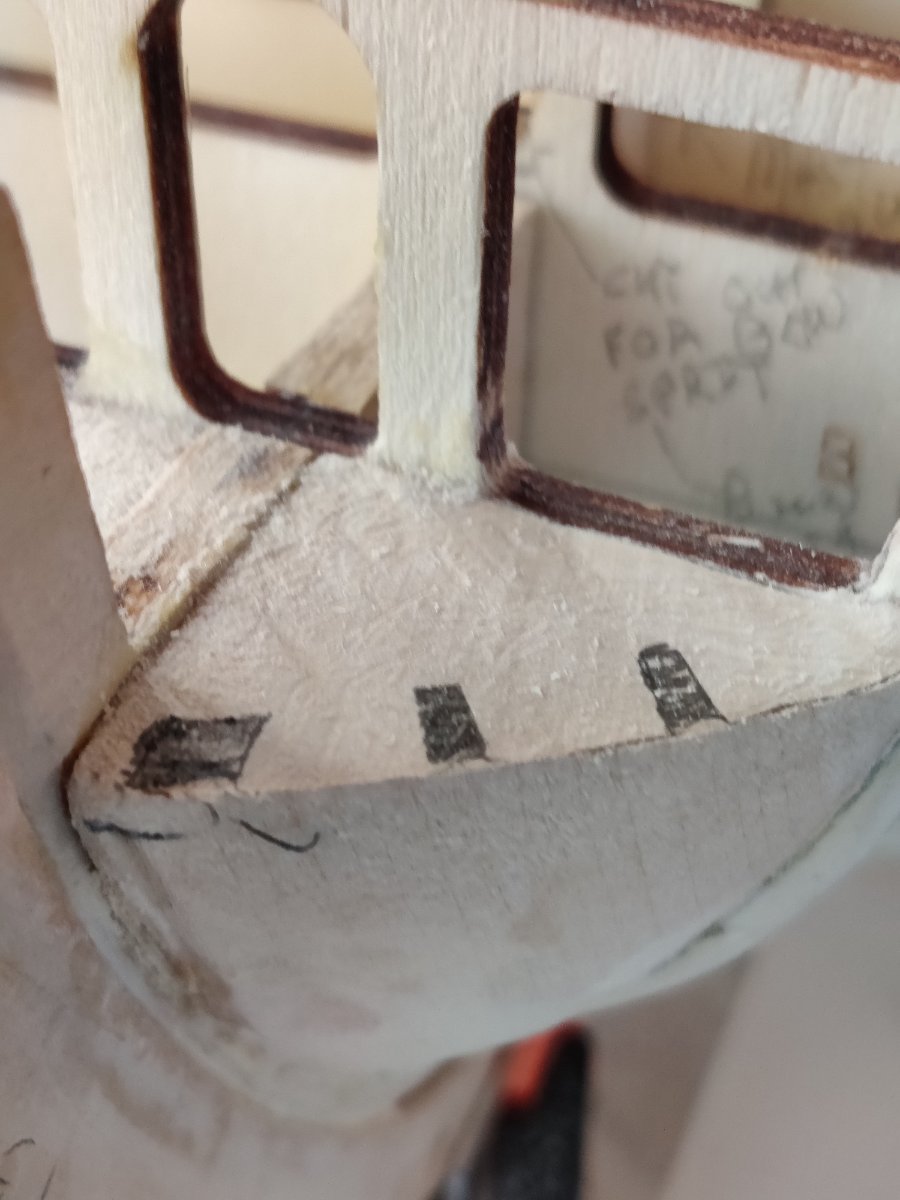
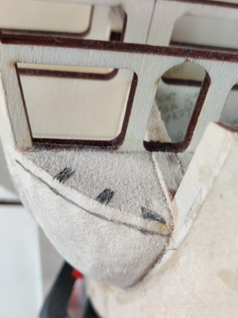
The bow fillers are in and the notches marked for removal. I had to go back to them several times in order to get them reduced enough. I wish I had cut out the pattern for the bow notches earlier because it is a very good guide to ensure you are on the right course. I followed the suggestion by Der Alte Rentner and used a piece of planking to see if it would smoothly fit.
-
Thanks for the advice Der Alte Renter, I followed your advice and double taped the transom and you were correct I had to reshape the stern blocks twice. I hope it is close. I used the template from Bob Hunt's practicum and I Iooked at your build log. Frankly, your build log was more useful.
-
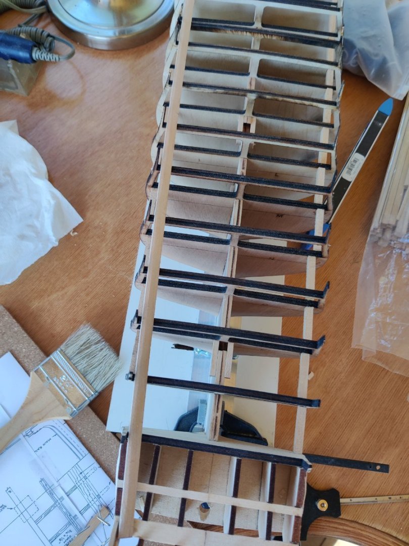
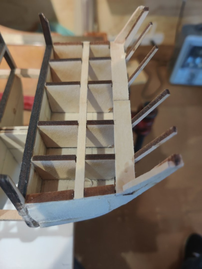
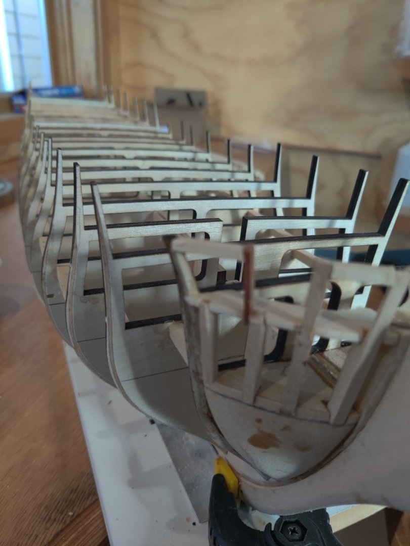
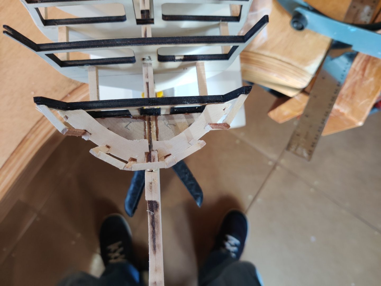
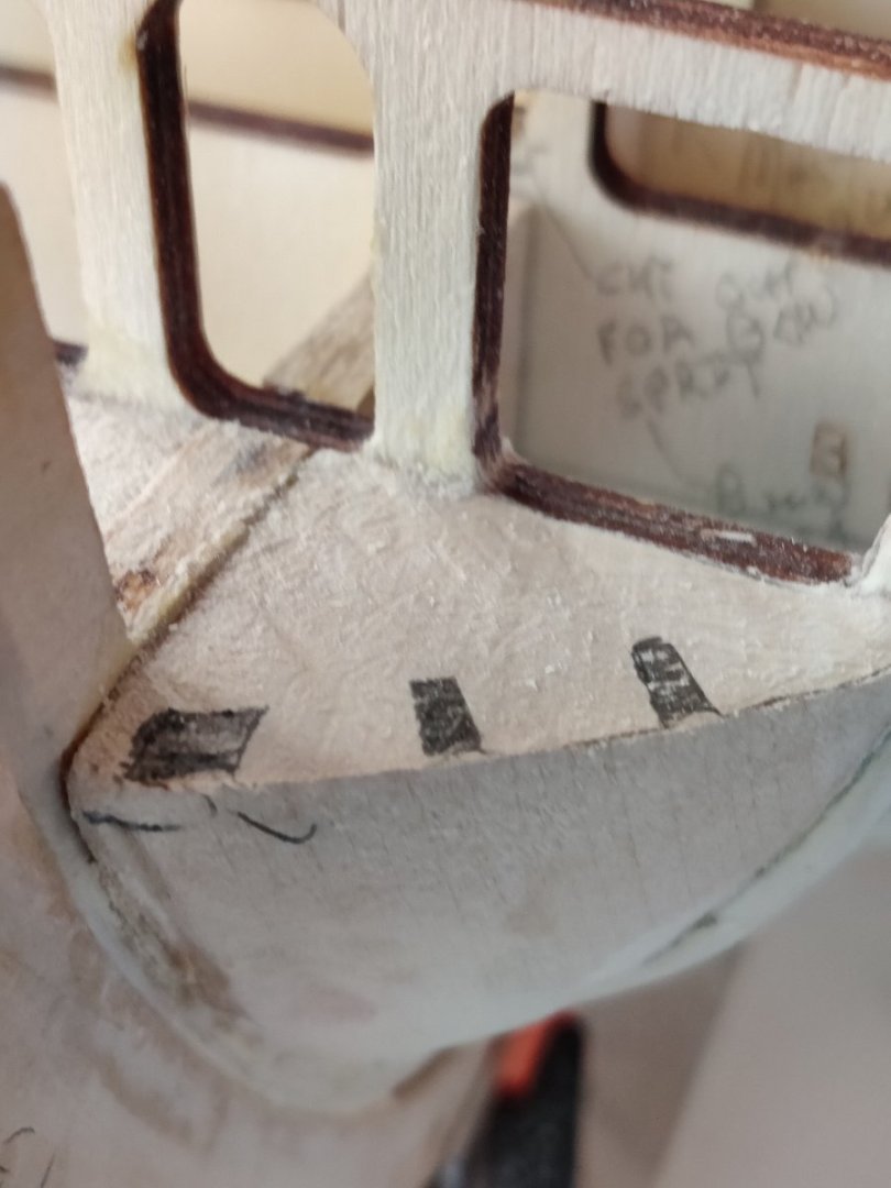
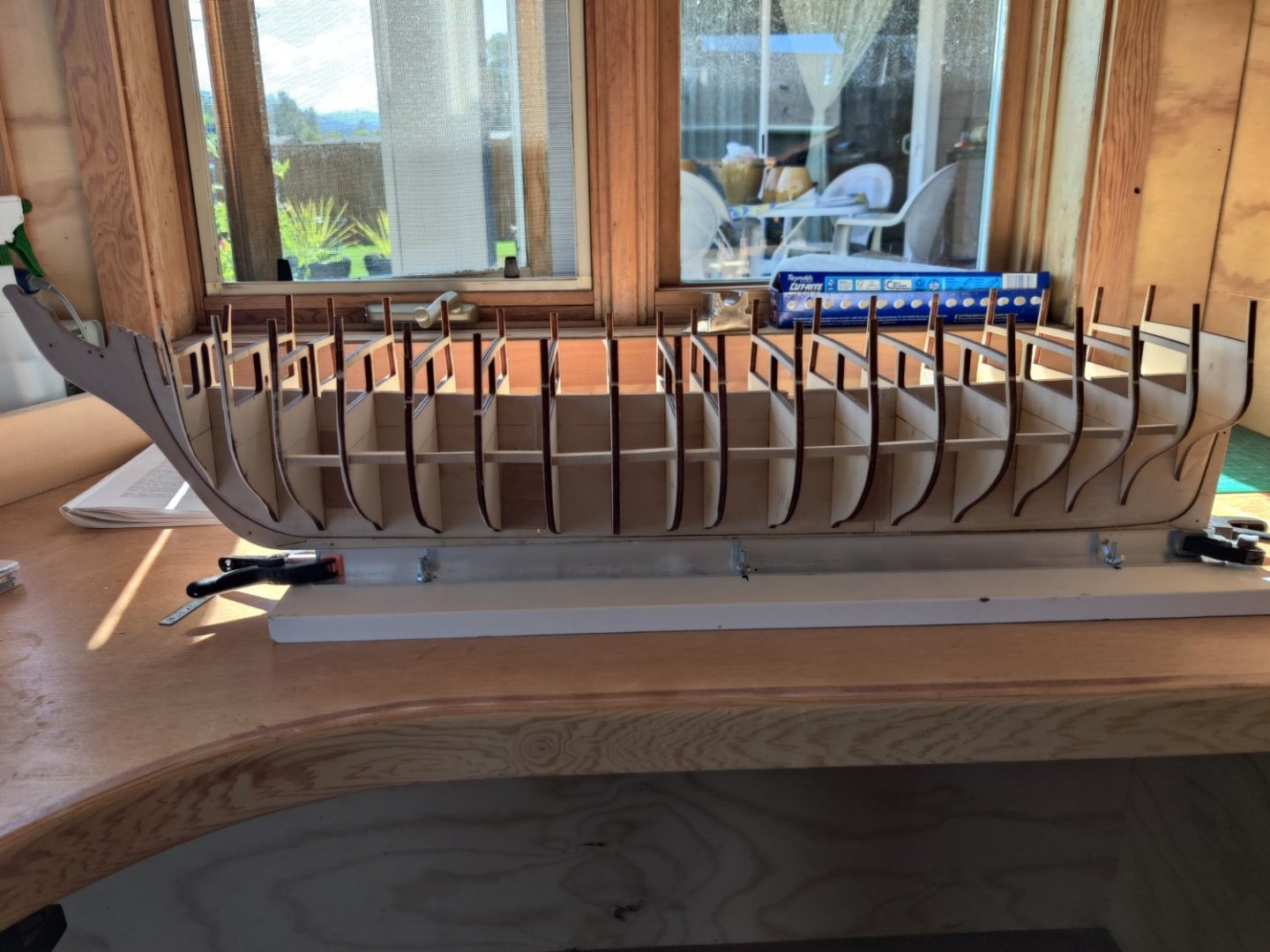
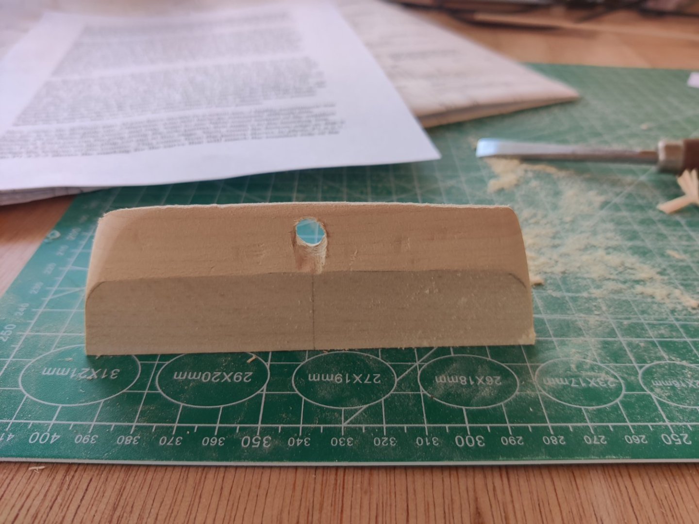
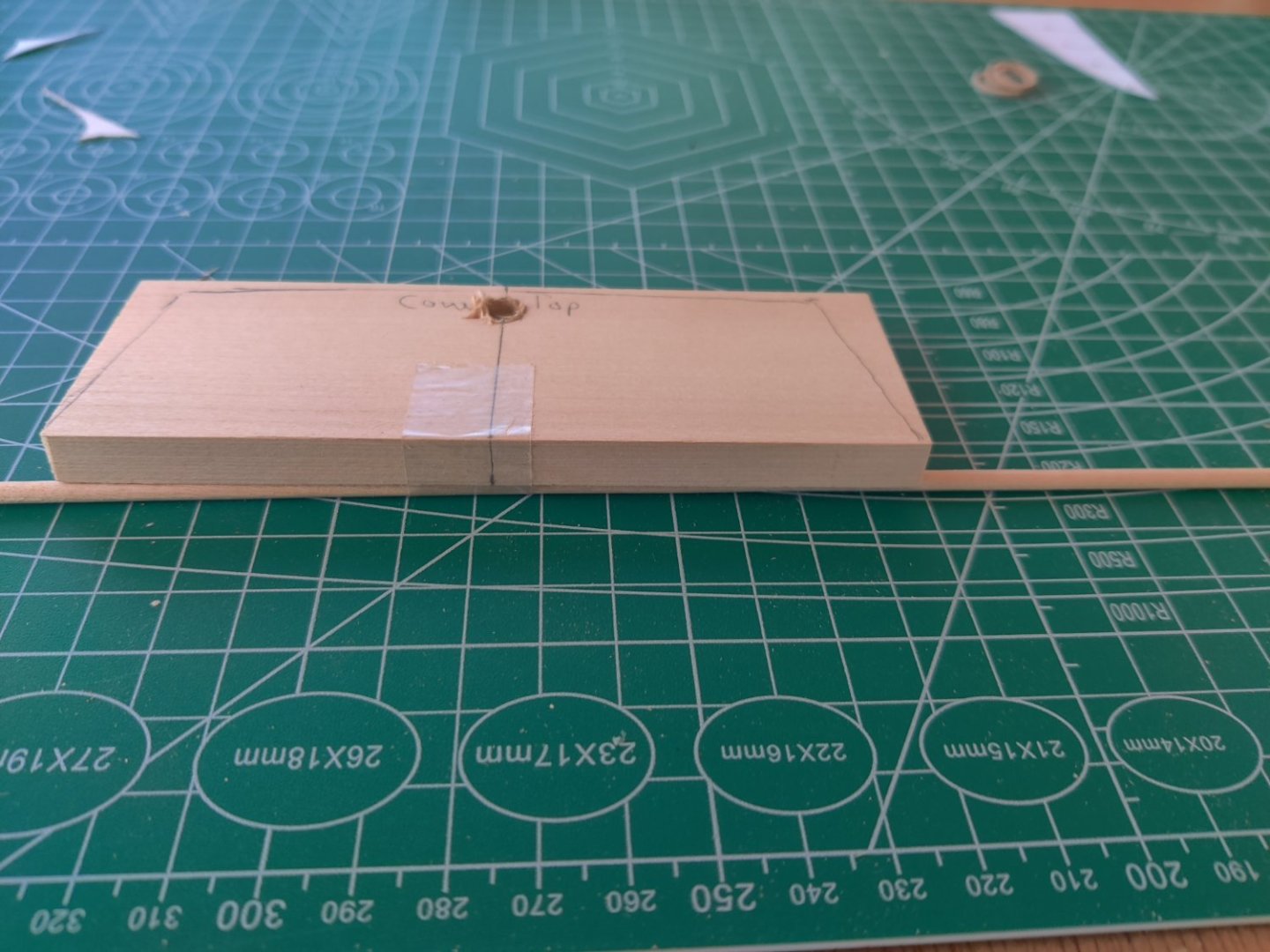
Progress continued over last four days. All the bulkheads have been inserted and glued in, the edges were faired according to the plans, and 3/32x3/32" spacers were inserted. I copied each bulkhead plan, cut it out and transferred the center lines, marked the areas to be faired and trimmed them before inserting the bulkhead. I cut out the transom filler block. Then I placed a 1/8" dowel under the back edge of the transom filler block to grt an angle on the hole. The dowel was too small to get the tight angle so i replaced it with a 5/16" dowel and re-drilled in the rudder hole. I used a power drill and started with a 1/16" bit and then 3/16" bit and then 4/16" bit. I finished it to size with a round wood rasp. I then shaped it with my #1 chisel which is 1/2" wide. Then sanded the corners according to plans. I dry fit it and lined up the center line on the transom filler piece with the center line on the keel and the center line on bulkhead R. I cut out the two filler pieces that fit below the transom filler piece with the bandsaw and then sanded them to the cut line. There were some burn marks from the bandsaw which I sanded out. I clamped the lower filler blocks in place with a small brass bar clamp and marked the edge of the bulkhead on each. I will use 5 minute epoxy on the transom tomorrow and then finish the 2 lower filler blocks.
-
thanks Der Alte Renter so much for responding to my request for help. I will follow your guidance and level the deck area and deal with the fairing issues when time arises. I have inserted 3/32x3/32 spacers between all the ribs as the plans recommend except at each end where the blocks will be inserted. Inserting the blocks is my next item on the to do list.
-
HELP HELP HELP Now I have a problem. I finished putting in all ribs and then learned that on rib section O I did not get the rib aligned with the reference line. It is now 1/16" too high on top and 1/16" too low on bottom. It is solidly glued in. How do i correct it? Do I shim the the lower section and shorten at top? Do I cut out the rib out entirely and cut out a new one from a piece of plywood that is the same thickness? I have a band saw and could try that.
-
I like your solution too.
-
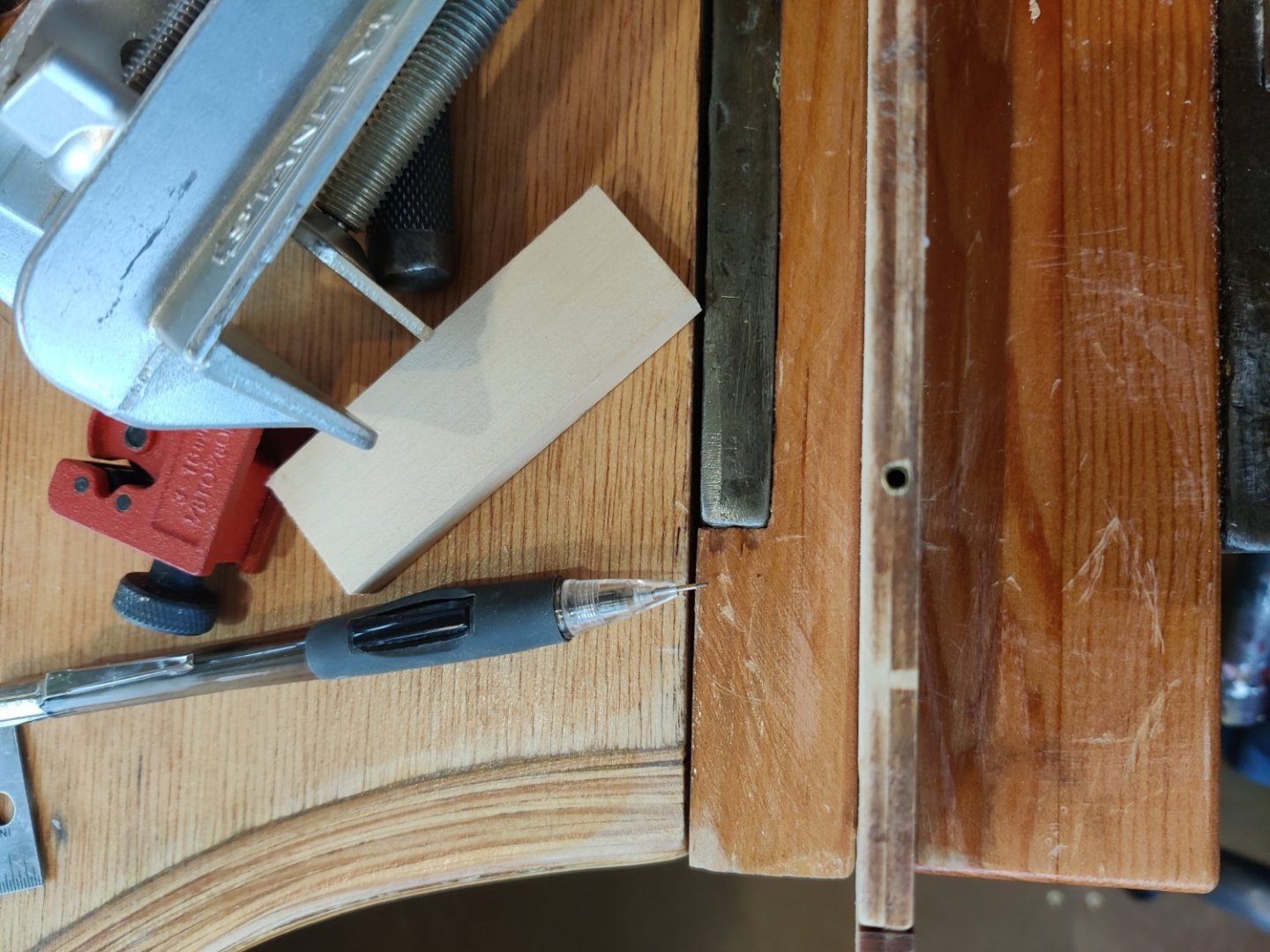
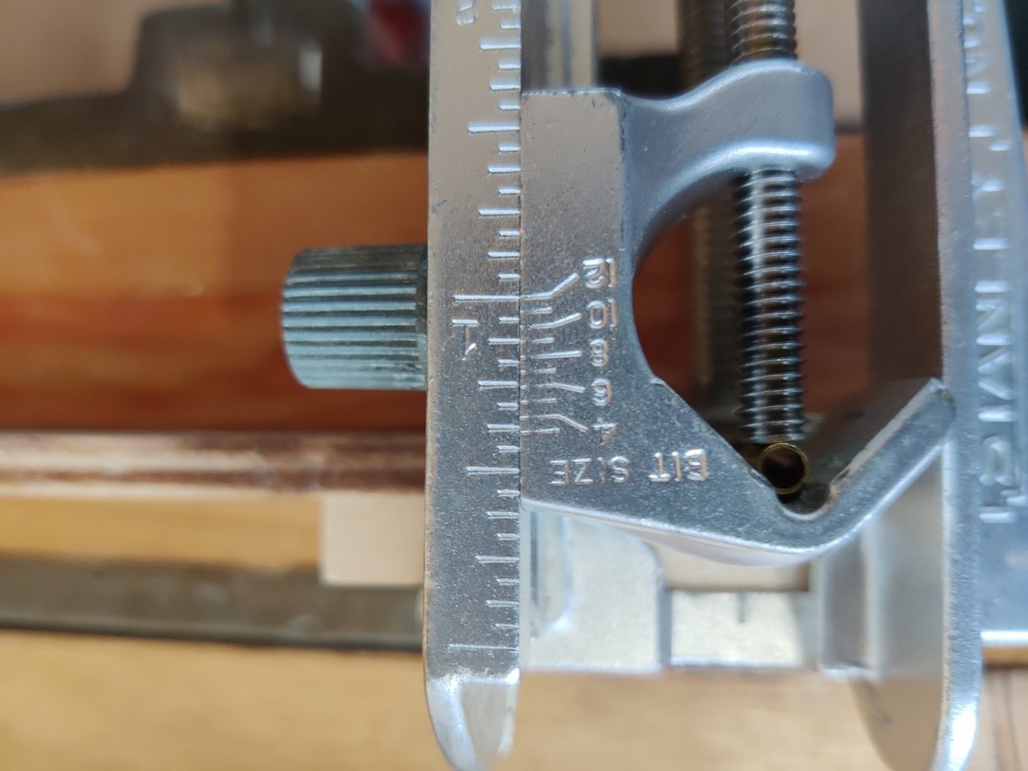
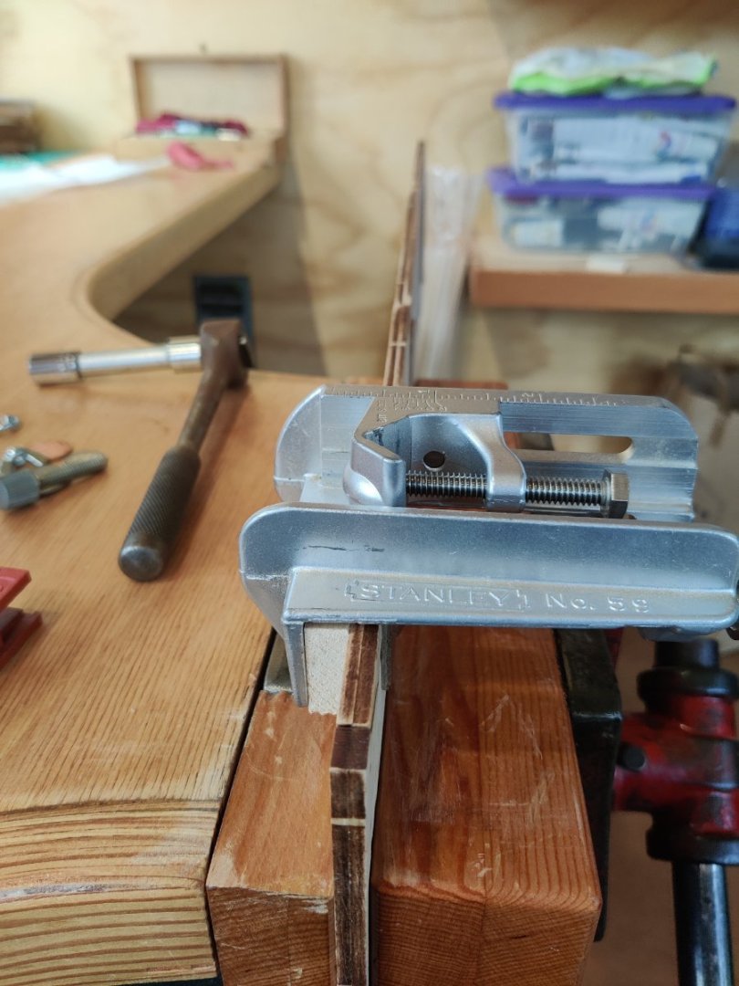
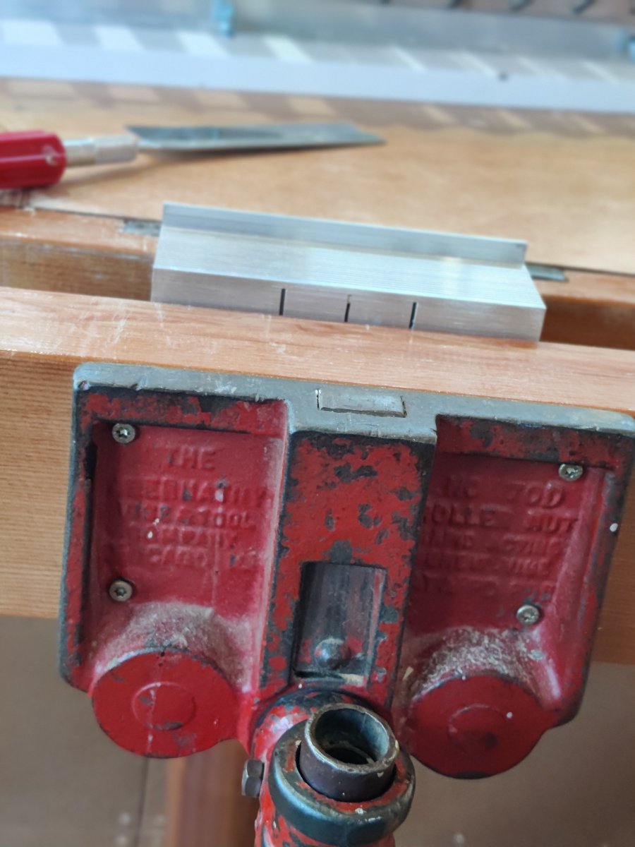
So I tried to use the Stanley dowel jig. Two problems became apparent, one, the jig was designed for a minimum wood thickness of 1/2", the second was that the bolt that held the metal sleeve was two short to accommodate a sleeve less than 1/4". I solved the thickness problem by using a wood scrap as a shim. I got a longer bolt but had to use a socket and socket extension to screw it in. I cut a brass tube with an internal diameter of 1/8", which would be my dowel size, and cut the 1/8" brass tube into 4 one inch sections. when you cut brass tubes with a tube cutter it reduces the internal dimension. So after i cut them I reamed out one end with drill bit so I could use 1" brass tubes on my mounting board that would be inserted into the dowels. So you kill two birds with one stone, you get the reinforcement from the brass dowel and you have a secure way to mount the boat. I put in four brass tubes, three at the joints on the keel, and the fourth one about two inches in from the end of keel piece 5. Now I am ready to start aligning the ribs next. The jig enables you absolutely get a straight hole centered on the keel. and you can set the depth as well. On the first photo you can see the red tube cutter and the shim. On the second Photo you can see the brass tube centered on the keel.