


woodartist
-
Posts
123 -
Joined
-
Last visited
Content Type
Profiles
Forums
Gallery
Events
Posts posted by woodartist
-
-
Thanks, I checked mine and I have the same issue. I will correct it now.
-
On 7/7/2023 at 1:32 PM, Der Alte Rentner said:
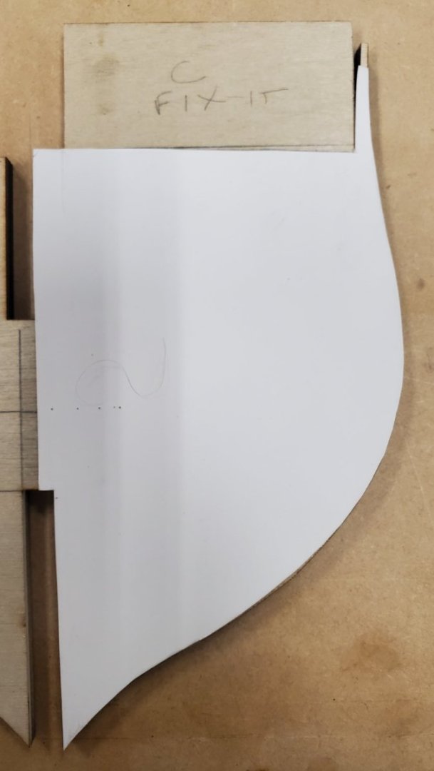
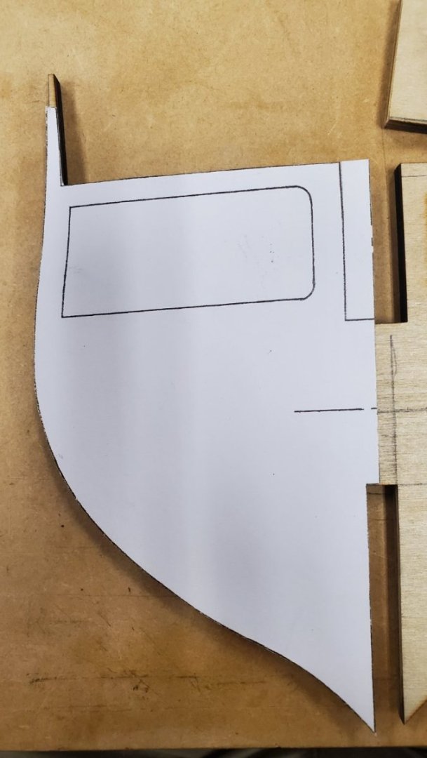
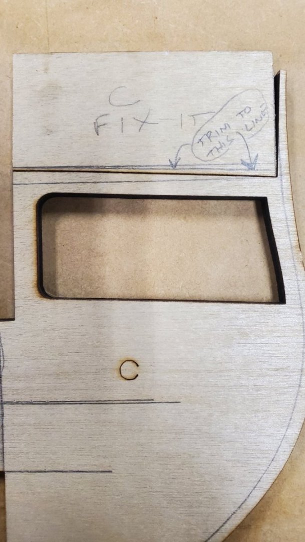
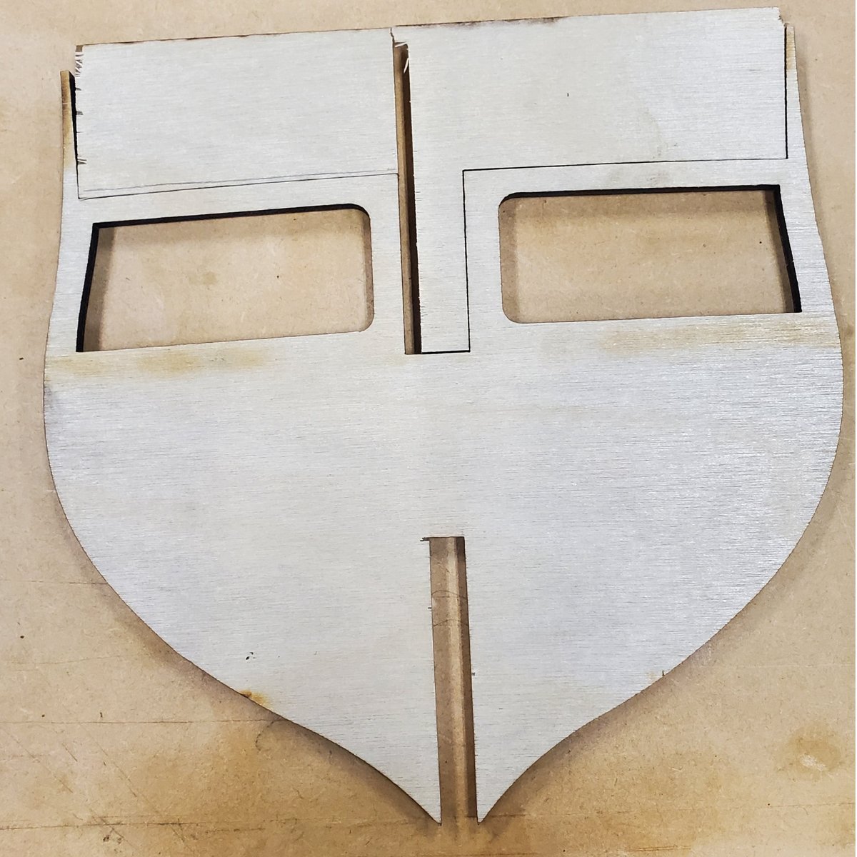
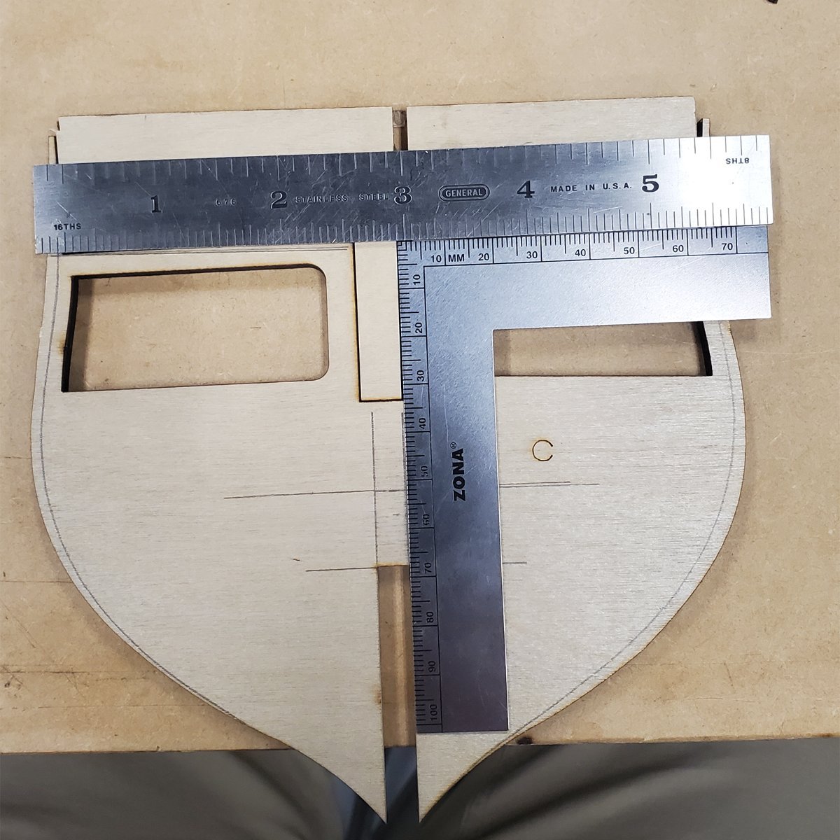
Before I continue with my build, I have a question for any of you who have build Conny from this kit. The next step in the process is to glue the bulkheads onto the keel. I noticed that the some (?) bulkhead components have yet another flaw. See below:
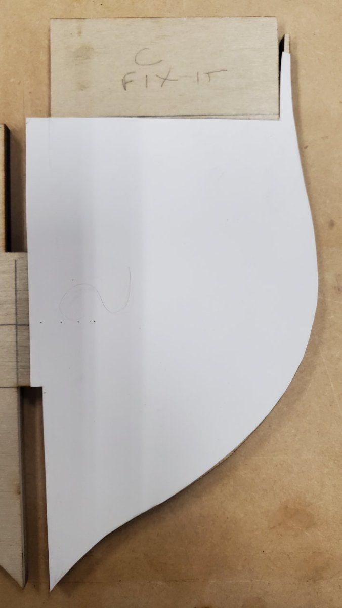
I don't plan to install a gun deck, so the fact that the flaw is repeated in what would be the gundeck (lower) cutout may not be an issue. However, when it'll get to be time to plank the spar deck, absent a fix now, the portside of the deck will be slightly lower than the starboard side. I see two options. One is also illustrated below, and the approach I am taking with bulkhead C. It occurs to me that I could also slightly taper slots in the offending pieces to allow for a little wiggle room to align the bulkhead so the deck edges line up with the closest neighbors. C would align with B and E, and so forth.
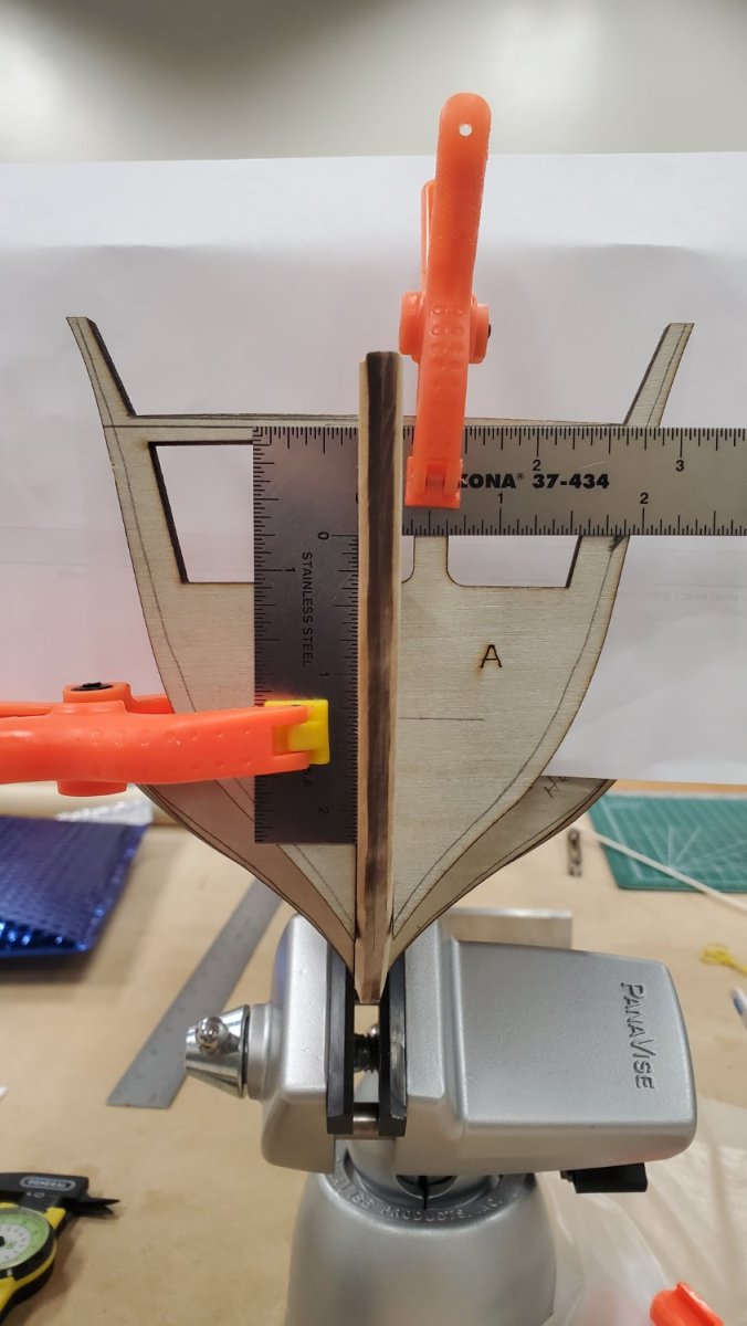
Sorry, the photos are out of sequence. But I think third one (Bulkhead A) clearly illustrates the problem.
(I now see the advantage to making the bulkheads from scratch, but it's probably less work to fix the poorly laser-cut parts than dust off my scroll saw.
 )
)
Thoughts? Advice?


Did you correct bulkhead A and C before you glued in the bulkhead?
-
On 8/7/2023 at 6:30 AM, Der Alte Rentner said:


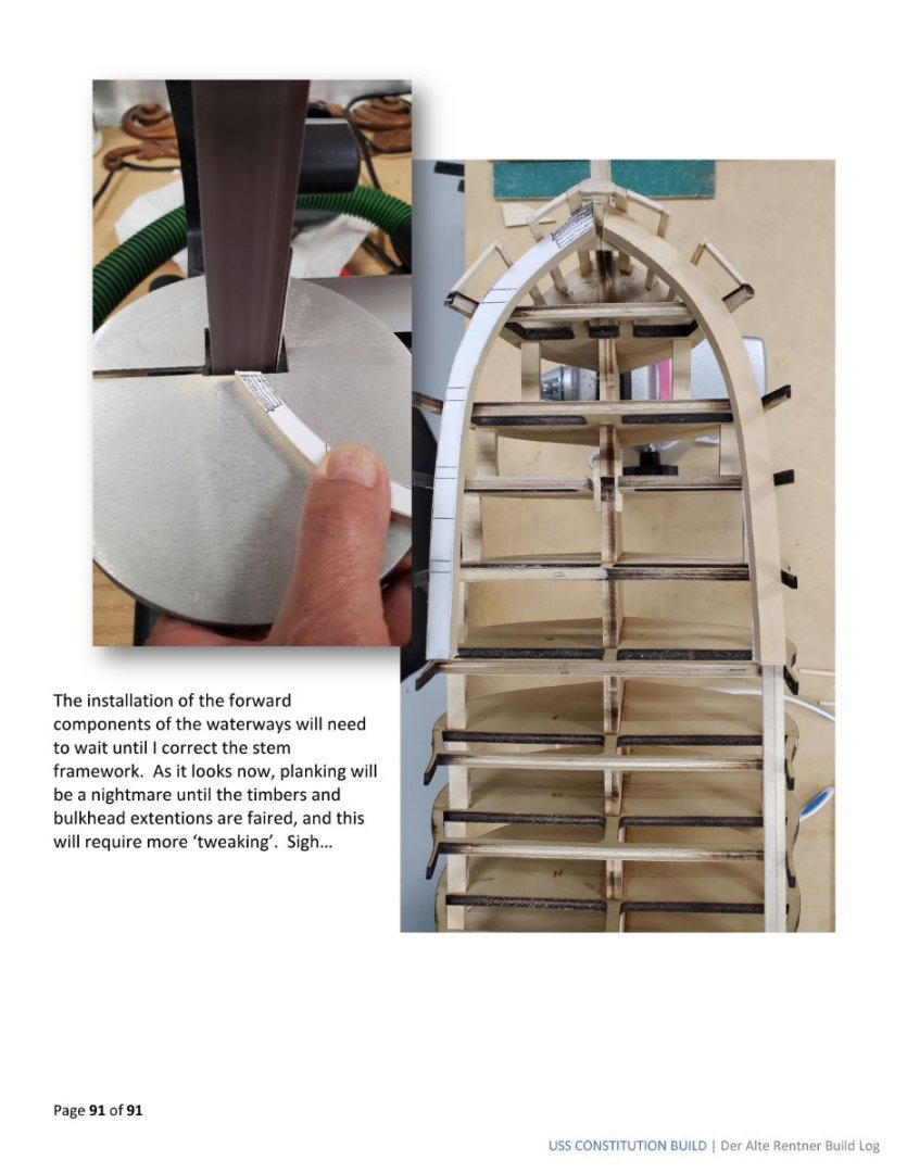
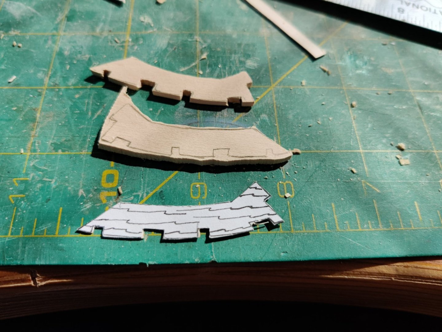
I like your solution better than Bob Hunts, the fewer seams the better, less chance of error. The thickness of the stems varies a lot, I have not figured out a way to make them uniform yet without using shims. The other part of that problem is the only way to know the correct distances between the stems is to transfer a measurement from the plans.
-
I think it is a good idea not to make the notches. Once the other framework is in place it will certainly be strong enough. I put the filler in with Weldbond so i can undo the pieces without too much trouble. I think I will try that first.
-
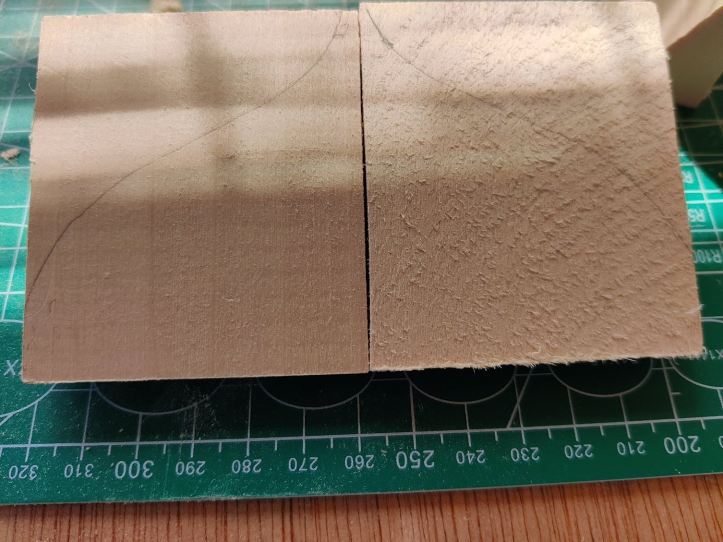
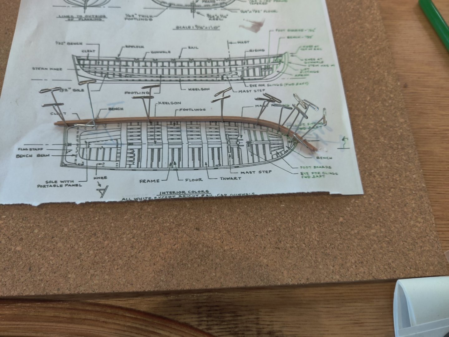
Now I have started work on the bow framework. After I cut out the pattern and found the 3/32" X 2" X 24" piece of wood in the kit, I cut out 2 pieces from the wood strip with a jewler's saw. You can see how close I could saw the piece to the lines, Then I sanded it down to the lines and cut out the notches with a Xacto blade. I used a thin blade and after marking the perimeter to be cut I cut tiny slits, the cut sideways and removed chips, then recut the perimeter and repeated the process.


-
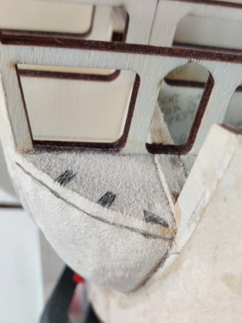
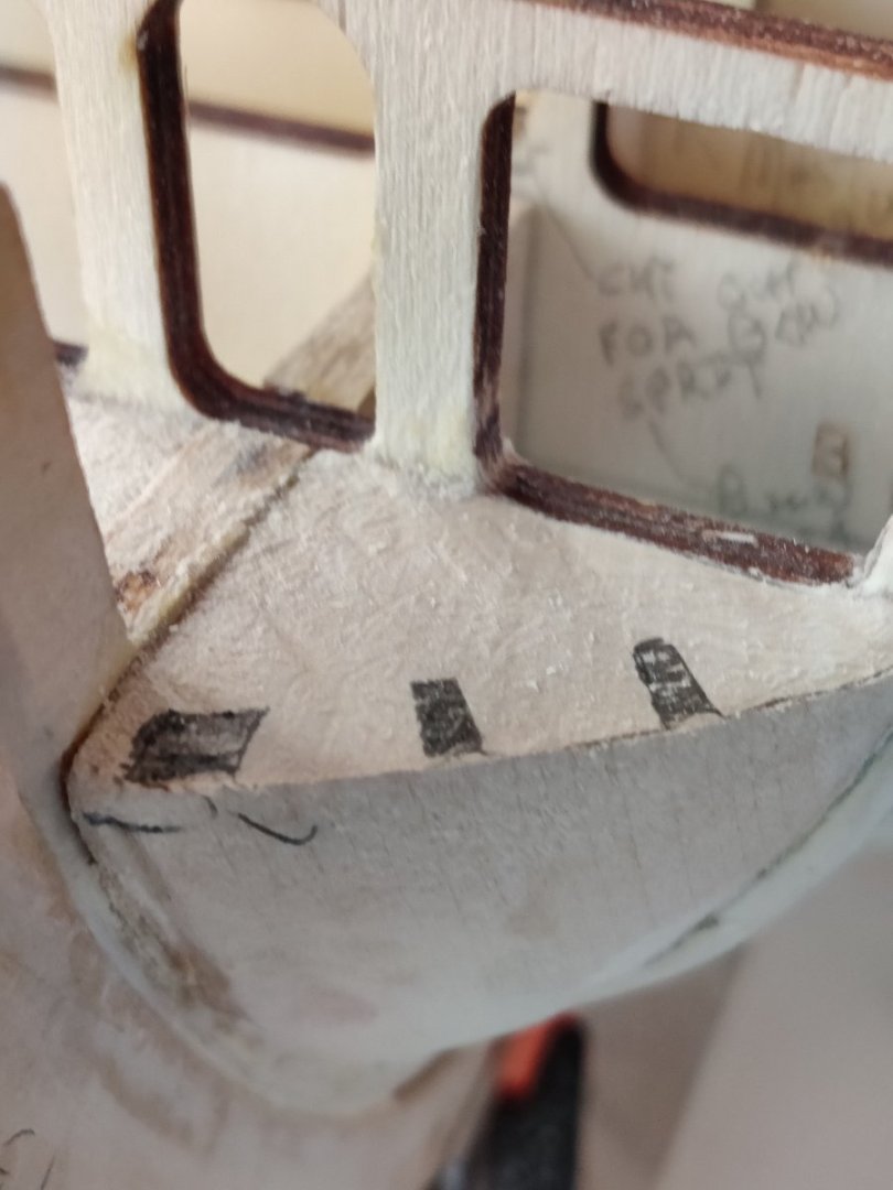
The bow fillers are in and the notches marked for removal. I had to go back to them several times in order to get them reduced enough. I wish I had cut out the pattern for the bow notches earlier because it is a very good guide to ensure you are on the right course. I followed the suggestion by Der Alte Rentner and used a piece of planking to see if it would smoothly fit.
-
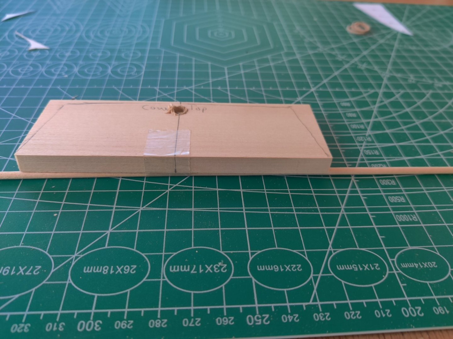
Thanks for the advice Der Alte Renter, I followed your advice and double taped the transom and you were correct I had to reshape the stern blocks twice. I hope it is close. I used the template from Bob Hunt's practicum and I Iooked at your build log. Frankly, your build log was more useful.
-
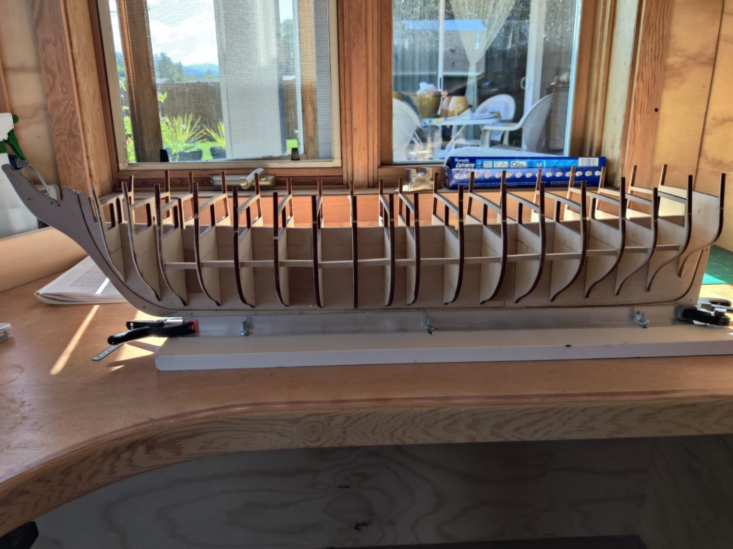
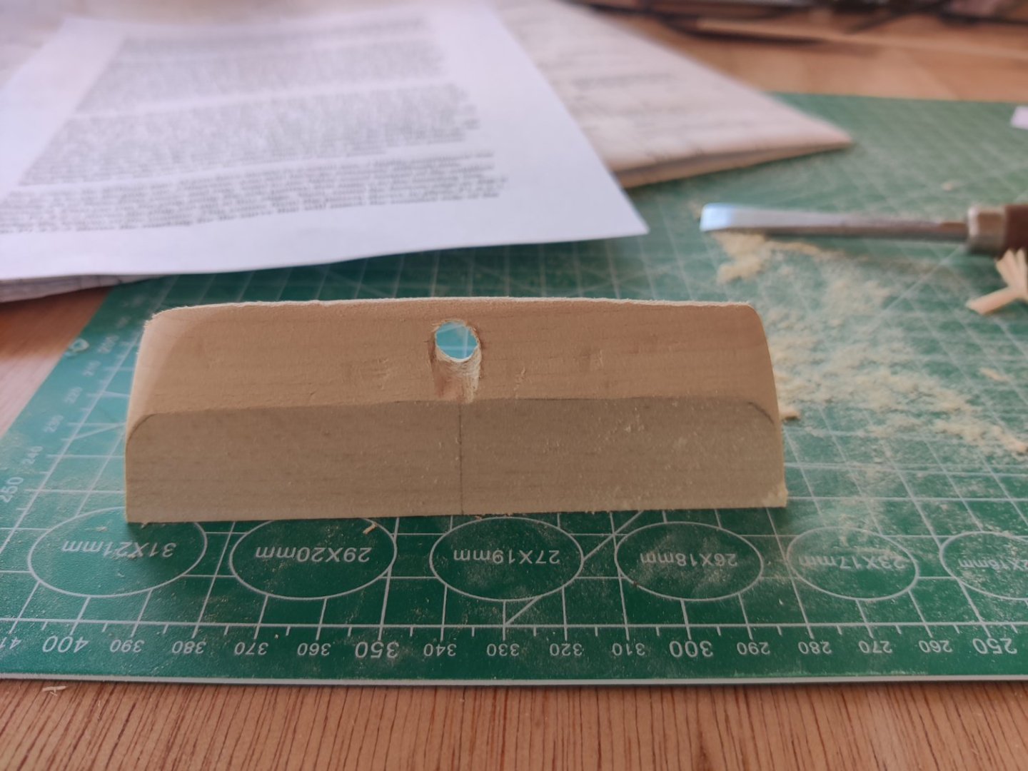
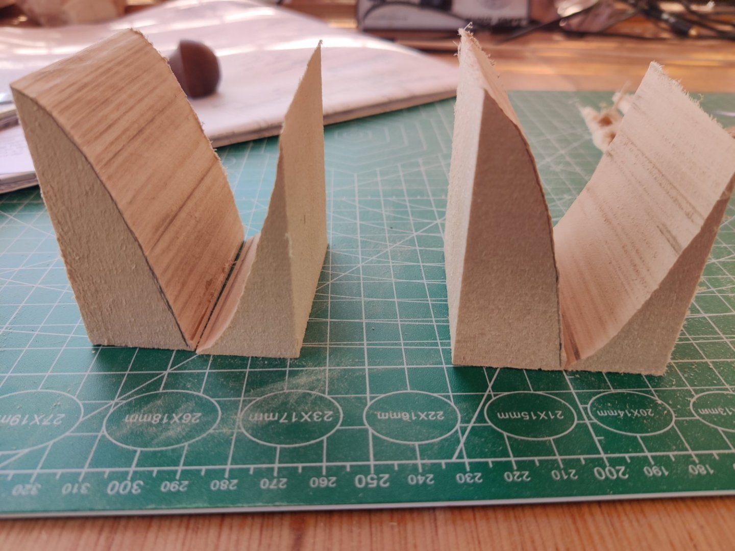
Progress continued over last four days. All the bulkheads have been inserted and glued in, the edges were faired according to the plans, and 3/32x3/32" spacers were inserted. I copied each bulkhead plan, cut it out and transferred the center lines, marked the areas to be faired and trimmed them before inserting the bulkhead. I cut out the transom filler block. Then I placed a 1/8" dowel under the back edge of the transom filler block to grt an angle on the hole. The dowel was too small to get the tight angle so i replaced it with a 5/16" dowel and re-drilled in the rudder hole. I used a power drill and started with a 1/16" bit and then 3/16" bit and then 4/16" bit. I finished it to size with a round wood rasp. I then shaped it with my #1 chisel which is 1/2" wide. Then sanded the corners according to plans. I dry fit it and lined up the center line on the transom filler piece with the center line on the keel and the center line on bulkhead R. I cut out the two filler pieces that fit below the transom filler piece with the bandsaw and then sanded them to the cut line. There were some burn marks from the bandsaw which I sanded out. I clamped the lower filler blocks in place with a small brass bar clamp and marked the edge of the bulkhead on each. I will use 5 minute epoxy on the transom tomorrow and then finish the 2 lower filler blocks.
- GrandpaPhil and tmj
-
 2
2
-
thanks Der Alte Renter so much for responding to my request for help. I will follow your guidance and level the deck area and deal with the fairing issues when time arises. I have inserted 3/32x3/32 spacers between all the ribs as the plans recommend except at each end where the blocks will be inserted. Inserting the blocks is my next item on the to do list.
-
HELP HELP HELP Now I have a problem. I finished putting in all ribs and then learned that on rib section O I did not get the rib aligned with the reference line. It is now 1/16" too high on top and 1/16" too low on bottom. It is solidly glued in. How do i correct it? Do I shim the the lower section and shorten at top? Do I cut out the rib out entirely and cut out a new one from a piece of plywood that is the same thickness? I have a band saw and could try that.
-
I like your solution too.
-
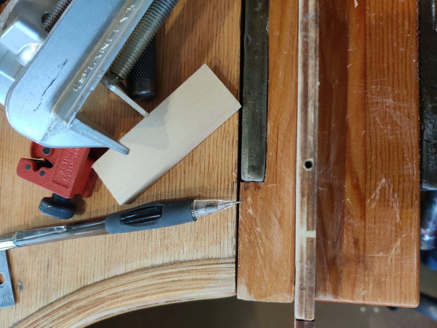
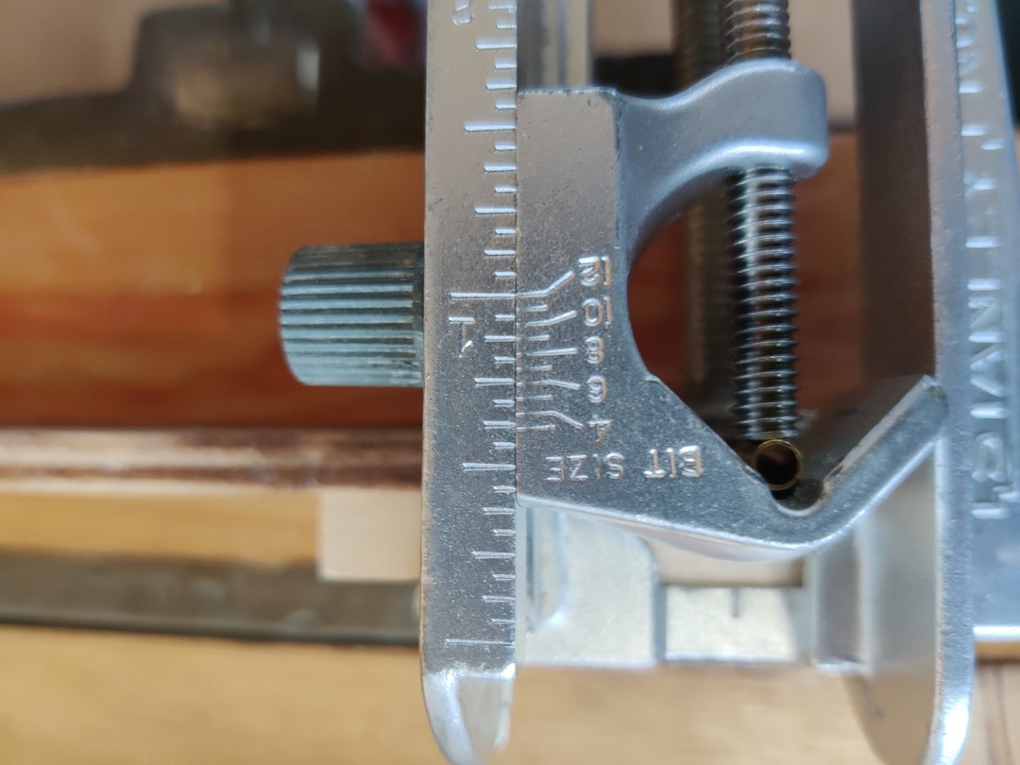
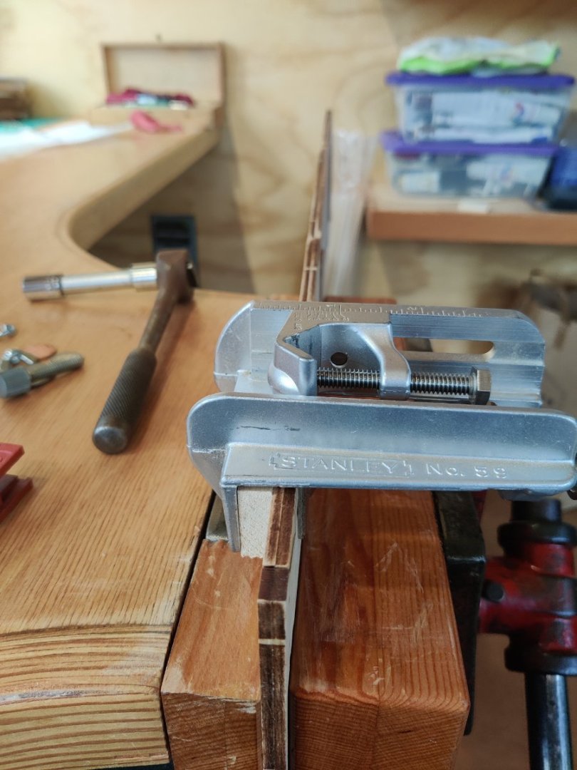
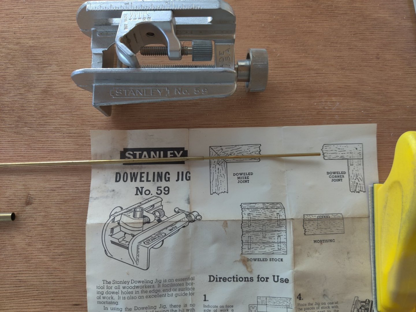
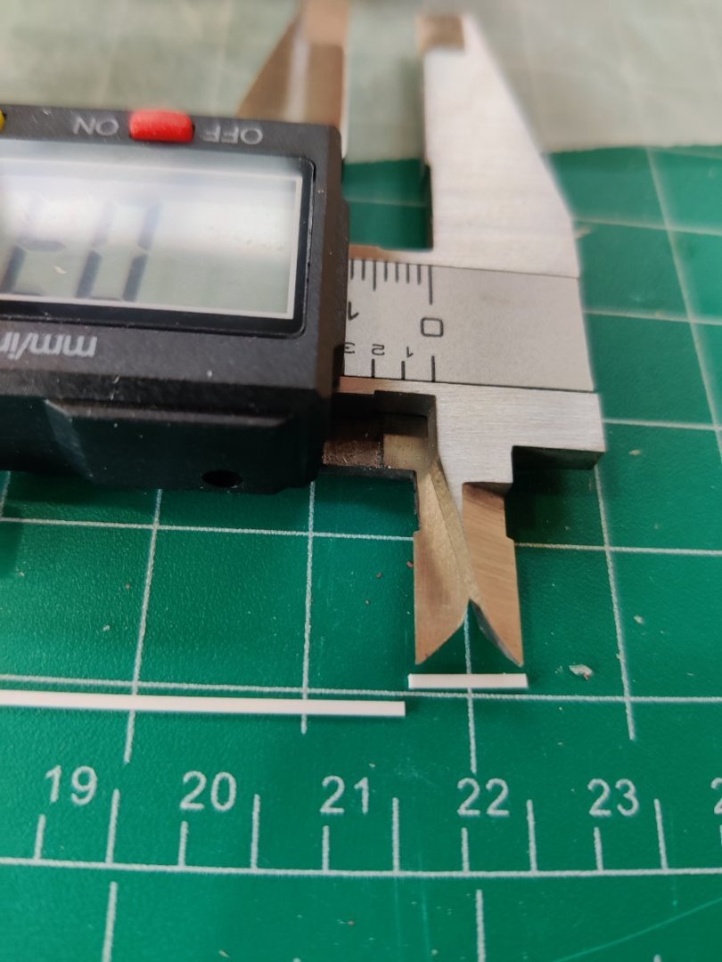
So I tried to use the Stanley dowel jig. Two problems became apparent, one, the jig was designed for a minimum wood thickness of 1/2", the second was that the bolt that held the metal sleeve was two short to accommodate a sleeve less than 1/4". I solved the thickness problem by using a wood scrap as a shim. I got a longer bolt but had to use a socket and socket extension to screw it in. I cut a brass tube with an internal diameter of 1/8", which would be my dowel size, and cut the 1/8" brass tube into 4 one inch sections. when you cut brass tubes with a tube cutter it reduces the internal dimension. So after i cut them I reamed out one end with drill bit so I could use 1" brass tubes on my mounting board that would be inserted into the dowels. So you kill two birds with one stone, you get the reinforcement from the brass dowel and you have a secure way to mount the boat. I put in four brass tubes, three at the joints on the keel, and the fourth one about two inches in from the end of keel piece 5. Now I am ready to start aligning the ribs next. The jig enables you absolutely get a straight hole centered on the keel. and you can set the depth as well. On the first photo you can see the red tube cutter and the shim. On the second Photo you can see the brass tube centered on the keel.
- tmj, GrandpaPhil, mtbediz and 1 other
-
4
-
i really like the painting on the freize. I never thought about painting it before installing it but that is a great idea and I will try and remember that
- Peanut6, Glen McGuire, Ferrus Manus and 3 others
-
6
-
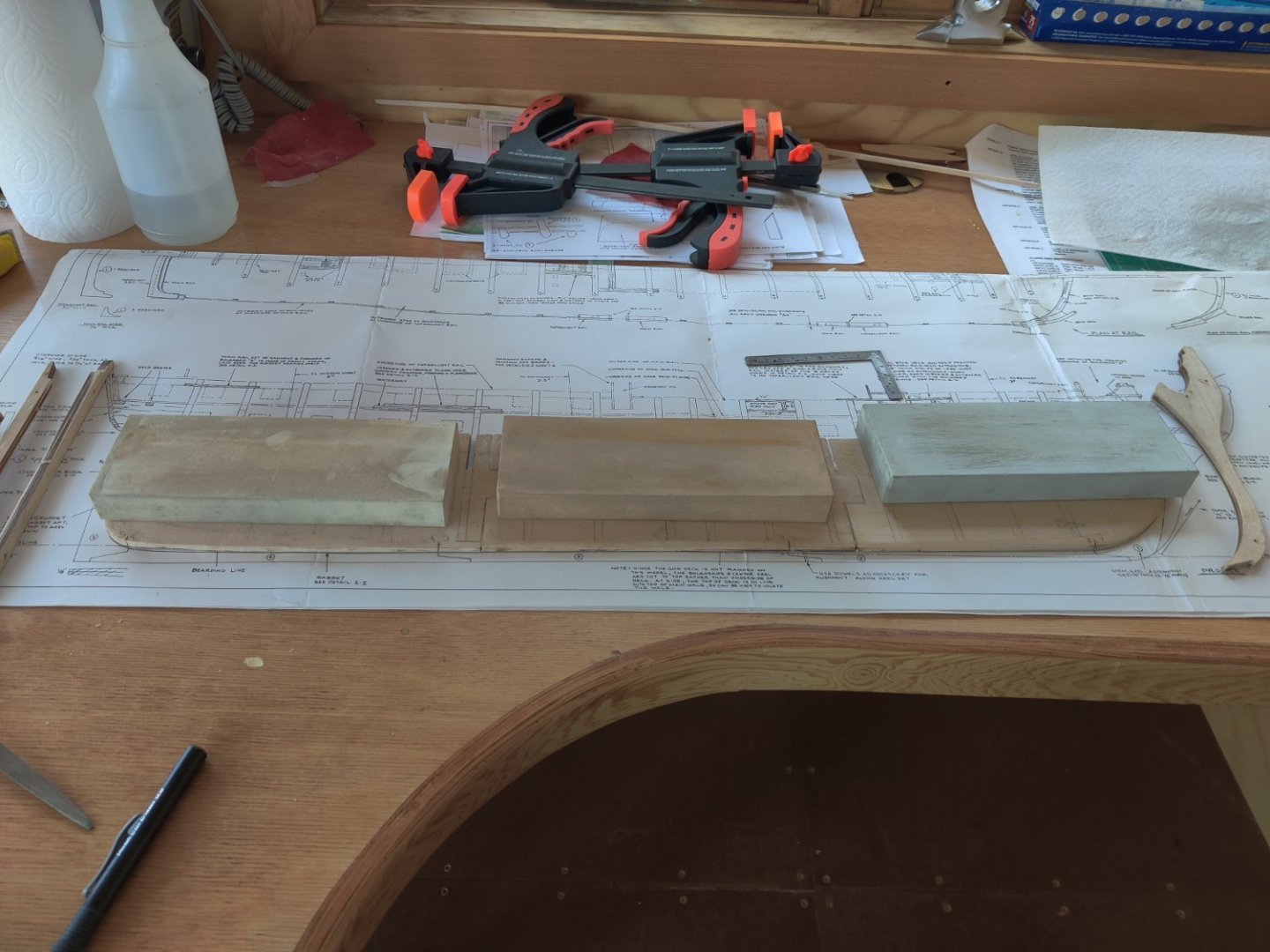
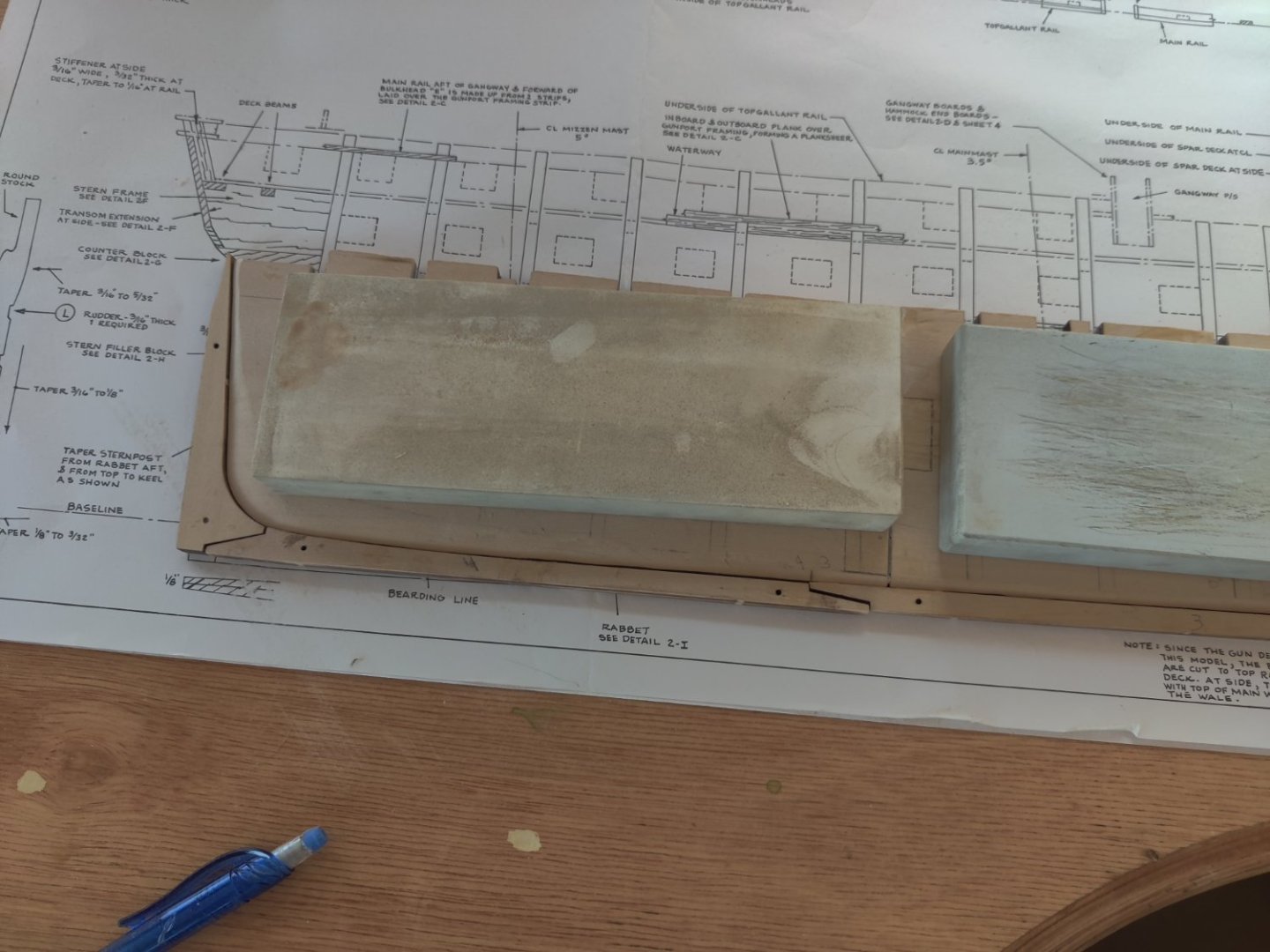
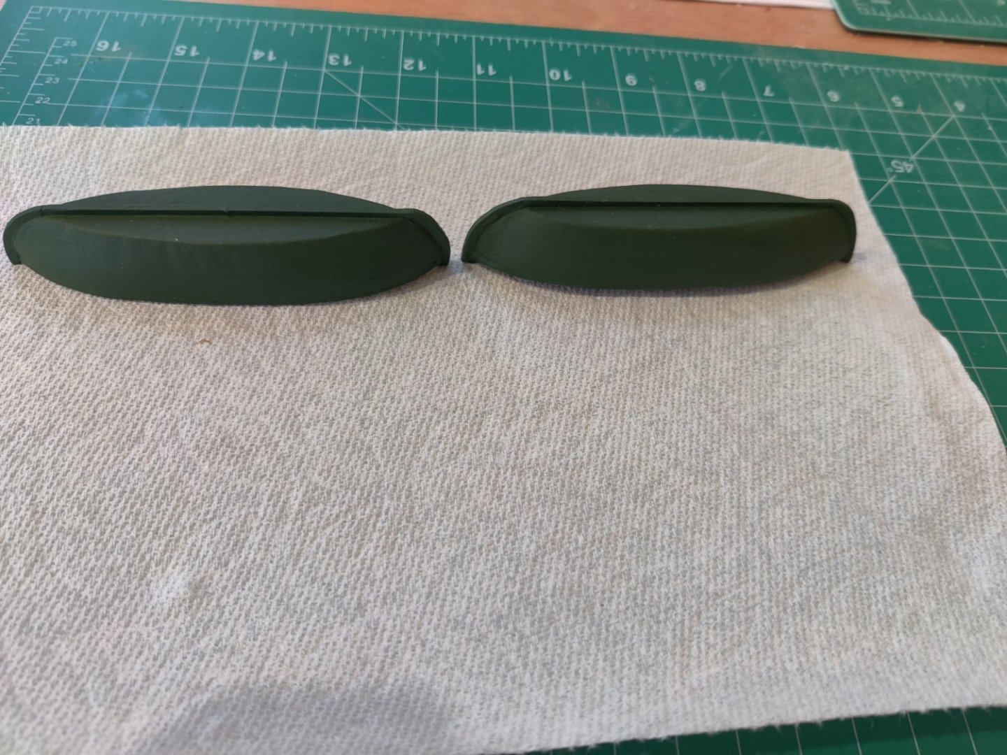
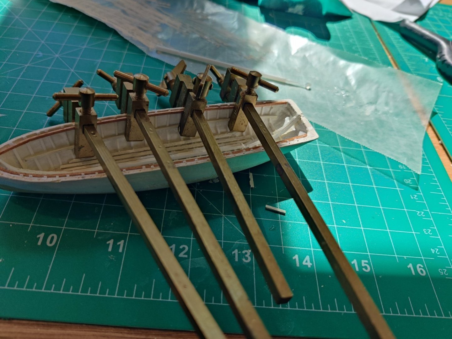
Well the two whalers are as complete as possible until I get some small dowel for the oar locks. So I will move on to the main boat. I finished glue up of the three core pieces and cut in the rabbit. I was fitting the 5 keel pieces on the pattern when I noticed that my rabbit was not deep enough in some areas so I marked those areas on both sides and sanded them until the depth was correct. It was easy to see that they were not deep enough when I laid out the 5 keel pieces next to it. I weighted them down with my sharpening stones. I was thinking about putting dowels in the connection between the keel and the center beam pieces. I saw where others had also installed mounting sleeves in the keel. So i thought about using multiple mounting sleeves as dowels. I do not have a drill press but I have a 30 year old Stanley dowel jig. I was thinking of using the 1/16" bass tube as the sleeve and the solid brass rod that fits inside. I will insert the solid brass rods in the base. i was thinking about using 5 of them. Anyone see any problem issues that could arise from that course of action?
- tmj and GrandpaPhil
-
2
-
-
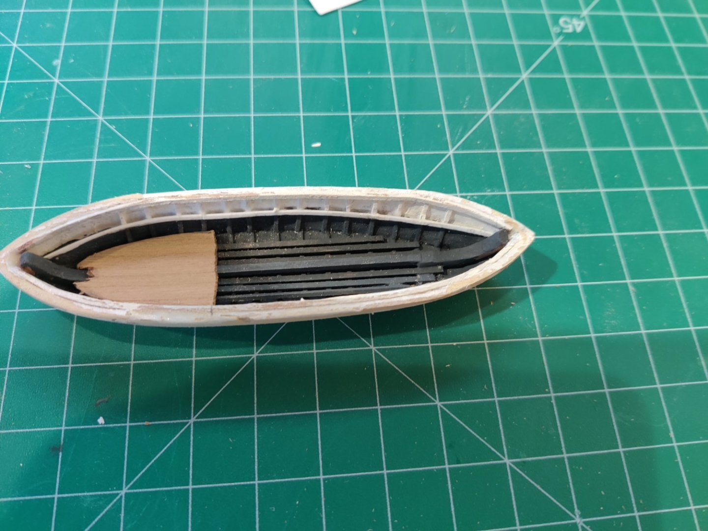
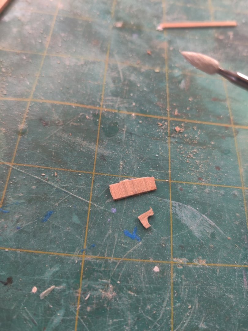
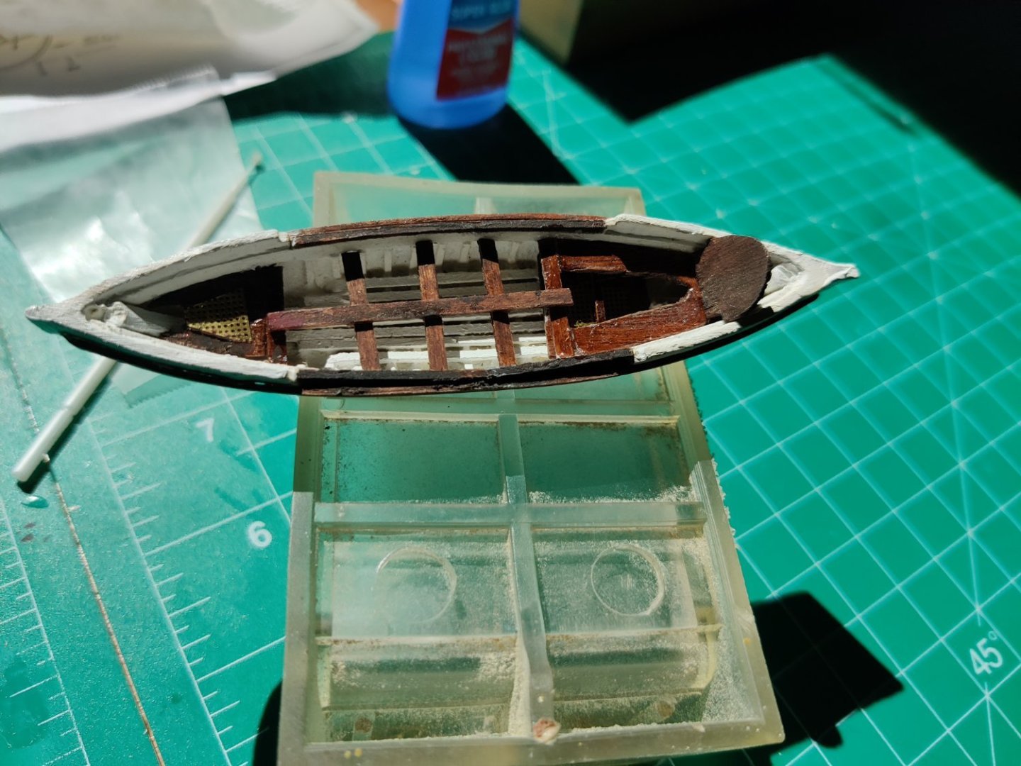
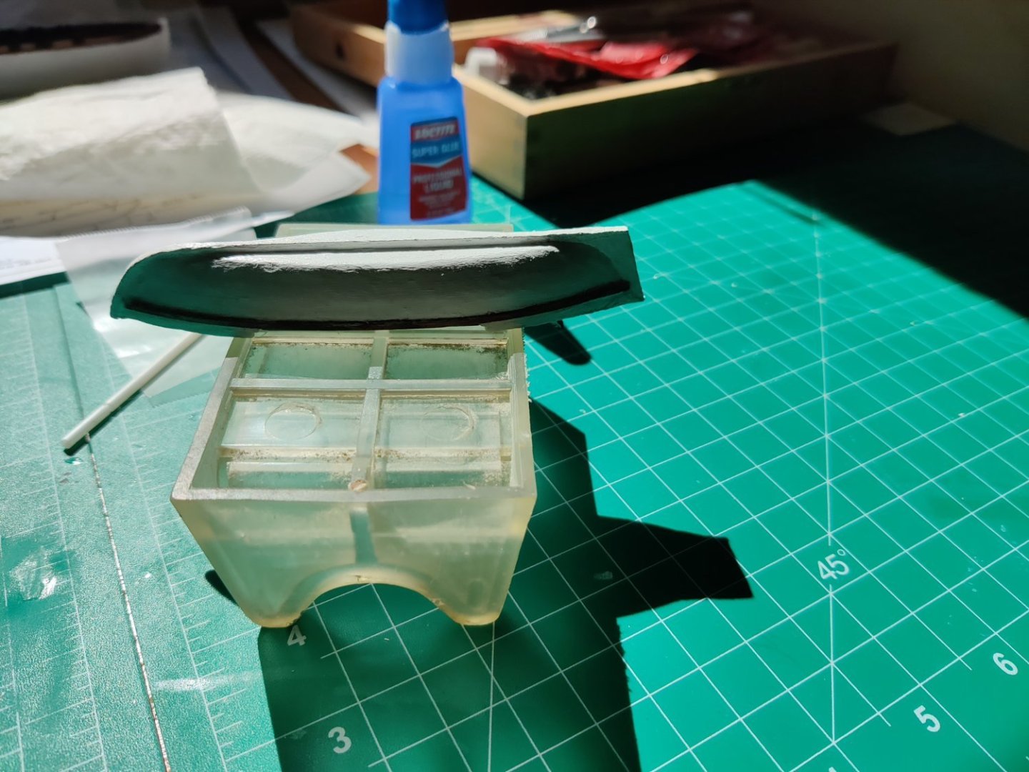
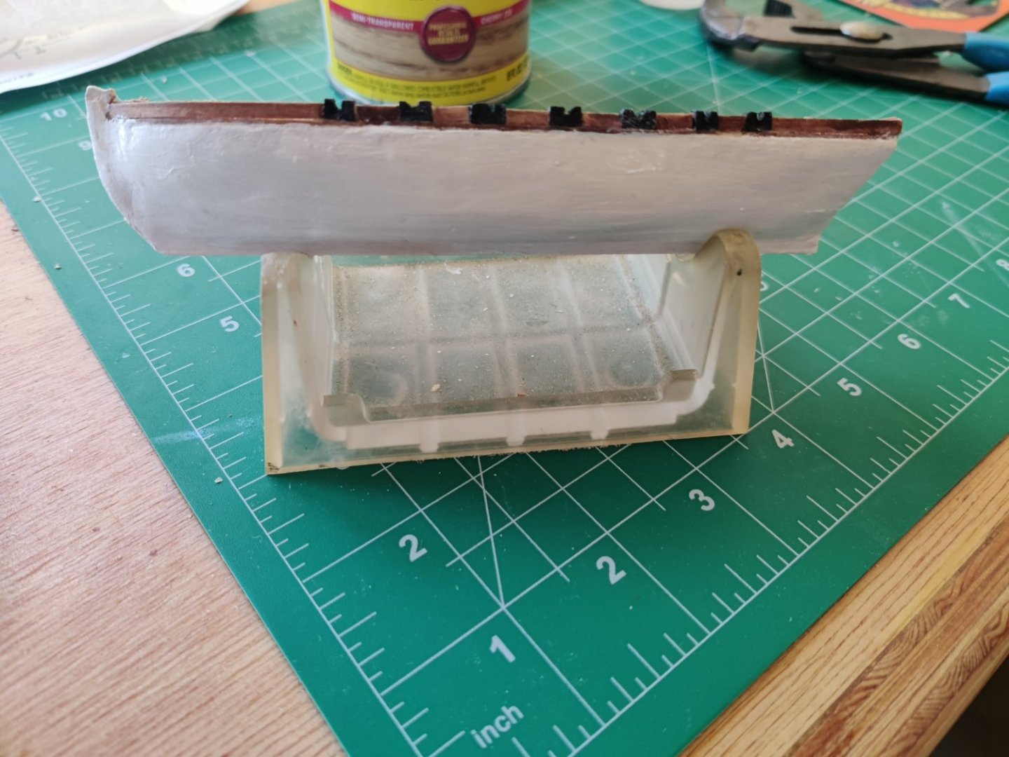
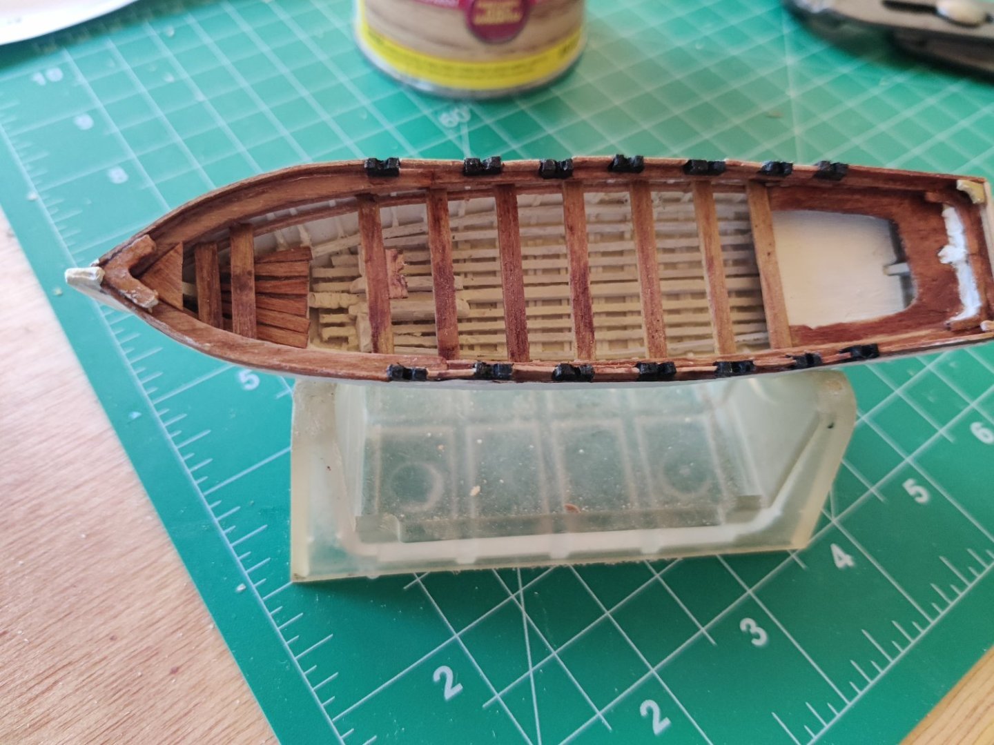
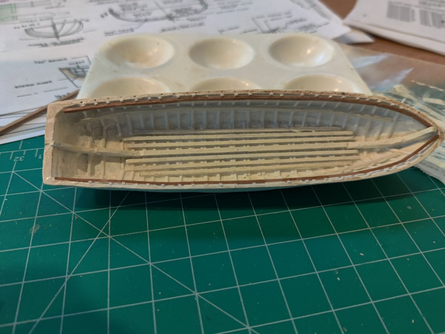
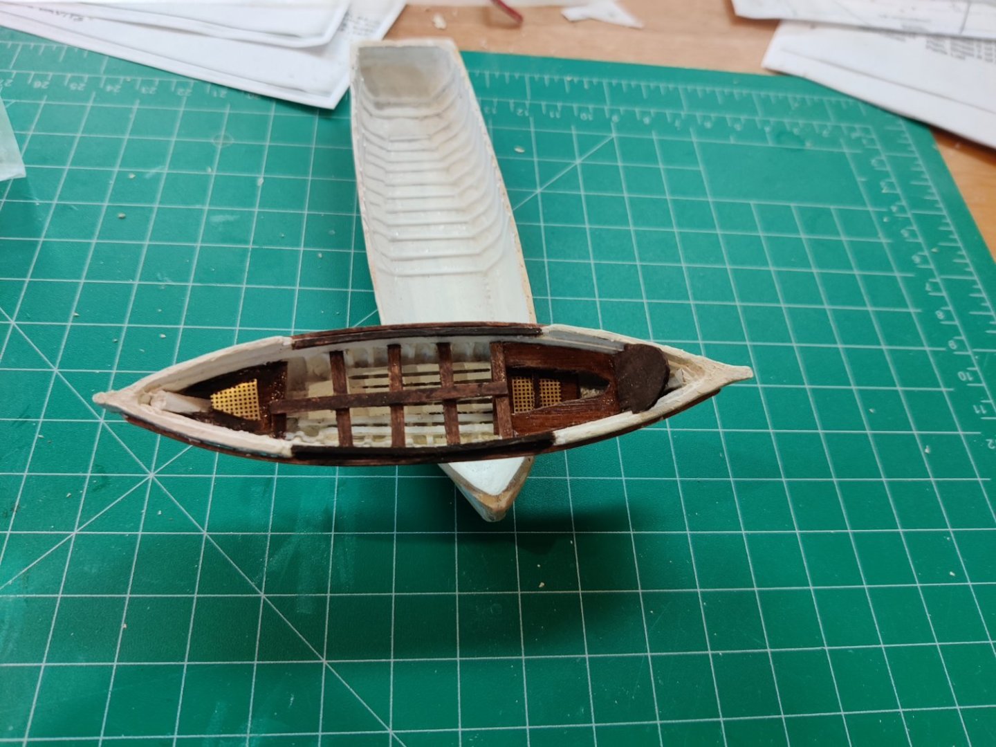
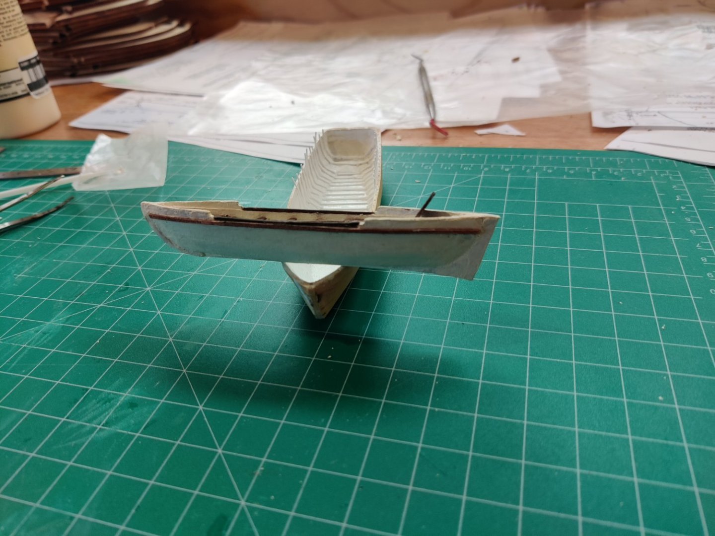
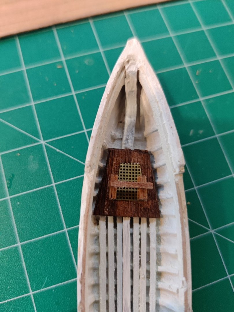
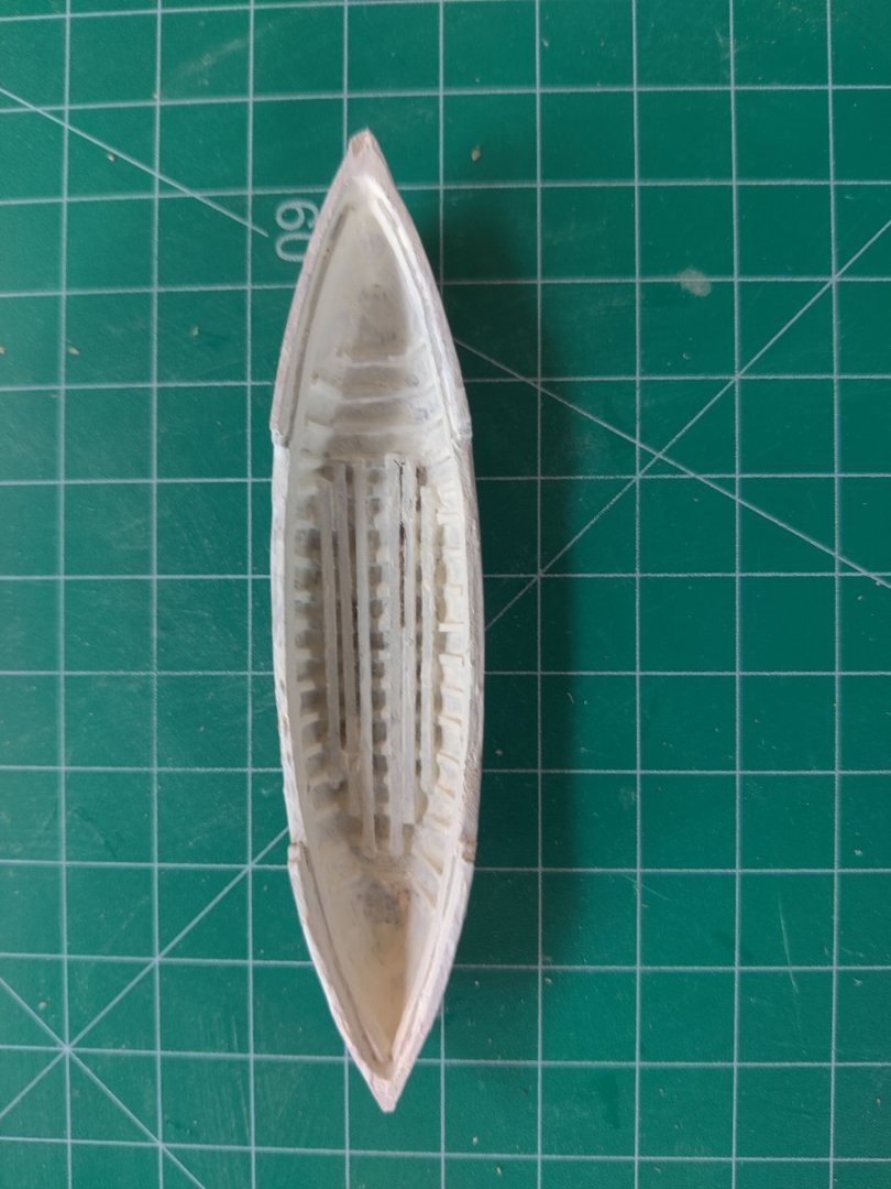
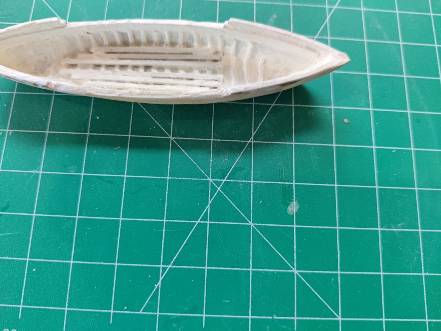
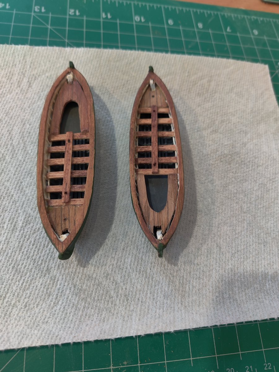
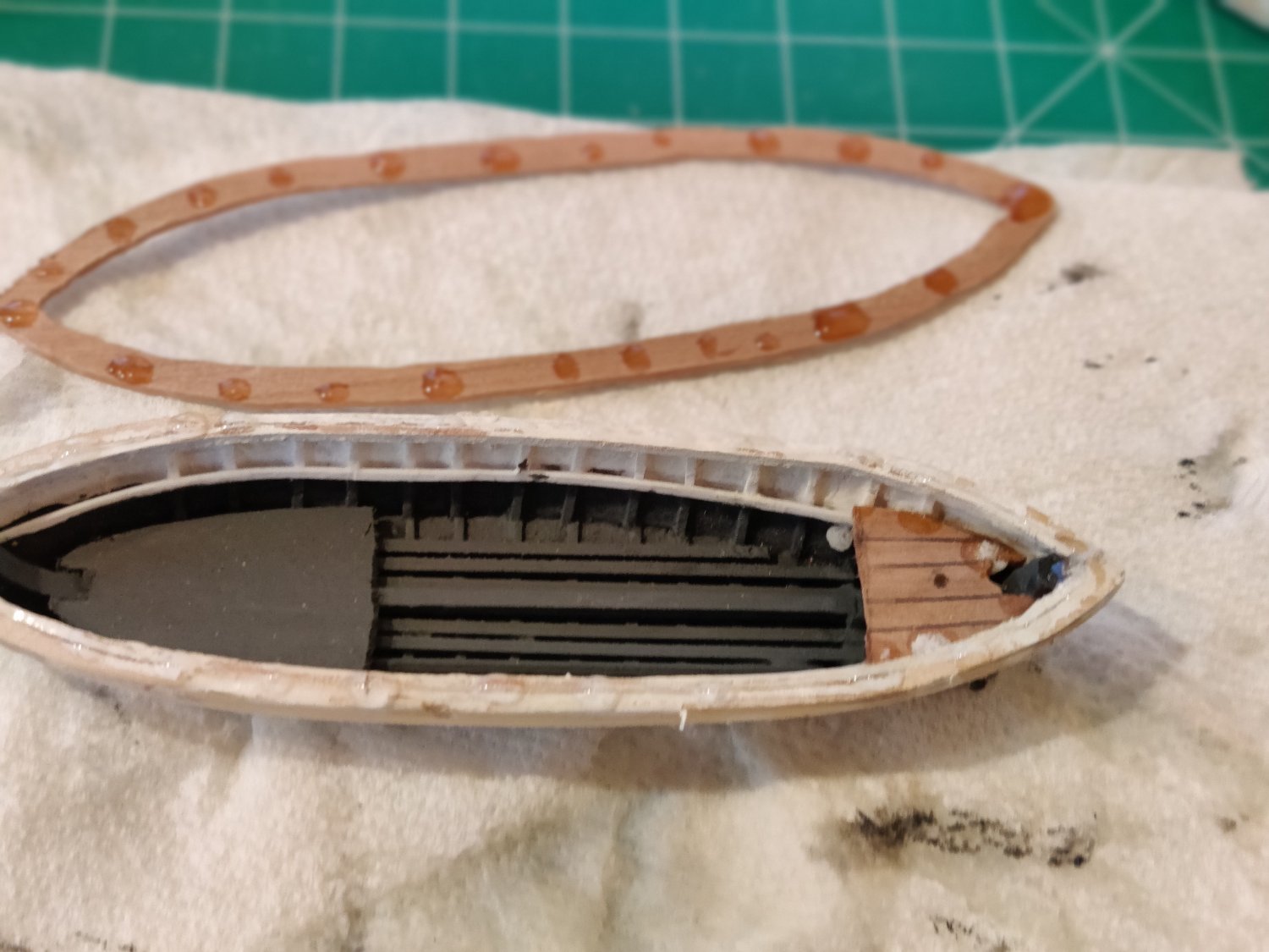
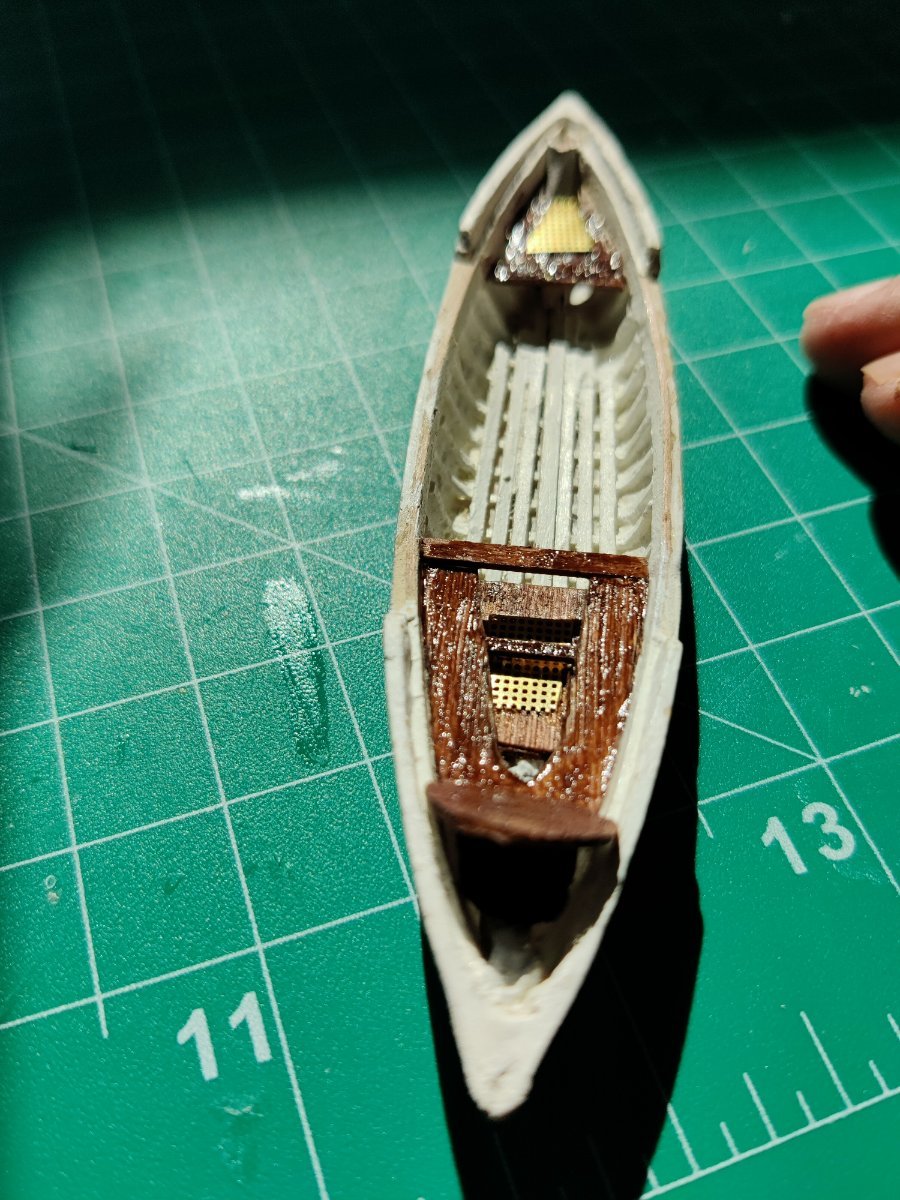
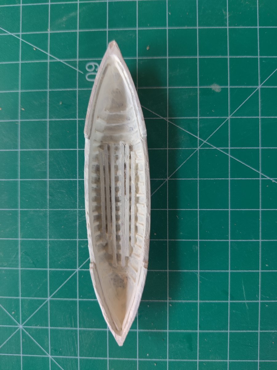
Progress update on the two whalers. I installed ribs and flooring in the same manner as on the gig whaler and the pinnace, although now that I have done it twice it went much smoother and faster. I ran out of the cherry strips that were 3/64" thick that I had used on the pinnace for the cap. However I had a 4" wide sheet of 3/64 cherry. I do not have a table saw to cut strips s I decided to cut the cap out of the sheet. I used the small rotary bit for my power carver to make the rough cut. I then sanded and used round diamond cutter to get the inside and outside edges to size. I glued on the entire cap and and then used a little wood filler where needed so there were no gaps. I cut the the stern and bow knees out of the same sheet of cherry and installed them. The thwarts and gang board are cut to size and I will get them installed tomorrow and get the remainder of the keels inserted. Then I will try and build the oar locks if i ca find a small enough dowel. The dowels supplied with the kit are way to large. I penciled in a line on the cherry at the stern and bow so it appears that two separate pieces of wood were used.


- Knocklouder, GrandpaPhil, tmj and 1 other
-
4
-
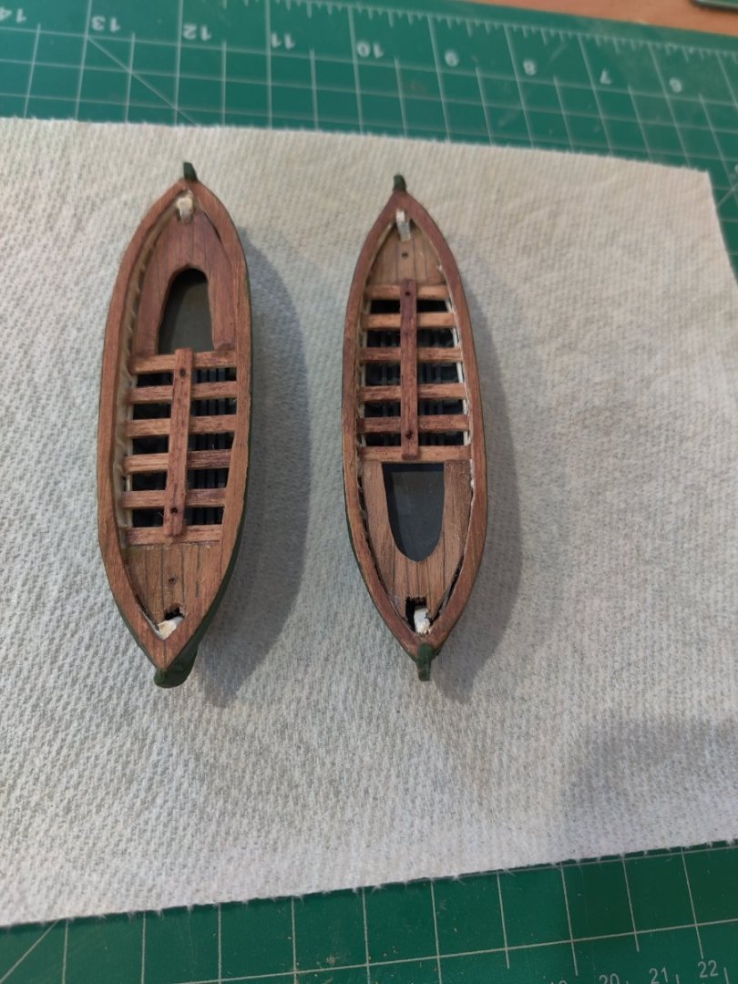
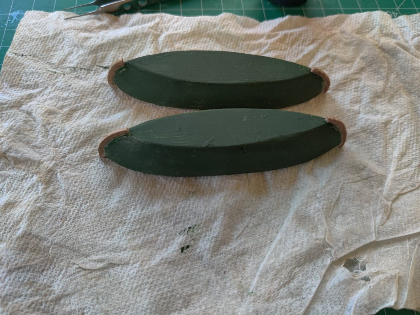
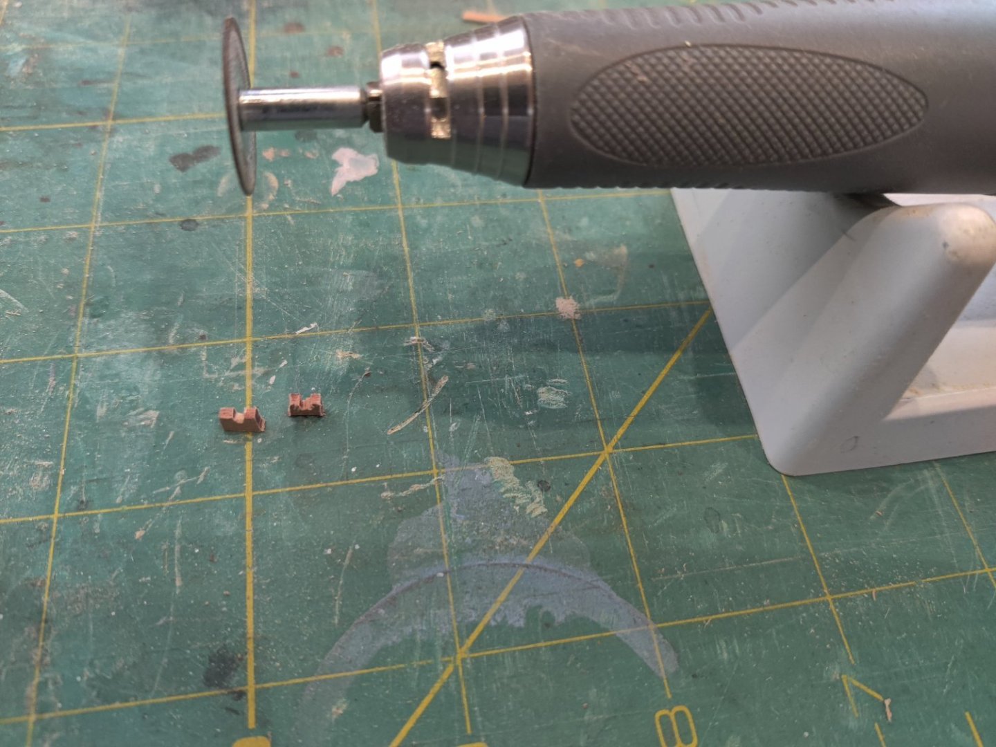
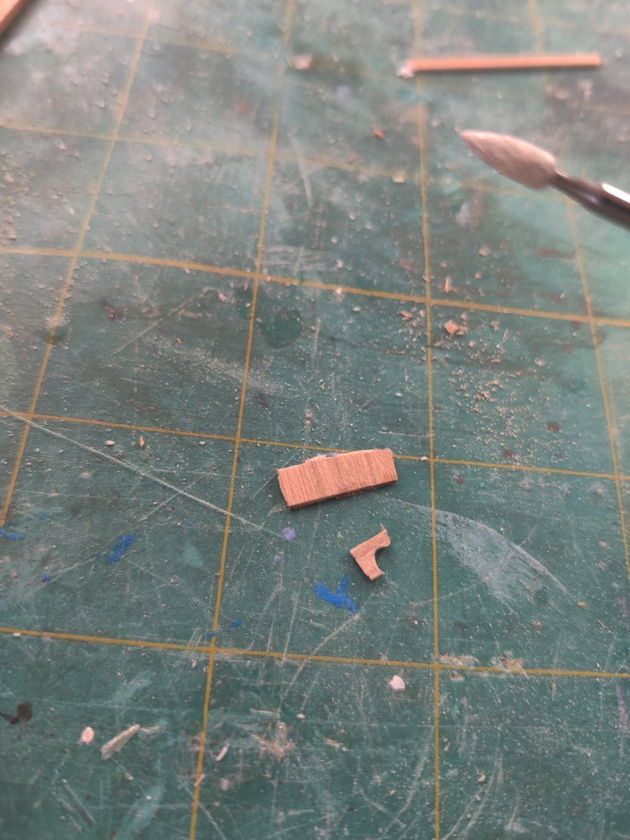
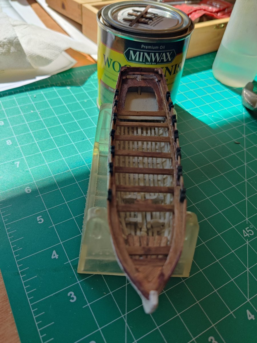
I have finished the pinnace. When it was completed I went back to the gig whaler to fix some problems that I discovered after the last post. when I looked at the pictures, I saw that the keel was not level for its entire length, it was too long on the stern end. So I corrected that and I was not satisfied with the paint on the hull. I took all the hull paint off, re-sanded the hull and repainted with new paint. I used some old paint and the white had yellowed after a few days. I used the same techniques on the pinnace as the gig whaler so I did not document all the same steps. There were some new challenges on the pinnace. The first was how to make the oar locks. JSGerson used a Byrnes table saw to make his. I do not have one so I put a circular cutting bit on my rotary carver and made the small channel in a 1/8 x1/16 cherry wood strip. I put my rotary cutter on its stand and made the channel, then sawed the oar lock off, and then made the next channel. Having a long wood strip to hold onto helped the process. The second challenge was to make the very small corner braces. For this i put a diamond flame bit on my rotary carver and cut a half circle in a piece 1/16" cherry wood and then cut it off with the same cutter bit I used on the oar lock. I have not made the rudders for either boat yet, I will wait and see how the boats fit on the deck before making that decision. I ran out of styrene for the ribs on the remaining 2 whalers. I only ordered 1 package and it had 10 12" strips, I should have ordered 2. I also have not installed the footrests in either boat. Have not figured out how to make them yet. I also have not installed cleats as that metal work is outside my comfort zone.

-
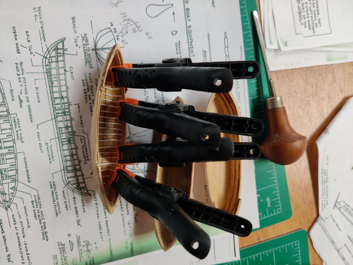
Work is proceeding on the Pinnace. The ribs and footlings have been installed, the keelson was cut out of cherry with my stump cutters and installed. I used the brass bar clamps to install the gunwales and the footing on the sidewall.I learned a lot from doing the gig whaler so the process was faster and and the look cleaner. I used much less glue this time around. Now to install the bench and seating.

- GrandpaPhil, CiscoH, tmj and 1 other
-
4
-
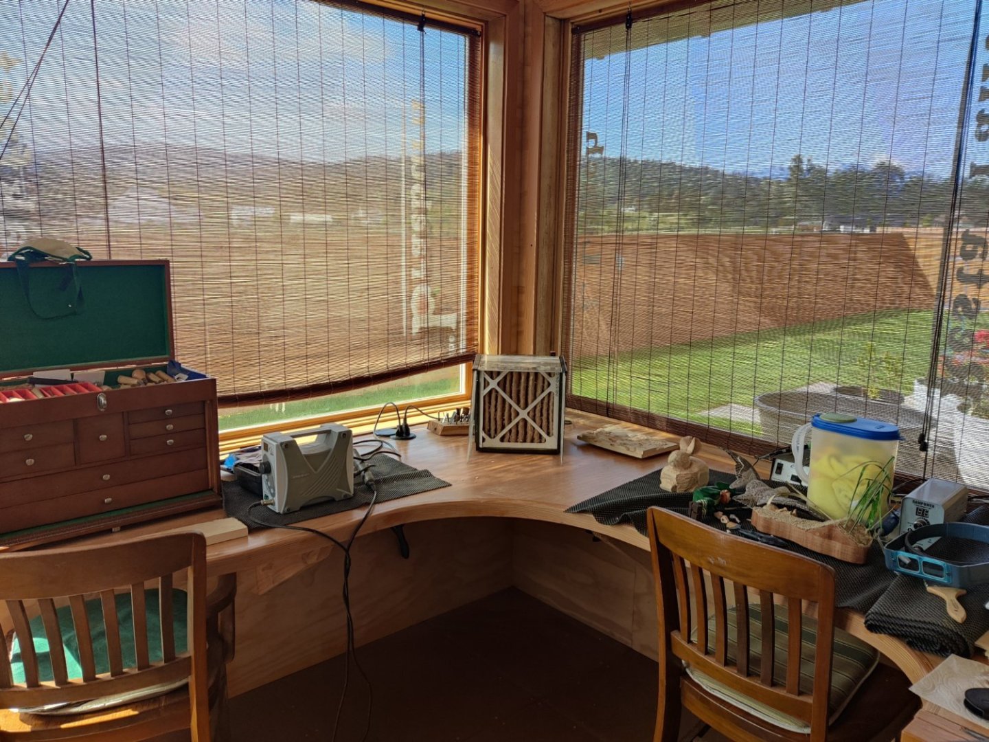
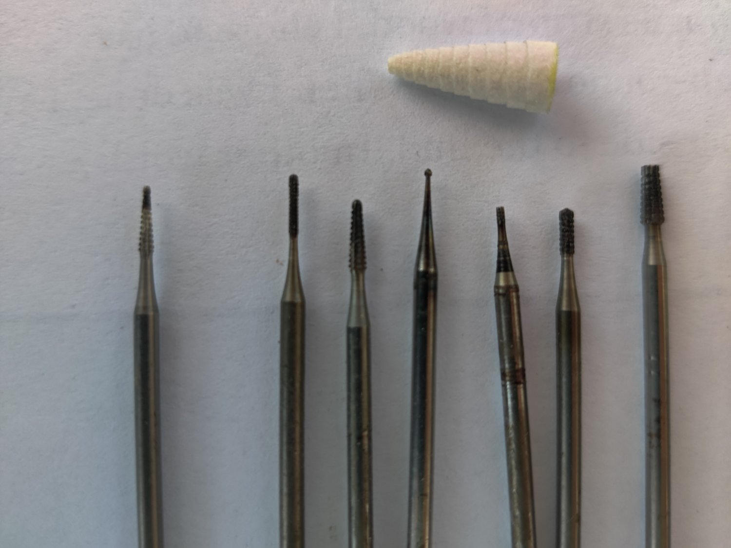
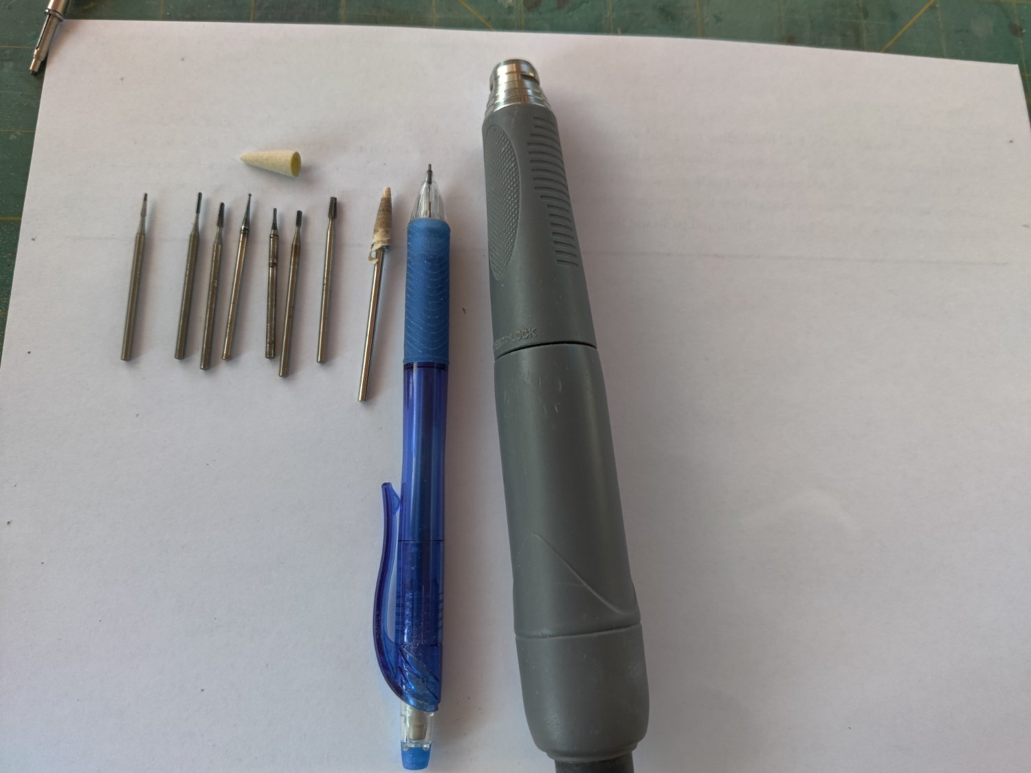
I am a novice ship builder!!! But a very experienced wood carver for 35 years. When I started carving all we used were full size traditional chisels, then palm tools became popular, essentially micro chisels, that could be used with one hand. Then came power tools with a cable and handpiece with carving bits, then brushless handpieces came without a cable and both large and micro bits. I do not have a scroll saw so I started using my micro stump cutters to cut out small pattern wood pieces. These stump cutters are high carbon steel cutters on a 3/32" shaft. The cutters can get as thin as 1/64" and as large as 3/32". If you get 1/8 shaft bits they can get as large 1/4". They are US and German manufactured and cost about $1.15 each from US and $2.25 from Germany. They last a long time if you do not overheat them. My handpiece can run up to 50k rpms without any vibration and is essentially noiseless. It has adequate torque at low speed as well. On 1/32" wood I can run at 3k rpm; on 1/16" at 6k rpm, at 1/8" I can at 12k rpm and at 1/4" at 30k rpm. There are micro sanders at 120 and 180 grit. They are cone shaped and as a they ware out they get smaller but still sand. The bits will work in a Dremel but not very elegantly. If you do not have a scroll you should try it. Pictures of the tools and my home shop below.


- Canute, Boccherini, mtaylor and 3 others
-
6
-
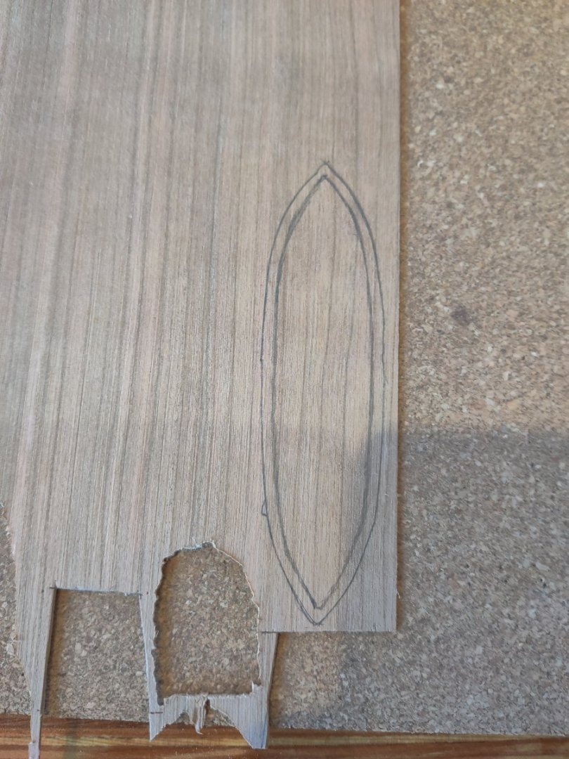
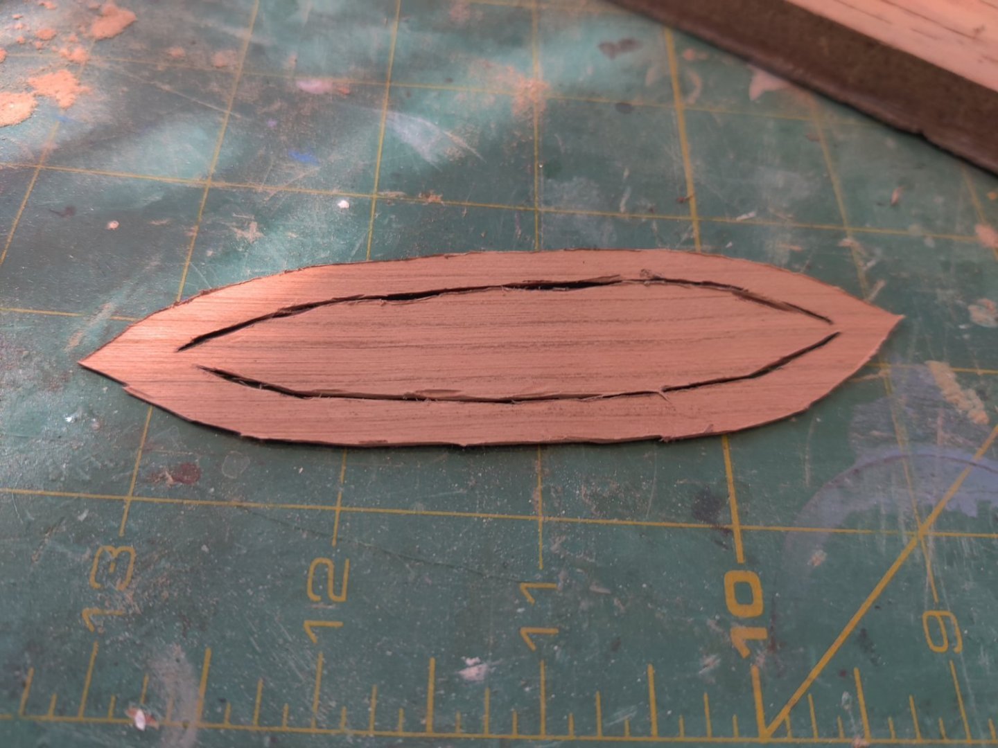
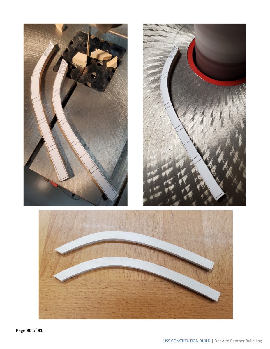
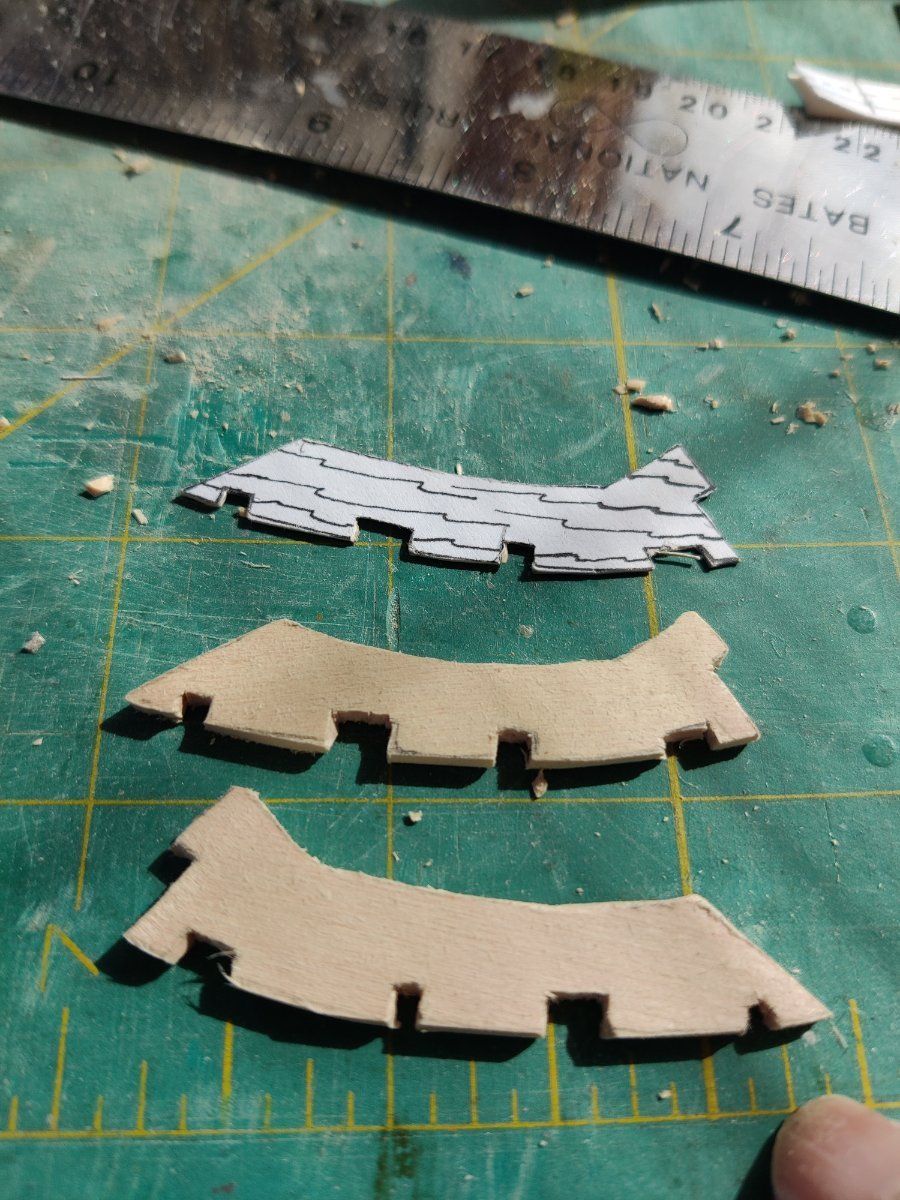
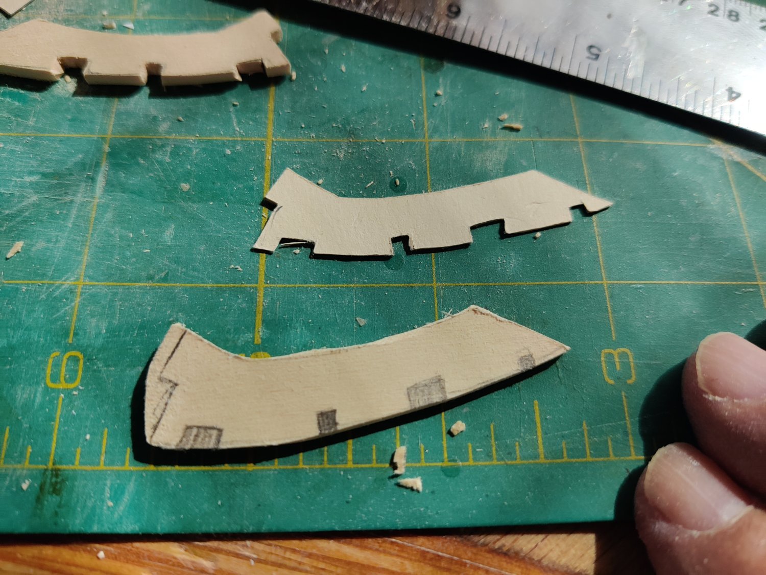
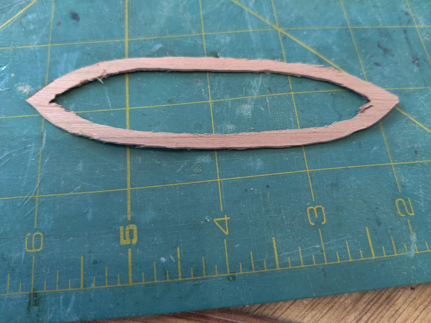
well I have completed the gig whaler. I have added all the details that my skills permit. I did not add the cleats, the rudder or the oar locks. I soaked the fender pieces in water and then pinned them to the plans to dry. I failed to take a picture of that so I included one on my pennace that I used the same procedure. I am considering putting on a couple of coats of water based poly but am not sure if I should. Now I will continue with finishing the other three boats. The keel was a real challenge, I made a template out of card stock, but it took three tries before I could cut them out without breaking them.

- Sjors, GrandpaPhil, tmj and 1 other
-
4
-
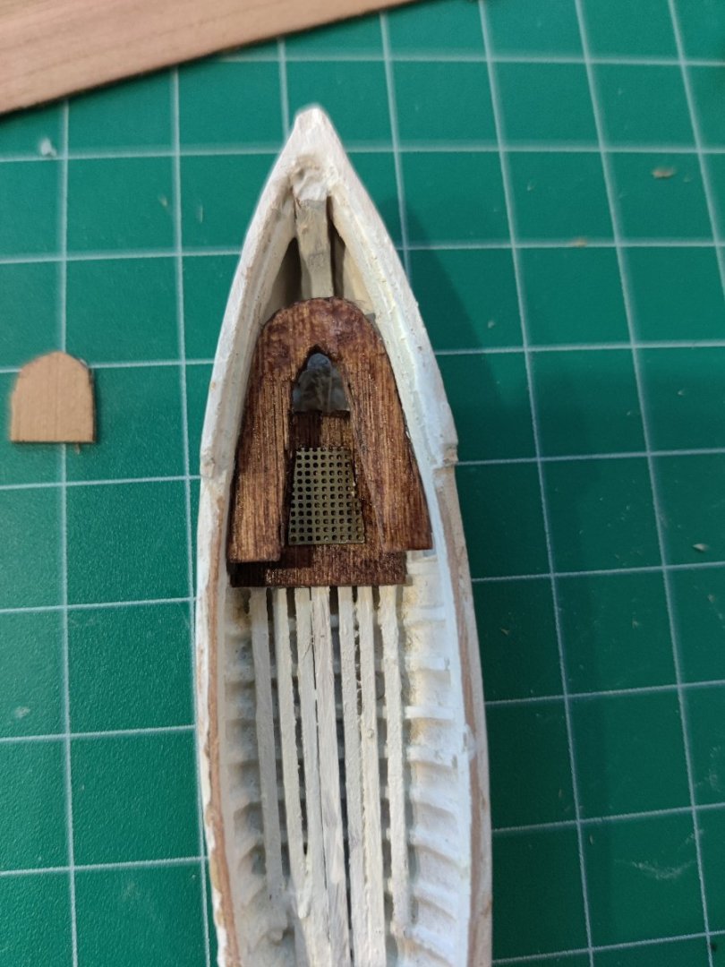
progress on gig whaler
I had some cherry sheets that were 1/32 and I used the to create the flooring, and the seat. I used the the brass grate provided with the kit. I also installed the keelson. The interior was painted with two coats of acrylic white paint and the seat and footings were stained with mahogany stain. Next steps put in the back rest, the remainder of the seats and foot rests. I have decided that it is beyond my capabilities t put in all the metal fittings that were so perfectly done by JSGerson. I only have use of one arm and I have to be realistic about what I can do with one hand. I had to redo the foot rest in the picture and use smaller dimensional lumber, I have finished the ribs in one of the two 28' whalers as well. More pictures to come tomorrow hopefully.
- Sjors, tmj, Snug Harbor Johnny and 1 other
-
4
-
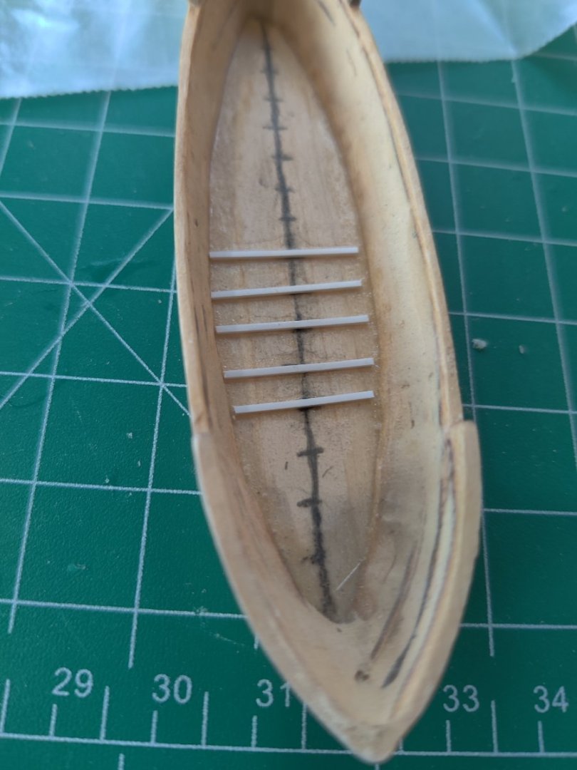
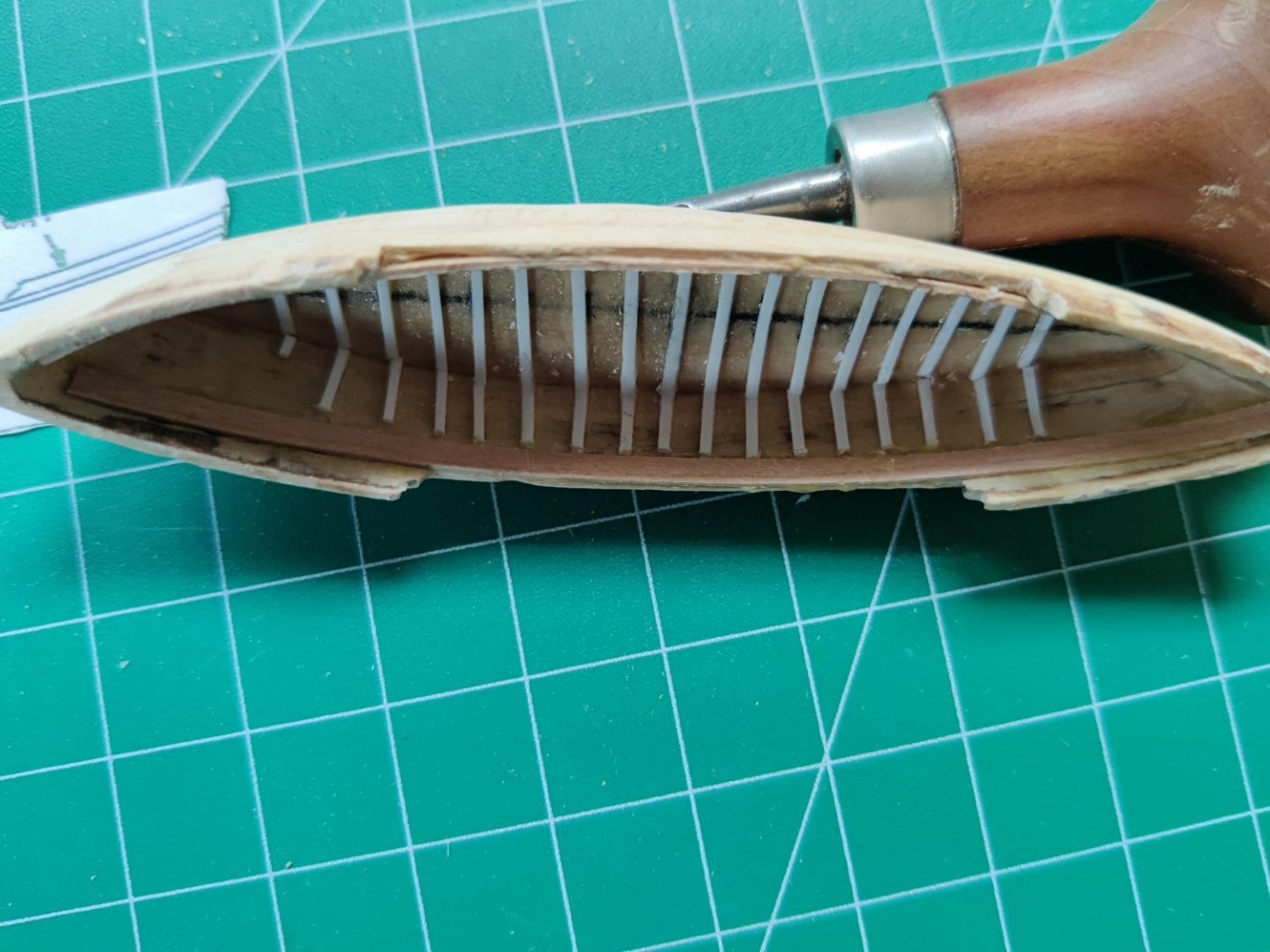
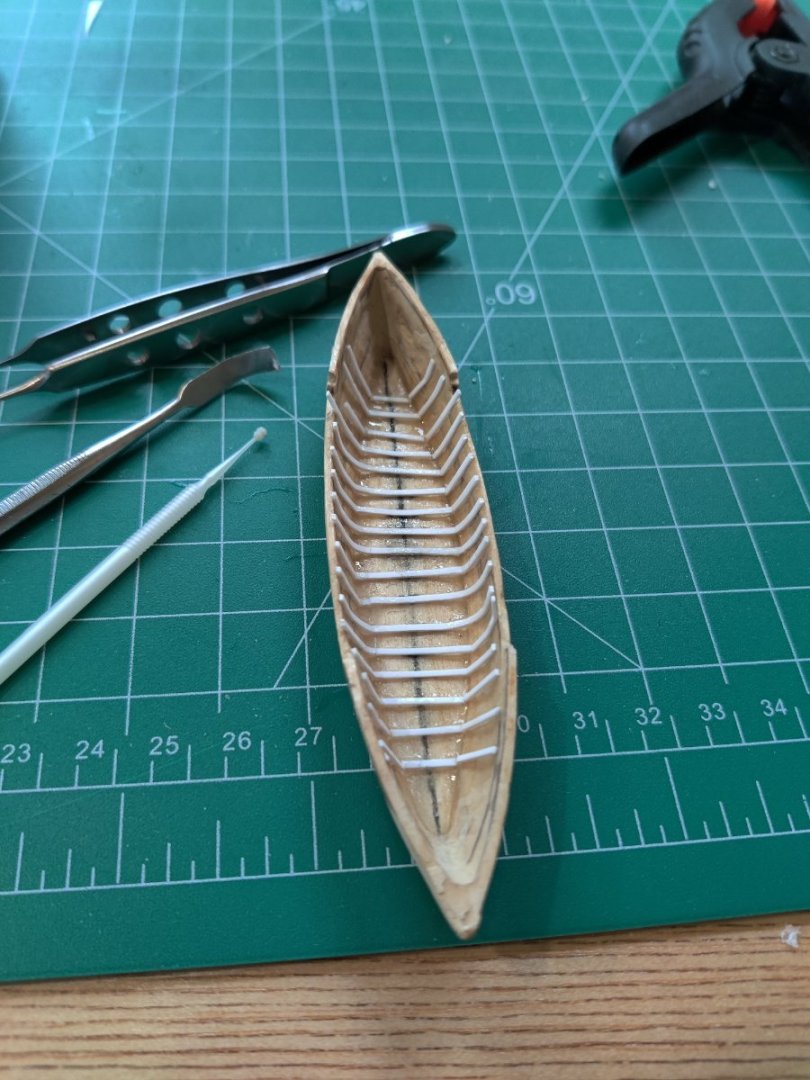
progress on gig whaler and whaler
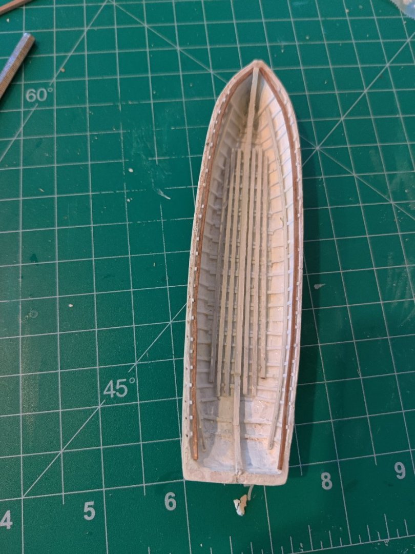
I have inserted the footlings in the gig whaler and painted the interior. On the whaler, I tried another method of putting in the ribs, which seems to be working better, it is more accurate and easier. After drawing the center line, i draw in the location of each rib, then I put one drop of super glue and using a micro plastic glue stick I spread the glue in a straight line, then I use the tweezers to drop the measured rib into place, then press it down. I will repeat the same process on each side wall. I tried putting the entire rib in one piece on the gig whaler but they often broke and it was hard to keep it straight.
- tmj, CiscoH, Thukydides and 1 other
-
4
-
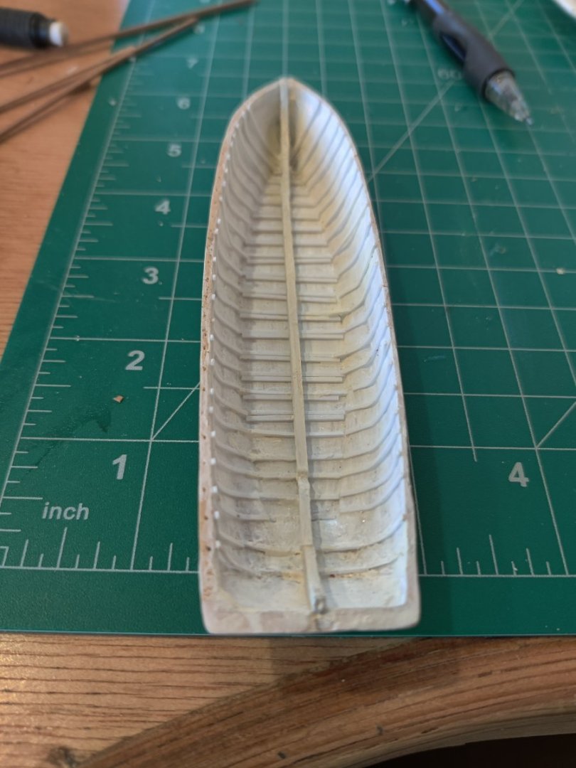
I have completed the ribs and the gunwale on the gig whale boat. I used the Evergreen Styrene strips .020x.040 (No. 122) as recommended by Gerson and others rather than wood. There are 10 strips in a package, I ordered one package, and found out I should have bought two. One is not enough to do all 4 boats. Is is very time consuming to install the ribs and tiny tweezers and a plastic toothpick or glue stick is needed to coax them into place. They are not in perfectly and even though I tried to use a spacer to get them even, I just could not keep the distance uniform. When I got them i place with the spacer, and then removed the spacer to glue the they moved. I was afraid to put the spacer back in for fear that it would be glued in. I will finish the other three boats to this point before installing the keelson and flooring. There is no pattern for the keelson, so I will freehand it. At first I made the ribs too long, when I realized that the gunwale had to be fitted in. So i shortened the ribs I had installed and marked the location of the bottom of the gunwale and put the rest of the ribs in.


-
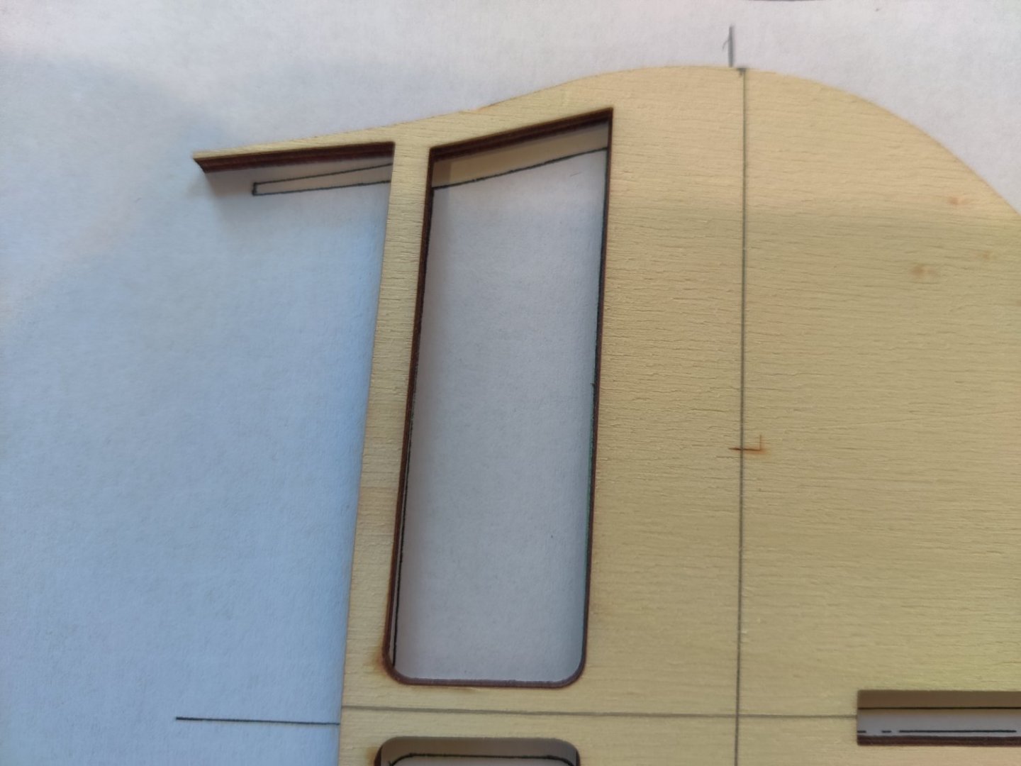
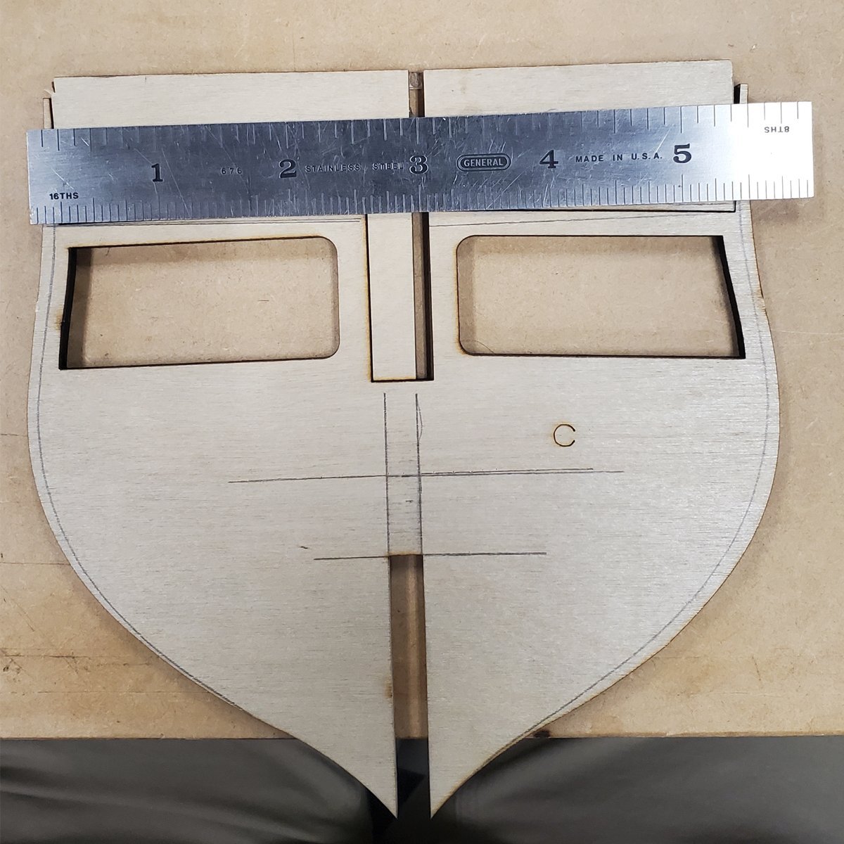
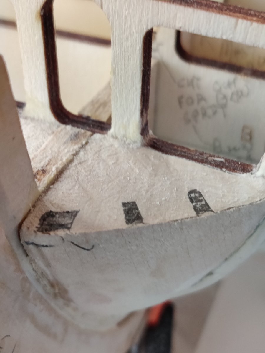
I have noticed two repetitive differences between the plans and the actual bulk heads. The bulk head is taller than the plans on the top and shorter than the plans on the bottom. Is that anything to worry about. See photo below. the picture does not show the bottom of the notch but it is always shorter.
than the pattern. thanks for your guidance


HM Bomb Vessel Granado by Jorez de Saint Nazaire (François) - Caldercraft - 1:64
in - Kit build logs for subjects built from 1501 - 1750
Posted
The planking us stellar/awesome!!