realworkingsailor
-
Posts
3,281 -
Joined
-
Last visited
Content Type
Profiles
Forums
Gallery
Events
Everything posted by realworkingsailor
-
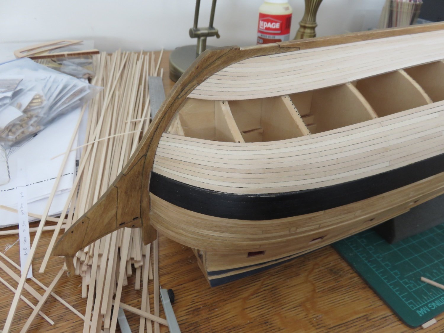
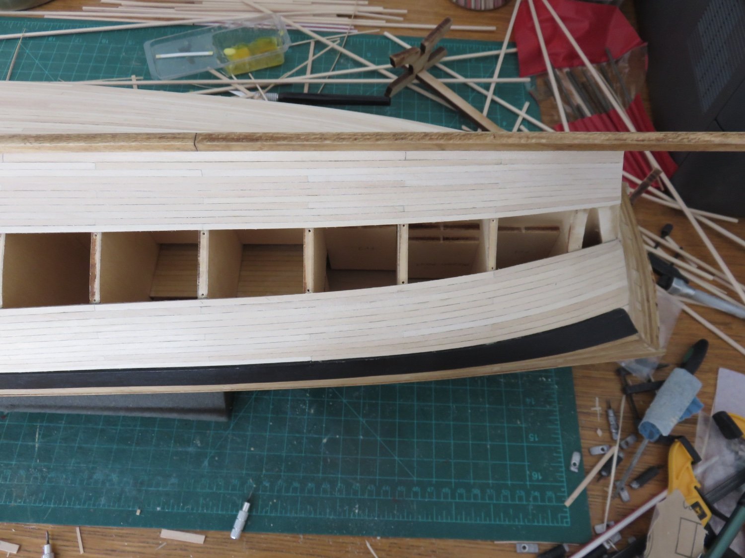
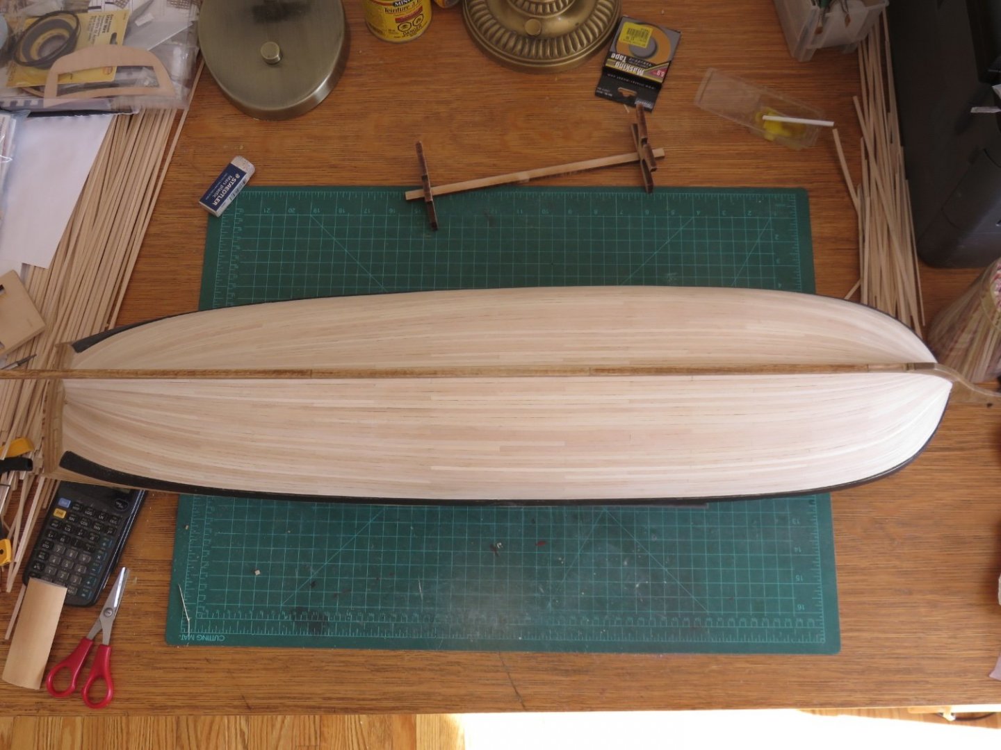
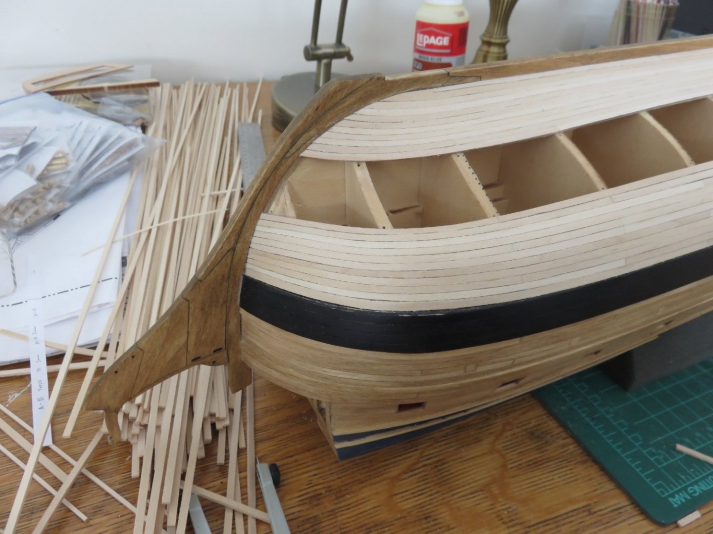
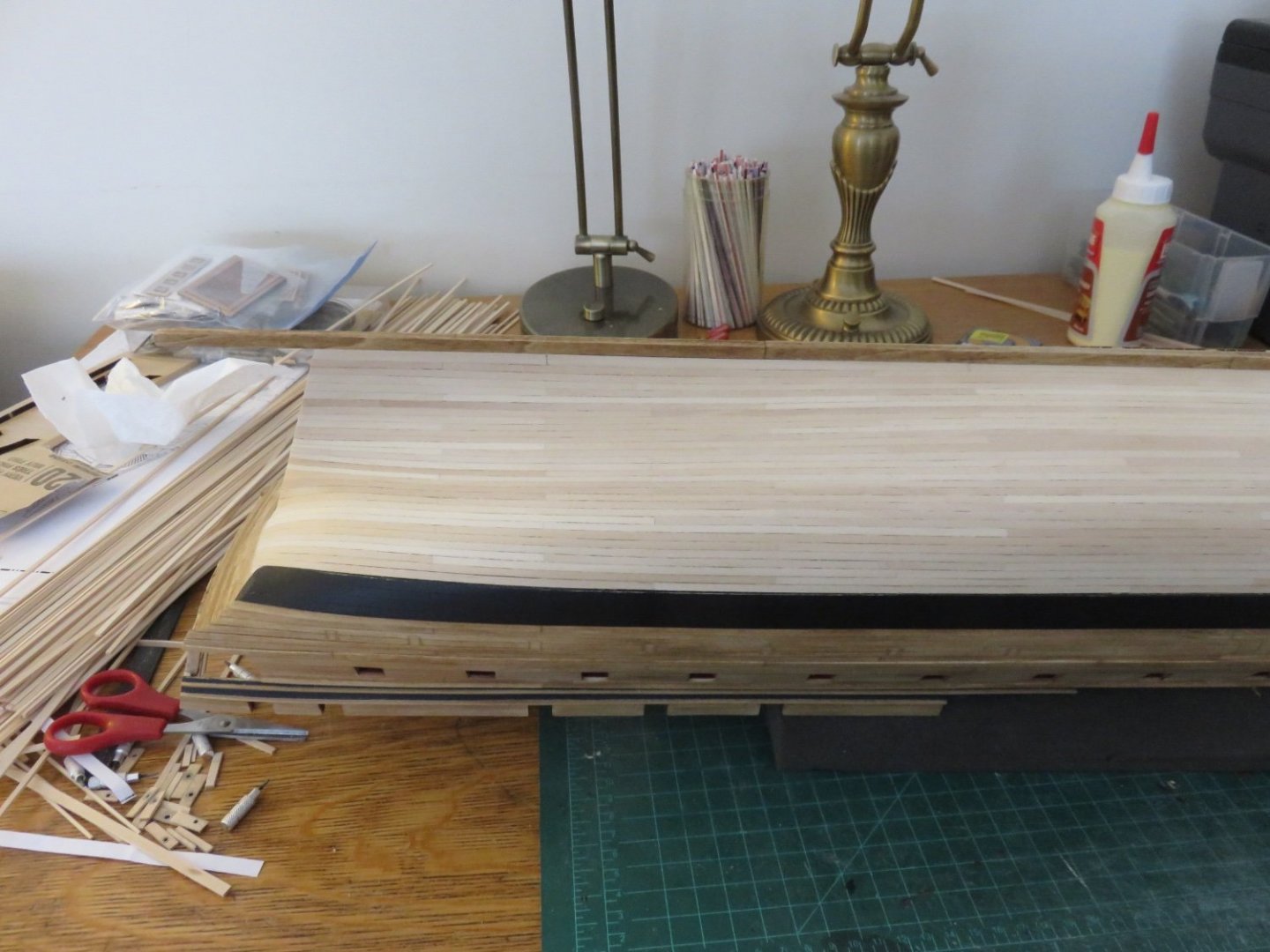
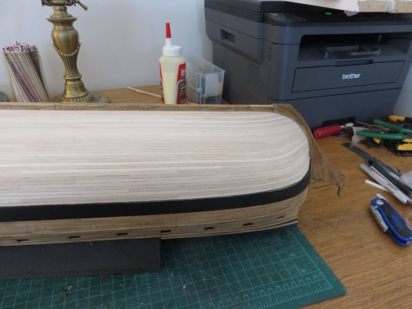
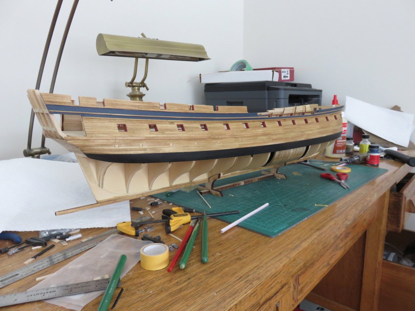
 Thanks to everyone for the kind comments and likes! Yesterday was a bit of a milestone day. The hull planking is finally finished! Hooray! As you can see, I decided to fully plank over the reveal section. It partly came down to personal preference, and partly because over the course of the several years that I have been building (storing, transporting, shuffling aside) the model, some of the frames segments had accrued some small dings and dents (a small drawback of basswood). I've just completed prepping and staining the stern post, so while that dries, time to grease up the old elbow and get making some dust! I really enjoy the sense of satisfaction one gets when a hull has been completed, and I am particularly enjoying the relief that comes knowing I don't have to go all over it again with a second layer (big "YAY"!). Andy
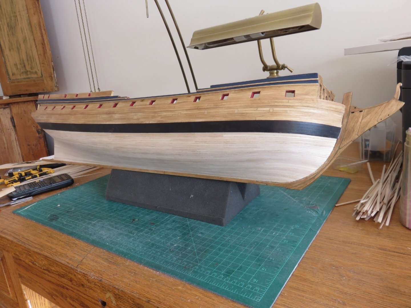
-
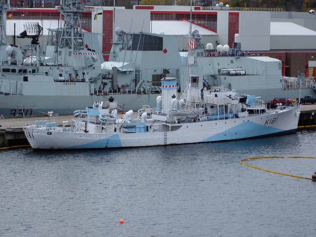
Sackville is only a year newer😜 I was more trying to help with the smoke cans on the stern, which are visible on her. Was there some drastic change in equipment? Andy
- 321 replies
-
- 5
-

-
- Finished
- Flower-class
- (and 1 more)
-
Would this help: (HMCS Sackville for those who are curious) There's a closeup photo in this article Andy
- 321 replies
-
- 8
-
-
- Finished
- Flower-class
- (and 1 more)
-
Thanks! I got those clamps years ago from Lee Valley tools. I don’t know if they still sell them. Try searching for “miniature machinist clamps”, or “tool maker’s clamps” see if that works. Andy
-
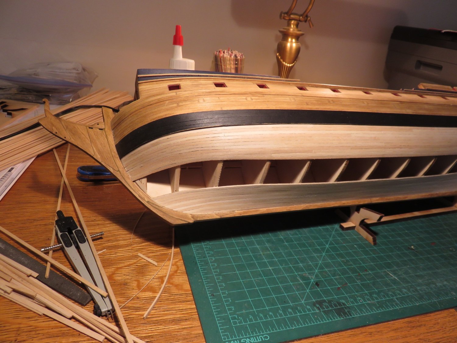
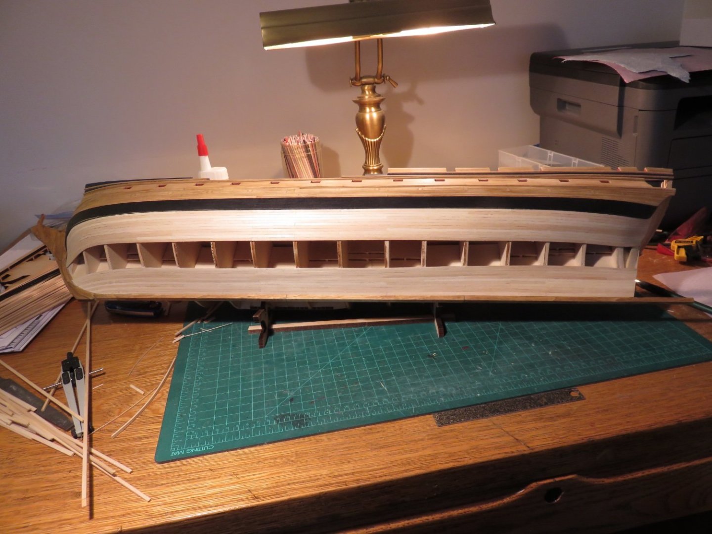
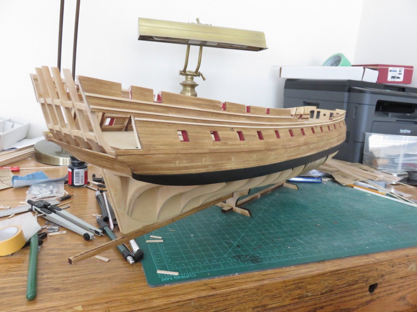
A few weeks since my last update, so just a quick one to show that I'm still working away at it. Construction has slowed slightly since winter finally arrived a couple of weeks ago. Lots of fun outdoor activities, like skiing, sledding, snowshoeing, all the fun stuff that can only be done with a decent amount of the white stuff. And then for those who follow my non-maritime adventures, there's also the odd time when my main mode of transportation decides to no longer function as designed. Anyway, on the days not filled with other activities, work has progressed on the starboard side, and I've now managed to complete the first two planking belts. It's nice to begin to see the (hull) planking finish line. Andy
-
The interior of ballast tanks (of that era), if they were coated, probably would have been a coal tar type paint: black. Andy
- 79 replies
-
- 3
-
-
- SD 14
- Marcle Models
- (and 1 more)
-
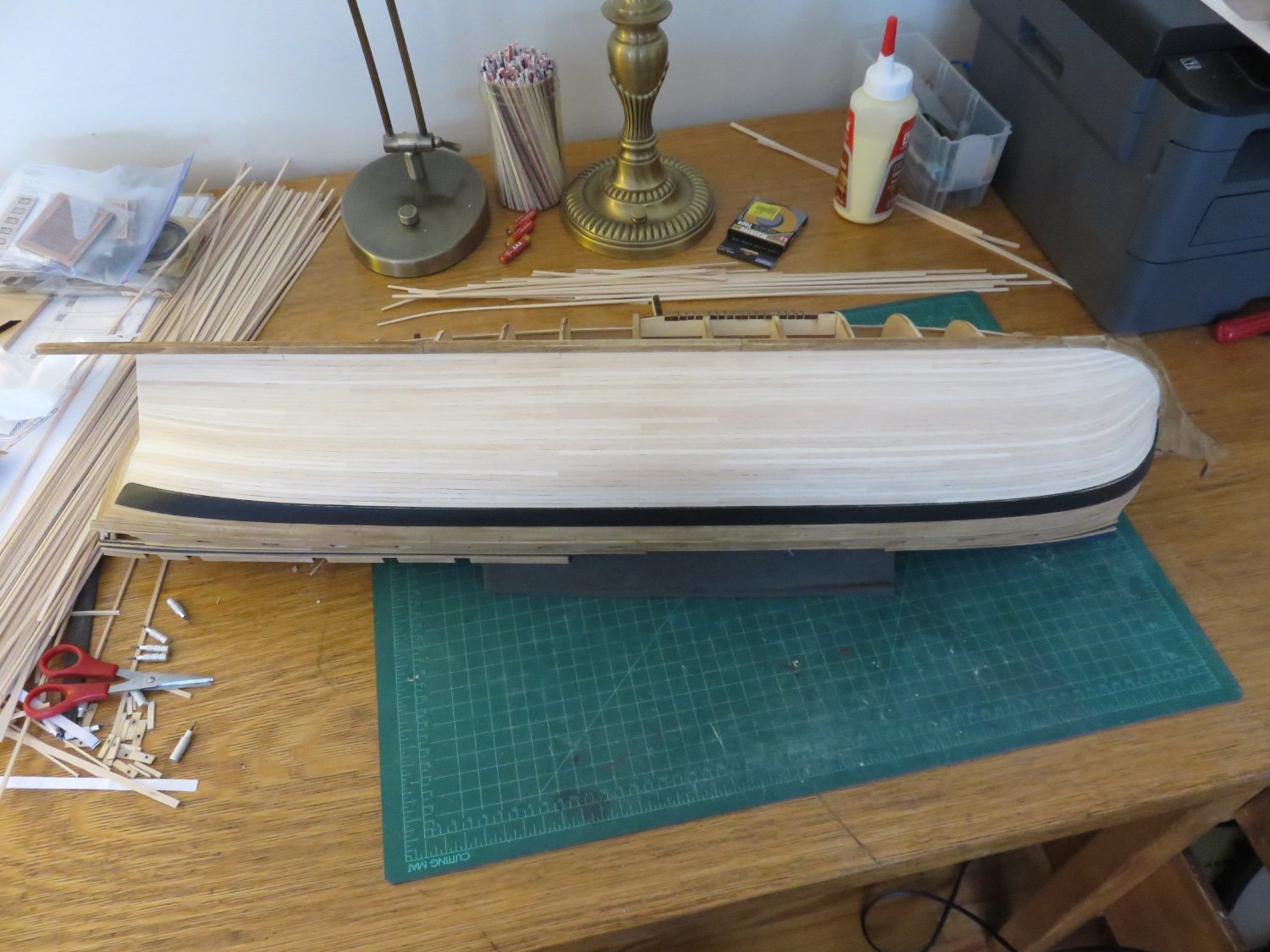
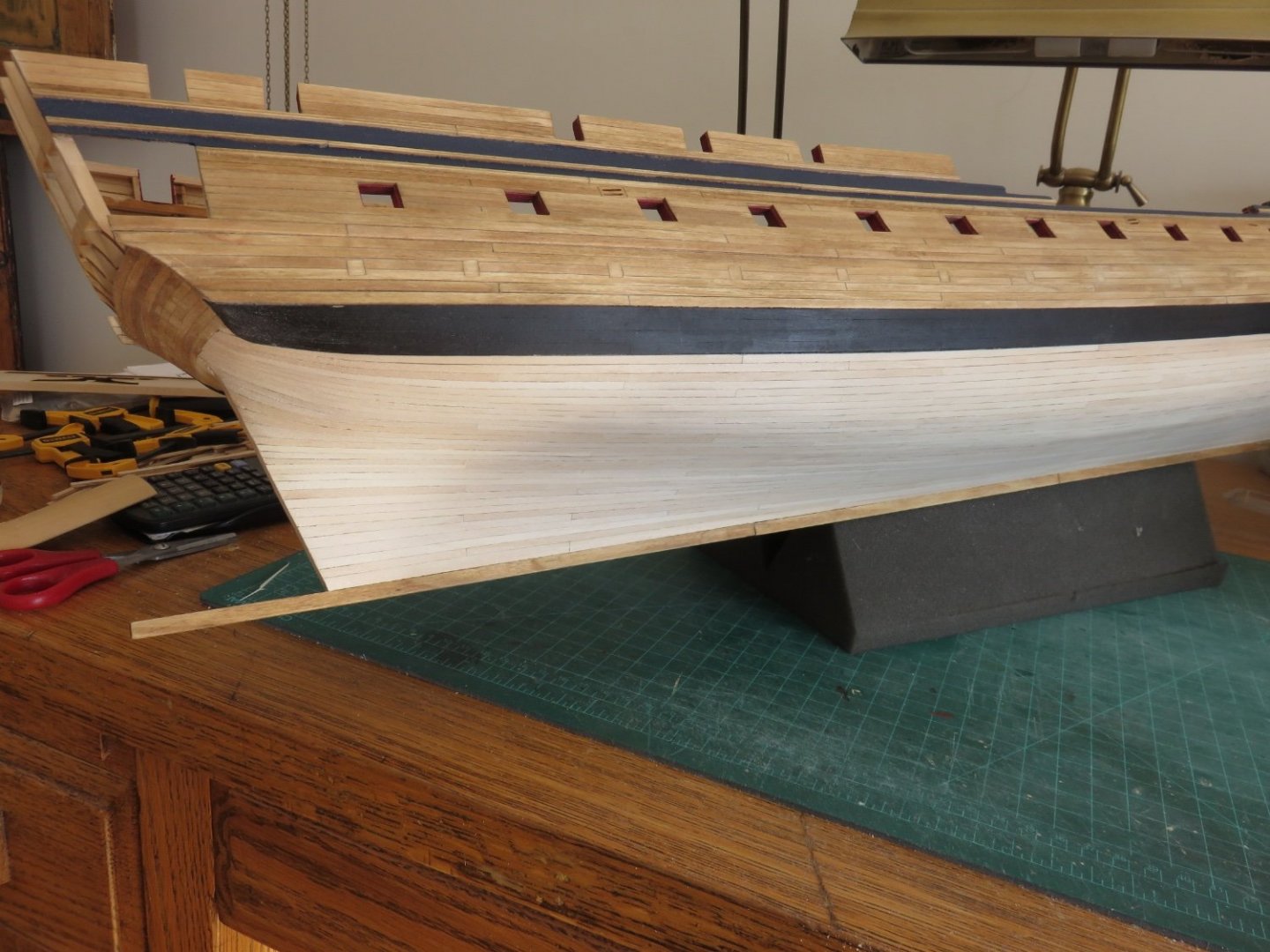
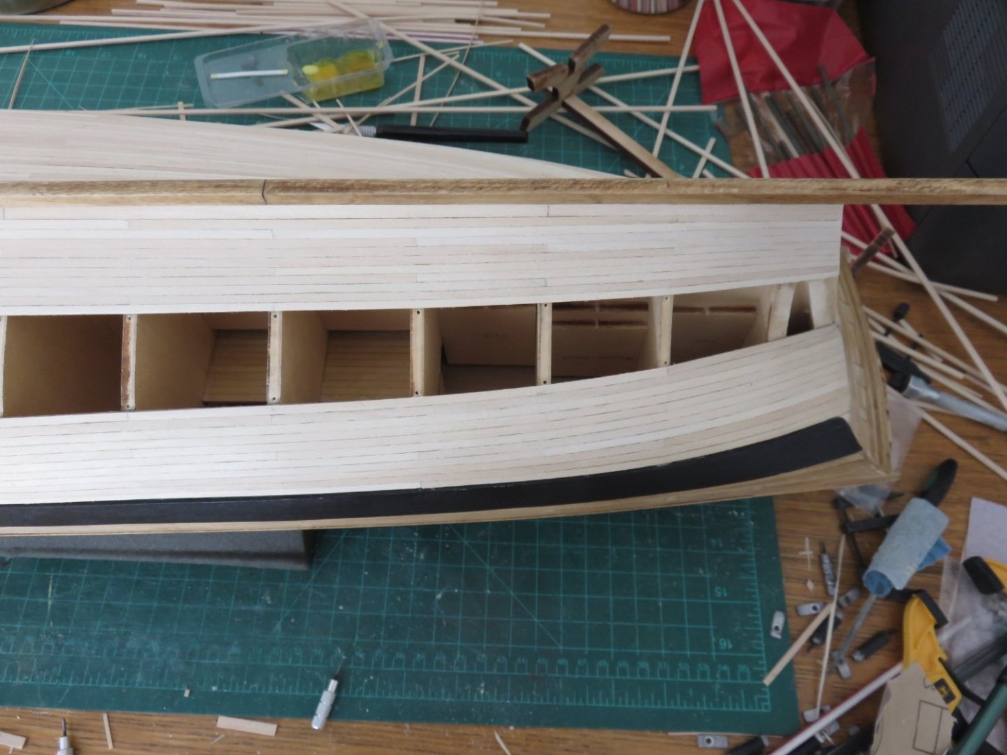
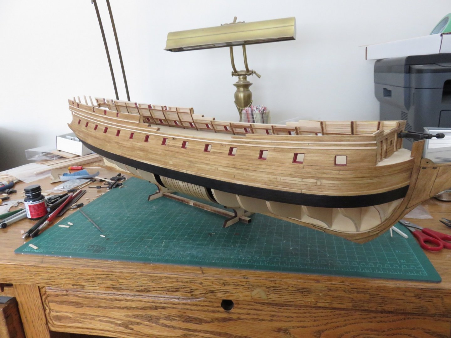
A bit of an update to share on an otherwise grey Sunday morning (at least where I am). I have managed to finish the planking on the port side yesterday. I think I've managed fairly well with it. By no means is it perfect, but I'm happy with the overall result. I've given it a cursory sanding, there are a few spots that still require a little more work (nothing major), but I will get them after I've finished the starboard side. Andy

-
Even diesel boats today still have a small steam boiler. Either a small oil fired unit or an exhaust gas economizer (waste heat recovery), and very often both. Although not used for propulsion, the steam would be used to heat fuel oil (IFO is thick as molasses at room temperature, HFO even thicker), for warming the engine (via heat exchangers) prior to starting, and other auxiliary uses (hot water for the crew). The boiler(s) would require it’s own feed water tank as there are various caustic chemicals needed to prevent corrosion and sediment build up, that you don’t want in general circulation. Andy
- 79 replies
-
- 4
-
-
- SD 14
- Marcle Models
- (and 1 more)
-
You can rule off the blank decal sheet and the transfer sheet with a pencil and by lining up your pencil lines (which should be easier to see) you should be able to get nice straight words. The pencil on the decal sheet can be erased carefully afterwards. Although I’ve never built one before, I’ve seen a few examples on builders models. They always seem to use brass code 100 track (about twice the size of code 55) on models that are about 3/4 the size of yours and it looks hideously clunky. Looking at prototype photos, the structure of the crane looks reasonably straight forward, a frame of rectangular steel tubing and three legs on each side. You probably wouldn’t go too wrong using dimensional styrene stock to make the frame. You could probably pick up some cheap N-scale plastic wheel sets that you can use (if you want a real challenge, make it so it can roll up and down the deck!) Andy
-
Do you have any blank decal paper? I find it easier to apply the letters on a flat surface, then seal them with Testors glosscote or dullcote. All that remains is to apply them as you would any decal. Incidentally, if you’re looking for hatch crane track, try Micro Engineering’s code 55 flex track. Andy
-
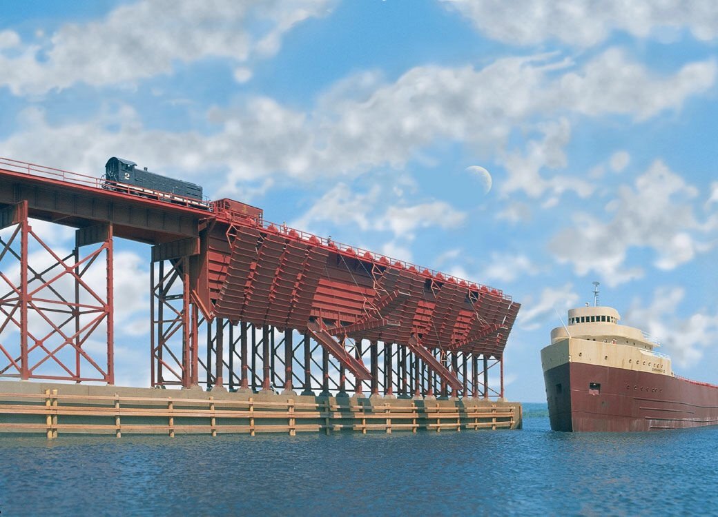
Something to ponder: https://www.walthers.com/ore-dock-kit-48-1-2-x-5-quot-121-2-x-12-5cm Andy
- 72 replies
-
- 10
-
-
Thanks everyone for the kind comments and “likes”! BE and BW, I’m glad you guys also like the blue. I was a bit worried at first that it may prove to be a somewhat controversial colour choice, but I’m pleased with all the positive responses. Andy
-
You’d think that, but the photos that failed were slightly smaller in file size than the ones that did. Andy
-
Still having some issues uploading photos, (same error message keeps popping up... frustrating), but I've managed to get two pics uploaded today. Before Christmas, I wanted to post an update as I had completed the first belt of planking on the port side. After a little debate with myself whether or not to start the first belt on the starboard side (and a pause for Christmas), I'm still not sure what I want to do with the reveal on the starboard side, so in the spirit of giving myself more time to think about it (aka procrastination), I have now completed the second belt on the port side. As it is now, I'm going to finish off the port side planking before returning to the starboard side. I'm managing between two and three strakes a day (provided I've made enough pre-spiled ones for the bow). Slow but steady work. Wishing everyone a Happy New Year, and a safe and prosperous 2022. Andy

-
Thanks Peter! It’s great to hear from you too! The only thing I can attribute the large hole for the quarter galleries, is simply the way Chuck designed the kit. Looking at finished photos of other builds and the prototype, it doesn’t seem to cause too many visual issues as far as I can tell. I’m sure if someone felt like it, they could frame in a smaller doorway if they so chose. When I finally get there, if I feel it looks a bit odd, then I’ll go with my usual trick of fogging the inside of the window “glass” with a bit of dullcote. (Lets light through, but no peaking!) It does make me wonder, though, if the outermost lights on the stern should be blacked out, as opposed to clear glass…. All things to think about. Andy
-
Thanks everyone for the likes and comments! Definitely that was the idea. I've looked through many logs, and everyone seemed to be doing largely the same thing. I want mine to stand out a little bit. At least until some future Confederacy builder decides to copy me, (which I don't mind at all), at least I will be able say I was the first, but for now I'm the "only". Thanks David, I'm doing my best. The Confederacy is a particularly graceful subject. The more I'm planking, the more her lines really start to show through. Thanks Ben, it's been a while. I needed to get myself back in the right headspace, not just for ship building, but logging it too. I think my passenger car blog (down in the shore leave section) helped quite a bit in that regard. Well, I wanted to post a bit of an update, but when I went to upload an image, it came back with an error and "upload failed". I guess I shall have to wait until things get sorted out... hopefully soon. Andy
-
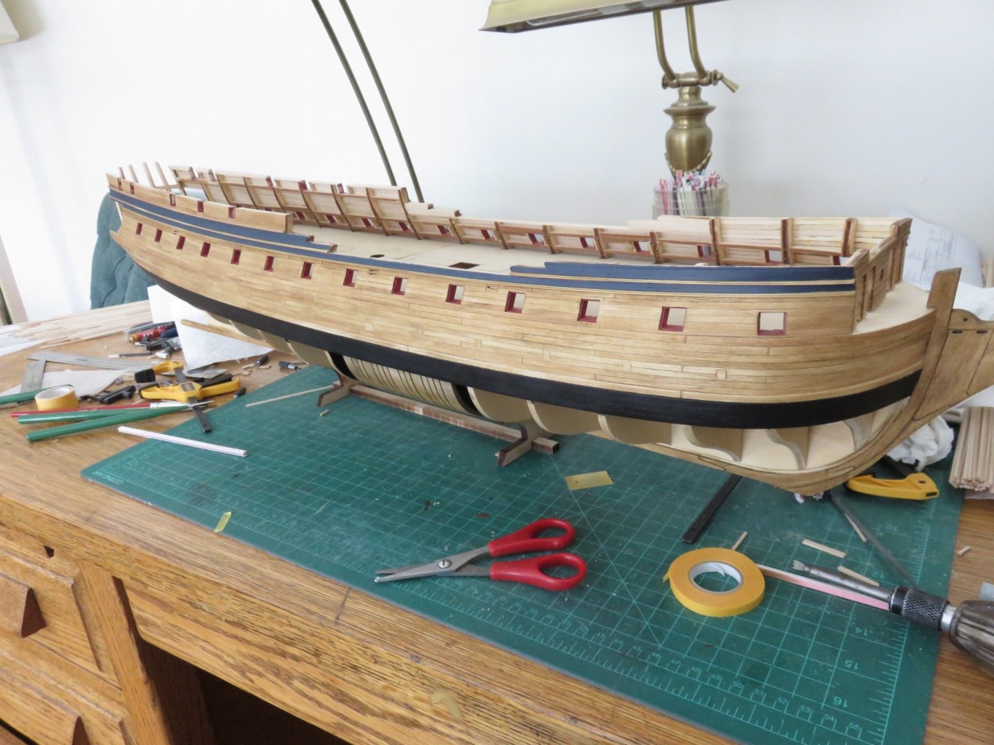
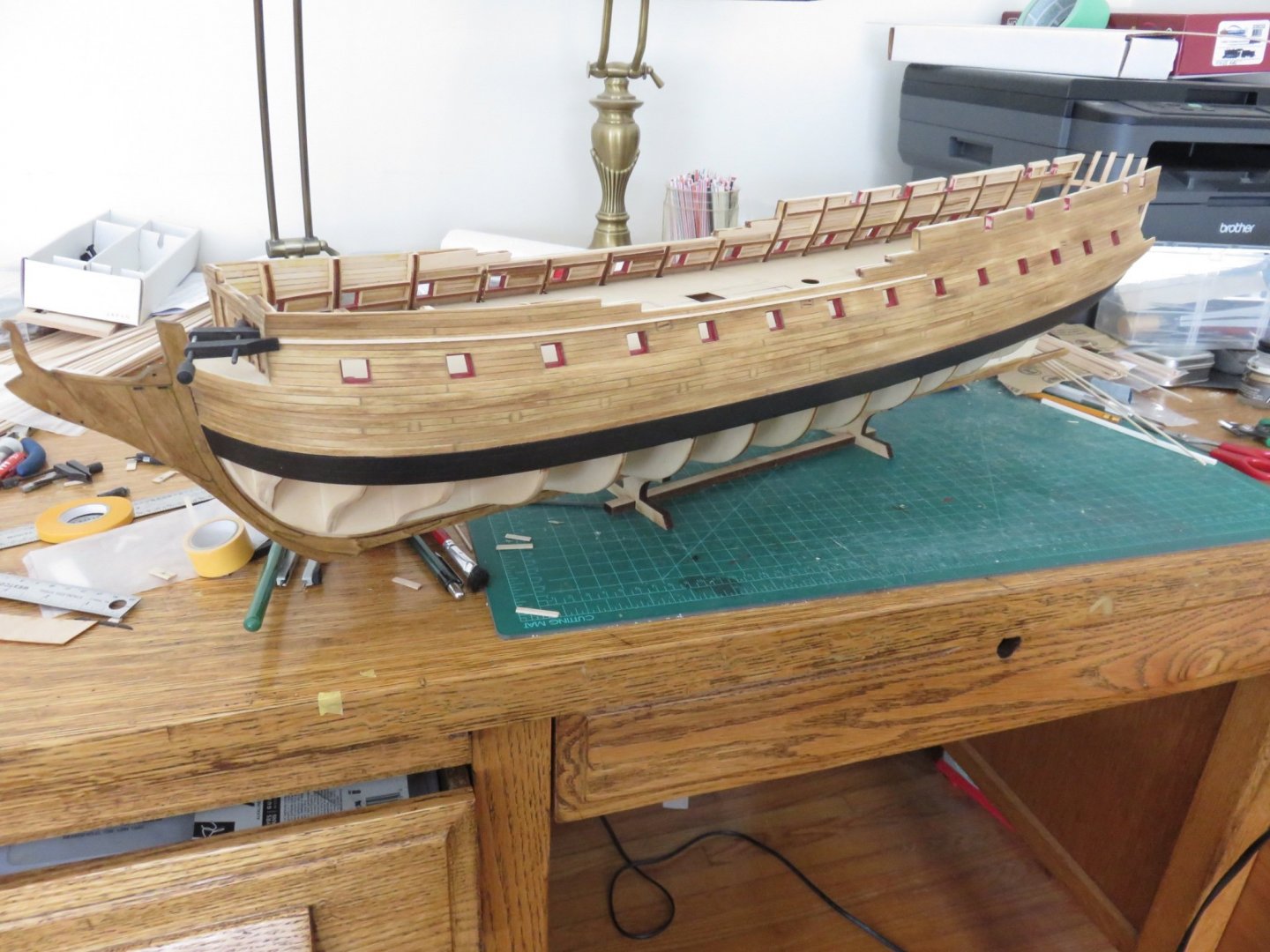
Thanks everyone for the likes and comments! I've had a browse through your log. Your build is looking pretty good too. Best of luck with the planking! That's about all anyone can do, really. I guess I got lucky, she didn't try to eat any of the pieces (unlike poor BE with his Sphynx...) A small update to share. I've decided to deviate a little with the colour scheme. This goes against what I've read about the prototype's possible colour scheme (hopefully I don't get sent to boat-jail for blasphemy🤞). I've gone with a dark blue for the area of the hull between the mouldings: The official name of the colour is Polyscale "C&O Enchantment Blue". I think it compliments well with both the Golden Oak stain as well as the red from the gun ports; Polyscale "NYC Pacemaker Red" (I know, I'm using "railway" colours, but they're what I have on hand). I had thought to return to black for the QD bulwarks, but I've since decided against that, and I think I will leave them as is. I think the black would have muted the dark blue too much. On to paint the port side. Andy
-
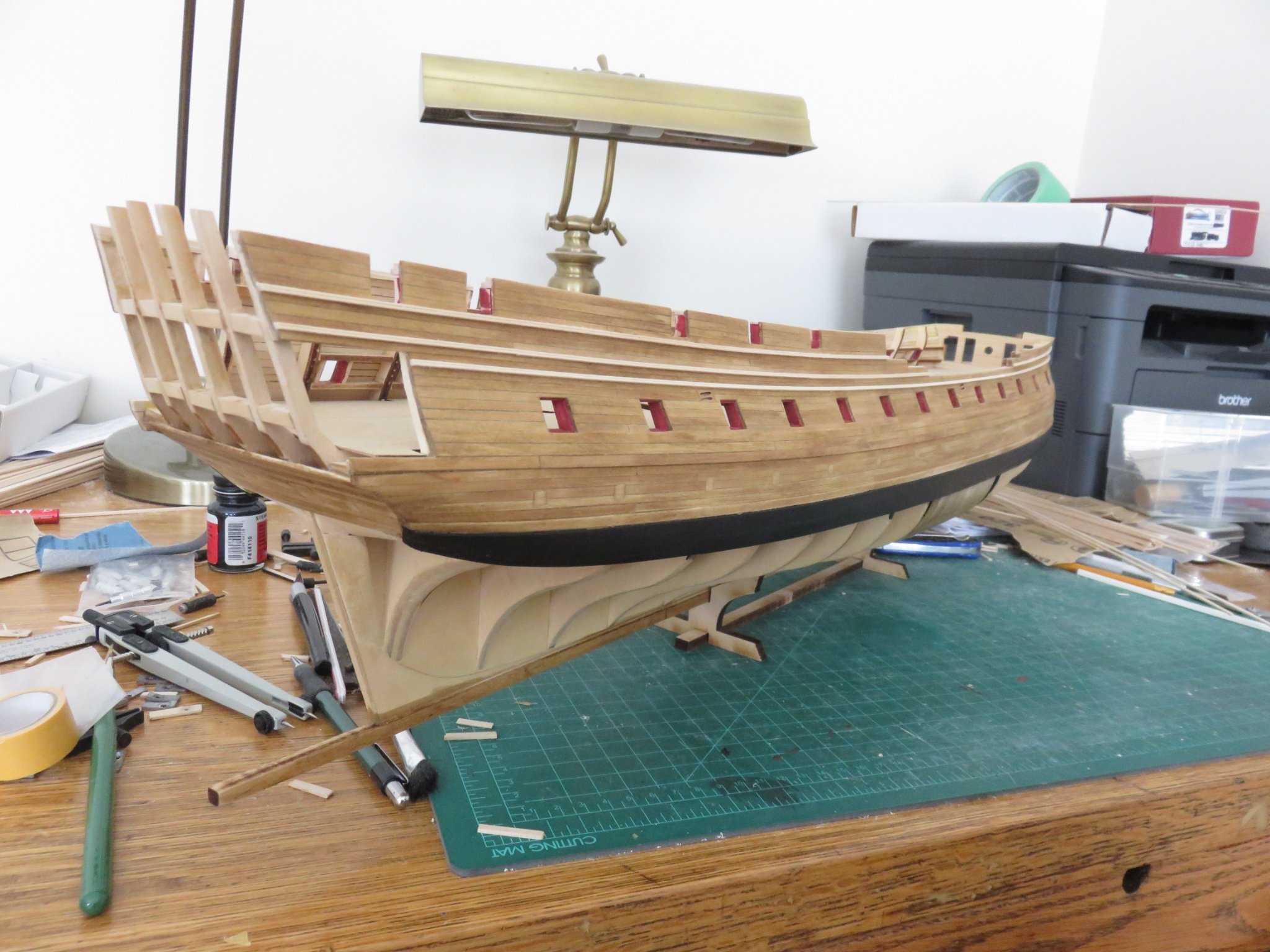
I can't quite remember when exactly I bought this Confederacy kit, probably sometime around 2012 or 2013. It sat for a long time in the closet, virtually untouched, except for the manual. I think I may have the most well read manual out there, (With tongue firmly planted in cheek; I think MS could do a little better job on the binding, it wasn't really designed to stand up to the rigours of repeated readings 🤪). I finally started started picking away at this build some four or five years ago, between other projects. Progress has been largely sporadic, with more than a few backwards steps being taken. On many occasions the self-critic took over and the kit was shelved for months (or most recently for almost two years). For many reasons (of which, the above is just one), I've avoided a build log until now. I'm at a point where I'm satisfied with my progress so far, and I hope that the worst of the back stepping is now over. I have completed the planking from the wales upwards and I'm now in the process of adding the first beaded moulding strips. The starboard side mouldings have been added, and the port side is in progress. If things look a little wonky with the stern light window frames (cills and lintels), it was due to an unfortunate incident involving the large nose of a curious young german shepherd, that decided to investigate the stern, while work was being done on the other end of the ship. The interloping nose went undetected until the work required a shift in position... I'll leave the rest up to your imaginations.. but suffice it to say, it wasn't pretty. Pieces where quickly gathered up, and splintered wood glued back together. Before the time comes to attach the transom, everything will be revisited and correctly re-aligned. I've used Minwax Golden Oak stain for the planking above the wale, with some Polyscale acrylics that I had kicking around, for the black wale and the red gun ports. Andy
-
If I may suggest, when building with styrene, consider building in layers. Start with a 0.010” or 0.015” outer layer, and work inwards. The thinner stock will make cutting easier and more accurate, the subsequent heavier layers only require more general window openings. Have a look to see how I built my CPR coach: Andy
-
Most of the ore I’ve seen heading up the lakes out of Port Cartier, Pointe Noire and Sept Iles was pellets. Those mines also ship concentrate ore, but mostly for overseas markets. The concentrate ore can be finicky for SULs, depending on moisture content, but I did get out to the CSL Spirit, when it was involved in the transshipment operation out of Pt Noire, and it seemed to run alright through the gear, no hang ups and not much mess in the tunnel. Algoma holds pretty tight to their contract with Dofasco, who still have cranes at Hamilton, so for them SUL equipment isn’t entirely critical. I wonder if the yard they signed with initially in China hadn’t run into financial difficulties if we’d be seeing more Equinox 740’ SULs by now. Andy
-
Bulkers need bigger hatches (hence fewer) in order to accommodate shore unloading equipment, as opposed to SULs. If you look at the CSL St. Laurent or the CSL Welland, you’ll see a similar number of hatches to the Equinoxes. Sadly I’m not on any ships anymore (except as a passenger), was forced to give it up because of my eyesight (more specifically, lack thereof). Andy
-
The Algoma boats use a “Macgregor” style quick acting cleat, along with square section rubber seals (similar in cross section to a 2x4) running in a U channel under the lip of the hatch cover. These seals mate with a compression bar set on the hatch coaming. Very similar to the arrangement found on deep sea ships with hydraulic hatches. This allows for fewer clamps per hatch cover (labour saving!), but does require a more rigid structure. All the CSL new builds retained the now 70 year old system of Kestner clamps and small seals on the hatches. The seals are simply a 3/4” wide by 1” deep strip of rubber, keyhole shaped in cross section, held in a narrow groove in the underside of the hatch cover, these seals mate only to the flat top of the hatch coaming. This system is structurally lighter, and allows for more flexing, but requires more clamps per hatch (about 33% more), hence more labour intensive. In the current corporate drive to control costs (read cut crews), I can’t, for the life of me, figure out why CSL didn’t really do any (major) innovation on the deck arrangement on their ships. Technically, they are well designed ships, efficient engines and cargo handling equipment, but they’re trying to run a 70 year old style deck with less than 25% of the crew (as compared to when the Kestner clamp was the latest and greatest….. circa 1947). Andy
-
I consider the Lanz bulldog and the British made Field-Marshall "honorary steam tractors". They're also great "party trick" tractors, the Lanz because it can run without the single cylinder engine completing a full revolution, and the Field-Marshall because of the unique method used to start the engine. And just for good measure, some steam: Andy
-
As near as I can determine... Left to right: J.I. Case model LA (1940-1953) or model 500 (1953-1956) IH model 650 (1956-1958) IH-McCormick Super W6 (1952-1954) Allis-Chalmers styled WC (1938-1948) Massey-Harris possibly model 44 (1947-1953) Andy