realworkingsailor
-
Posts
3,274 -
Joined
-
Last visited
Content Type
Profiles
Forums
Gallery
Events
Everything posted by realworkingsailor
-
 I’ve finally just figured it out! Haha! The key hint I was missing, both of those fittings are located directly below the astro-dome. When the navigator needed to take a sight, those panels would be swung up and clipped together. They would help him steady himself while taking a sextant sight. Item #91 in this detailed drawing Incidentally, it also explains those box things located in the bomb bay. Apparently they’re an inflatable floatation system, to be used in the event of a water landing. I need to spend a couple of hours studying this drawing…. Andy
 -
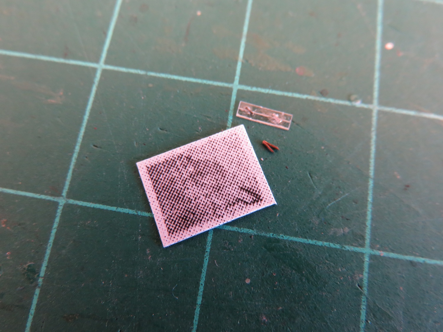
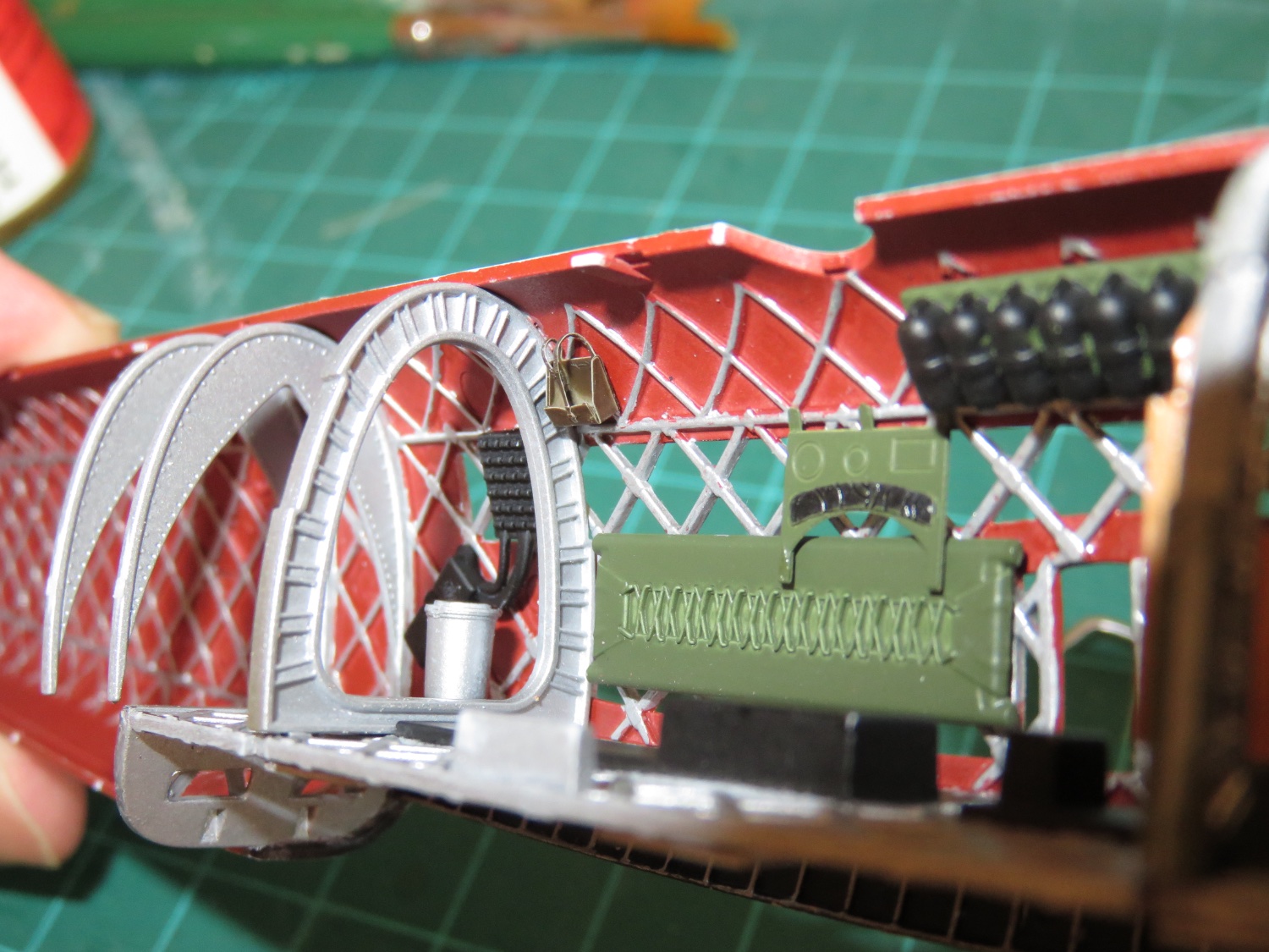
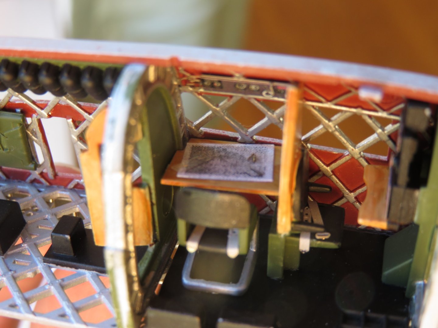
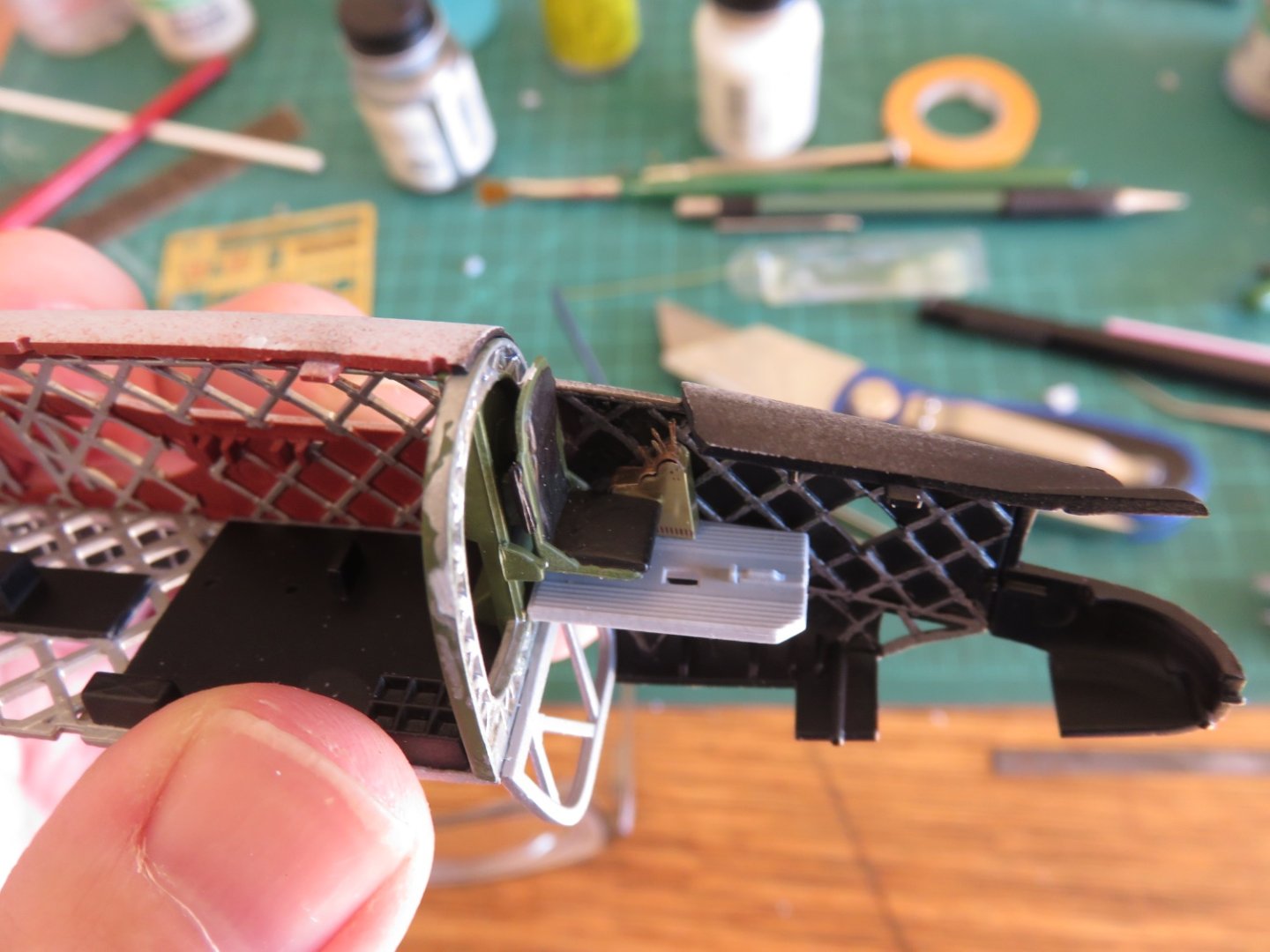
So this has been a fun little diversion project... A chart, some parallel rulers and a little set of dividers. The ruler I made out of some thin clear styrene stock, I used some tiny pieces of stainless steel fret from one of the Eduard PE sets to simulate the links (these things are microscopically tiny). I did stick them on with a minute drop of canopy glue, but it still left a little smudge on the plastic, unfortunately. The dividers were made from a leftover lever, from the PE control console, folded over on itself. I gave the chart a quick shot of dulcote before I glued it in place on the chart table. The navigator is starting to look like he's actually doing his job, and not just staring out his perspex bubble! I also took a cue from that earlier interior photo to add an extra bit of detail: Just in the corner above the stretcher there is some sort of storage case. The PE set indicates there are supposed to be a couple located just inside the entryway (beside the bomb aimer), but curiously supplies a couple extras. One of them has now found a home. I wonder if I could manage those curtains too....🤔 Andy


- 174 replies
-
- 10
-

-

-
I misspoke in my above post, I meant to say I was going to use the chart on the left (since corrected). Now it seems I have an obligation to do so! 😁 Andy
-
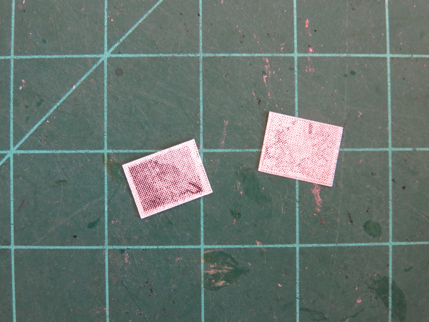
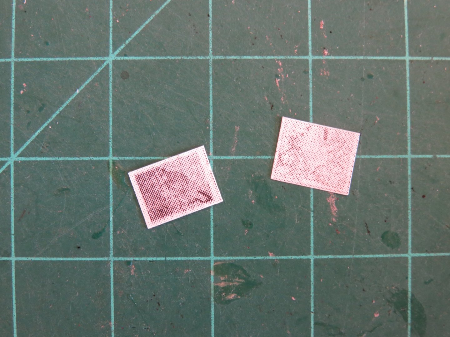
Thank you for your kind compliments! I have to give Airfix credit in the design of this kit, they've really done a great job. I think over the passage of time, when people think of the air war over Europe, the Wellington bomber has become overshadowed by its larger, more popular cousins, the Lancaster and the ubiquitous B-17. As I mentioned last evening, I found a good source of Hi-Res aeronautical charts, out of the extensive collection, I settled on two possible examples: Unfortunately, I am constrained by the resolution of my printer, but I think they will suit my purposes. I printed the charts from full resolution, scaled down to 5%. On the left is supposed to be the aeronautical chart of England North East dating from 1941 and on the right is a plotting chart covering Cork to Stettin dated July 1942. You can sort of vaguely make out the charts. I have room on the chart table for only one chart, so I may use the one on the *left*, as there is a bit of contrast and a more defined shape of "something". I may now have to make up some instruments for the navigator, a set of dividers and parallel rulers... Andy
-
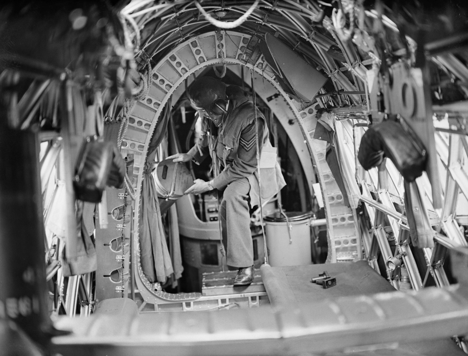
Here’s the interior photo again (from Wikipedia): There’s a wealth of details to take in, including the black lid on the…. Seat… (subsequently corrected on my model!). Andy

-
Well, that was easy! Found a great online resource for WWII vintage aeronautical charts in my own backyard. McMaster University, in conjunction with the Canadian Warplane Heritage Museum has a fully digitized online archive, free to download, in high resolution. It’s a pretty impressive collection: http://digitalarchive.mcmaster.ca/islandora/object/macrepo%3A75555 Andy
-
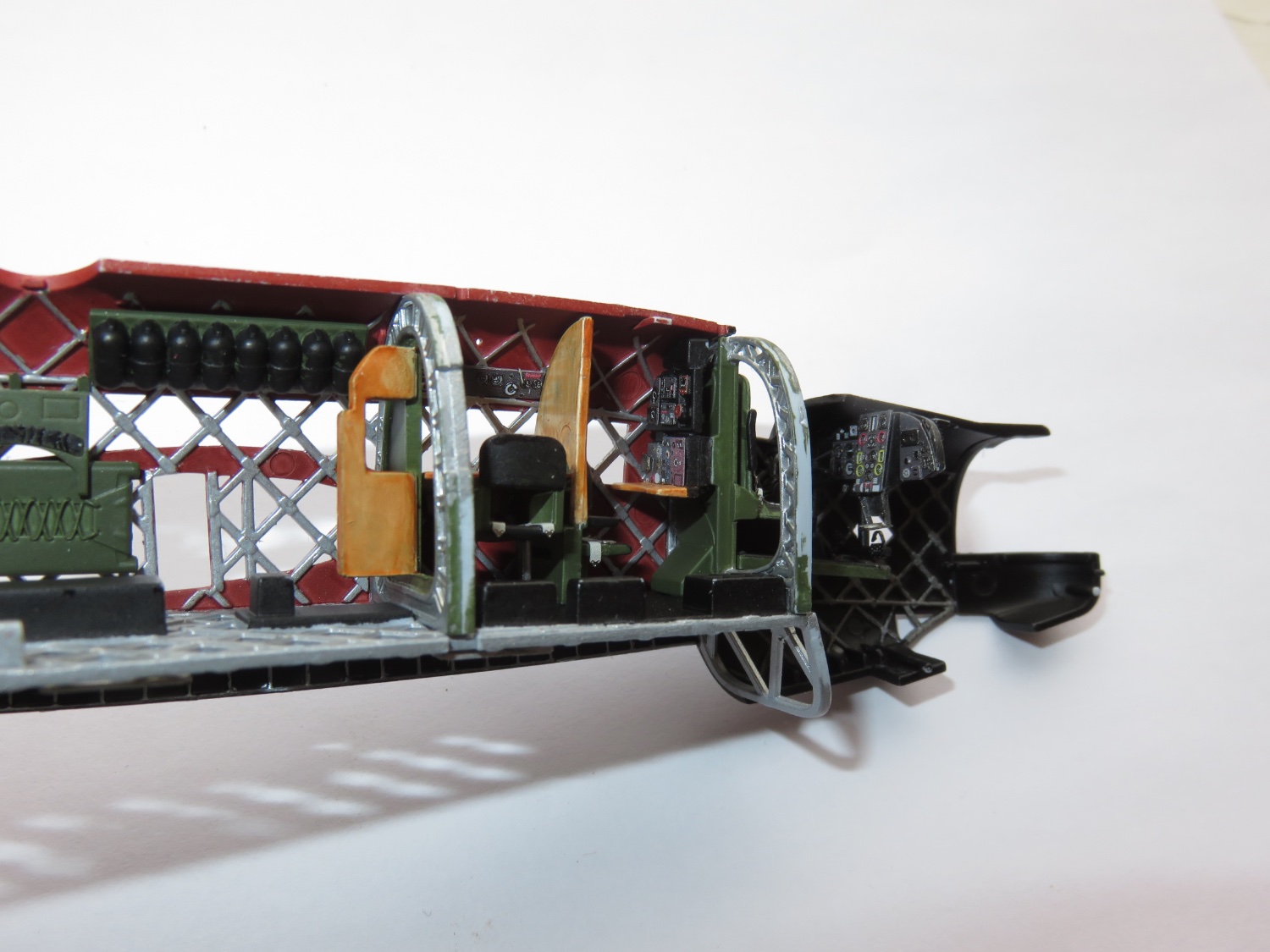
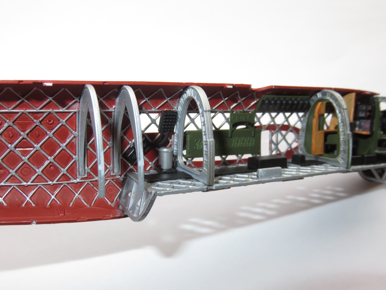
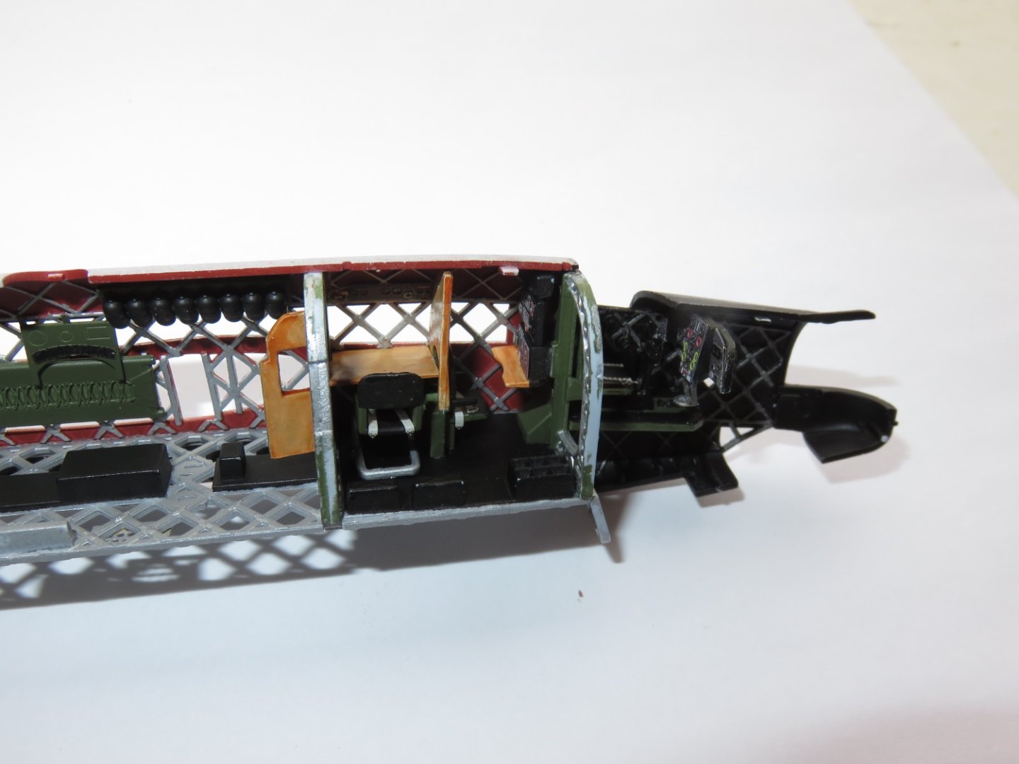
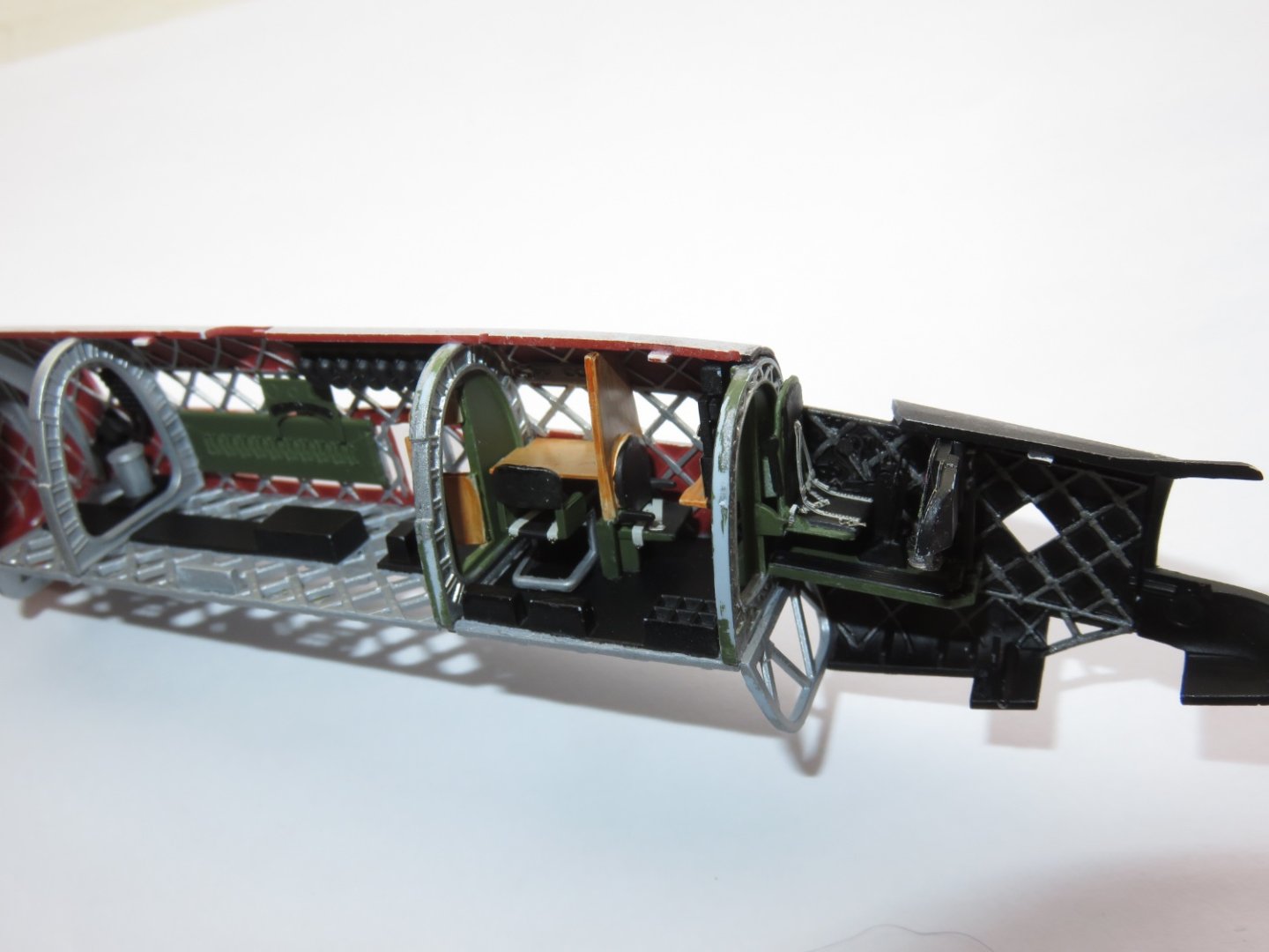
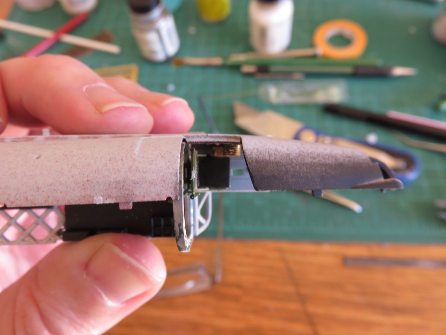
Thanks everyone for the kind comments and "likes"! More forward progress has been made, and some larger assembly has begun. It's starting to look like something!. I first finished picking out the aluminium frames in the fuselage half, and the interior is now being installed. Looking at the aft end of the bomb bay, I'm pretty sure the large silver "can" is the airborne seat of ease (to use the local parlance). There's a flare chute that goes on the other half of the fuselage, which leaves only one other real possibility. I can't help but wonder, given its location over the bomb bay, that some crews didn't feel the urge to add a little something special to their deliveries. Something I've never seen spoken of. Just forward of the bulkhead was a cot/stretcher. Airfix must have chosen to model this in the stowed position, as any contemporary photo's show it laying flat, ready for use. Just above the stretcher is another small piece of PE, a device I am wracking my brains trying to figure out. I have found only one photo online showing that particular object, and it seems to be simply a board with a vinyl/leather bolster draped from it (the black crescent shaped object). Finally, just aft the bulkhead with the open door, are some oxygen bottles. Moving along, the first position forward of the bulkhead is the navigator's station. Not much there, just what I am assuming are flight information readouts (heading, altitude, airspeed) above the window, along with a nice plotting table and chair. The seatbelts for this station were very easy to figure out! I am thinking about trying to find an aerial chart online that I could print out and stick on the table. One more view of the work to date, for good measure. There are a couple more components yet to be added to this side of the fuselage, before shifting my attention to the other side, (a lot more PE on the other side) and getting things closed up. Andy


- 174 replies
-
- 11
-
-
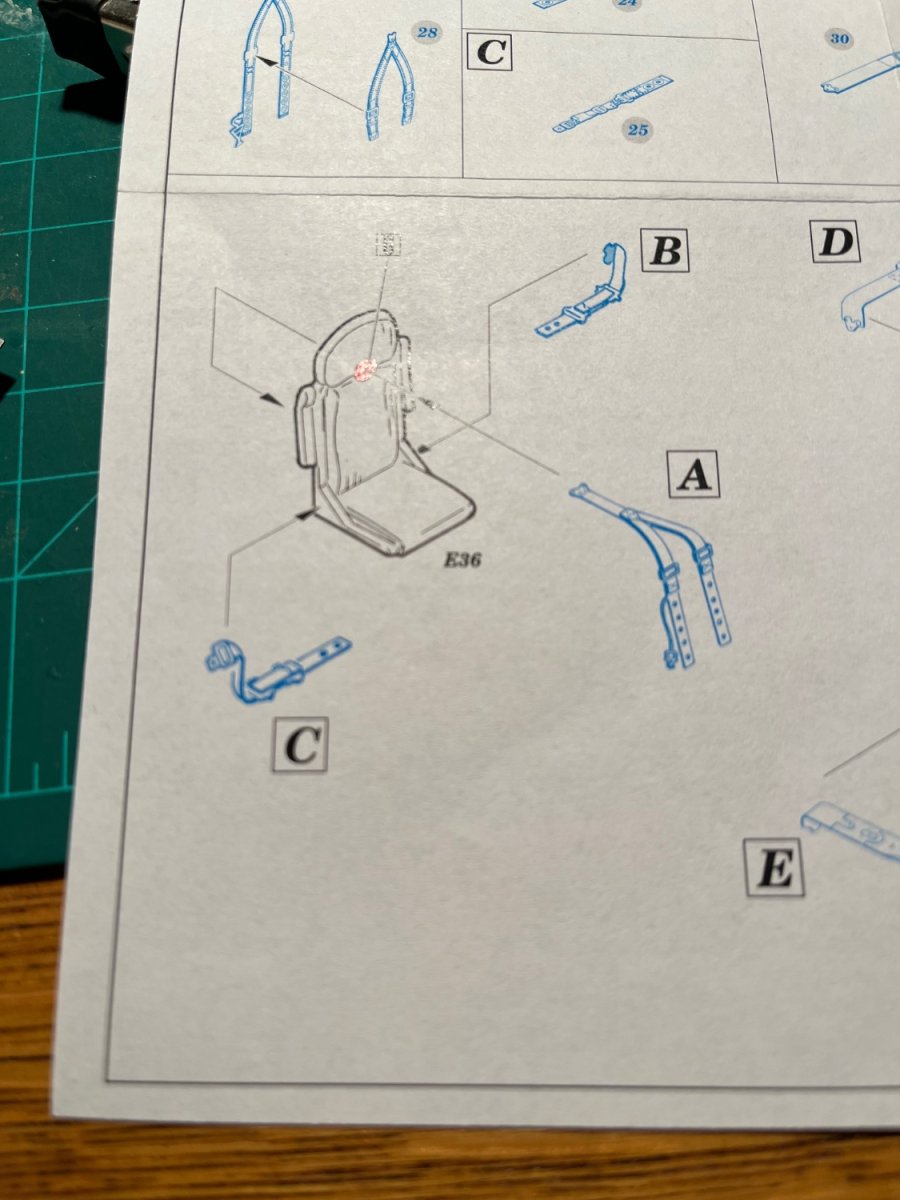
The shoulder harness is straight forward. The lap belt…. ??? 🤔 I’ve tried looking online at photos of the prototype cockpit, can’t even find a seatbelt… Andy

-
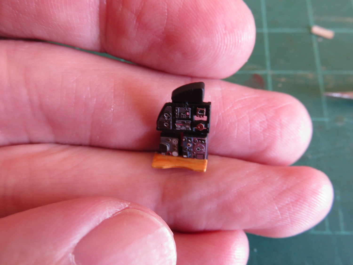
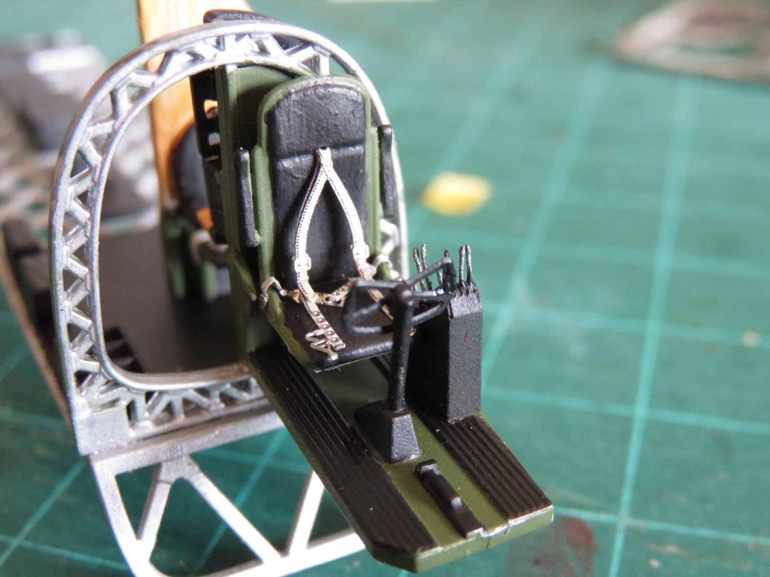
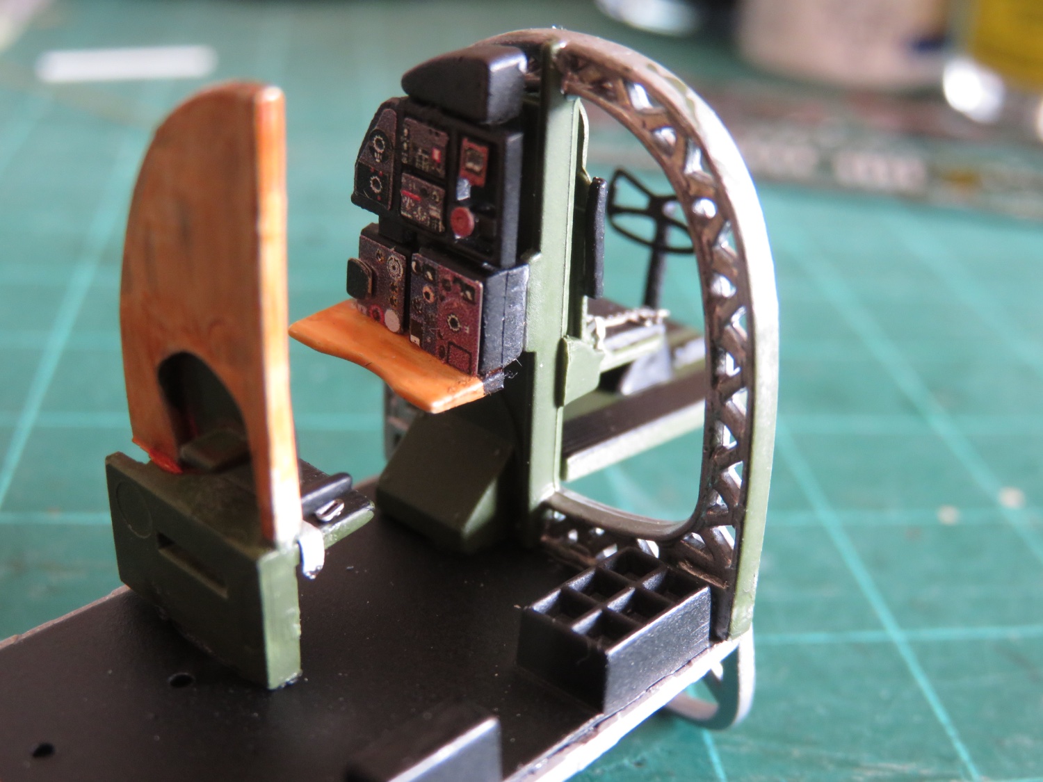
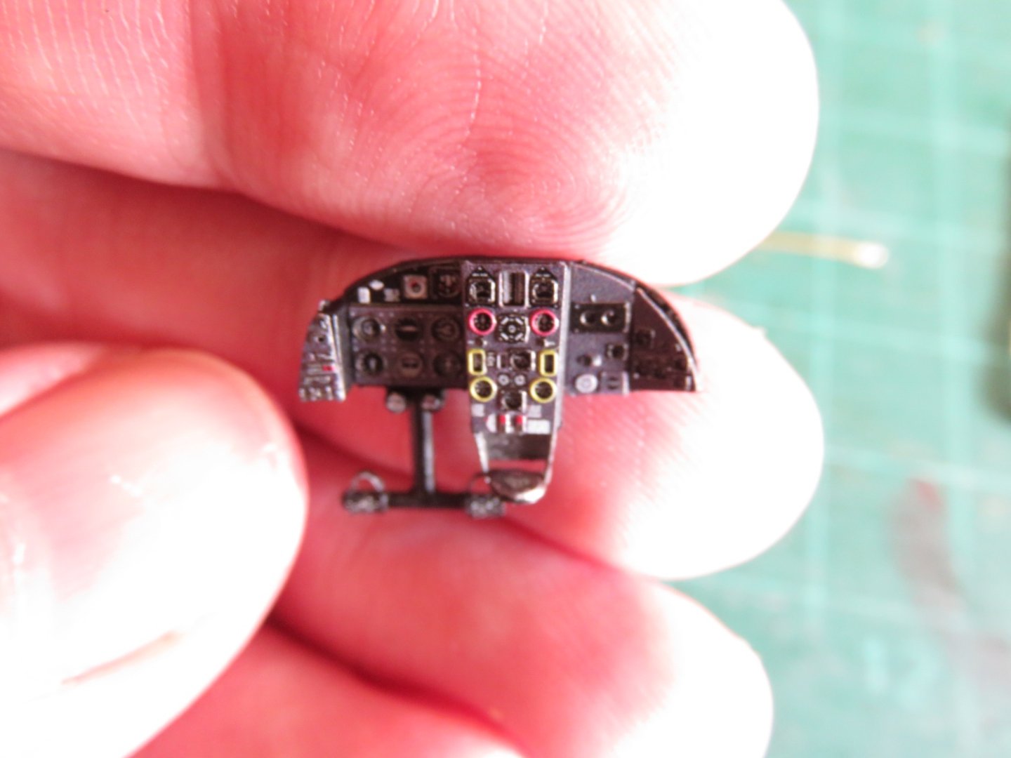
Thanks everyone for the comments and the likes, they're always greatly appreciated! @Rick01 Which Wellington is that? The poor thing looks quite stripped down, is it being restored? (Fully or partially?) @Egilman LOL I would hesitate to call myself one of the "1/72nd guys"...yet! I have some experience in 1/87th as far as model trains go, but nothing quite as finely detailed as this. Aside from ship models, most of my PE experience comes from working with Athabasca Scale Models kits. (Back when they were still in business, some of their stuff can still be found kicking around). They tended to require a little something a little more akin to brute force than finesse! Carrying on with Wimpy, More fine PE detail work, although this is more along the lines of file off the grey plastic blob and add this more detailed face plate. First up, the radio station: Next up the cockpit console: The kit supplies decals for the instrumentation, but this looks way better in my opinion. I like the depth in the individual gauges. Although I don't need this part yet, it's nice to have it finished and ready for installation when the time comes (soon enough). This now officially brings me up to step 8 in the instructions (still one page 1, though). This now means I have the pilot's seat, and some flight controls, as well as the radio operator's station built. Step 9 involves installing what I can only assume is the.... um... "extra functional" seating, above the aft end of the bomb bay decking. I do need to grouse about the Eduard instructions regarding the seat belts, however. Specifically the lap belts for the pilot, it would have been nice to see a picture of how things were supposed to go, rather than some misleading drawing saying to bend the PE in some weird way and attach roughly to this location in some manner that cannot possibly work. Apologies if I have the lap belts incorrect, it's the closest I could figure out. The view looking forward from the radio operator's station: Slowly things are coming together. I'm almost through picking out the aluminium frame on one fuselage half, and after some touch up, more assembly can progress (at least until some more PE induced sidetracking crops up). Andy


- 174 replies
-
- 12
-
-
-
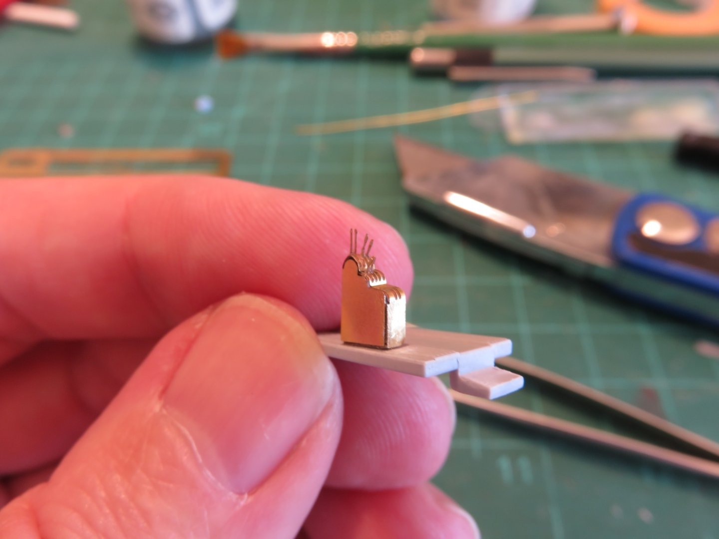
Work is still progressing slowly. Between painting, and picking away at one minute task after another (or more frequently bouncy between one microscopic task and another ignorer to preserve one's sanity). The "fun" thing I'm finding out is how to slot in the various PE detail parts into which step of the instructions, there's a lot of looking ahead (and prefabricating), then returning to the instructions to work out a slightly revised order of operations to ensure things go together smoothly. The latest bits concern the cockpit, specifically the control stand beside the pilot's seat. This wonderfully designed PE torture device replaces a nondescript moulded grey blob cast on the deck. Lots of curves and counter curves to this little lovely. The top piece (where the control levers slot in) comes in two parts; a short forward piece with only one large-ish curve, and the aft piece with a weird wavy profile. Guaranteed the more complex aft one will snap off at the corner seam (the nearest vertical seam visible in the photo above). For anyone else building this kit, I suggest just going ahead and doing this anyway, as it makes bending the top profile easier. I inserted a styrene block inside the stand to provide a better glueing surface (which should be done anyway, even if you do manage this piece of Eduard Origami without breaking anything). Oh yeah, the control levers.... they're small.... very small.... and fiddly.... and annoying... and easily lost/bent/mangled/transferred to another dimension. Six down, four more to go. Thankfully, with many of the smaller parts, Eduard does supply SOME extras. Another little surprise to watch out for, the new control stand is larger than the grey blob. In order for things to fit, a portion of the pilot's seat needs to be filed off. You can kinda see here: And somewhat here: Thankfully, it should all be well hidden, and not noticeable. Most components are still only dry fit for testing/demonstration purposes. Still so much yet to do and paint, before any large assembly can take place. When my eyes are too strained from microscopic PE parts, I will indulge with some more eye strain inducing detail painting. Picking out the aluminium frames in an appropriate colour paint. I find this can only be done in 15 to 20 minute intervals, as once the paint on the brush starts to get a little clumpy, it's best to stop before making too much of a mess. As it is, I will still have to go back and touch up some spots with the base colours. The Silver is Floquil Old Silver, which isn't too bad a match for the Tamiya Aluminium. In the forward area, I opted for Humbrol's Gunmetal colour, for something more subdued in keeping with the black, but maintaining a little metallic shine. Over all, I'm still having fun with this build. It is definitely a challenge, but not impossible. Andy
- 174 replies
-
- 13
-
-
-
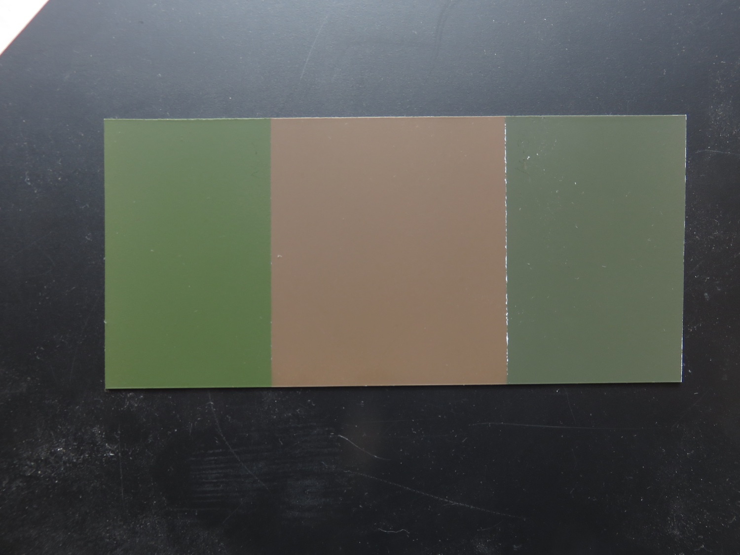
Thanks for the input! I actually agree and had already decided to go with the darker green on the right. For what it’s worth, Tamiya labels both paints as RAF dark green, the right one as Dark Green #2 (Tamiya paint code AS-30). Tamiya itself recommends the other shade of green (code AS-9), for their Lancaster model. Trying to hunt down and replicate accurate prototype colours can be challenge. Many colourized photos (which I don’t consider to be an accurate source as far as colours go), show a green more similar to the green on the left (and the brown to be much more of a tan/sandy colour), and contemporary colour photos shouldn’t be trusted, as time can play havoc with colour film, without the ability to ascertain how, in what conditions, the print/negative/slide was stored, and the degree of oxidation/UV degradation. It can be equally hard to tell from modern museum photos due to varying light levels, the age of the paint (and the layers of dust), to say nothing of the odds that the museum itself had the correct colour of paint to begin with (yes, museums do make mistakes). I’ll still use the lighter colour, but it will be relegated to interior details, that won’t be as visible. Andy
-
Hi Kev! Looks great. I had to look online, but yeah, that looks basically like how they were stowed. Have you thought of sourcing some Evergreen “I” beam or “C” channel? If you can find a small enough size, it might give you that fine profile of the racks. Going by this photo here: Otherwise, looks great! Andy
-
My paints finally showed up yesterday! Yay! I had to whip up a test panel as Tamiya's AS line of rattle cans has two options for RAF dark green, and I needed to see which was closer to the Humbrol paint call out, and which one I liked better: I've made my choice (and I won't say which yet), but what does everyone else think? Andy

-
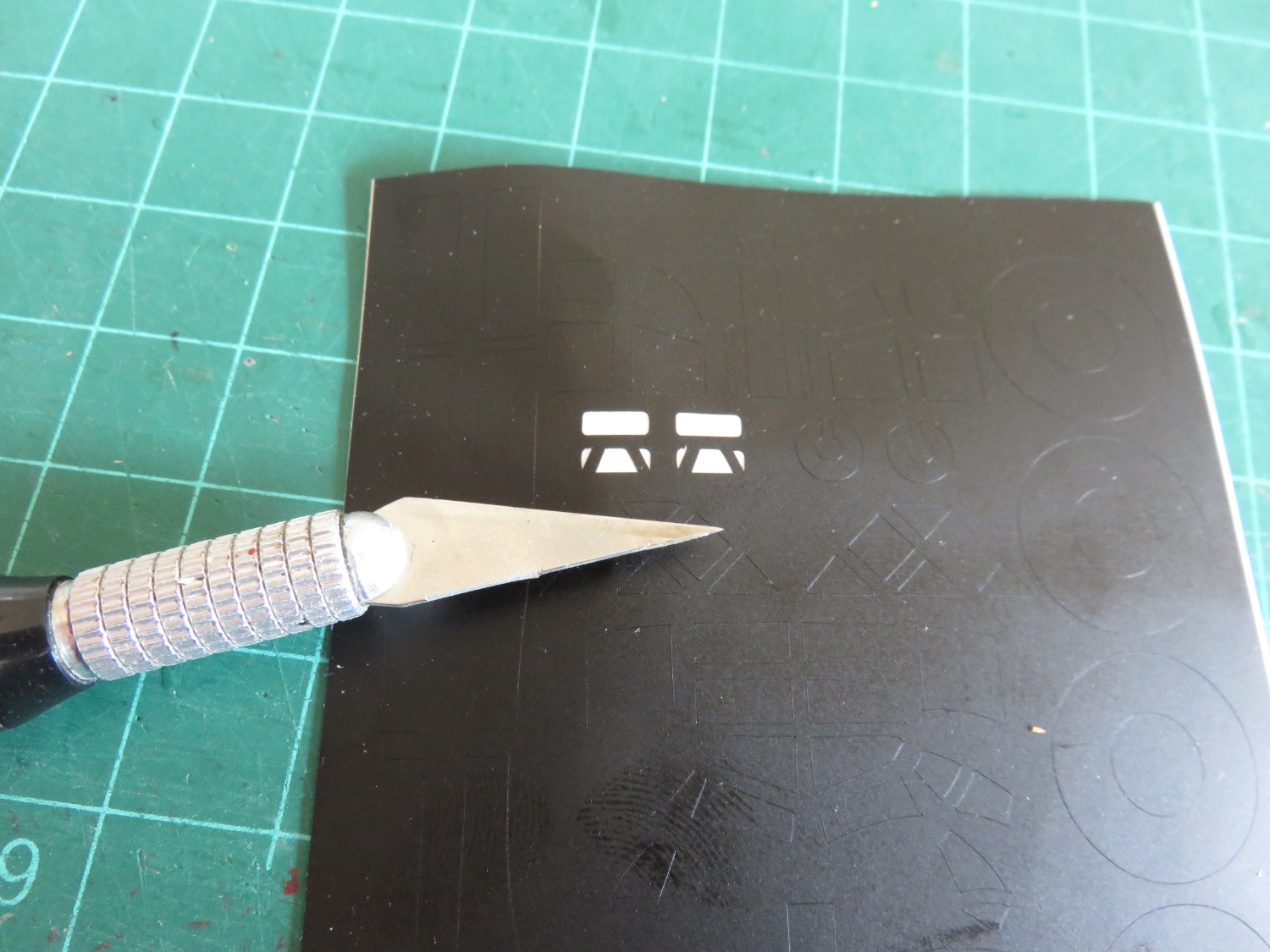
I did some digging, as I remembered I had an old stereoscopic image viewer. Maybe worth a try…. I do cut the PE on the cutting mat with a sharp craft knife, but I do so as close to the fret as possible. The Eduard PE is very thin, 0.010” if I had to guess, so it doesn’t take much pressure to cut. Afterwards I’ll remove the connecting tab with some flush cutting sprue nippers. So far I’ve had no trouble with extra bends (at least, none caused by the cutting out of parts🙄). Andy
-
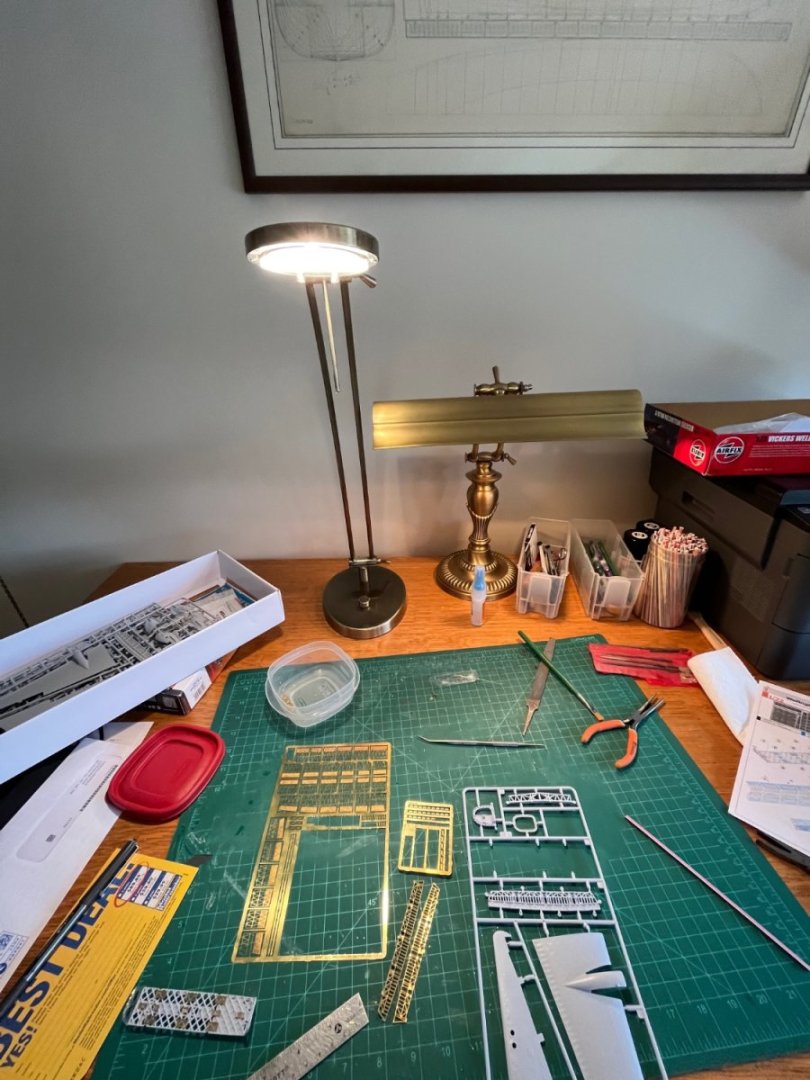
In addition to the normal room light fixtures (and a great, big, huge, south-facing picture window), I have a handy dimmable halogen “reading” light, as well as a banker’s light. The reading light is an excellent spot light, and the banker’s light fills in the shadows from behind. As for a soundtrack, sometimes the TV is on behind me tuned to something mindless (which is pretty much anything and everything that’s on these days), or my stereo. And then every so often, there’s the dog to remind me when it’s snack or walkie time (usually both)… Still need to work on better magnification, my progressives don’t quite deliver as expected! 🤪🤓 Andy
- 174 replies
-
- 12
-
-
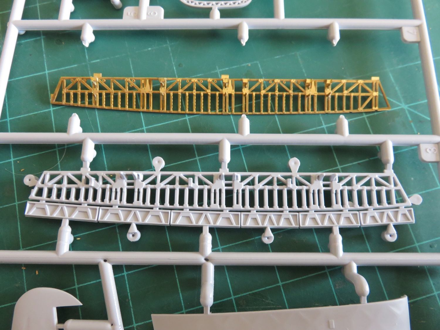
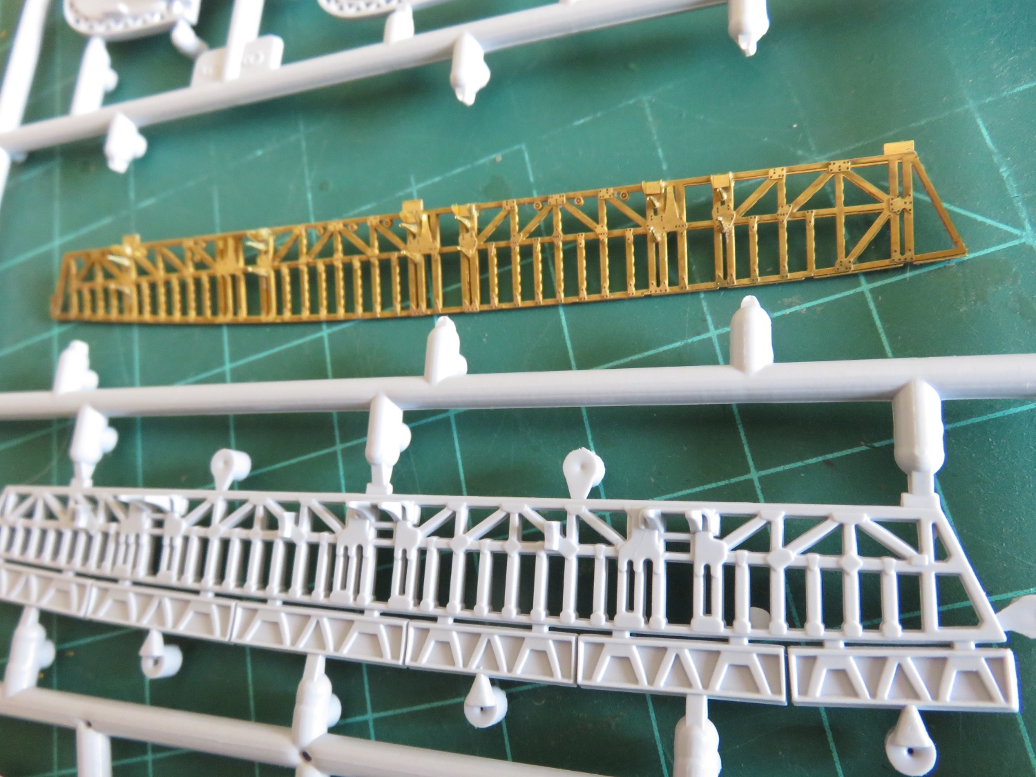
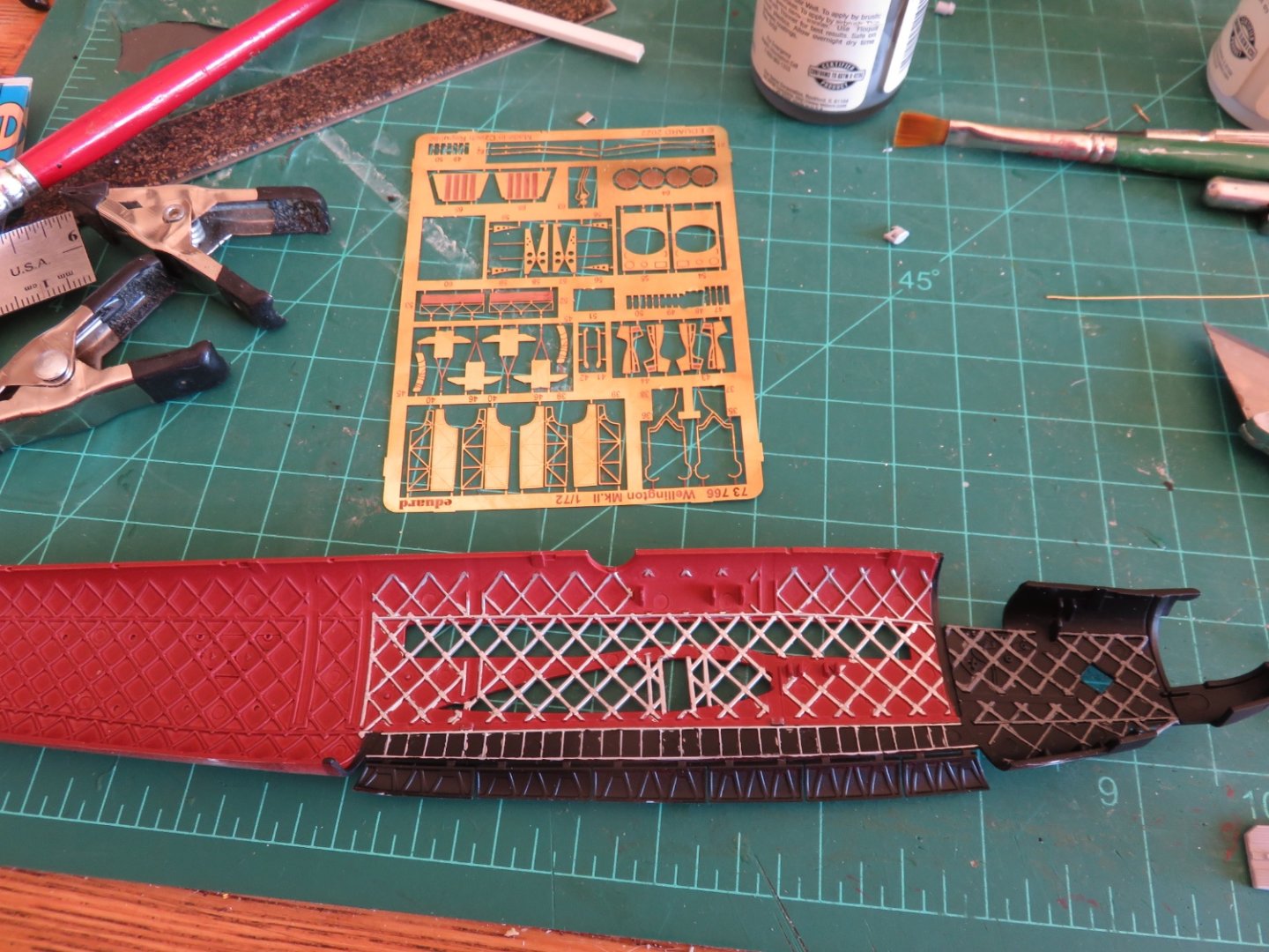
Thanks for all the likes. The beautiful we had weather this past weekend didn't help to much as far as making build progress. Had to get outside and enjoy the sunshine and autumn leaves. Sorry to say, I've got nothing that looks anything like an airplane yet. I am still waiting on my shipment of paints in order to begin more major assembly. In the interim I've been busy working away at the PE bomb bay details. Lot's of small parts, but the assembly is fairly straight forward. There are two longitudinal bomb beams, and care must be taken as the bomb hangar set ups are not symmetrical, pay very close attention to the instructions, and build only one at a time to reduce the chances of making an error. I have completed one side already, and just for comparison, I've included the kit piece. The bomb bay doors will be added much later in the construction, but there's no arguing with the fine details in the PE replacement part, right down to the rivets. Even the verticals have little lightening holes, as can be seen in the prototype here. Not sure I won't to try and replicate that mass of electrical wiring, and other cabling though... maybe in a larger scale..... Hopefully soon my paint will arrive and I can get on with really building. Until then, I've got another day or so of fiddling with tiny PE parts. I've found there's a psychological limit as to how long one can remain seated in one place folding and manipulating minute parts. Usually when I find myself holding conversations with a particularly stubborn piece, it's time to step away for a bit and restore some of my sanity. Andy


-
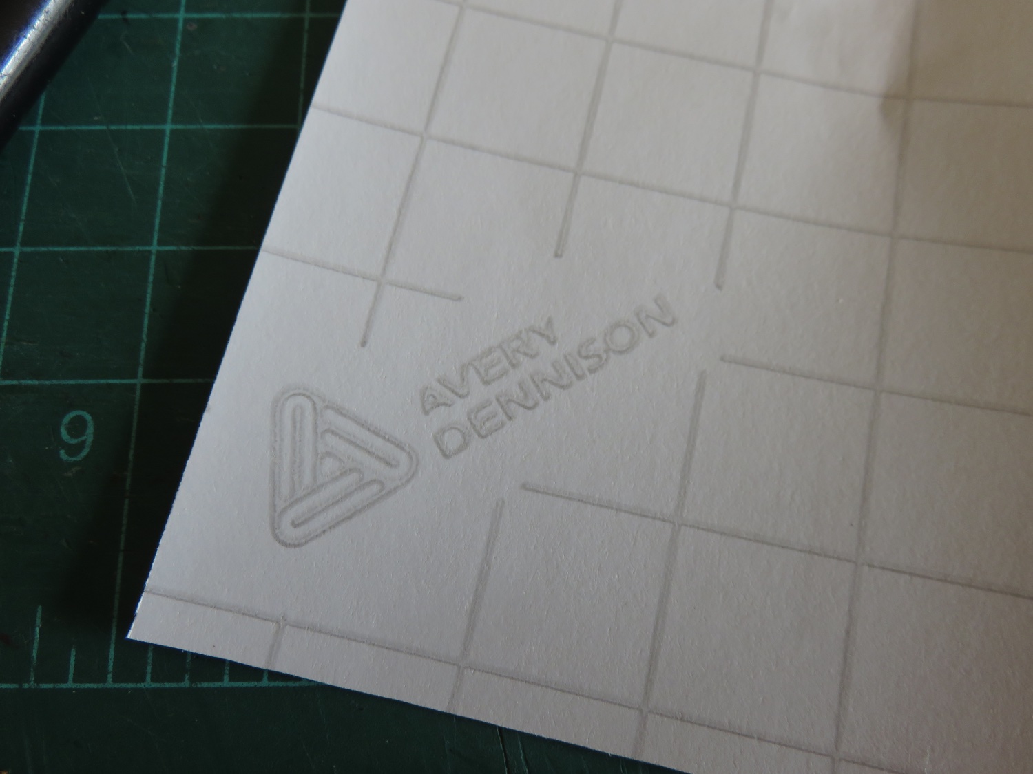
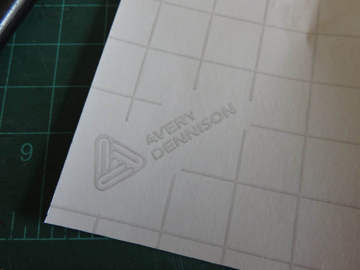
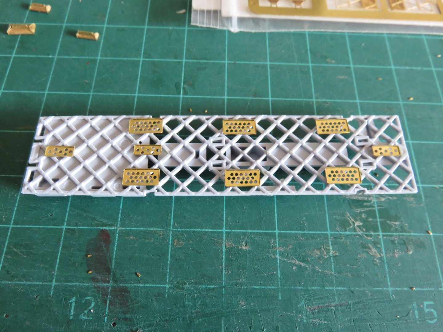
Another day of work on the bomb bay. I think I've got the plates in about as close to the correct position (per the instructions) as I can get. I found that by making up one of the longitudinal bomb beams, and carefully studying the drawings, I could mark the locations for plates and make sure that they are not going to interfere with some of the other details on the bomb beam (there's all kinds of winch brackets and bomb hangers and other sticky-outy pieces yet to come. I could then attach the transverse end pieces of the bomb bay. This is a little out of order from the instructions, which have you assembling some of the cabin bulkheads first, but for ease of painting and detailing, it is necessary to do things in a different order. There was a decent template in the Airfix instructions to ensure the end pieces are glues at the correct angle, and double checking with a fuselage half confirmed everything will fit when the time comes. As you can see above, on the left (aft) end the transverse frame was moulded in clear plastic. This is due to two windows that are located in this piece, and have to be masked off. Strongly recommend putting the masks on before assembly. While small, with careful manipulation using a dental pick, they can be positioned. The bomb bay side weren't too bad, as they're both one piece, but the other side was a challenge....tiny masking pieces. Very glad I didn't have to make those myself. Strongly recommend anyone else contemplating this kit to get the Montex masking set, for no other reason than these windows are included. To give you some idea how tiny these things are! Hopefully they work, I can only say that I tried my utmost, I may first hit it with a shot of Dulcote to try to seal them before painting. I wanted to get a bit further by mounting the bomb beams, but it turns out, I would be unable to remove the mask(s) if they were installed (that would be a bit of an oops!). Looks like they will have to be assembled separately and installed after painting. Hmm.... Avery Labels...... who knew? Andy

- 174 replies
-
- 11
-
-
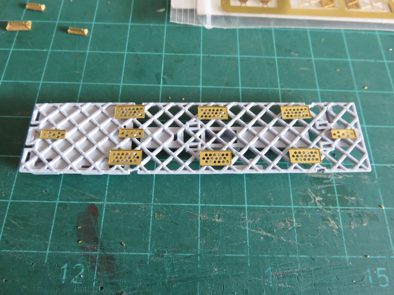
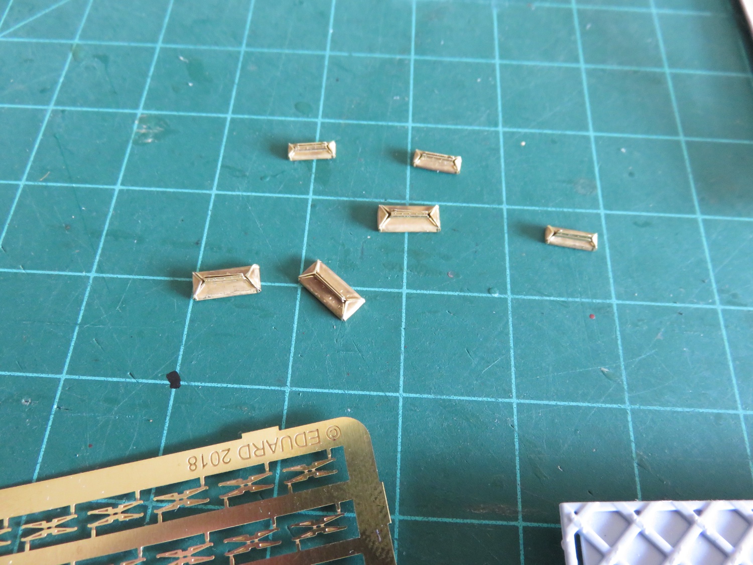
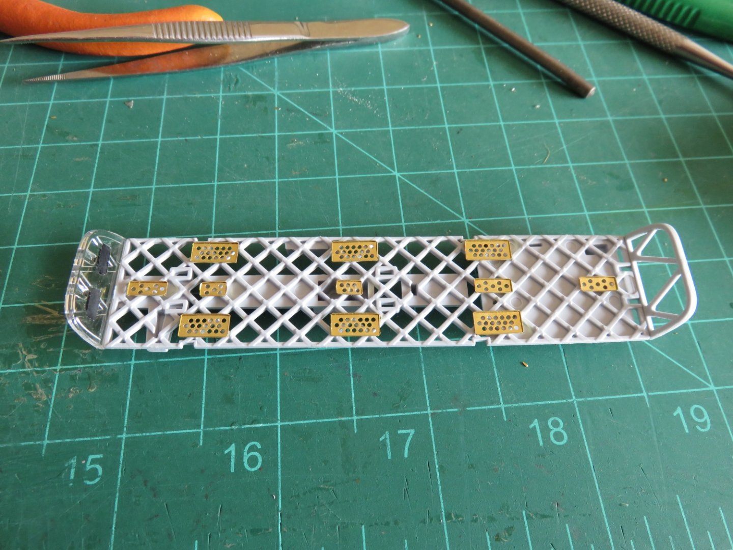
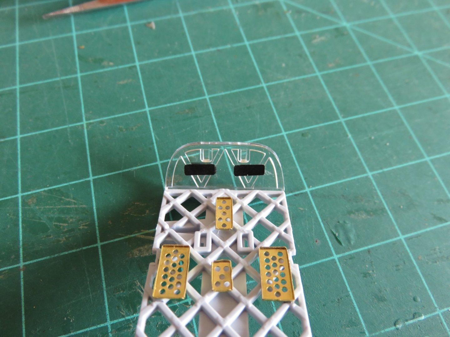
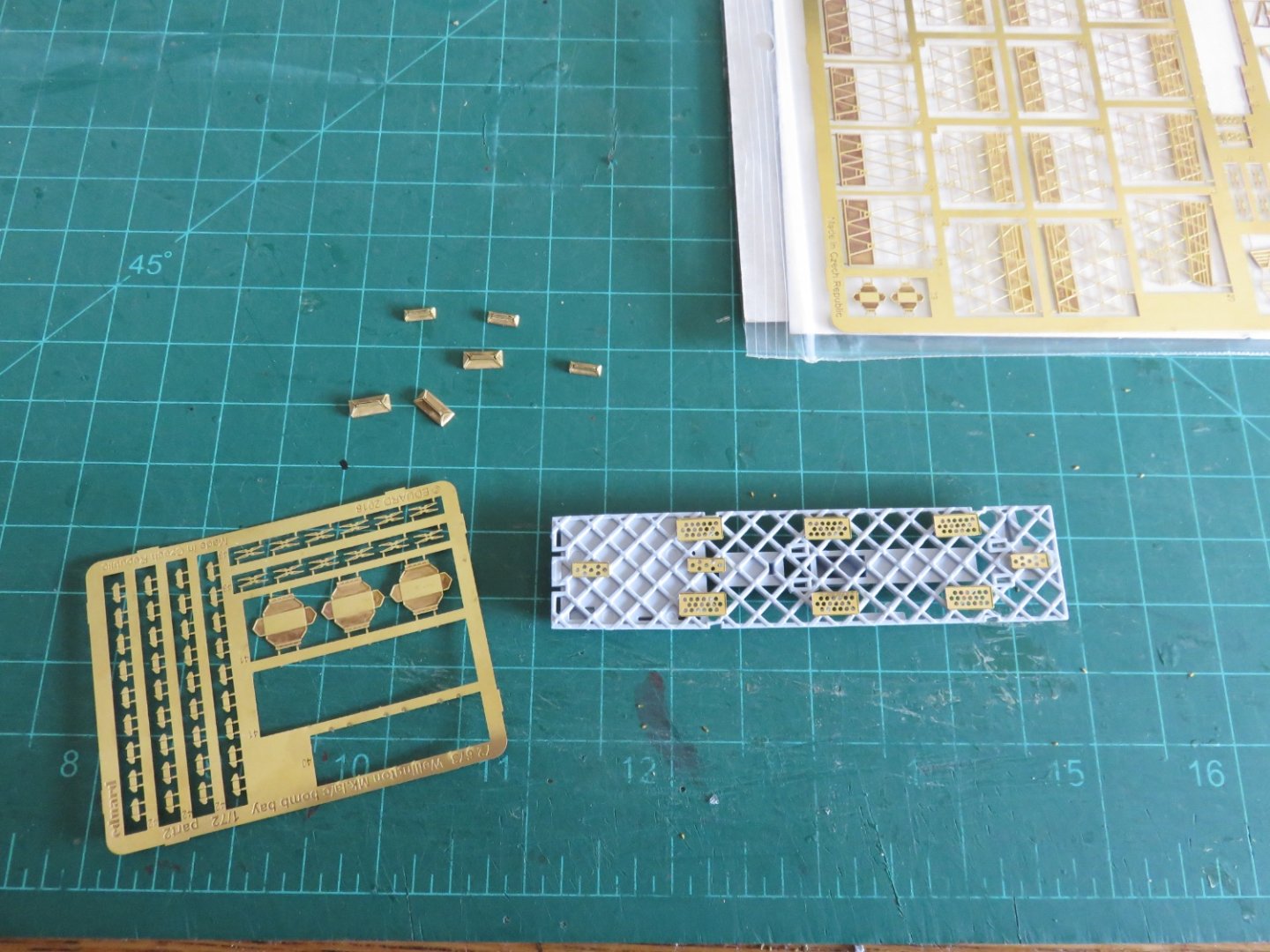
And, we're off! A small marathon of Eduard origami has begun. I figured I could start with some of the bomb bay details, as they will all have to painted the same colour anyway. There are these tiny box structures with perforated plates bases (tops?) that sit below the bomb bay walkway. Not sure of their prototype purpose, but this is step one. A view of the prototype can be seen here. The boxes are missing, but the perforated base plates can bee seen. Here's where things stand so far. There are four different types, although the last two only differ in the pattern of the perforations, the box structures are the same. Haven't quite got to folding them yet. There's a limit to how much tiny PE one can fold in a single setting. A rough idea of the layout under the bomb bay walkway. Everything's just sitting there, dry fit, for the time being. The two remaining perforated base plates are supposed to sit along the centre line between the other larger perforated base plates. A small frustration with Eduard, though, the instructional drawing is isometric, and the depiction of the basket weave framing is only rudimentary, so there's no way to really accurately locate the position of the base plates. I guess close will have to be good enough. While the base plates just require bending a flange around the perimeter, the boxes are a bit more complex. Kind of like a miniature hip-roofed bungalow with a vertical flange along the roof peak. (That's a 1/2" grid on my cutting mat to give some idea of scale). I've gotten away with crunching only one so far, thankfully the brass seems reasonably soft, and the piece has since made a full recovery (currently resting comfortably in a sealed Tupperware container alongside close friends and family). It's nice to be back to building small fiddly things again. Andy

- 174 replies
-
- 11
-
-
Thanks for joining in the fun! The Airfix rendering of the bomb bay is done well enough for plastic, in 1:72, but when I looked at a few different models (like the Avro Lancaster, or the HP Hampton), there was simply no matching the Wellington in terms of complexity, so I absolutely had to go for the upgrade. Andy
- 174 replies
-
- 10
-
-
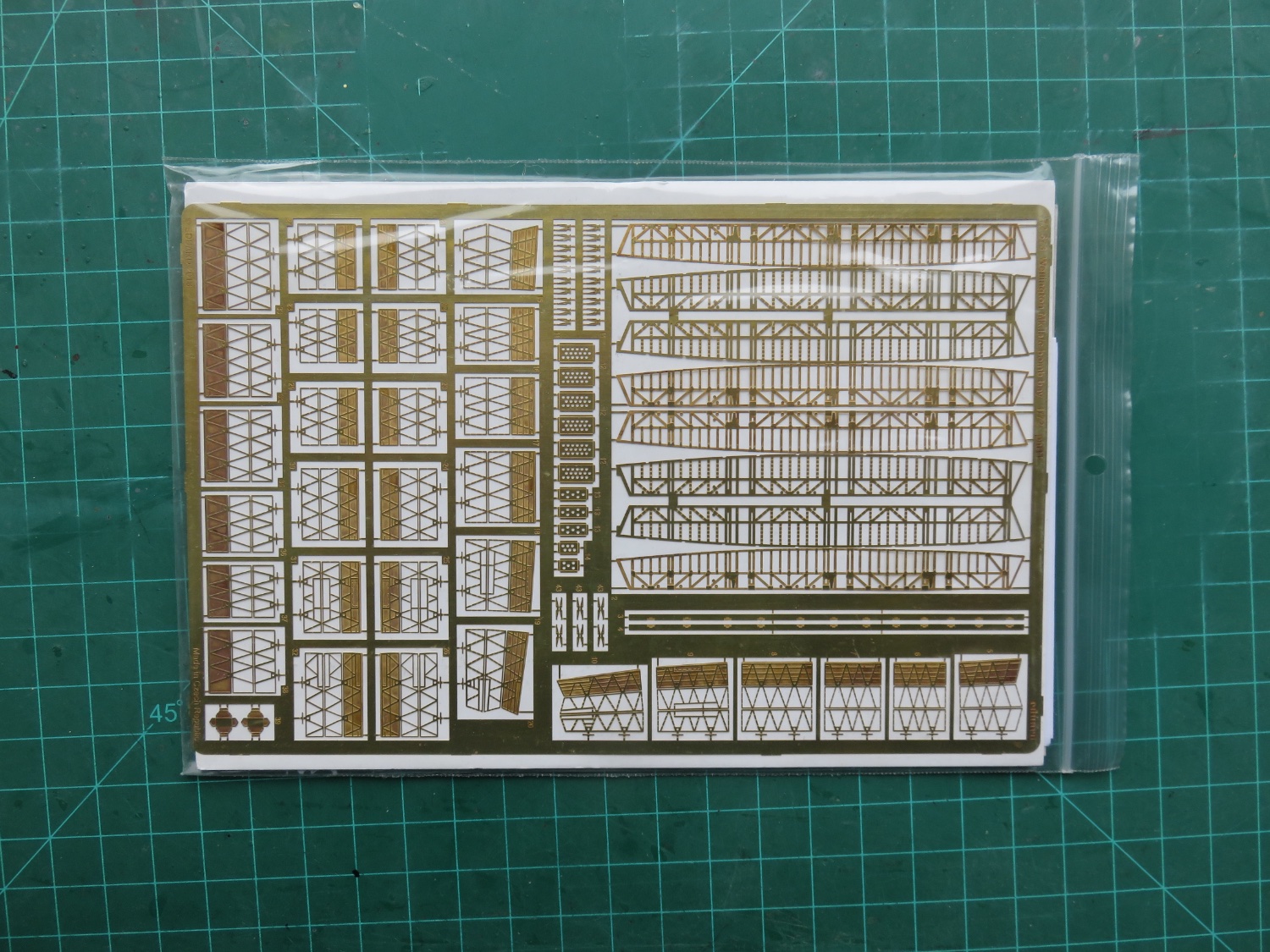
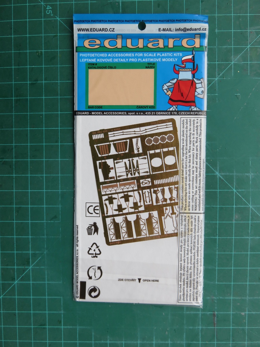
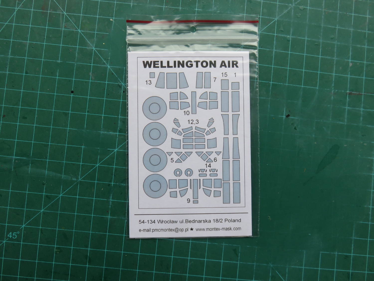
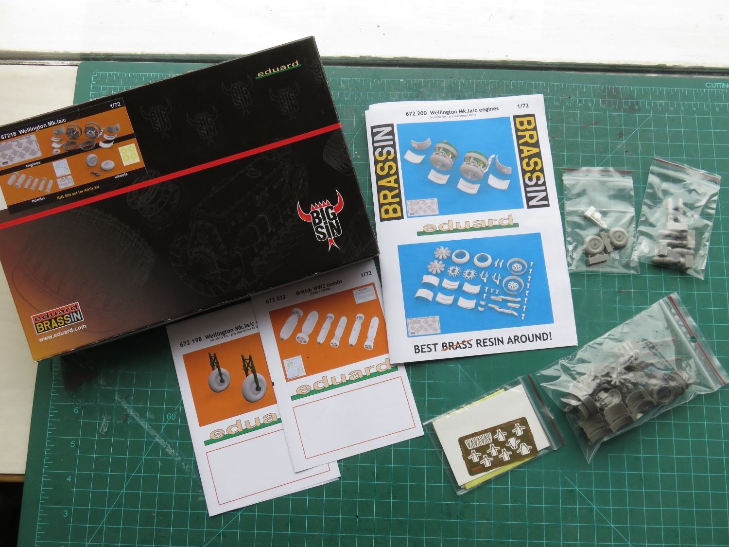
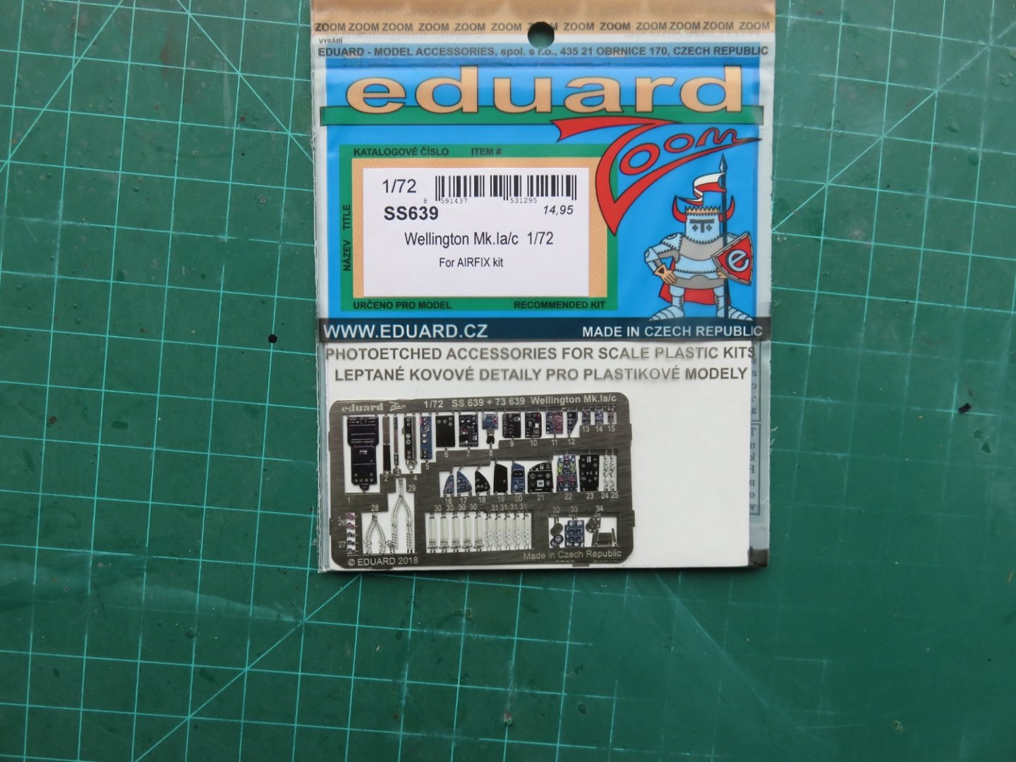
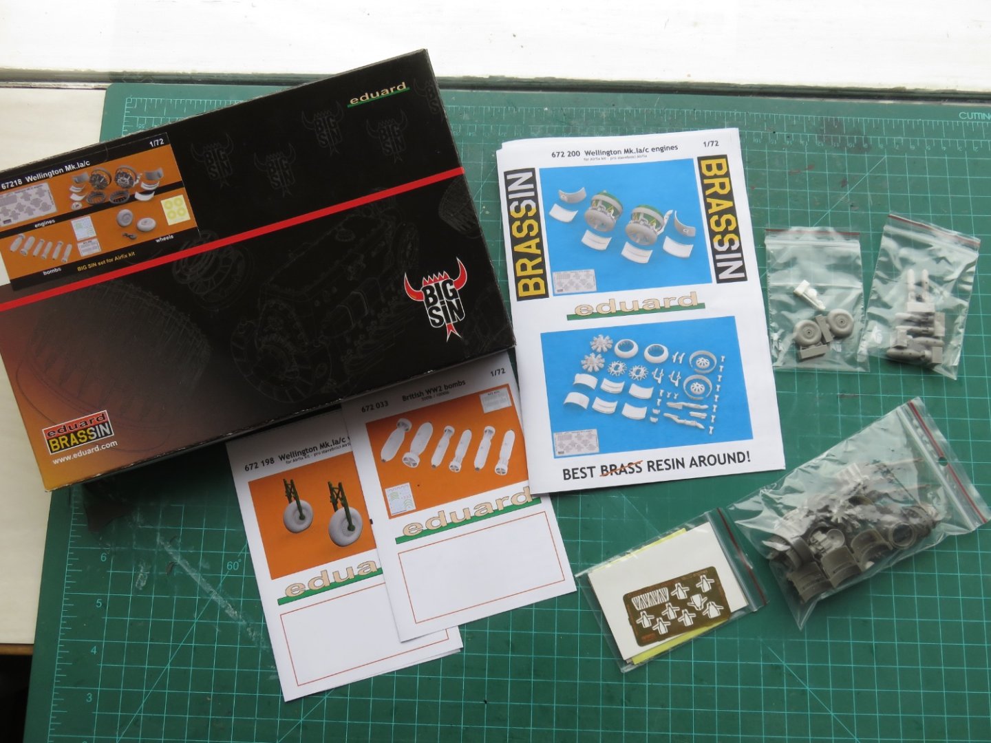
Moving on... It's Here! It's Here!! It's Here!!! (Even better, I didn't get charged any duty! YAY!) So what did the mailman bring? First off, a tip of the hat to BNA Model World, everything arrived well packaged and in great condition, and definitely within the posted timeframe (14 business days, out of the estimated 10 to 20). About the only (very minor) issue was that I didn't get a tracking number until the items landed in my own country, but otherwise service was excellent. Now back to the box! First up, a sizeable selection of PE from Eduard: Starting with the bomb bay and bomb bay doors. Next up, seatbelts and cockpit gauges, as well as radio and other instrument panels. Pre coloured too! (Neato!) Some more internal and external details like landing gear doors, throttle leavers, break lines and the like. This set is actually for the MK II kit, as the Mk Ia/Ic was not available, but aside from a few extra details specific to the Mk II Merlin Engines, the rest is identical to the Mk I. The last bits of details from Eduard, a three piece kit that includes resin wheels (with the "Dunlop" tire branding), some more bombs, and upgraded engines. I am really looking forward to the engines, they're considerably more detailed than the Airfix offerings (and a good reason to leave off a panel or two to show them off, maybe add a maintenance scaffold). Finally, the last item: A masking set from Montex. I veered away from Eduard and other options, as Montex offered masks for the little bomb bay windows, where the others didn't. I should mention, there is one more PE set made by Eduard for this kit, the landing flaps, but I decided not to order this set. I need to order some paint in the coming days, before I can begin building, but luckily I can source that locally (within my own province), so that shouldn't take too long. Let the fun begin! Andy


-
To further my previous point, and provide you with a far more detailed answer: Andy
-
A couple of years ago I’d ordered some items from a seed company in Manitoba (vegetable seeds). The shipment got as far as the local post office and never moved again. After an appropriate amount of time (about two weeks after the “expected delivery date), I contacted the seed company, they were really good about it and I was refunded my purchase. But ever since then I’ve been paranoid about Canada Post…. This is one of the few times I’ve been able to follow a package via a different postal service (I can track on either Australia Post or Canada Post), and I must say that Australia is much more open about the various stages. Lots of details like when the package was booked to fly, what time the plane left, what time it arrived and departed the various depots etc. With Canada Post it’s just “item arrived at facility” “item processed” then four days of nothing followed by “item processed” at a different facility. Big difference. (BTW, I do understand the seven day delay in Melbourne waiting for a flight). Andy


-
Small update: according to Canada Post my package has crossed the country and is now in the same province as me. The alleged expected delivery day is tomorrow. It almost feels like Christmas…… Andy
-
Colour matching is always a hard task. I don’t doubt the accuracy of yours. It’s a source of much continued debate in the model railway community, memories, like colour photos, fade over time. Even after someone manages to find an actual factory paint chip from the period with the actual colour formula written on the back, there’s always some old crank or another who’ll swear up and down it was something else (“just look at this colour photo I took on a bright sunny day seventy years ago”). Can’t wait to see that Lanc! Andy
-
I wonder if that’s also a result of the different camo colours. The green on grey(?) over black looks quite a bit muted compared to the green on brown scheme (to me, at any rate). Andy