realworkingsailor
-
Posts
3,271 -
Joined
-
Last visited
Content Type
Profiles
Forums
Gallery
Events
Everything posted by realworkingsailor
-
 Well, a bit of a surprise this morning. I received an email notification from Australia Post saying my package had landed in Canada, and it looks like it even cleared customs. Hooray… I… uh… oh wait… it’s in Vancouver…. The other side of the country… well…. Hmm…. I am now at the mercy of Canada Post…. 🙄 Andy
 -
Found another interesting film: This is turning out to be a particularly fruitful rabbit hole to dive down, as there seems to be a number of vintage films posted on YouTube featuring Wellington bombers (accompanied by appropriately fraffly accented narrators 😜). Andy
-
A short video showing the Wellington prototype: Still waiting for my order to arrive from parts unknown, until then…. 🤪 Andy
-
I noticed that conversion kit, along with all the other aftermarket products available, listed on Scalemates. For sure that would be an eye catching model! Andy
-
Another one for good measure: A couple of old film reels, one showing some training torpedo operations. The other gives an explanation of the Wellingtons that we’re fitted with the “Directional Wireless Installation” (DWI). A code name for the large electro-magnetic hoop used to detonate magnetic sea mines. Although these specialty variants were never produced in large numbers, it all shows the versatility of this aircraft in a number of different roles. Andy
-
Another interesting propaganda film to help pass the time until my parts arrive from the far side of the world. This one is from 1943: Not quite as cheesy as the last one… Andy
-
That seems to have been a running issue with many bomber designs, bailing out was a bit of an afterthought. If I read correctly, only the Halifax had one halfway decent exit. I’ve seen pictures of the belly turret: https://www.bombercommandmuseumarchives.ca/aircraftphotoessays/aircraft_photoessay_whitley.pdf Scroll through to pg 9. I can’t imagine hanging out in what looks like a trash can, let alone getting shot at trying to shoot back. I think the experiences with the Whitley proved that the design left a lot to be desired, and it was never widely adapted elsewhere. Andy
-
48th Scale imperial rulers. Where?
realworkingsailor replied to John Murray's topic in Modeling tools and Workshop Equipment
Try here for something more closer to your location: https://www.bnamodelworld.com/index.php?route=product/search&search=Scale ruler Andy -
https://uk.airfix.com/products/vickers-wellington-mkii-a08021 Just saying’, is all… Andy
-
Found this restored British propaganda film from 1941: Andy
-
Hi John, I’m glad I’ve caught your interest. After @Old Collingwood’s post above, and now yours, it seems like a good chance there might be more MSW members with a connection to this aircraft. I truly hope my modelling skills can live up to those legacies. Andy
- 174 replies
-
- 10
-

-
Small update. I placed my order for the aftermarket PE and detail sets from BNA Model World. Shipping was not as dire as I had anticipated ($15), estimated travel time of 10 to 20 business days, still not crazy. Nice that all prices where automatically converted for me to Canadian dollars. Took a lot of guess work out of the equation, although the Loonie usually favours the Aussie dollar by about 10%. I fully expected a slow process to accumulate the required ancillaries. Next up is getting the remaining paints that I will need. Some colours I've managed to substitute from stock I have on hand (from colours that match very closely to the Humbrol colours specified by Airfix), so it's really only a couple of specific colours that I will need. In the interim, some vintage footage (no sound): (Also happens to be #75 (NZ) Squadron) Andy
-
Great picture! That’s a Mk II (you can tell by the Merlin engines). If I’m not mistaken, they were built concurrently with the Mk Ia/c variants, so they share many of the same fuselage features (windows, turrets, etc). Have you had a chance to go through that photo essay I posted earlier? I could easily spend hours going through it with a magnifying glass hunting for details! Andy
-
So other than travel time, nothing to really worry about. Thanks EG! Between here and some cursory searching online, there’s almost nothing but positive reviews of BNA, I feel a lot more confident, and I’ll be ordering from them shortly. Andy
-
That’s awesome! Amazing how much apparent damage that airplane sustained, but thankfully the structural damage was really minimal, and, through heroic efforts, was capable of continued flight. I have a feeling that a Wellington could fly as long as the wings and flight surfaces had enough cavas to function, the rest of the plane could have been nothing but bare frame! I am thinking of modelling my version in a more “as delivered” set up, with the windows still clear. Long term I may make it into a bit of a diorama, and I’ll place some black panels on the ground waiting to be fitted! Andy
-
That looks really nice! I’m planning on going semi-mad-daft with respect to the details, regardless whether or not they will be visible. 😁 I’m also thinking of bending the rules slightly. I had heard of story of Sgt. Ward a long time ago, and knowing there was a Canadian connection kinda sealed the deal, so I’ll be doing the 1c version. Although, it’s the version with the blanked out windows, I may leave them clear nonetheless. In the Wikipedia article on Ward, there’s a photo of his plane (you can see where he punched through the skin): But also, it looks as if the windows were simply painted or otherwise blanked over sometime after the aircraft entered service. To my mind, it is possible that the plane left the factory with the windows clear. I’ve also located a great photo essay from the bomber command museum in Canada: https://www.bombercommandmuseumarchives.ca/aircraftphotoessays/aircraft_photoessay_wellington.pdf There are precious few captions, but it shows that even among identifiable variants, there was a variety of different arrangements. For example if you go through and look for the Mk II variant (easy to tell because it’s the only version with Merlin inline engines), there are some aircraft with no side windows, others with only the long over wing windows, some have only the triangular waist window, and yet others have both. I think that, unless you’re planning to model a specific aircraft, on a specific date, at a specific time, at an exact location, there’s enough historical leeway (as far as Wellingtons go), that some liberties can be taken without running the risk of thumbing your nose at history. Besides, I didn’t really fancy the idea of punching little holes all over my model anyway 😁. Andy
-
Thanks guys, any issues to be aware of when ordering from overseas? (Other than the usual customs “surprises” from my own country). Andy
-
There’s another technique some model railroaders use you can try to replicate pealing paint. After applying your base staining, brush on some rubber cement to selected areas. After the cement has set, apply your top colour, and when that dries, simply rub off the rubber cement. Andy
-
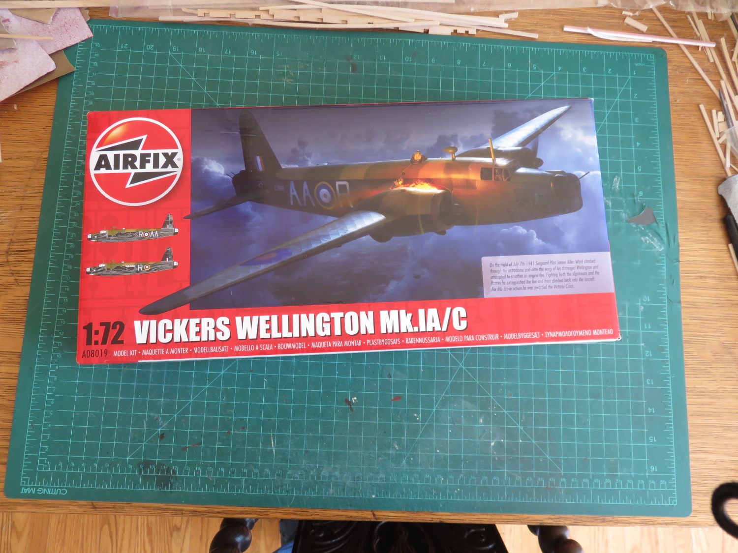
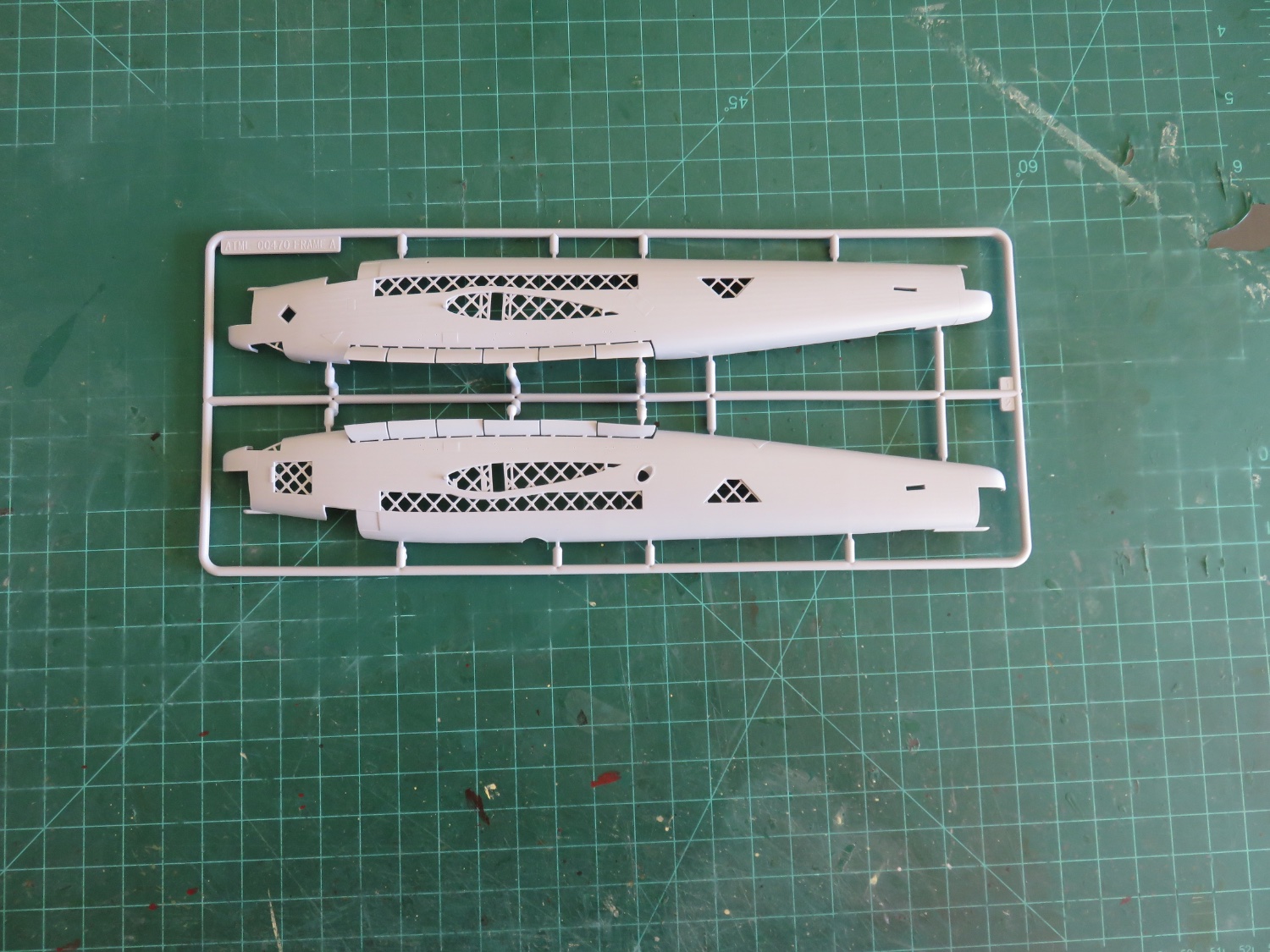
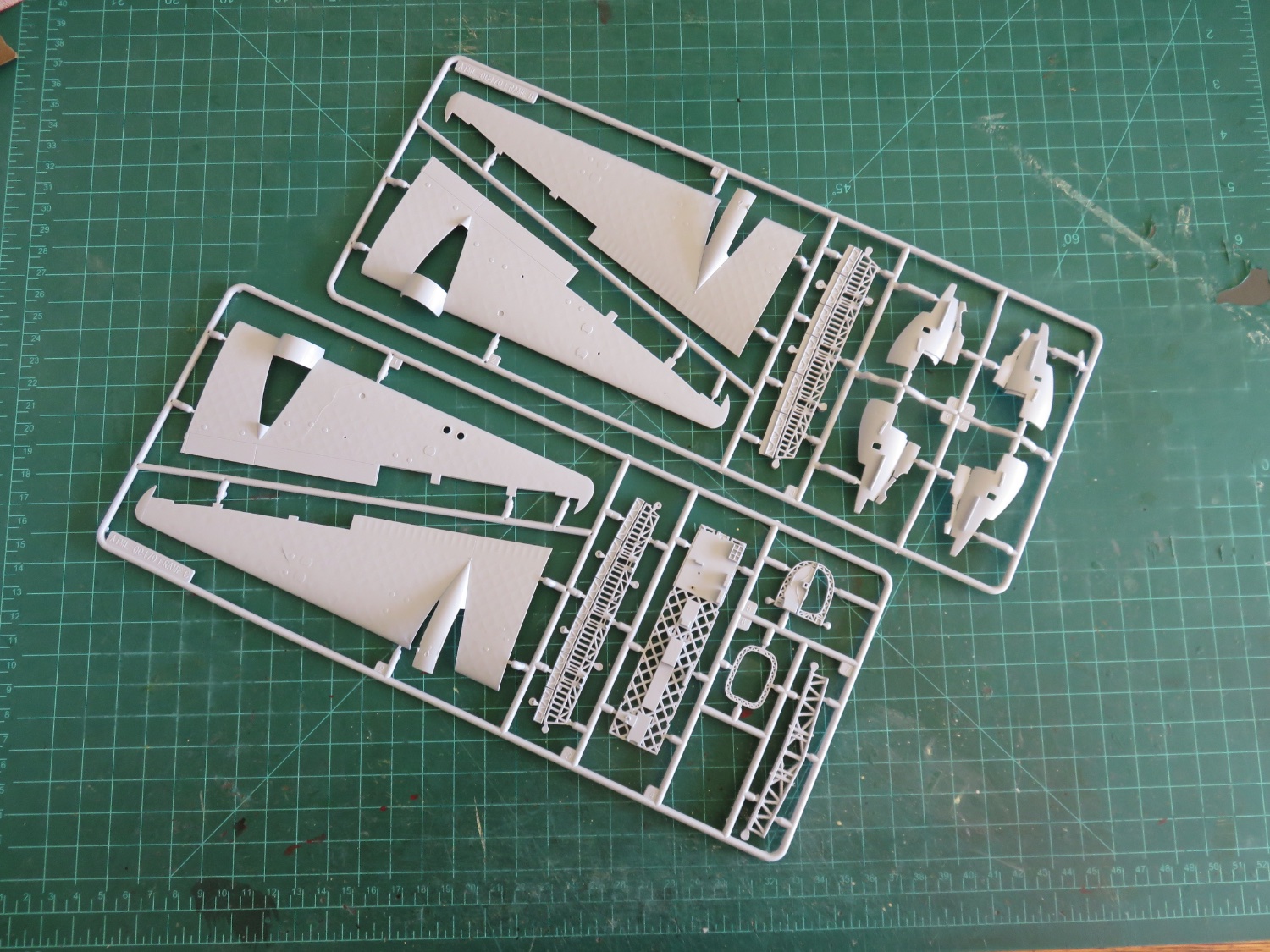
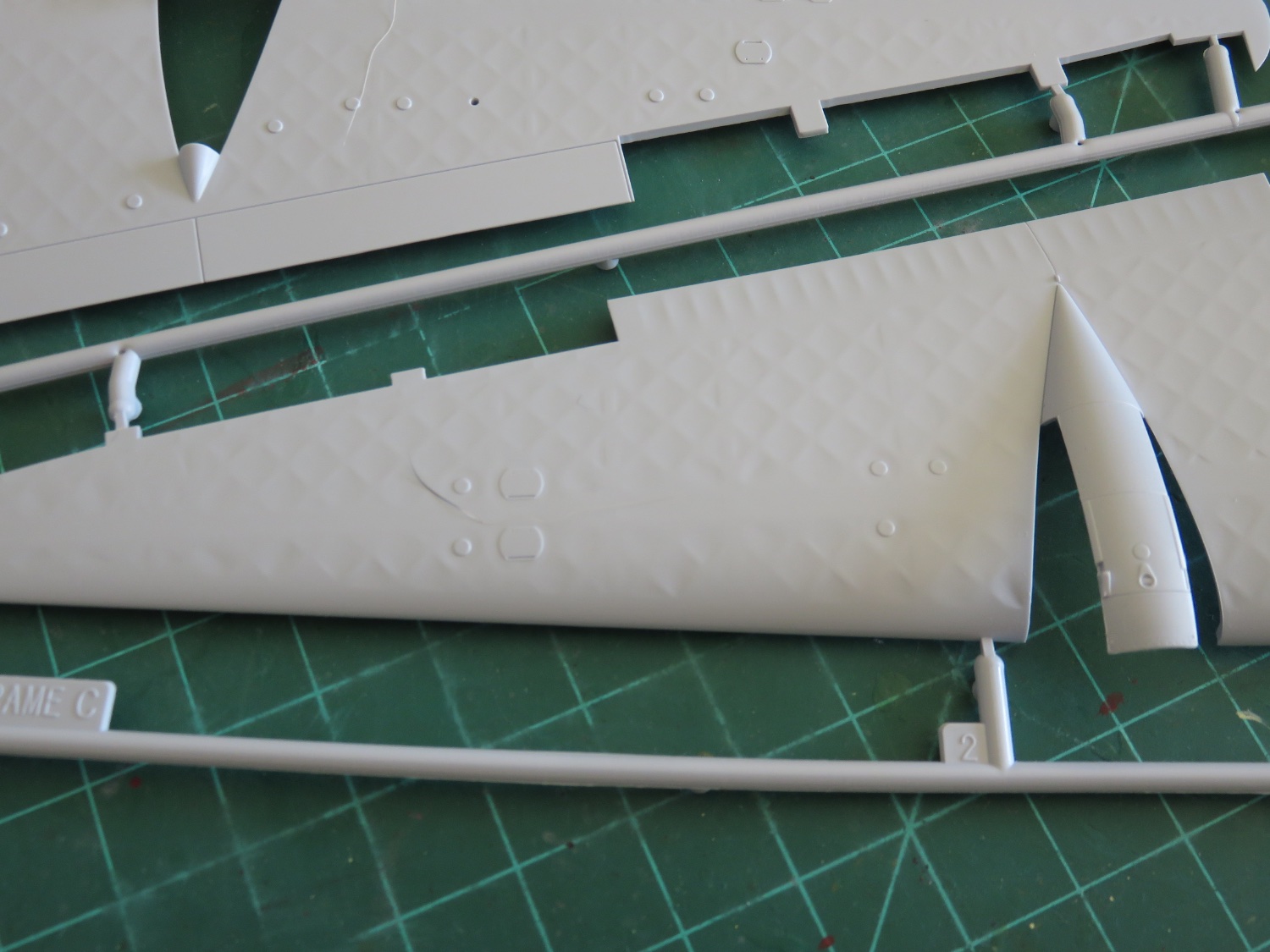
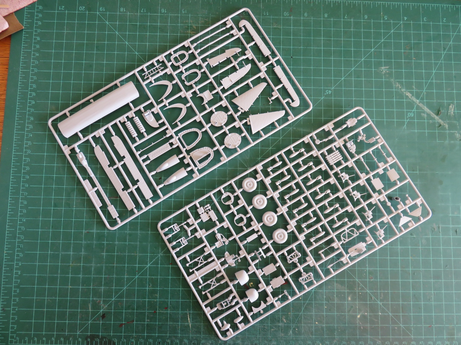
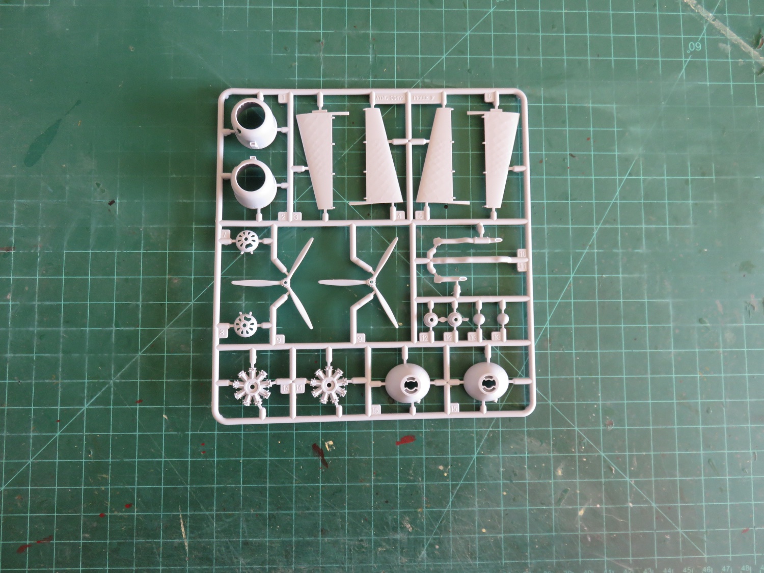
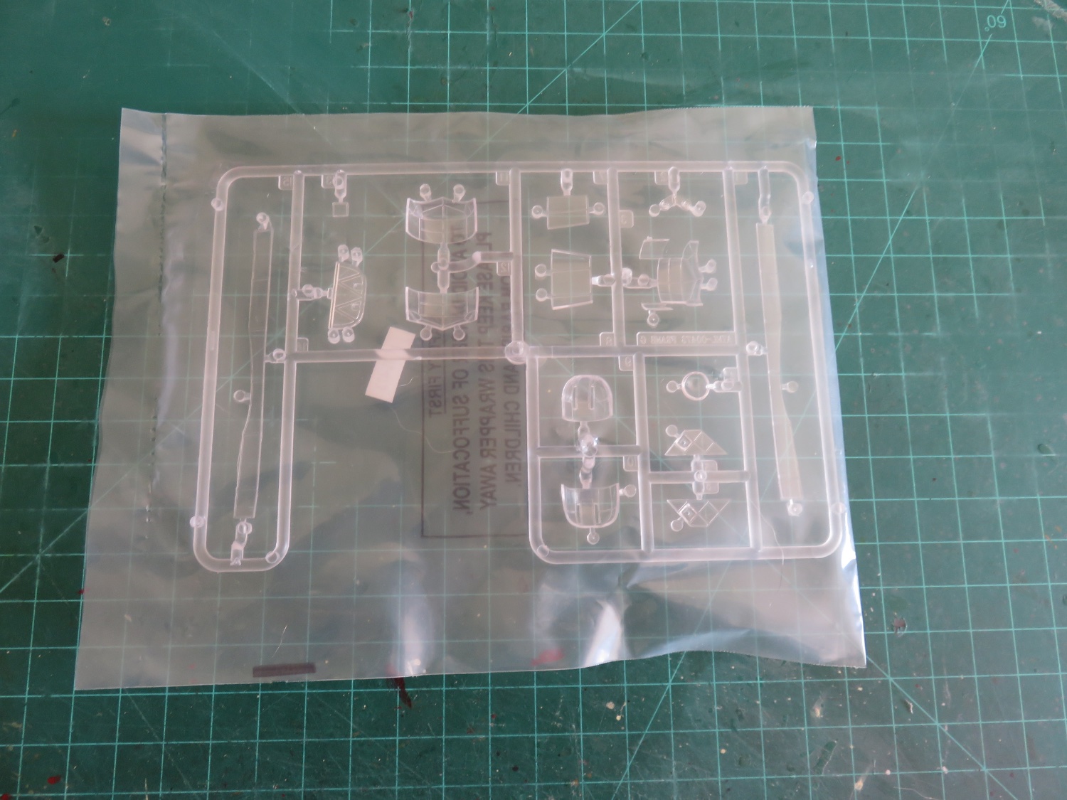
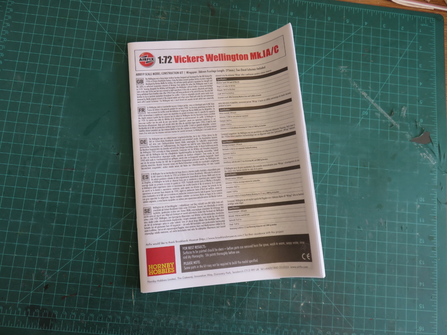
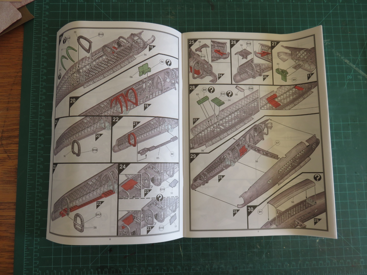
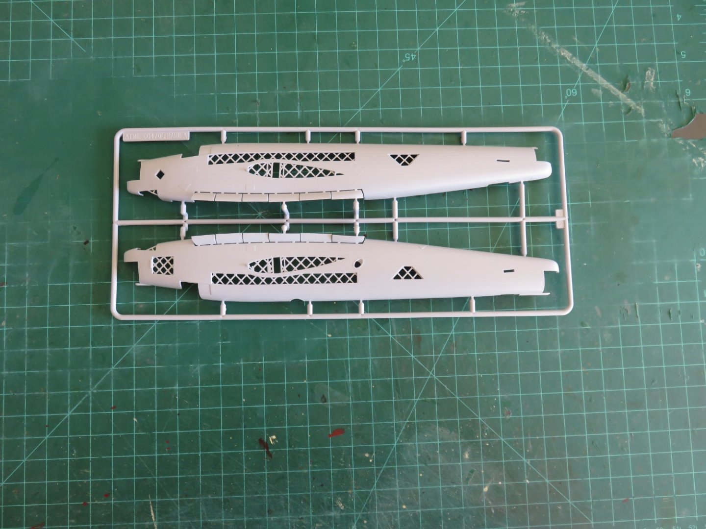
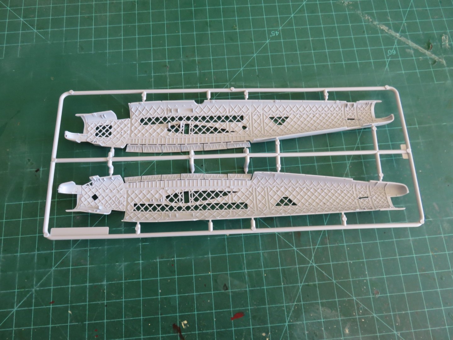
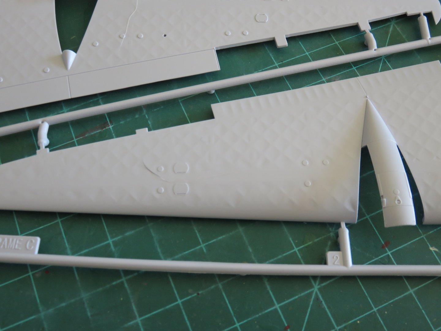
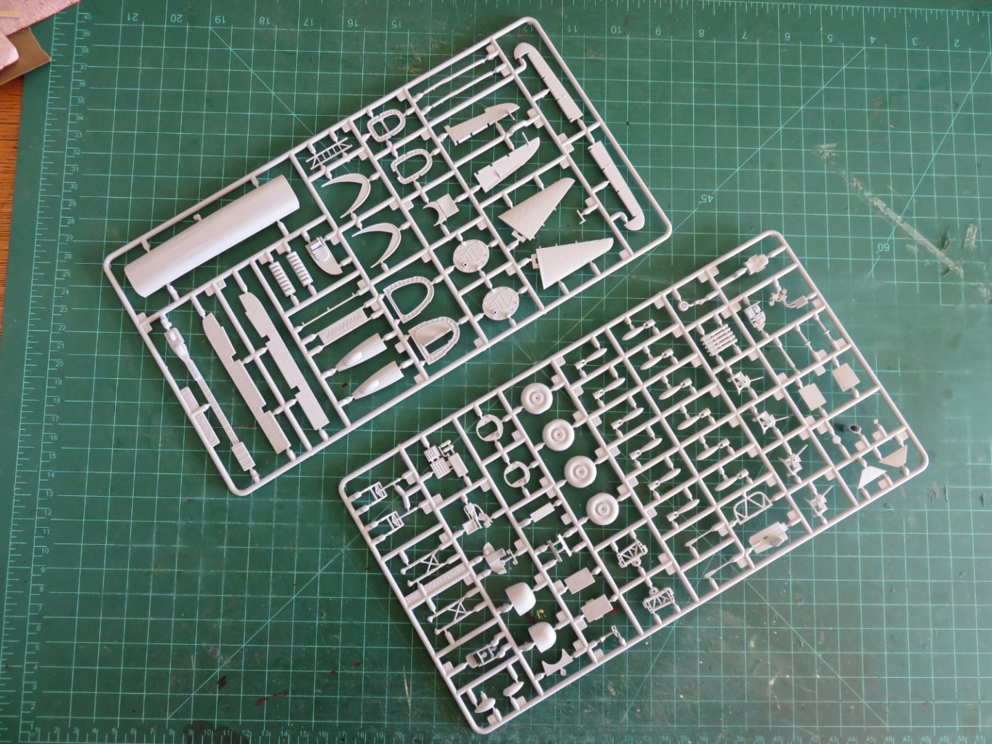
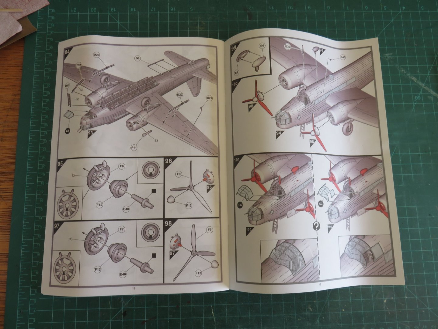
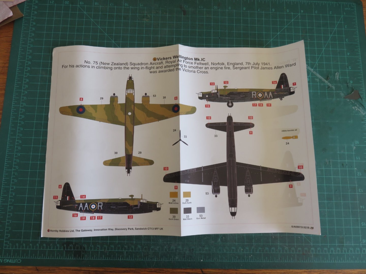
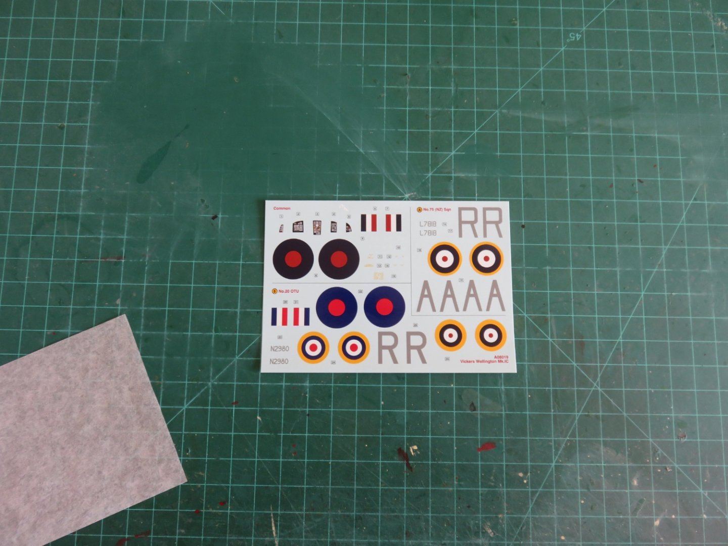
For my fall hobby project, I’ve decided to go in a completely different direction. I’ve been silently (and in some cases less so) flooding in on many of the amazing model airplane builds around here. Quite frankly, a “little bit” of “fear of missing out” has crept in, so I felt I had to join in. Aircraft are not a usual subject for me, but I have built them in the (now distant) past. I also decided that I would attempt to go beyond just making the model strait out of the box, so I’m looking at purchasing a few aftermarket PE sets (more on that later). Over the summer I read “The Bombers and The Bombed” by Richard Overy, not an easy read, (a more accurate title might have been “Statistical Analysis of the Bombing Campaign Over Europe 1939-1945”, but I doubt that would have interested anyone beyond university history majors). Suffice it to say, as far as subject matters go, it helped to nudge me in the direction which you will see here below and following. After looking at the multitude of options for model aircraft available online, I opted for the Vickers Wellington. Partially because I had made a model of one over 20 years ago, and partially for the same reasons that drew me in back then, it’s a pretty interesting airplane. For a more complete rundown. check here. A remarkable aircraft, it was building using a geodetic frame that gave it incredible strength, at a great savings of weight relative to conventional construction at the time. Production began in 1937 and continued right through the war, with the last Wellington rolling out in October 1945. A whopping 11,461 were built, despite the complexities of the geodetic construction. It was the most numerous British bomber, and the only British bomber to see production through the entirety of the war. Sadly only two complete aircraft have been preserved, neither in flying condition. Kit overview As I mentioned before, I had built a model Wellington many years ago (which has subsequently been lost). It was an Airfix kit of a B Mk III, if I remember correctly. This time around I am again going with and Airfix kit, but it is a far cry from the one I remember. The kit completely retooled in 2018 offering the builder a choice of either a B Mk Ia or B Mk Ic. Airfix has also released a B Mk II (with Rolls Royce Merlin engines), as well as the coastal command variant GR Mk VII. The Airfix Box Art The kit includes six sprues molded in grey plastic, as well as one in clear plastic which contains the windows and other “glass” components: The fuselage halves The inside The kit includes an almost completely detailed interior. You can see in the above photo, the interior shows the geodetic framework. That's going to be fun to paint! Two sprues hold the wing components as well as the engine fairings and parts of the bomb bay. Up close, the geodetic structure is visibly molded into the wing surfaces, as well as a multitude of other small details (The dog hair is a free aftermarket addition). There are a lots of parts that make up the interior detail, there's a full section for the radio operator and navigator, the flare chute as well as what I think is the toilet. There many options for the modeller to choose from. Some choices are specific to which variant is being built (1a or 1c), others more general (open or closed bomb bay, landing gear down or up). Engines, propellors and other various parts There is virtually no flash, and the parts are all very cleanly molded (no apparent divots or other molding errors as far as I can tell), I expect a minimal of clean up, only the molding gates. Clear parts The kit includes three options for the canopy. One version has the side windows open, the other two are very similar, except for a tiny difference the the forward corner lower window, I suspect that one version is for a different model, as there are other extra parts as well as other indications that these molds will be used for other the versions (Mk II and GR VII). A nice partial colour instruction book. The instructions do show which parts are likely not to be visible after construction, and marks them in green, leaving it up to the modeller to include them or not. There is also a full colour painting guide for the exterior of the aircraft. Both versions are shown (the second version is on the opposite side). The decal sheet, with markings for both Mk 1a and 1c versions, as well as the restored Mk 1a R “Robert” at the Brooklands museum. Apparently, the colours are a bit more vibrant than the WWII version, and the roundels are slightly different. The Mk 1c version (AA R) was flown by no. 75 Squadron (New Zealand). In July 1941, returning from a raid, the aircraft was attacked by a BF110 night fighter. The attacker was shot down by the tail gunner, but not before managing to start a fire in the starboard wing, near the engine. The pilot (Squadron Leader Reuben Widdowson, a Canadian) ordered the crew to bail out (a wise move, as a fabric covered aircraft won't fly very long with a burning wing). The second pilot, Sgt James Allen Ward had a different idea. He climbed out of the astrodome and by kicking and punching hand and foot holds in the wing and fuselage, managed to make his way out to the fire. By using an engine cover, he successfully extinguished the fire. The aircraft was able to safely return to England (although it crashed into a hedge on landing and had to be written off). For his actions Sgt. Ward was awarded the Victoria Cross. As I mentioned earlier, I am planning on investing in some aftermarket parts. I’ve been looking at the offerings from Eduard/Brassin. So far the best price (and availability) online I’ve found is from BNA Model World in Australia. If anyone anywhere has experience ordering from them, please let me know. I noticed an old topic on MSW started by Danny Vadas, that had nothing but good tings to say, but that was 5 years ago, Just curious if anything has changed since then. I won’t be starting building for some time yet, it’s going to take me some time to acquire the various after market components as well as whatever paints and other materials I will need. I need to do further research, while the instructions are decent, they don’t make any distinctions as to which parts/modifications are needed for which version (other than which fuselage windows need to be blanked out). Andy


- 174 replies
-
- 14
-
-
Canadian Pacific experimented with bay window vans in the late 19th century. They didn’t work so well in the winter, as the snow would accumulate and block the windows. I found a couple of photos here (3rd and 4th from the top): http://www.trainweb.org/oldtimetrains/photos/cpr_rolling/five.htm You can see the construction is almost identical. Andy
-
Looks fantastic! Great to see you back at the bench. I wonder if this tool might help make things easier on your wrists: https://www.micromark.com/Nibbling-Cutter A model railway friend of mine (who was amazing at building styrene structures from scratch) has a set, and they sure speed up the process. Andy
-
Sorry, I don’t have Facebook. Looking at photos available online, there are four cargo cranes surrounding the decked over well deck, so the hatches must still be there: Andy
-
Seems as likely as not, they would have simply extended the hatch coamings up through, unless they had no intention of using the after hold (which seems weird to me). Andy
-
If you don’t mind my interjecting, it looks like in the diagram EG posted, pieces 54 a and b have switched labels with 54 c and d (as shown in Chris’ photo). 54c and d sit inside the wing cutout and a and b glued to the outside to provide support for the protruding part of the cowling. I suspect the printed side of 54c and d faces the inside of the radiator cowling. If that makes any sense. Andy
-
Sanding can’t hurt. If you have a bit of scrap material, apply a coat or two of gloss and see what the results are (with and without sanding). Even better, if you have any leftover decals from another project, you can see how they’ll work (and get familiar with the micro sol/set). I find it’s always better to try a new technique with scraps and leftovers, rather than risking everything on a prized project. Andy