realworkingsailor
-
Posts
3,271 -
Joined
-
Last visited
Content Type
Profiles
Forums
Gallery
Events
Everything posted by realworkingsailor
-
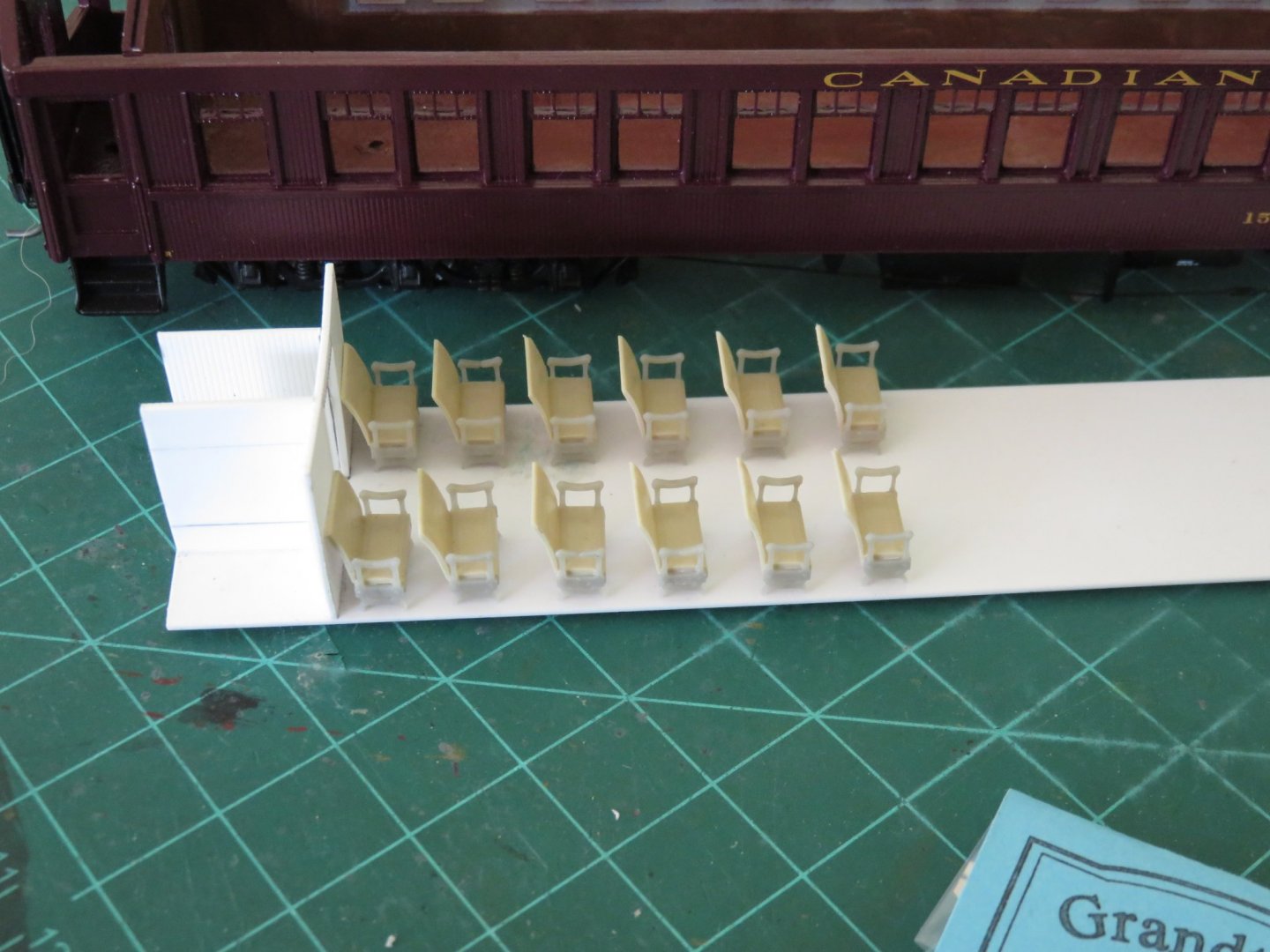
 The last couple of days have seen some slightly cooler (albeit no less sunny) weather. I've begun work on the seating... although... some assembly required. The Grandt Line seats are great, and although they are a D&RGW prototype (that's Denver and Rio Grande Western Railway for the non-railway types), they are about the only proper walk-over type seats out there. Most of the other available seats are the "sleepy hollow" streamliner seats of a much later era. For those unfamiliar, walkover seats could be set up to face forwards or backwards by moving (walking over) the seat back. The seats consist of a beige moulded seat and back, and grey moulded armrests and legs. And as you can see by the 1cm grid on the cutting mat, they are not particularly large. There is a limit to how many I can make in one sitting without going crosseyed! The first few finished examples. These are just dry-fit on the car floor for now. The actual spacing with have to be carefully marked out in conjunction with the windows, and the centre aisle. Hmm... I think that bulkhead needs some attending to as well... it's awfully curvy.... Andy
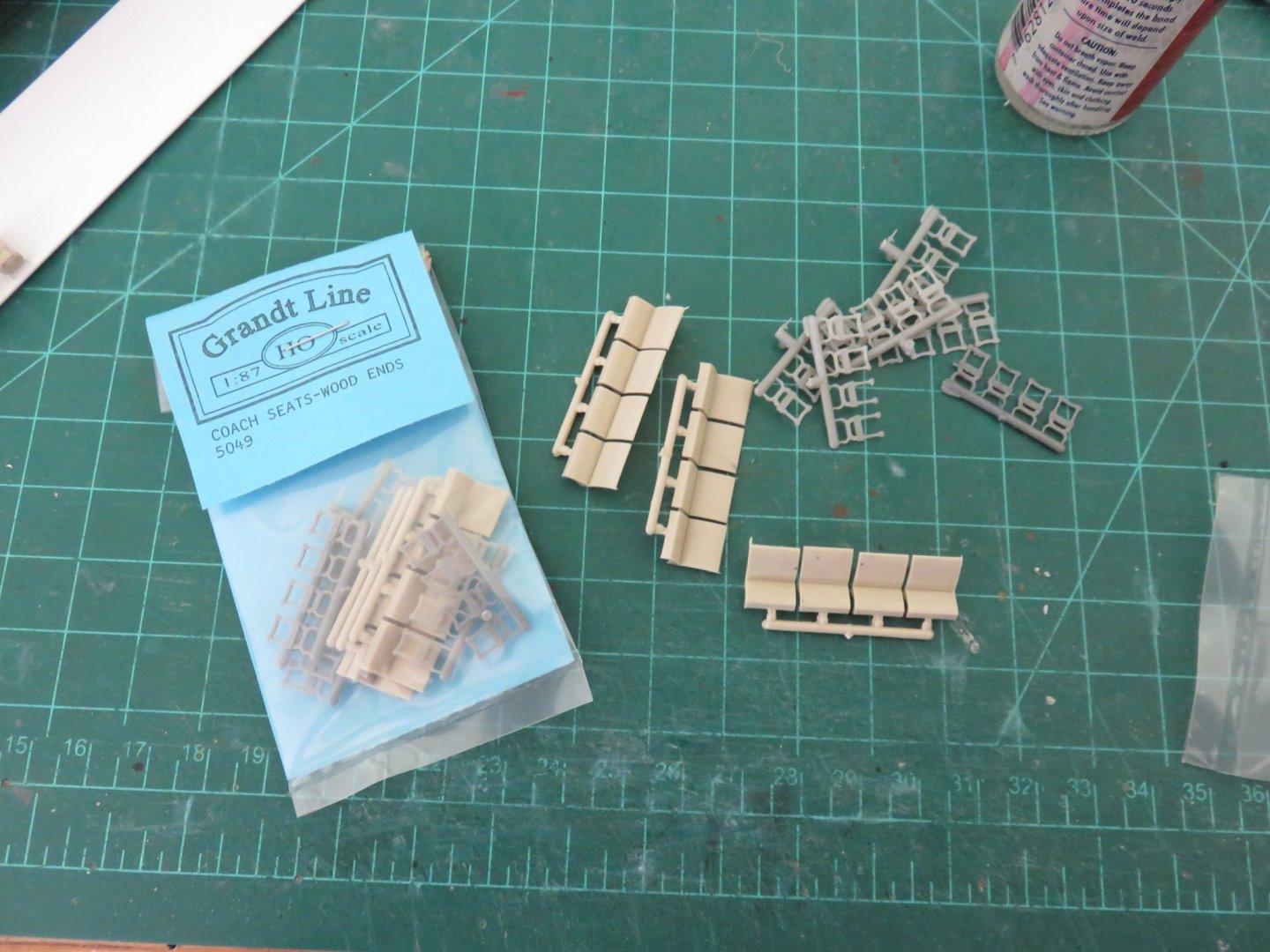
- 154 replies
-
- 14
-

-
So... the strangest thing happened today.... my seats have arrived at last! I was beginning to lose hope, but by some miracle they found their way to my mailbox. I wish they could tell me about all the (mis)adventures they had on their long (and possibly far roundabout) journey, but I will just have to satisfy myself that they are here, now, and that’s all that matters. Order placed April 28th, shipped May 1st... arrived June 9th.... From Milwaukee to Mansfield (Ontario!) in six weeks.... I think one could get there faster by walking! What a truly bizarre world we find ourselves in! For comparison, I ordered some sweet corn seeds (for a summer project 😁) from a company in Brandon, Manitoba, on May 25th. International borders not withstanding, as the crow flies it is, suffice it to say, a tad further away than Milwaukee. My seeds made it here on June 1st... um... hmmm... Anyway, it’s not really good modelling weather at the moment (hot and sunny out😎), so the delay in building will continue. But in the off chance there’s a day when the weather proves more favourable for indoor projects, work will resume. Stay tuned! Andy
-
Thanks everyone for the kind comments and likes. I wish I had an update, but things are on a bit of a pause while waiting for parts (and the recent spell of unseasonably hot weather!). About the only thing I’ve received from Walthers was a customer satisfaction survey in my e-mail. For giggles I decided to go through it. The first question: “Have you received your order? Y/N“ Of course I clicked “No” ”Thank you for your feedback, we’ll contact you again in a few weeks” *blink* *blink* Bwahahaha 😝 I think I’ve been stuck at home too long! 🤪 Andy
- 154 replies
-
- 11
-
-
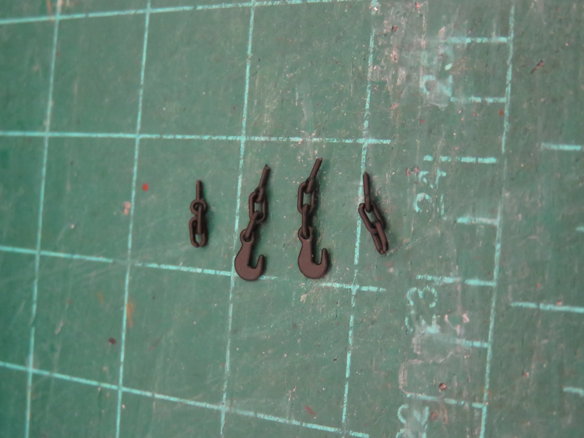
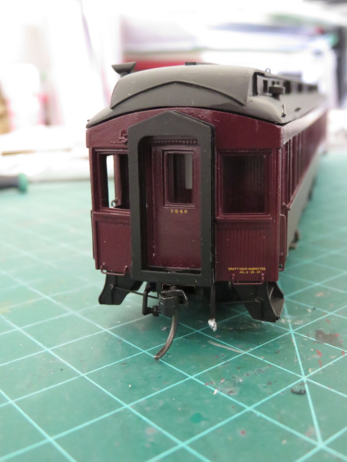
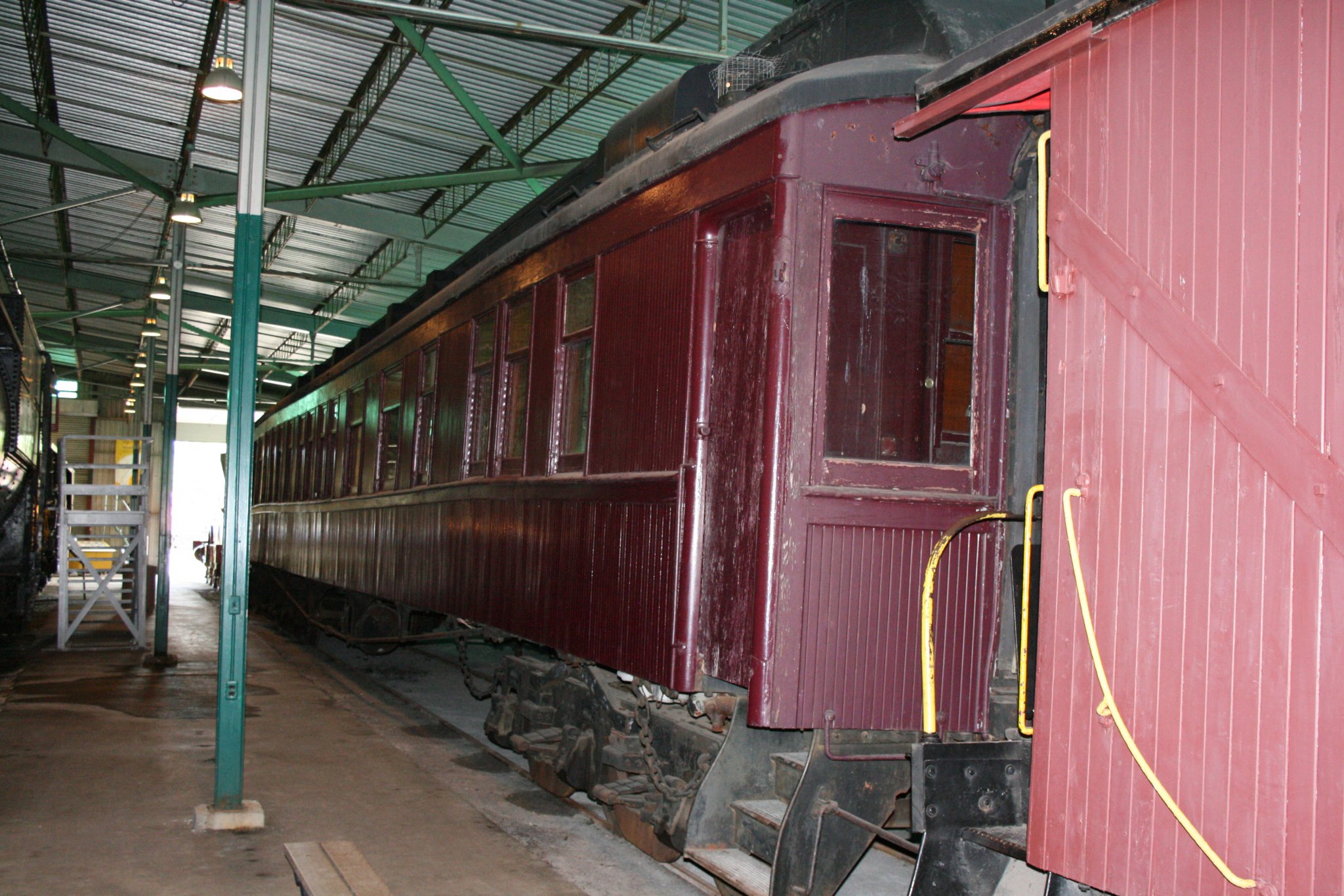
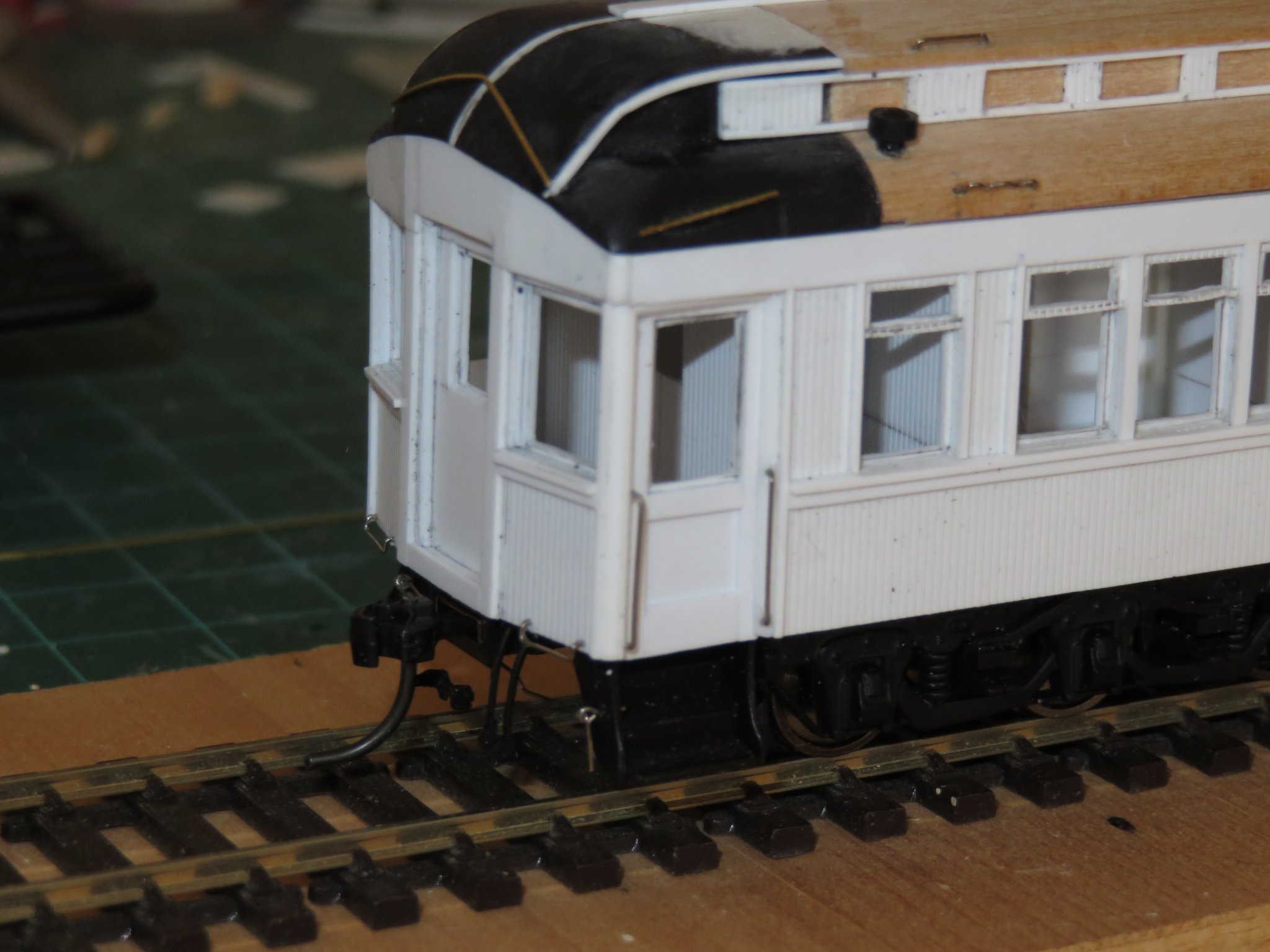
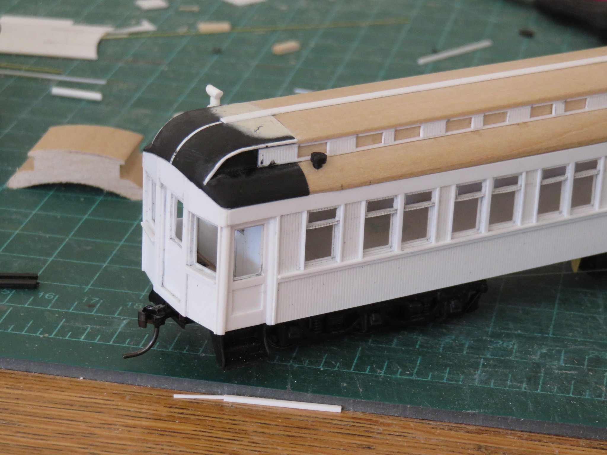
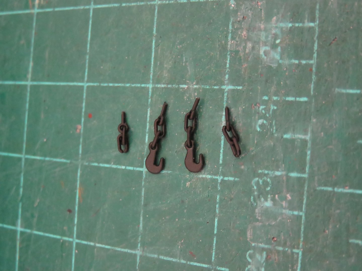
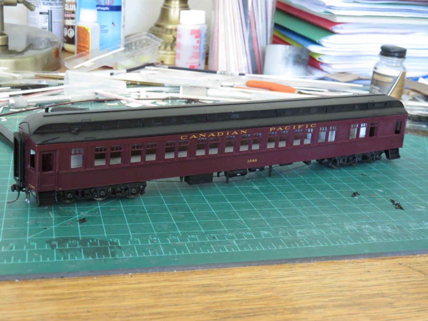
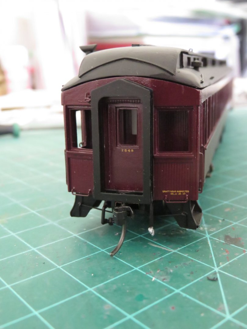
Time for a small progress update. The underside has been painted black and lettering has been largely finished, both sides. The decals came from Black Cat Publishing. Up until the 1930s or so, CPR used gold leaf (actual gold leaf!) lettering on their passenger equipment, and even on their dedicated passenger locomotives too. As a cost saving measure the lettering was switched to what is known as Dulux Gold, a more yellow-ochre colour. Personally, I prefer the Dulux colour better as it adds a nice contrast to the dark tuscan red (it stands out a bit more, the gold leaf gets a little lost at any kind of distant viewing). I have numbered the car #1548. One of three 15XX series cars assigned to the Dominion Atlantic, the others were 1544 and 1551. The decal set even includes service, inspection and test data stencils for the underbody appliances and tanks (you can just make them out on the two air tanks at the centre of the car). A few more end details; the diaphragms have been added (also leftovers from those infallible Branchline kits). The small car number on the door was a lot of "fun" to apply as all the numbers had to be put on individually (they're about 1mm in height). All that remains to be added to the car exterior are the safety chains and hooks. These will be mounted on either side of the coupler. After the chains are on, the car will needs a little touch up (there are a couple of tiny nicks in the paint) as well as a little dusting/cleaning before a coat of Dulcoat is added to seal everything nicely. Then it's on to the windows! Still no sign of my seats yet.... I expect it will be a couple more weeks... maybe...? Andy
- 154 replies
-
- 18
-
-
Thanks! Although I don’t have a home layout at the moment (still in the planning stages), I do have access to a club layout. So when this covid stuff has calmed down, I will definitely get some photos and video of the car in operation. Andy
-
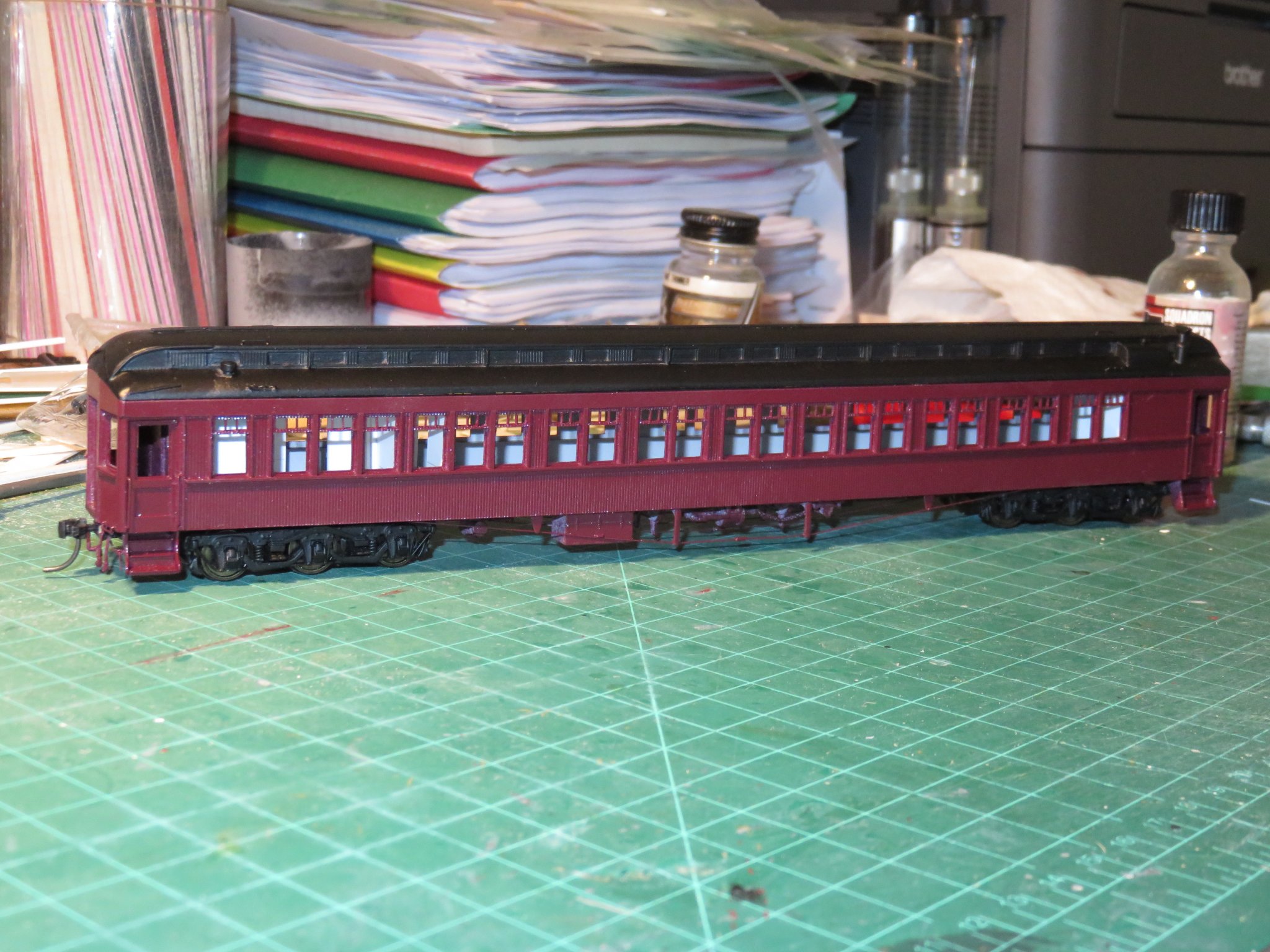
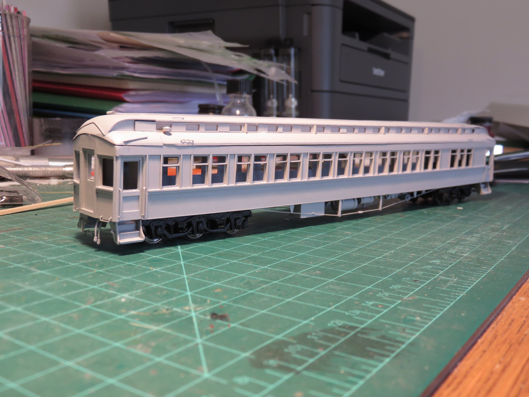
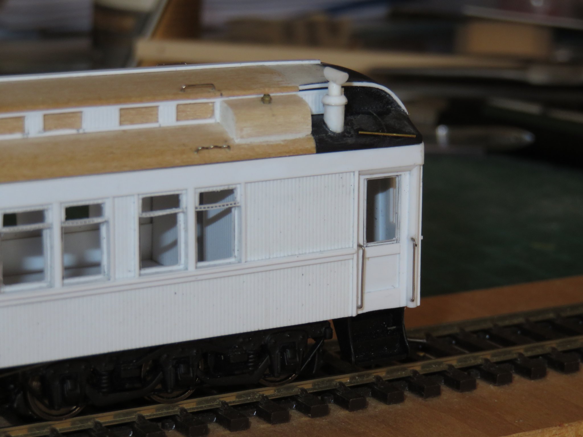
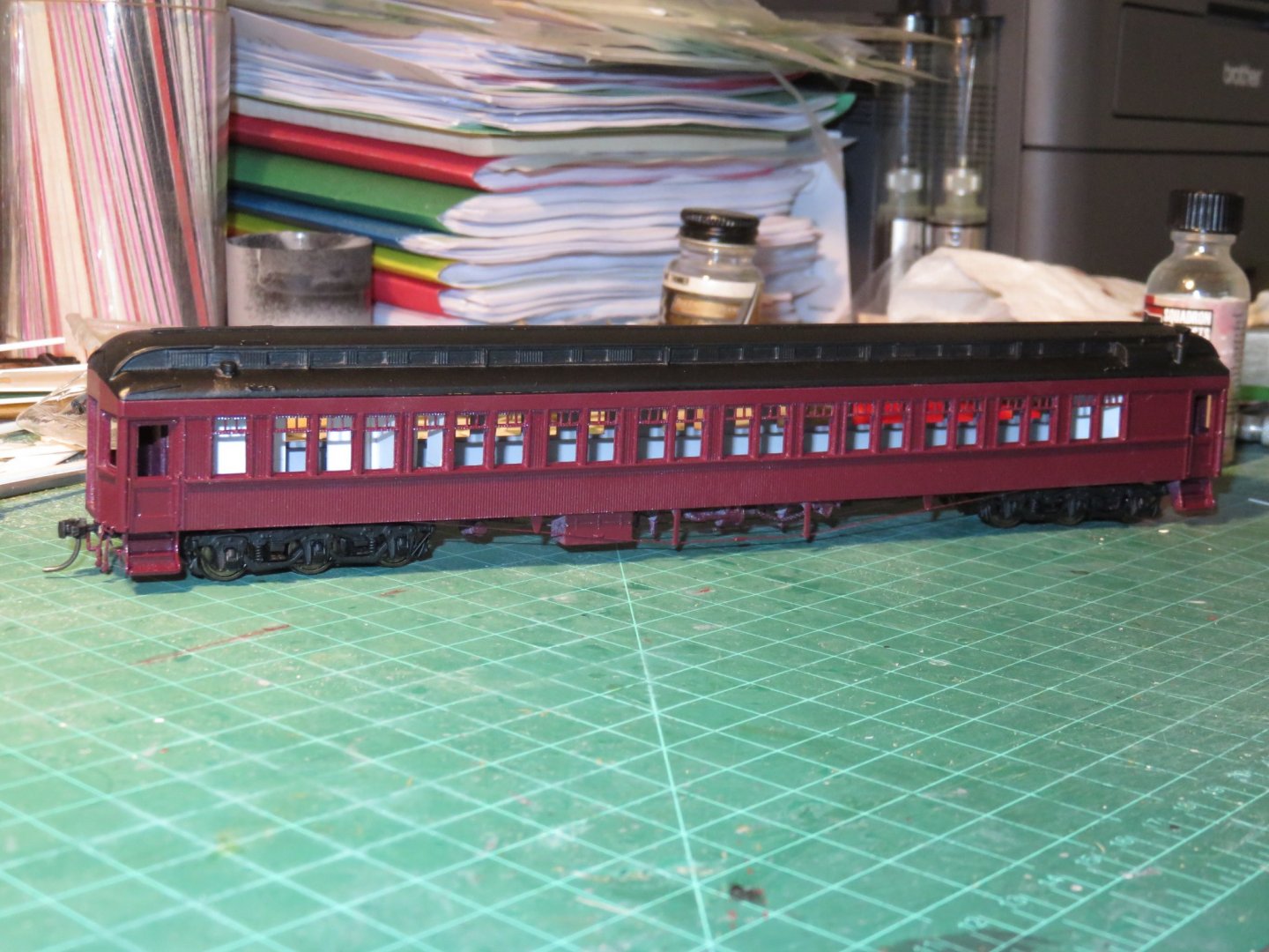
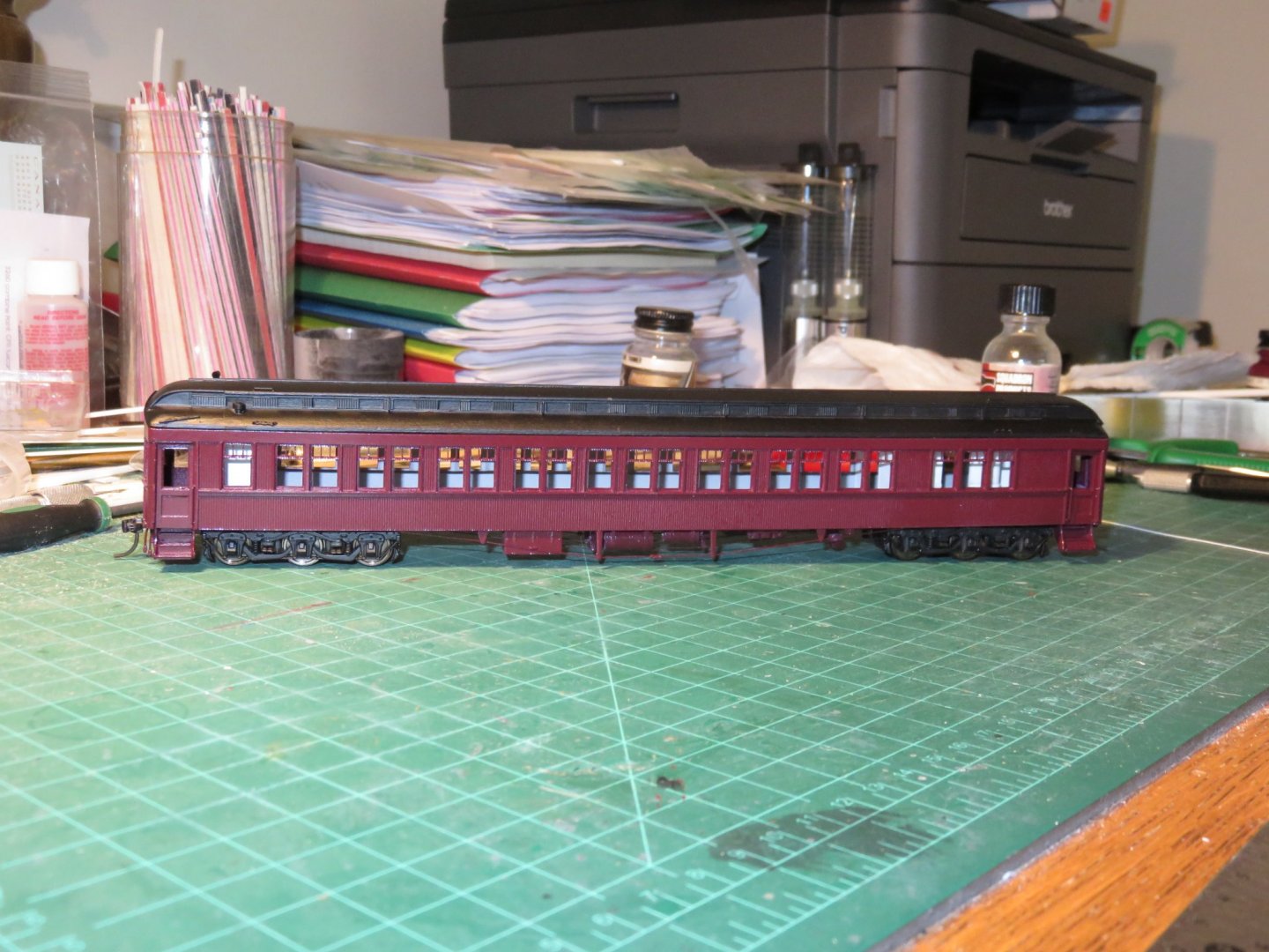
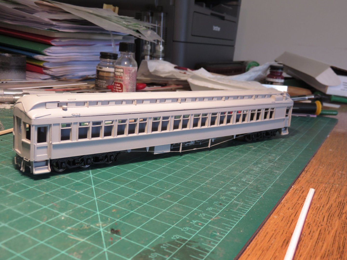
Over the last couple of days, I've managed a good bit of the painting, thanks to some better weather (although today is a literal washout). I should start off by mentioning that the primer was rattle can Tamiya grey surface primer, a nice go-to paint. I lack air brushing facilities in my house (something I hope to remedy in the future), so all of the car's exterior paintwork will be done by rattle can. Not the best, but I can make it work, but it means to avoid gassing myself out of the house, the majority of the painting must be done outside (fair weather only!). The CPR tuscan red is Scalecoat II lacquer. This can be a bit tricky to spray with a rattle can. I find the trick is to be moving fast (considerably faster than with other brands of rattle can or with an airbrush) to avoid heavy paint build-up and to keep the coats thin. The paint on the roof is a flat black from Tamiya. If the tuscan looks a bit speckly in places, it's due to the Scalecoat II being a gloss paint, which is great in that no gloss coat will be needed prior to doing the lettering, but it reflects the light from my flash. In person, it looks much better. Even though it's been a couple of days, I need to give it a bit more drying time before I tackle masking and painting the underframe. The interior will be done separately at a later point in time, once my seats have arrived and been assembled, so it still glares white behind the windows! Andy
- 154 replies
-
- 17
-
-
This is the diagram I was working from: So any additional info you’re able to dig up would be greatly appreciated! Andy
-
It could also be possibly due to an upgrade. From what I have read, the 1500 series coaches were built around 1907-1909, prior to the introduction of the UC braking system, but they would have had some kind of air brake system. The cars were subsequently rebuilt in 1912. That seems, to me, to be an unusually low number of years in service to require a rebuild (considering there seems to be no further record of major rebuilding until retirement around 1960), unless regulations required it for safety reasons (ie an upgrade in braking equipment). I wonder, though, if the retainer valve was required as an emergency back up. If you read the NMRA file, the UC system was designed to allow for a gradual release of air (and hence the brakes), as opposed to the AB and KC systems. If the UC system failed either due to mechanical fault or freezing, or if the locomotive was not equipped for passenger train service, or even if the coach was used in mixed train service, a retainer valve would be a fail safe backup. Andy
-
Some further digging, and it would appear that you are right. Contrary to what I had initially interpreted what I had read, passenger cars were equipped with retainer valves: Air brakes for model railroaders Andy
-
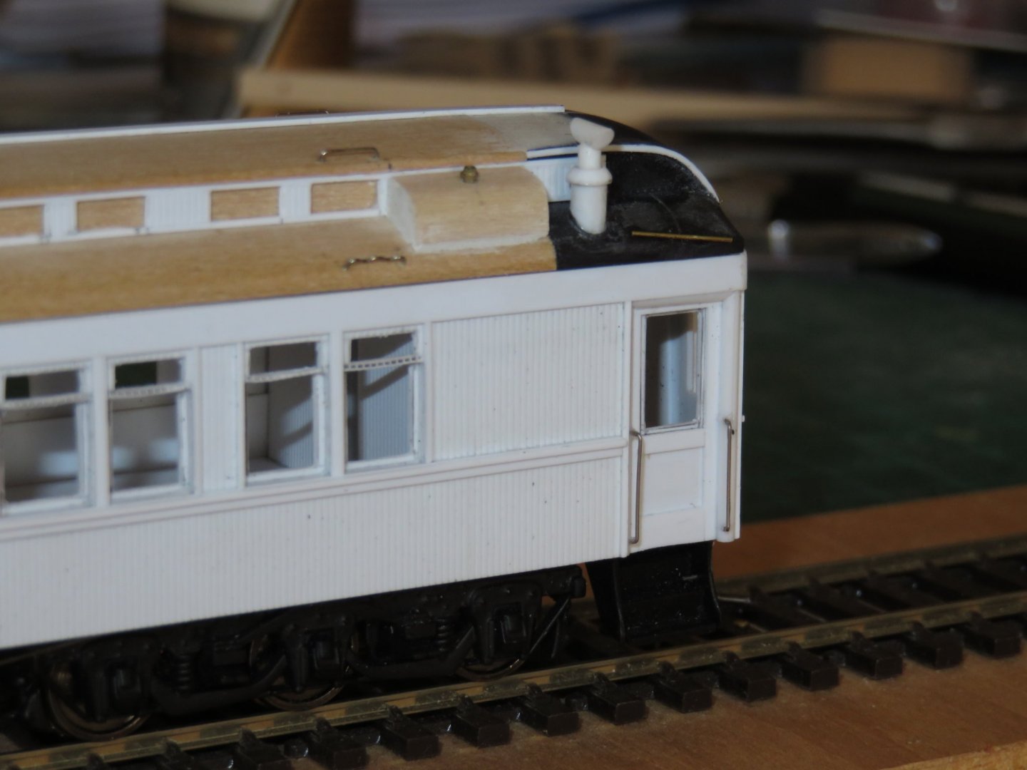
As always, I can't thank everyone enough for the kind comments, helpful suggestions and likes! Work is now complete on the window mullions (WHEW!). It was a slow and tedious process (I think I may have mentioned that before, sorry for the repetition), but it was well worth the effort. Definitely a detail that, had I omitted them, would have nagged at me, and it saves me from having to make repeated (embarrassing?) explanations as to why I left these features out, if I ever take this car to a prototype modellers meet. Painting has now resumed with a second coat of primer, and this morning the car got it's first coat of tuscan red (photos to follow soon). During the mullion interlude, I was also struggling with another detail that I had missed: If you notice in the photo above of another prototype car (I'm fairly certain this is an official car), above the window just below the roof overhang of the adjacent car, there is a small valve and some pipework. This feature seems to be present on most (if not all) CPR wooden cars, but I couldn't find photos indicating on which end it was supposed to be located on my car. Until recently, so it was added in the appropriate place: The valve itself is a brass casting meant for the drain valve of an air tank, but repurposed here, with some brass wire for the piping. I'm not entirely sure what the function of this valve is. If it was a freight car, I might assume it was a retainer valve. In a KC or AB freight car braking system, a retainer valve slowed the release of air from the car's brakes when descending a hill. These valves allowed the brakes to release gradually while the trainline could be replenished from the locomotive(s), and helped to keep the train in control when descending steep hills. Brakemen working from both ends of the train would have to manually adjust each retainer valve prior to the train beginning it's descent. In a UC passenger car braking system, this function was integrated into the UC control valve, and could be controlled automatically. This allowed passenger trains to operate without brakemen. Anyway, regardless of function, the valve is in it's proper position. Andy


- 154 replies
-
- 15
-
-
Pin driver
realworkingsailor replied to ErnieL's topic in Building, Framing, Planking and plating a ships hull and deck
I have a pair of spike insertion pliers that work brilliantly. Andy -
The tedious work of installing the mullions is progressing. There's decidedly a limit to how much I can do at one sitting (without going totally cross-eyed). I've just now completed one side of the car, and have started on the other side: With any luck I should be back to painting soon (after a brief stopover in "filler land" to fix the roof). Andy

- 154 replies
-
- 15
-
-
What a difference a small thing, like changing glue, can have on an outcome.... (Thanks, Druxey, for indirectly giving me the idea) Some progress on the mullions, as of this morning. Switching to CA glue has helped restore some of my sanity, or, at the very least, cleared the air of the loud blue fog that shrouded my previous attempts.... 10 mullions done... 76(?) more to go... I think.... Andy

- 154 replies
-
- 11
-
-
Hmm.... It’s a thought.... I may, however, first attempt a corollary of your theory and try using CA glue instead... I have some gel CA so that at least I may be able to better control where the glue ends up.... Thanks for the ideas! Andy
-
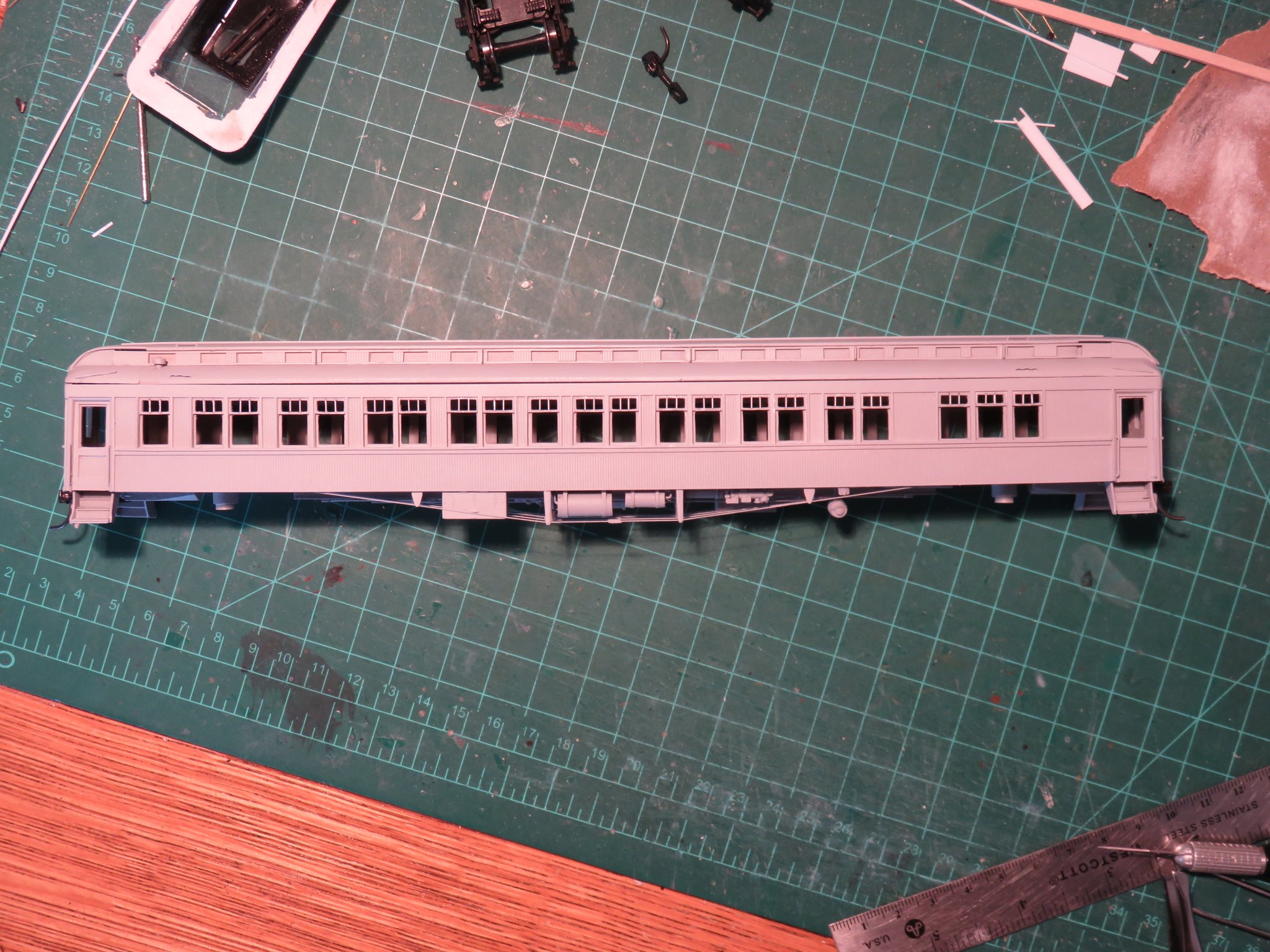
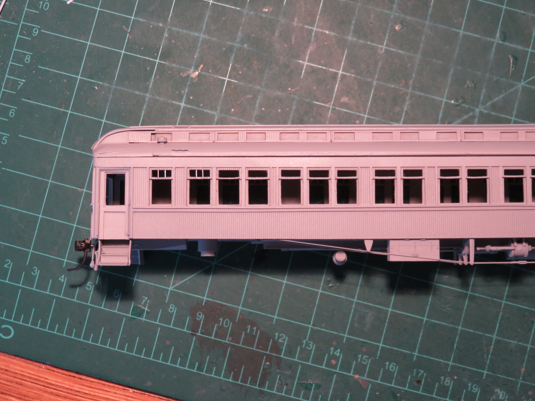
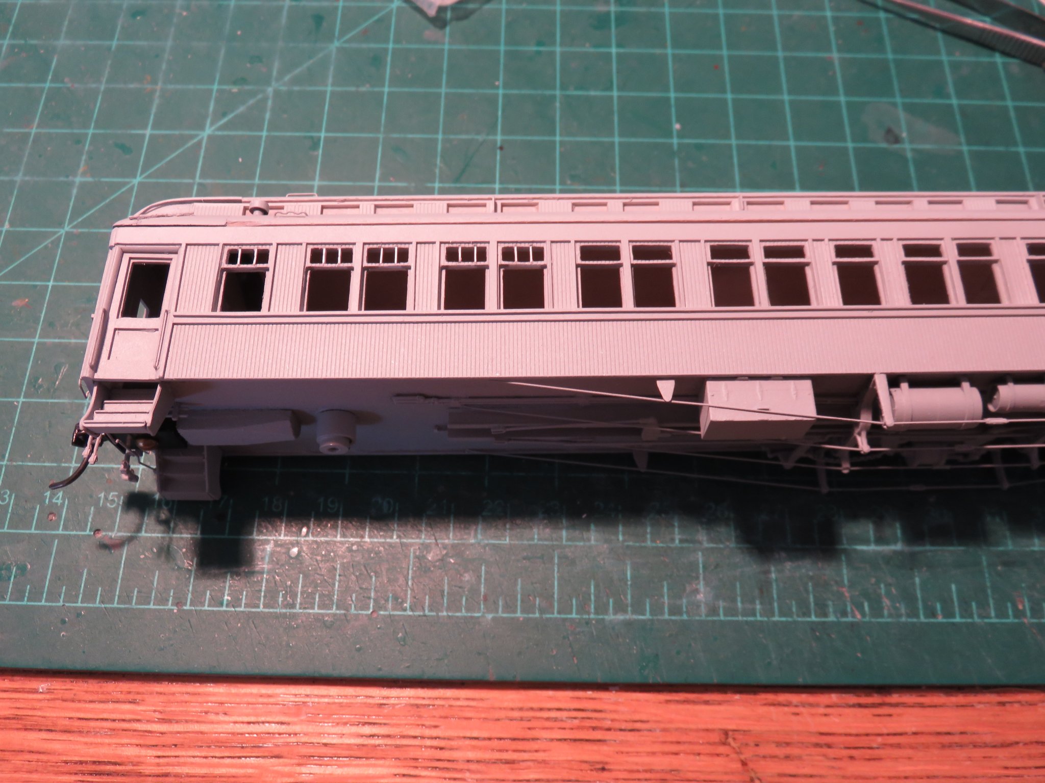
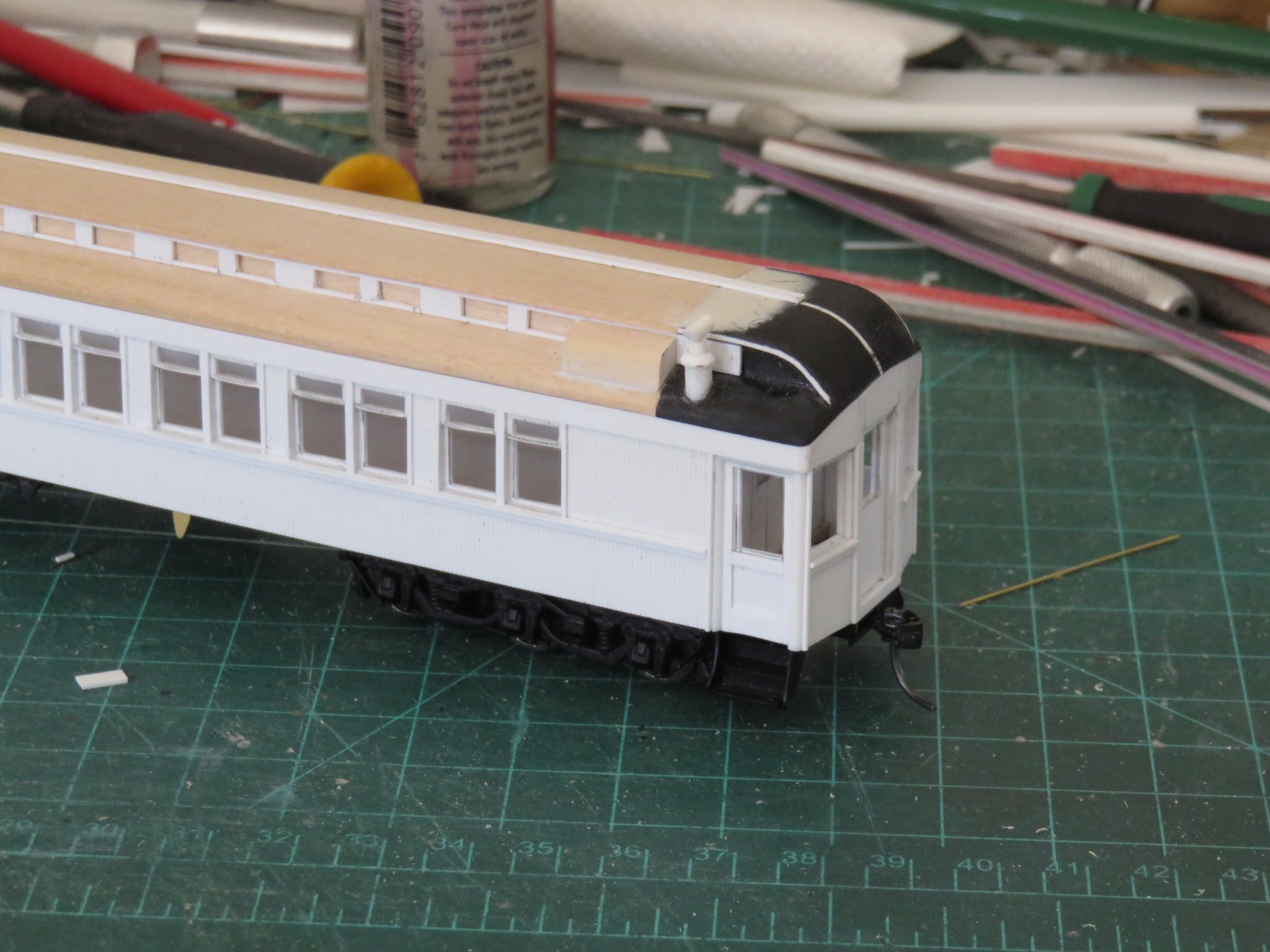
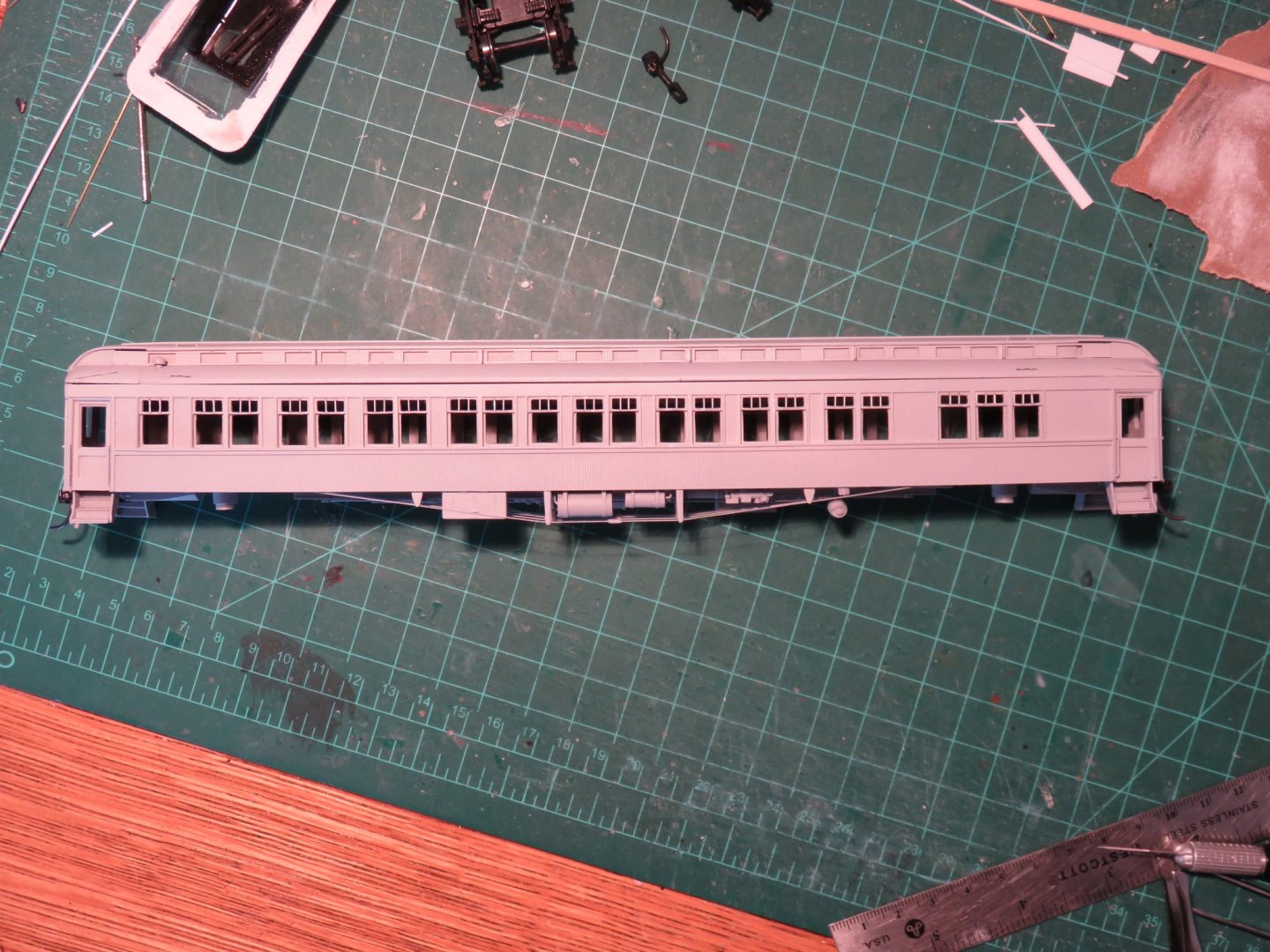
It's been a few days, but time for a small update. The plastic and paint I ordered has arrived... or, more accurately, I went to pick it up, as the paint (rattle cans) could not be shipped via the mail. (An hour and ten minute drive to the hobby shop, 30 seconds to pick up my order then another hour and ten minute drive home.... Isn't curbside wonderful!). I'm still waiting on the seating, but who knows when that will ever arrive. I've added the wind deflectors to the clerestory this morning, so that largely completes the car roof. Hooray! As for the window mullions.... where to even begin.... I think I scared the dog... she's not used to hearing anyone curse in full sentences. Suffice it to say that it was an exceedingly frustrating endeavour. 0.010" x 0.030" styrene was needed to make the mullions (any thicker and they would have looked clunky). Unfortunately any time I applied glue (styrene cement), the little fleck of plastic decided it preferred to stick to the metal tweezers and not the adjacent plastic (or, conversely, go flying into the great beyond)... grrr.... After a few attempts I tried a slightly different approach by taking some 0.020" x 0.030" strip to use as a base and glueing the mullions to that first. The plan being to then cut out the division between the main and transom windows and inserting the entire construction into place... That strategy was binned quickly, when the styrene decided to glue itself to the cutting mat... and the metal tweezers.. and whatever it is in the great beyond that was far more attractive (What. The. Ahem!). So I've decided that for the sake of my sanity, I will forego the mullions. Not my preferred outcome, but... The first coat of primer has been applied now, so no more pictures of blinding white plastic, although some of the details still struggle to be seen.... And the opposite side of the car... looks like I need a bit of filler on the eave of the roof over the lavatory windows. No big deal, at least things have resumed their forward movement! Andy

- 154 replies
-
- 15
-
-
Hi Kevin, nice job! Regarding your lights, the following was copied from the International Regulations for the Prevention of Collisions at Sea: Rule 26 Fishing Vessels (a) A vessel engaged in fishing, whether underway or at anchor, shall exhibit only the lights and shapes prescribed in this Rule. (b) A vessel when engaged in trawling, by which is meant the dragging through the water of a dredge net or other apparatus used as a fishing appliance, shall exhibit: (i) two all-round lights in a vertical line, the upper being green and the lower white, or a shape consisting of two cones with their apexes together in a vertical line one above the other, (ii) a masthead light abaft of and higher than the all-round green light; a vessel of less than 50 metres in length shall not be obliged to exhibit such a light but may do so, (iii) when making way through the water, in addition to the lights prescribed in this paragraph, sidelights and a sternlight. Hope that helps! Andy
- 337 replies
-
- 4
-
-
- finished
- mountfleet models
- (and 1 more)
-
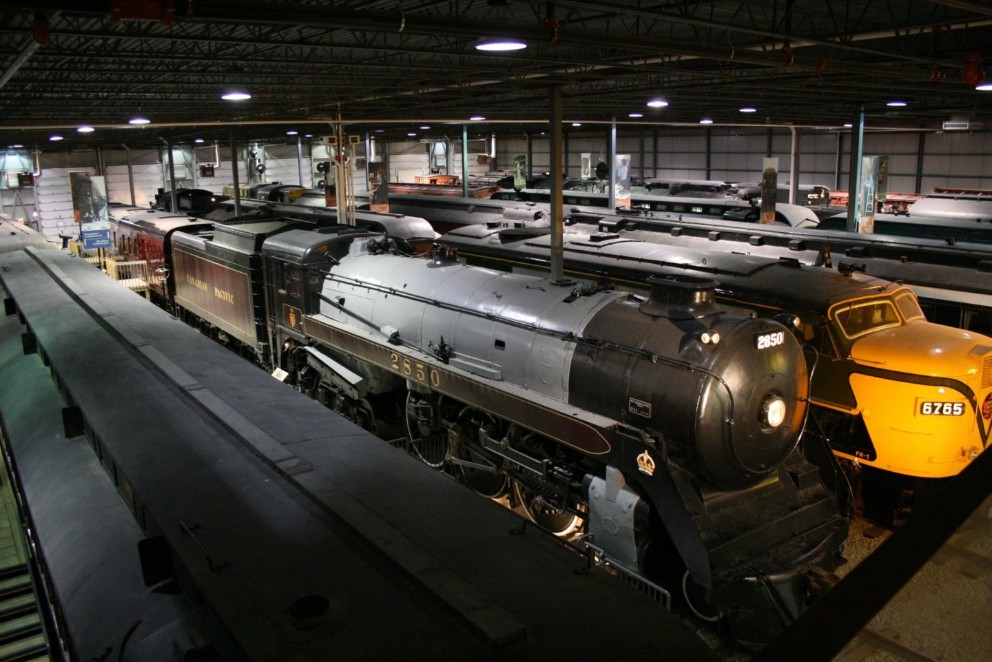
The DAR was a bit more of a secondary/regional/branch line all wrapped in to one. One of the last lines in North America to run trains with open observation cars (even wooden obs cars as late as ‘56). The big freight was gypsum, complete with double headed ten-wheelers and strings of oversized composite, drop-bottom gons (the “famous” Big Otis cars). There’s a great online resource here, lots of photos and other documents. Personally, one of my favourite aspects of the DAR was how they painted (and named!) their steam engines: http://dardpi.ca/wiki/images/DAR2552_Halifax_1939.jpeg Andy
-
A little bit more into the late ‘40s, early ‘50s. I’m in the planning stages of a layout representing portions of the Dominion Atlantic Railway, a CPR subsidiary, in Nova Scotia. Andy
-
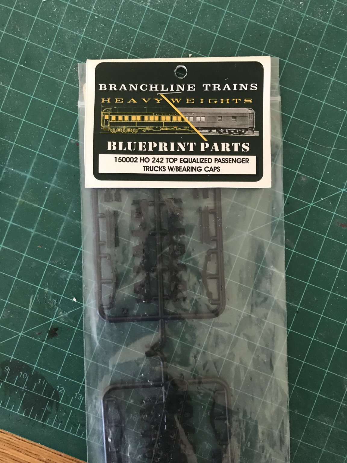
Hi Ernie, thanks for the compliments! I agree the Branchline kits were reasonably close (albeit a tad short) for a CPR heavyweight. Would it rot your socks to know that Branchline also made a top-equalized truck too? 😏 I’ve had these kicking around for a few years, but apparently Bethlehem Car Works has them listed for sale: https://bethlehemcarworks.com/branchline-passanger-car-parts/ Andy

-
Just got notification that my order from Walthers has shipped (the seats)... coming from Milwaukee.... I wonder how many exotic locations it will pass through before getting to me.... and will it arrive before.... say.... September (year not specified)... Fingers crossed!🤞 Andy
-
Well, the orders have been made... The seats from Walthers, and the styrene (and some paint) from a local(ish) hobby store. Paint and plastic should be here early next week.... still waiting on news of the seating.... Andy
-
Although I’ve made my own grabs in the past, these were all pre-made. (I cheated, sorry😔). There’s not many parts suppliers left anymore, and most that remain viable seem to stick to locomotive parts or building parts.... Andy Edit mwahaha: https://www.walthers.com/coach-seats-for-standard-gauge-cars-drgw-style-w-two-wood-ends-pkg-12
-
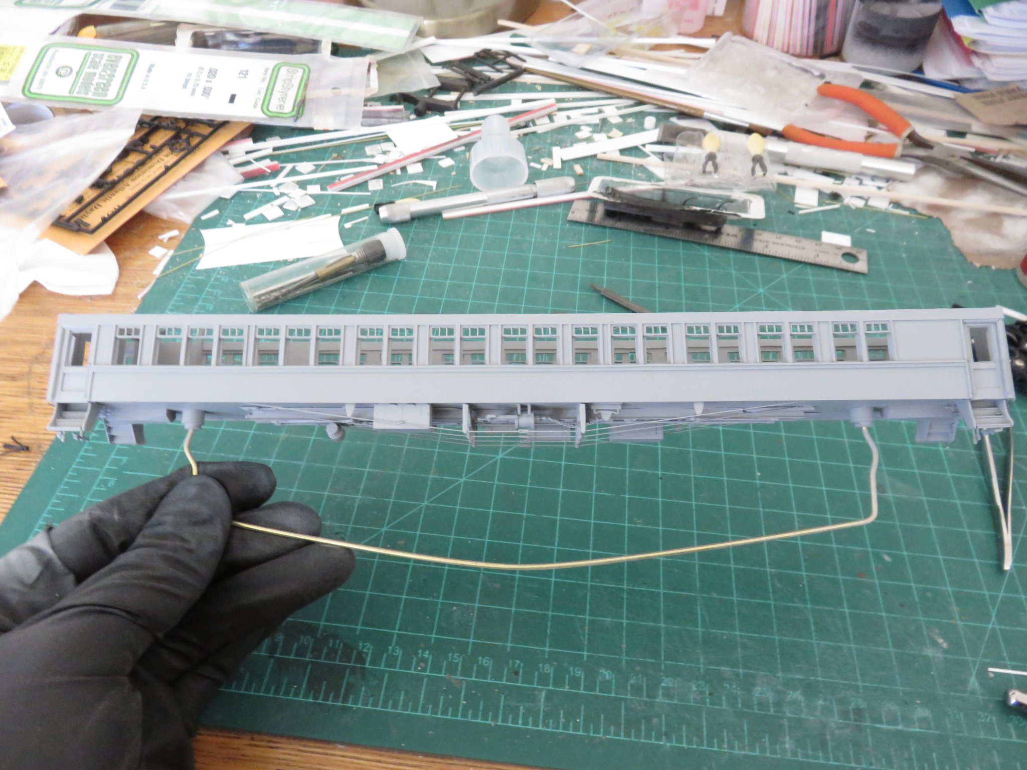
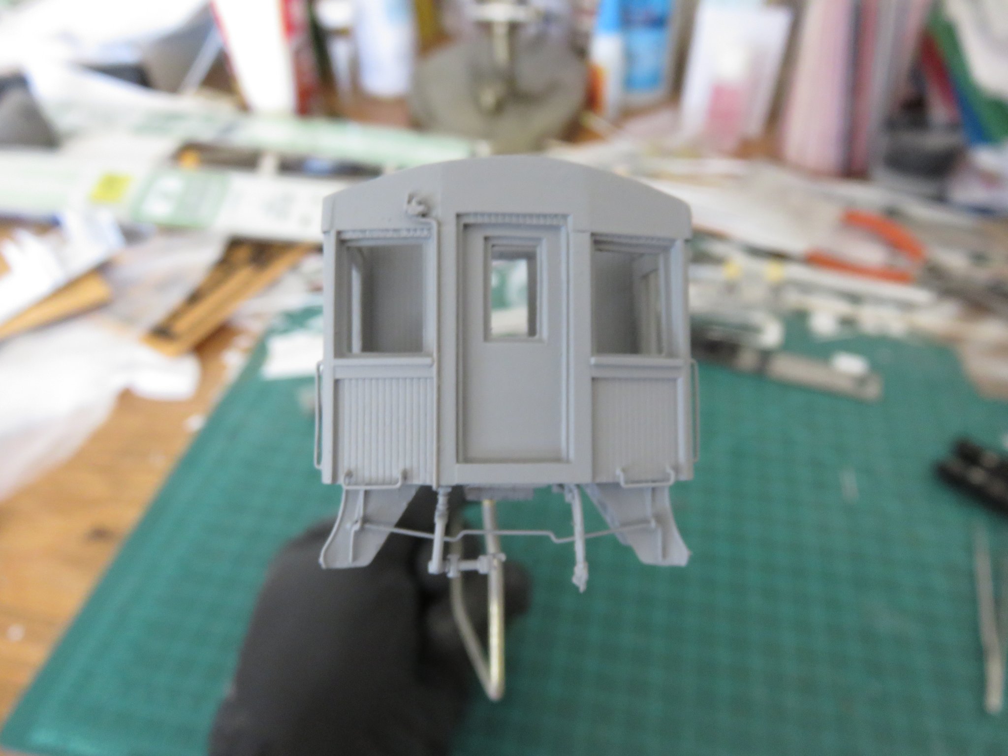
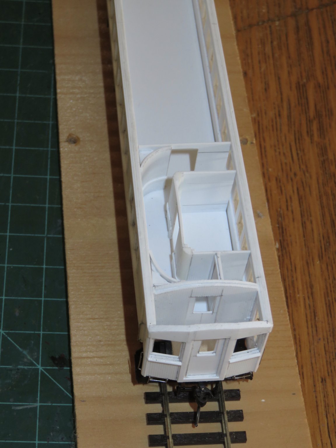
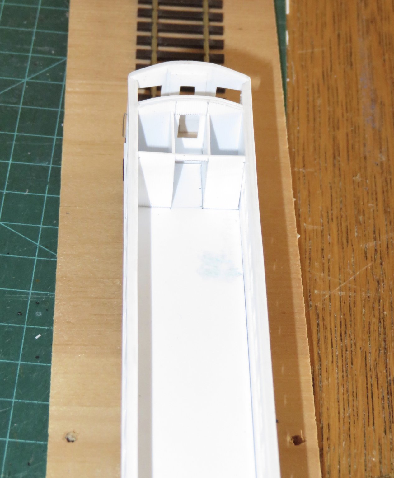
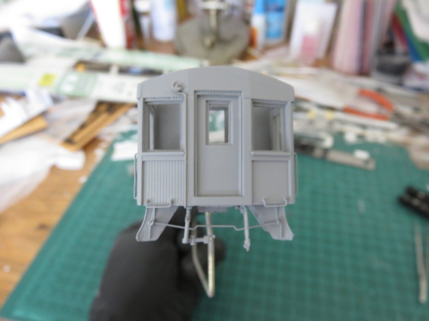
Thanks everyone for the comments and the likes! I have been slowly working away on my coach build. I've now made up the interior bulkheads and partitions. Most of these areas will really not be seen after the model is complete so I've kept the details rather basic. I still intend to add seating and the requisite features in the lavatories. The smoking room end of the car. Getting the 0.030" styrene to curve that tight and stay without springing back was fun. I simply used the handle of one of my files as a mandrel and gently and repeatedly worked the styrene until it held its shape. After glueing the panels to the floor, I then added some gussets to help hold everything in one place, and give it some structural strength. The interior is still removable at this point (and I'll probably keep it that way). The opposite end of the car was much simpler to construct, with only the women's lavatory and the heater room to contend with. After the interior, it was time to get after the grabs and gutter details. I find grab irons to be one of the more tedious parts of any railway rolling stock model build. Very easy to mess up, very hard to undo is there is an error, but absolutely essential for any finished car. Each end of the car has two drop grabs, plus the entry handles on each side. Up on the roof there are eight more, four located on top of the clerestory and the wavy looking grab, just above the eave, is the ladder rest. Also on each end is a peaked gutter above the end door, and a sloped gutter above the entry door. This were formed using brass wire. The grab irons where salvaged from my parts bin (leftovers from old Walthers passenger cars) and are made of stainless steel wire. I've also almost completed the other end details. You can see the coupler cut-lever attached to the entry step as well as the hose ends for the steam, air and signal lines (the one is slightly obscured by the coupler head). Finally, I've added the fill cap to the Baker heater header tank. I made this from a Precision Scale Co. (PSC) 0.030" pipe union brass casting. At this point I'm getting closer to finishing the model, all that really remains now are seats and a few final details such as the window mullions and the air deflectors for the clerestory. I'm going to have to put in an order this week for the styrene strip that I need. I also need to order seats, but the problem lies in getting the right kind. The few suppliers there are make seats for later streamlined cars. I have yet to find anyone who makes the old fashioned "walk-over" seats (seats that could be made to face either end of the car by "walking over" the seat back from one side of the seat bench to the other) appropriate for cars of this era. Andy


- 154 replies
-
- 15
-
-
I would say it’s very likely a wind scoop of some kind, but definitely much simpler than the Garland type. From what I can see it’s a piece of metal, simply flanged to the clerestory. Andy
-
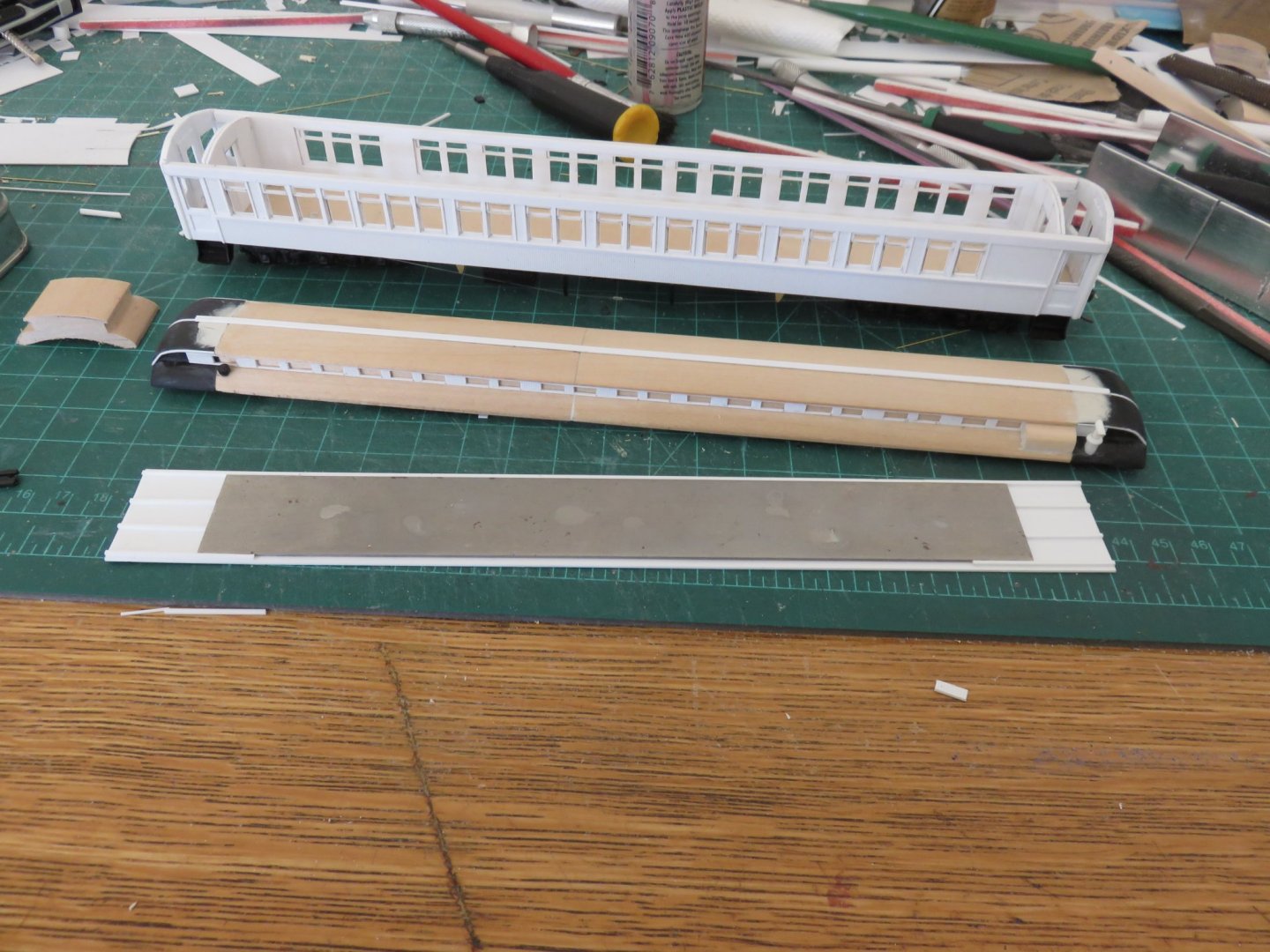
Thanks, again, everyone for the kind comments and likes! Work has been progressing smoothly over the last few days. The major joints in the roof have been filled and sanded smooth, as and where required. I use Squadron putty, as it bonds well with styrene. It's not quite as good with wood, but if you're careful it will do the job there too. A few extra strips of 0.020" square stock were required to widen out the edges of the roof ends to match the wooden centre section. I've successfully managed to make the two clerestory inserts. The include all the vent openings, however I was unable to locate the aluminium mesh (that I know I have somewhere, hidden), so they will remain as just openings. This is probably for the good, as the material thickness wouldn't allow for another layer anyway. The lavatory vents were also added (again, spare parts from a Branchline kit) The I've also completed the visible components of the Baker car heater; the smoke jack and the covered header tank. The smoke jack was simply made using various thicknesses of styrene tubing. The header tank was made from a strip of scale 12" x 24" basswood. The ends were treated with Squadron putty to fill in the end grain of the wood. All that needs to be added is the fill cap. Finally the roof top conduit cover was added using a strip of 0.020" x 0.080" styrene. You can clearly see the conduit running down the centre of the car roof in the photo above. Originally these cars would have been lit with Pintsch gas, and would have had a series of round vents running the length of the car (you can actually see them on the rood of the baggage car in the extreme left of the photo. When the cars were converted to electric light, the wiring followed the same path as the gas lines (I would imagine, mainly, to avoid having to tear out sections of the interior to install the wiring and to avoid having unsightly wires dangling around). You can also notice some odd pieces sticking out from the clerestory (towards the bottom left of the photo). I'm not entirely sure of their function, or construction, so for the time being, I will omit them (I may circle around to them later if I manage to find more information). Diverting my attention to the interior, I've added a steel weight to the bottom of the floor. And I've mapped out the interior partitions for the smoking room and the lavatories, lockers etc. The outline is just the basic floor plan, when built, all the corners will be rounded off or coved. I will likely keep this section removable to allow ease of painting. Next up in the construction sequence will be to finish the interior construction, and then my "favourite" task(s); grab irons and end details. I haven't forgotten the transom window mullions either, but I've determined that I need some thinner stock styrene than I have on hand, so I'll have to put in an order with the hobby shop. I just need to work out a list of other items that I may "need" (one package of styrene seems a tad frivolous!). Andy


- 154 replies
-
- 18
-