


DanielD
-
Posts
541 -
Joined
-
Last visited
Content Type
Profiles
Forums
Gallery
Events
Posts posted by DanielD
-
-
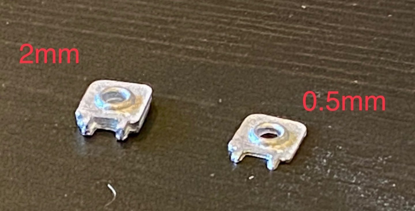
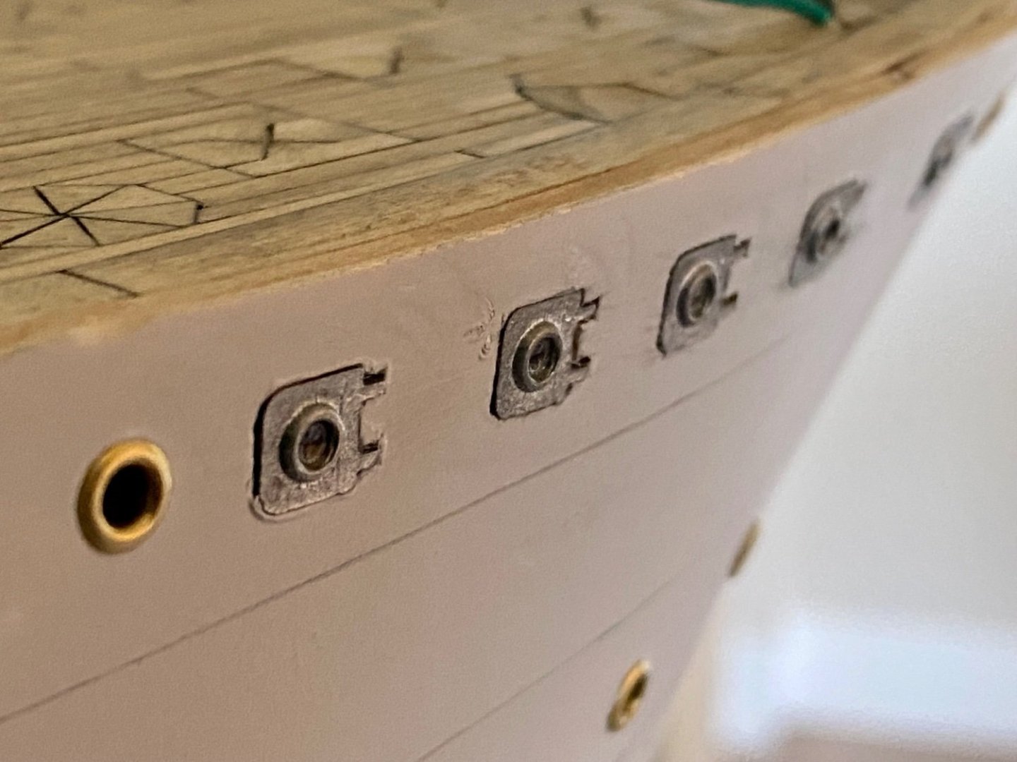
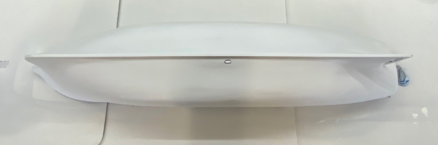
One problem I encountered when installing the “square” portholes is getting them to sit flush with the side of the ship. As you can see from an image blow up, these portholes should be flush, but the kit supplied metal pieces are instructed to be just be stuck to the side. However, the initial pieces are 2mm thick and just didn’t look good sitting on the surface of the hull, and I wanted them to light up along with the other portholes. I ended up grinding each tiny piece down to 0.5mm thick, then carving into the 0.5mm second planking so they inset into the hull to get a nearly flush detail look.
-
Good weekend mates, I just realized that it’s been a while since my last update, but we have been busy with outside projects. Regardless, I’m still making some progress on the AV.
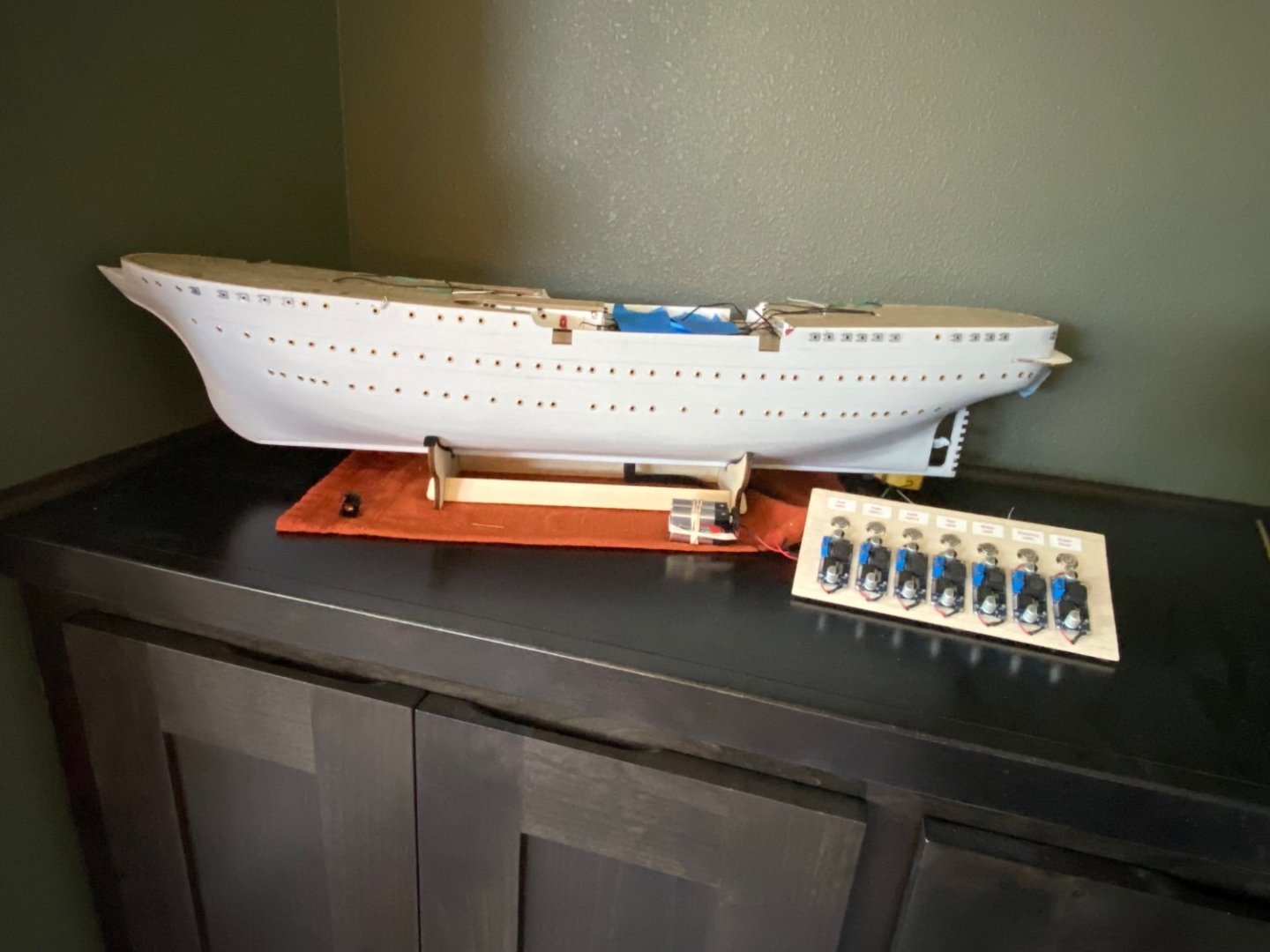
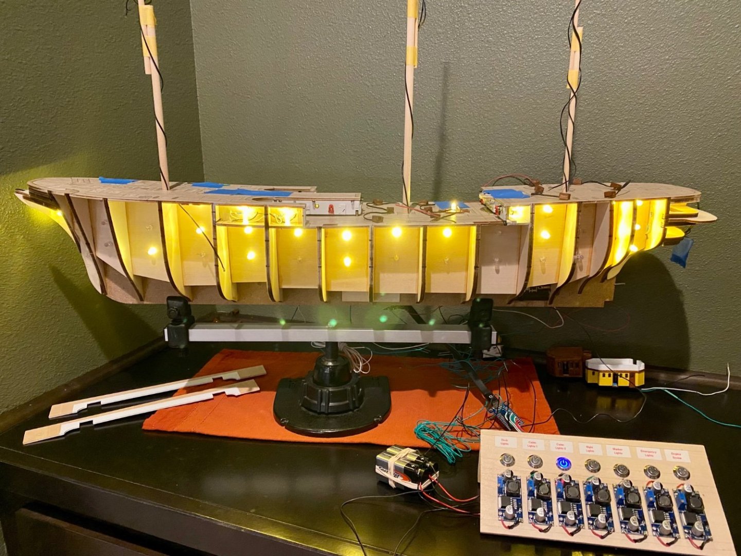
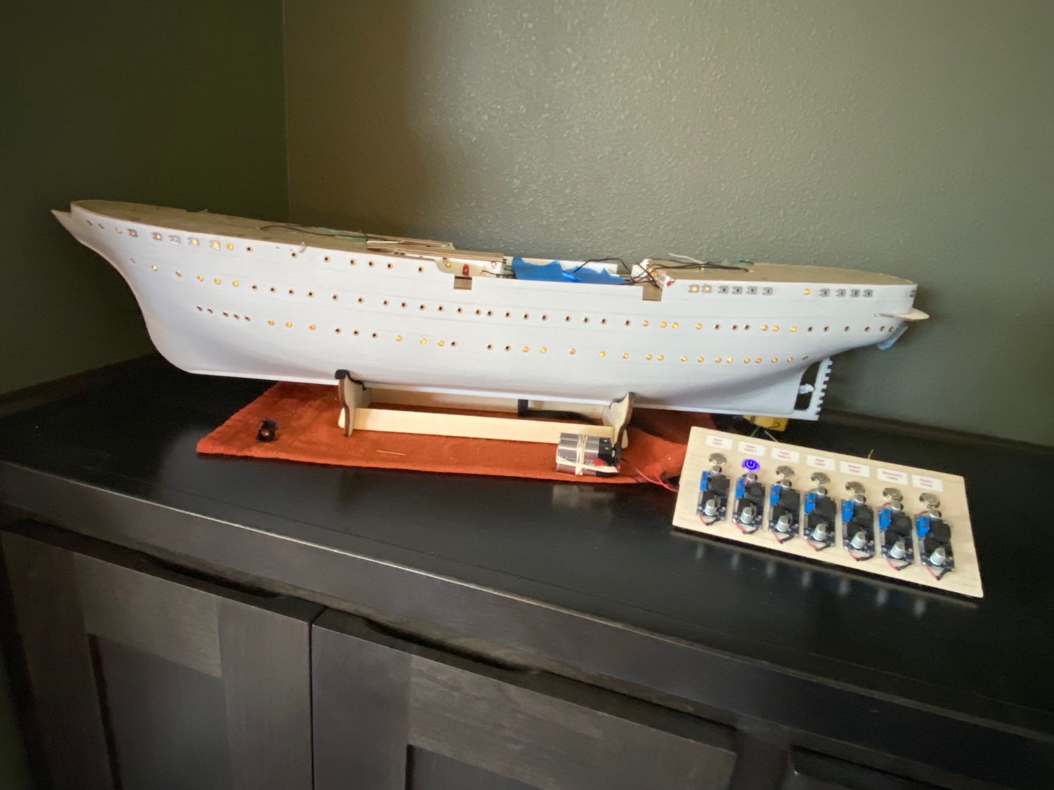
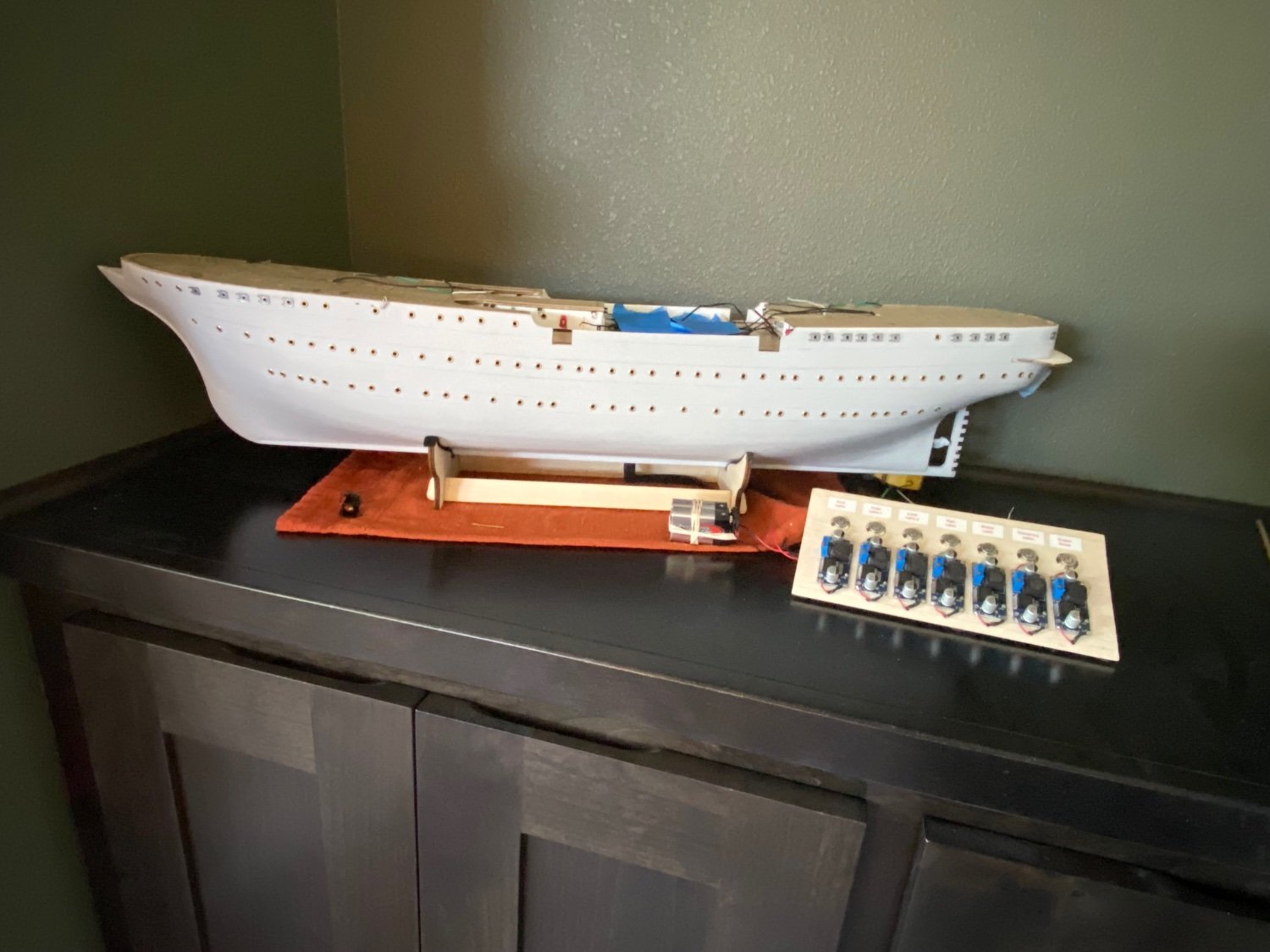
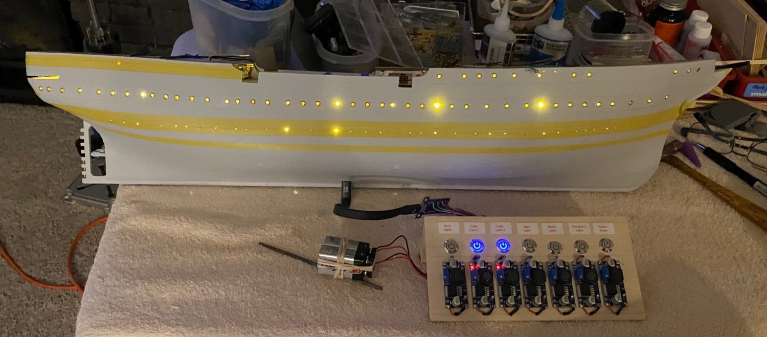
In this update, I have completed installing all the port holes, both the round and square versions, and happy to report that I have been able to get the lighting to work on all except one porthole on each side at the bow which is directly over a large area of bow support, so no lighting in that area. Still, I’m very pleased with the outcome.
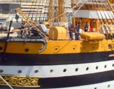
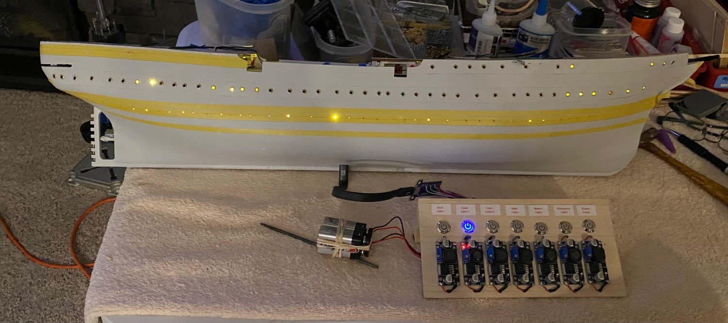
Quick refresher, the goal of my porthole lighting is to simulate a real life night scenario (first image), where not all the portholes are lit at the same time. I have two versions of lighted portholes, which I can have one or the other set lit, or can have both on which lights all of the portholes.


- Dave_E, king derelict, VitusBering and 1 other
-
 4
4
-
1 hour ago, Mike Dowling said:
Nice job with the hull finish. Did you use the template for the portholes or did you measure them? I found that I had to measure them all.
Hi Mike, the instructions are indeed a little vague. The one image that shows a 20mm spacing could imply 20mm between each port hole, but according to the 1:1 drawing, the spacing is not equal the entire length of the ship. So, like you, I measured each one from a zero reference point. I picked the left most port hole on the bow 1:1 drawing as my zero point, then measured each hole from there. I have the bottom row of port holes to finish later tonight, then see what I can do about the square openings. I want to inset the metal piece that came with the kit so that it is basically flush with the hull, or maybe be extended 1/2 mm like the brass fittings that act as port holes. Ideally, both the port holes and the square hatches should be flush with the hull, but I'm not getting nice clean holes so the brass grommet is needed.
Once I have all the port holes fitted, I'll prime everything one more time, the paint the entire hull white, let dry, mask off the white stripes, pain everything black, let dry, mask off everything except the yellow/gold and paint that, lastly masking off everything except the green bottom. There have been a couple of painting schemes over the years with a red bottom, a black bottom and a dark green. I like the green, so that is what I have planned.
- Dave_E and Mike Dowling
-
2
-
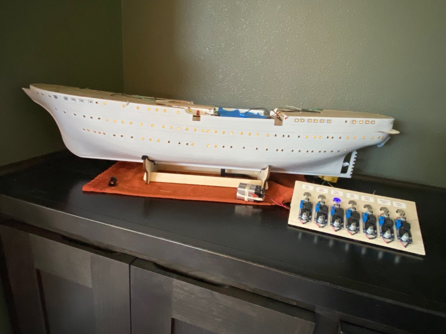
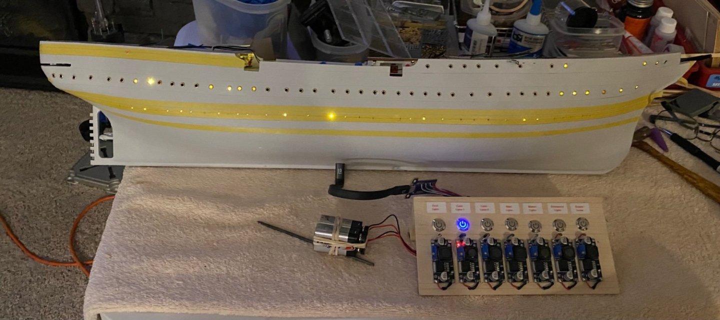
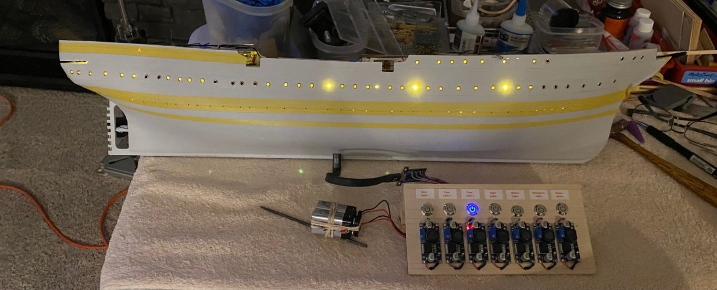
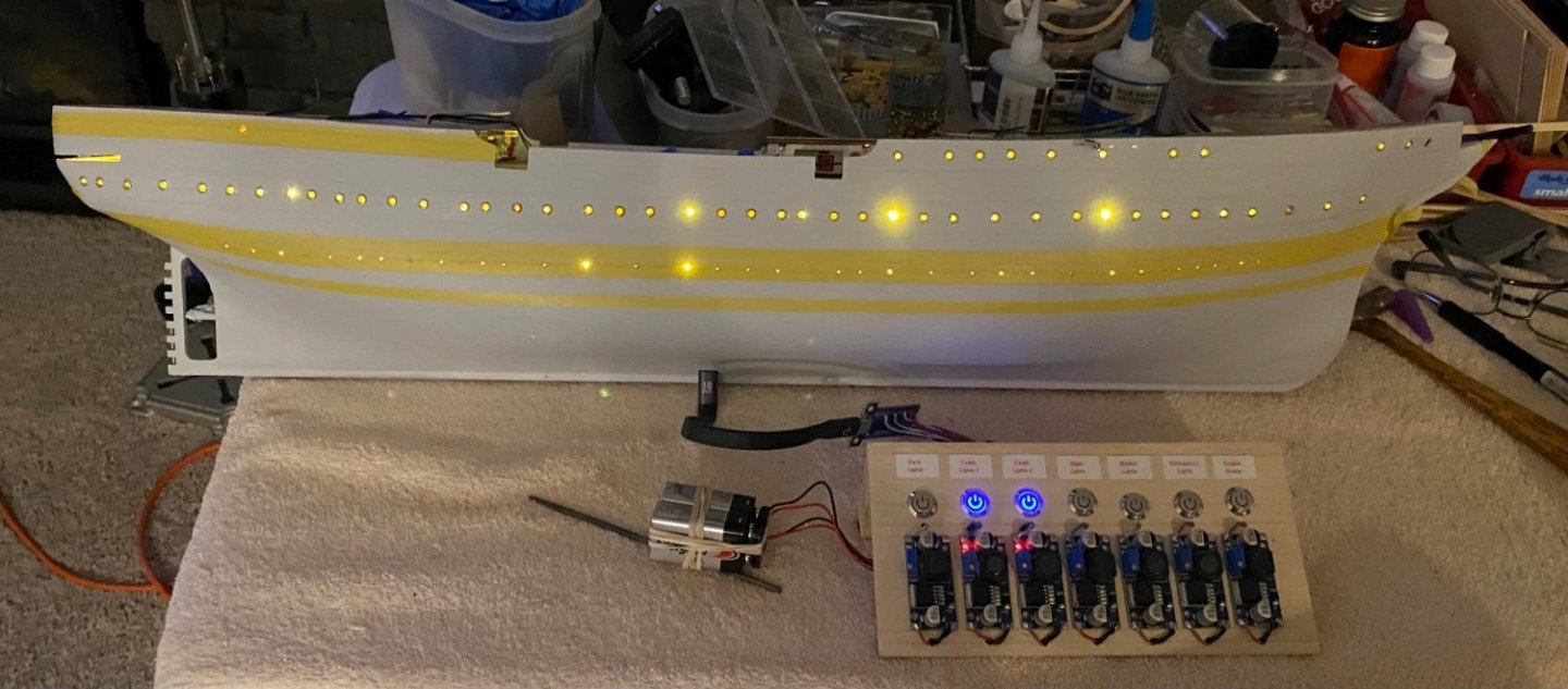
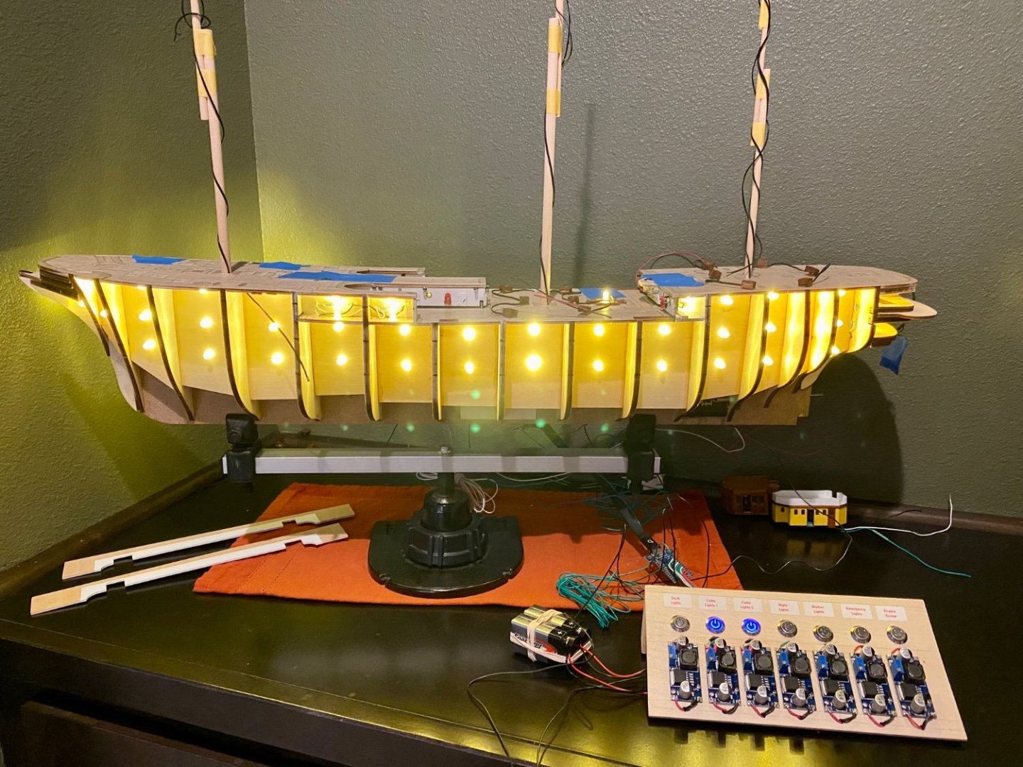
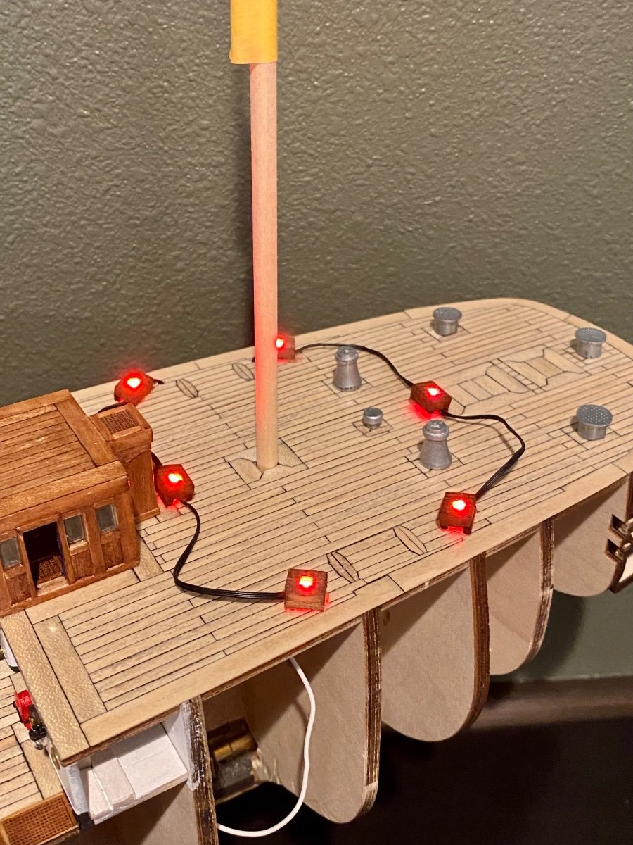
Good evening mates, time for another update. Today, working on the starboard port holes and learning that all the planning in the lighting seems to be working. There are three settings for the port hole lighting, 1) some portholes lit, 2) the opposite portholes lit, and 3) all on. The images below show the plan come to fruition.
- clearway, Mike Dowling, hof00 and 2 others
-
5
-
Good afternoon mates, todays update is sponsored by…sorry, got carried away. I was able to finish the second planking, fill most of the seams and wood grain, and have the primer/sealer airbrushed on. Now have to let sit for 24 hours or so to let primer cure. But progress is progress.

- Dave_E, king derelict, Mike Dowling and 2 others
-
3
-
 2
2
-
-
-
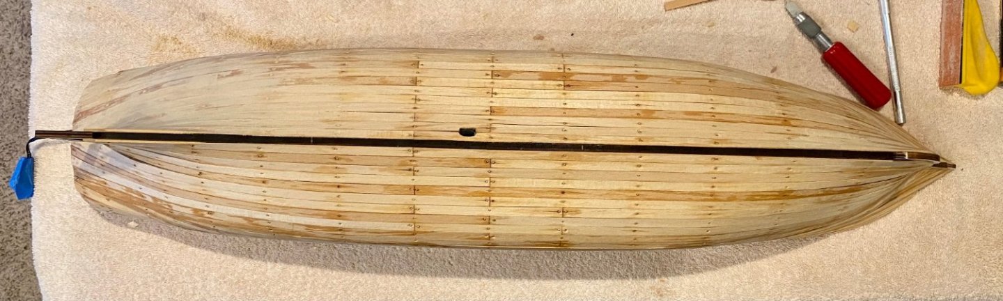
Good evening mates, time for another hull update. I have to say I have discovered my favorite way to adhere the second layer of planking! Okay, I didn’t”discover” this method, but it is the first time I have used it, and might I say it was glorious. The method I’m speaking of is what OcCre calls for in the instructions, using contact cement. Using this method one applies the rubber like glue to both surfaces, wait until it dries, then press the two pieces together with pressure for an immediate permanent adhesion. What I loved about contact cement, it was not messy, was dry while I set the pieces in place and was quick (immediate) adhesion, like CA glue without the mess. What I didn’t like was the smell. The admiral sent me to the garage for this task with the outside door open, you know, good ventilation per the instructions. I’m very pleased with the results.
Only the starboard side done, but good progress.
- Dave_E, Mike Dowling, hof00 and 2 others
-
5
-
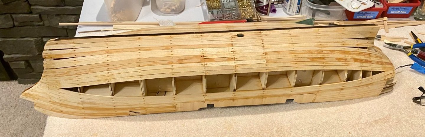
Good evening mates, another hull update. I have finished the first planking layer, sanded, filled some cracks, sanded again and now it’s ready for the second and final plank layer. After all the pounding, gluing, and sanding, I’m happy to report that all the electrical still works! Now to figure out the best adhesive to adhere the thin planks. I have used PVA and CA glue in the past. Both are messy. The PVA glue is more wet and warps the thin planks and is fairly slow drying so slow progress with the time I have to work on project. CA glue is fast, but makes the wood hard and difficult to sand and in this case I need to sand, fill, and repeat until very smooth to simulate a metal finish.. The instructions call for contact cement. Coat the hull and a few planks, let dry, and press into place for a permanent adhesion. I’ve never tried this method…anyone have experience with this contact cement? Clearway suggested Evo-stick fast setting wood glue, which may work, but still takes an hour ish to set and I only have an hour or so a few nights a week to work in the ship yard, so this might be too slow to make good progress. Other ideas appreciated.

- Knocklouder, Kevin, VitusBering and 5 others
-
8
-
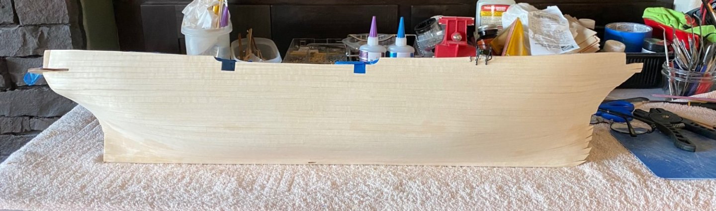
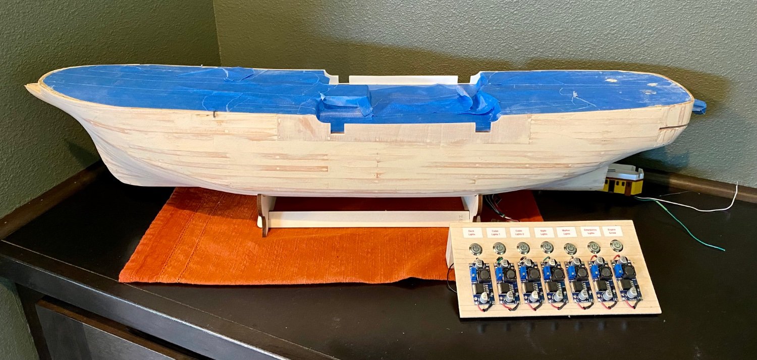
Good evening mates, another hull update. I have the main hull first planking basically finished with a few angled planks to manufacture and set, but the hard part is finished.
- Dave_E, Mike Dowling, clearway and 1 other
-
4
-
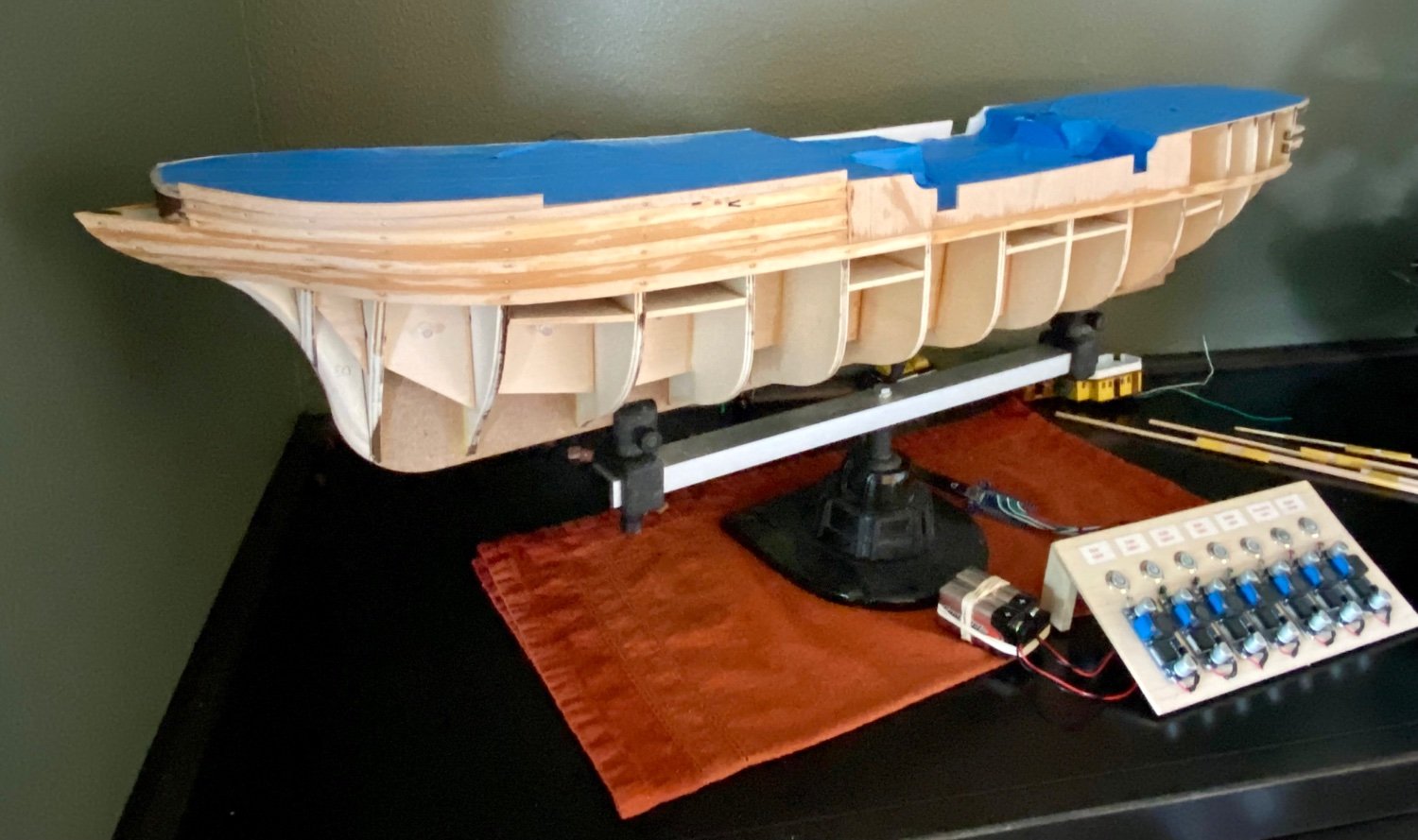
Good evening everyone, time for another update. Still working on the first planking layer, but working both sides equally to prevent hull warping.
If you look closely, you can see the USB-C plug to get power on board for all the lighting and motor.
- hof00, Dave_E, VitusBering and 3 others
-
6
-
6 hours ago, clearway said:
I was wondering how much of the work so far was removeable for when the planking started 😜. Are you going to use the occre supplied second planking or replace it Daniel?
Keith
Hi Keith, good to hear from you. I do plan to use the kit supplies second planking as the Amerigo Vespucci is a metal hulled ship so the quality of wood I use is not critical. I will have to fill in any imperfections and sand very smooth and paint with filler primer, sand again, paint again, then add the detail rivets and supports all before final paint. A slow process for sure.
Daniel
- Dave_E, king derelict and clearway
-
3
-
-
3 hours ago, VitusBering said:
Daniel, have you made any provision (or plan to do so) for access to the LEDs after the model is finished?
I know the LEDs have a very long life expectancy but they have been known to fail.
In my own very rudimentary lighting scheme I have (so far) tried to maintain access (the deckhouse roofs are not glued in, same for the nav lighting mounts) but it is becoming more difficult. I am not sure it is worth the hassle.
VitusBering, that is a very good question and the answer is yes/no. Let me explain, (No) I am not planning on having any capability to replace a LED. But, (Yes) 1) I am taking steps to protect the LEDs by making sure they all are matched with resisters to protect from overloading the LED, 2) I am running less voltage and thus leas than the maximum current so LED is not likely to fail, and 3) I am using voltage regulators that relatively slowly go from zero to maximum set voltage so as to not shock the LED.
Basically, I should get 30+ years or more out of the lighting based on how often I will actually have the display on. If a LED goes out, I can evaluate based on location if it’s even worth it to fix. For example, the night up lighting is important for the look of the ship (the green, white, red look of the Italian flag) and those are easy to access and replace. The LEDs inside the structures or in the hull, I doubt if anyone besides me will notice.
- VitusBering, hof00, Dave_E and 1 other
-
4
-
14 hours ago, Mike Dowling said:
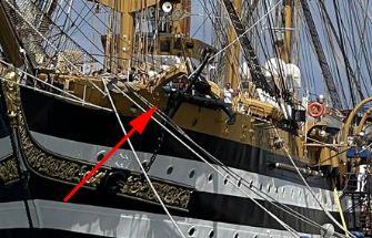
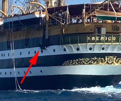
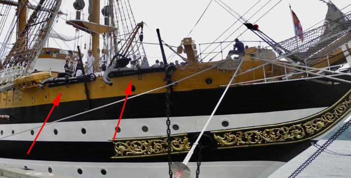
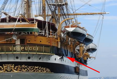
A puzzle for you! You mentioned a while ago about the AV having three anchors. The Occre kit provides 6 including 2 which are supposed to be fastened to the rear of the ship. I have scoured the photos etc of the real AV and it may be that there are 2 at the stern and I can only see 2 at the bow. What do you think is right?
Mike, at the time, I was talking about the bow anchors. Indeed the AV has 3 bow anchors, one on the port side and two on the starboard. In addition, the AV also has one anchor on either side of the stern for a total of five. Here are the pictures that I quickly found that show all of them.
- clearway, VitusBering, Mike Dowling and 1 other
-
4
-
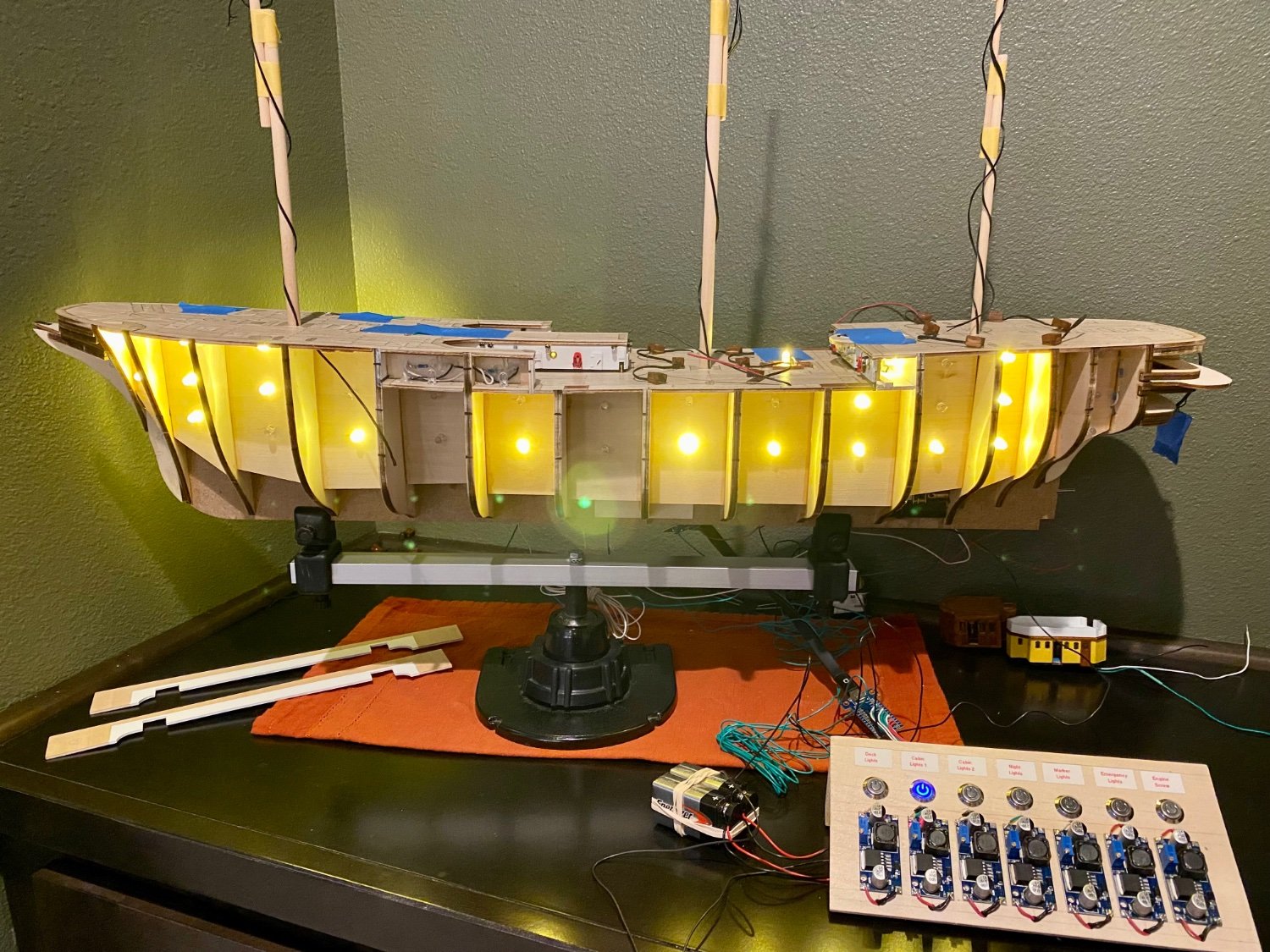
Good evening mates, it’s been awhile since my last post, not because I haven’t been working on the AV, but because what I’ve been working on is not visual progress. I’ve been working on the last major lighting project that I have planned for my Amerigo Vespucci, the port hole lighting.
My goal is to attempt to light the lower decks similar to what occurs in real life, meaning, not all the lower deck lights will be on at the same time (see image below). My plan is to light two sets of port holes. I can have one set on, or the second set, or if I choose, both sets which will light all of the port holes.
I am planning on some deck planks between each set of lights to prevent light bleeding from one level to the next…just not made it that far yet. Thanks for stopping by.


- clearway, Mike Dowling, hof00 and 4 others
-
7
-
2 hours ago, Mike Dowling said:
Very impressive!! I only have one light for each mast and none on the tops!
I used the same number as in the real AV, but it was just yesterday I noticed that there is a red light at the top of each mast…not sure how I want to handle that 🤔
- Mike Dowling and clearway
-
2
-
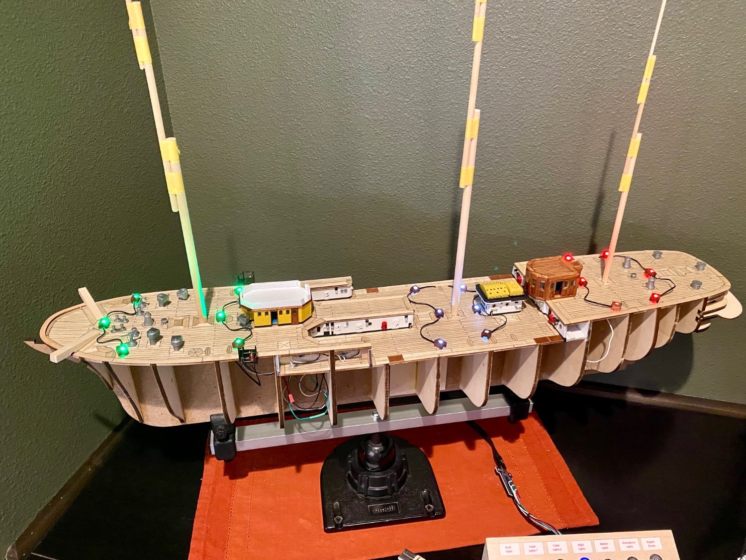
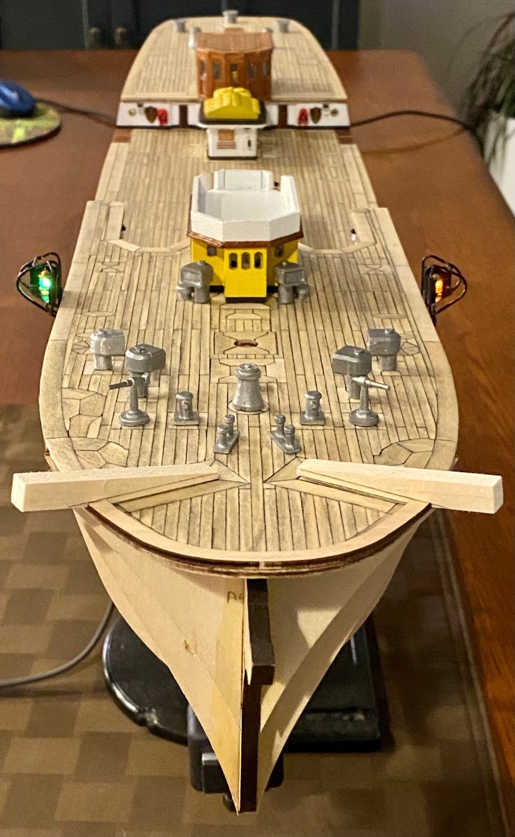
Good evening everyone, thanks for stopping by. In this episode, I have finished or nearly finished the night green-white-red up-lighting the AV is famous for. Hard to see without any of the mast hardware, but I am getting light up to the top of each mast.


- VitusBering, Mike Dowling, clearway and 4 others
-
6
-
1
-
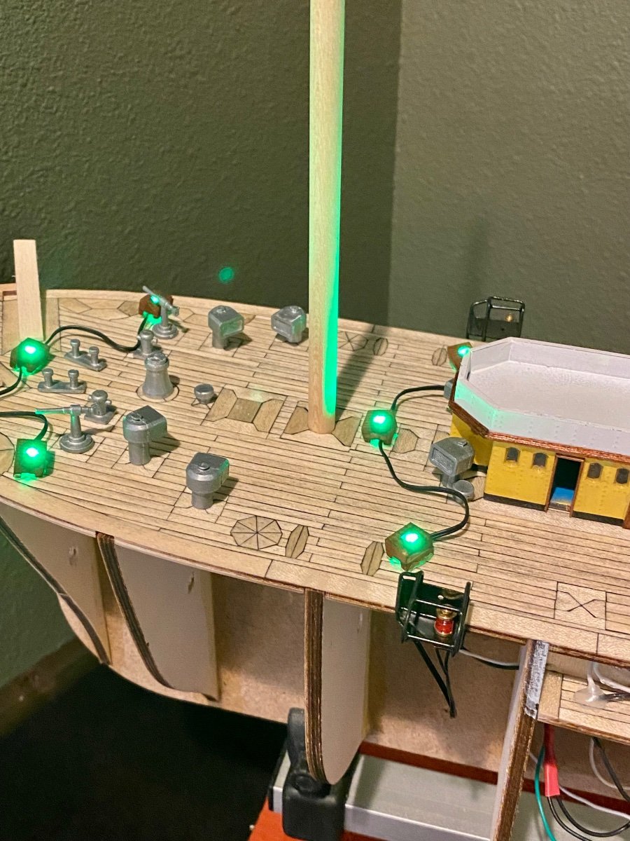
Good evening mates, still working on the lighting…started the night display lighting the AV is famous for. It took a couple of irritations, but this is what I’m going with for the moment. Below is the foremast green lighting.
- Dave_E, Knocklouder, clearway and 2 others
-
5
-
1 hour ago, Mike Dowling said:
Thank you for reply about he doors. I did mean those at deck level which are all I can find. Maybe I adjust the position of the steps to fit those which, it seems from some of the photos would be the way to go.
I found that the OcCre plans are off a bit for where the stairs meet the deck. In my deck plan I moved the opening for the stairs about 15-20mm to hopefully make it all work in the end. Also I added the micro grid to the deck at the location of embarkation / disembarkation.
- Dave_E and Mike Dowling
-
2
-
1 hour ago, Mike Dowling said:
Meanwhile a suggestion/word of warning. I did exactly what I was trying to avoid and when drilling the porthole holes and managed to cut some of the internal wiring because I hadn't remembered correctly where it was. I would suggest that you take some good pictures of your wiring before you do the planking to avoid doing the same thing.
Mike, in my last ship, the HMS Terror, I had a similar mishap. I routed the wires just under the deck, then later I drilled through the deck for some piece of equipment and severed a line. Had to remove a plank and perform micro soldering to fix. I don’t want a repeat of that so I have routed all my wires away from the deck and any walls. Good lesson for us all.
- Mike Dowling and Dave_E
-
2
-
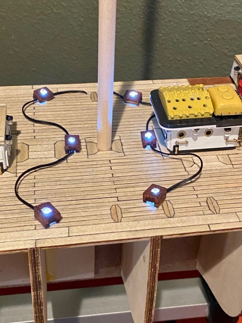
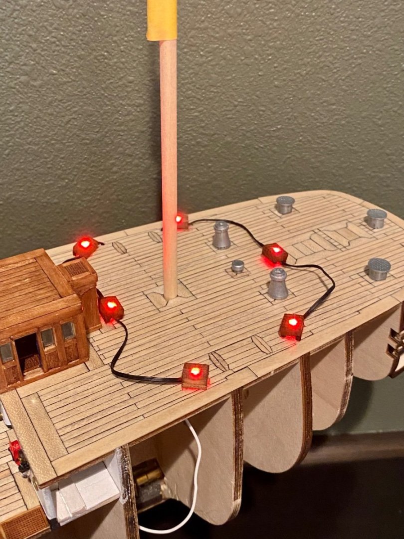
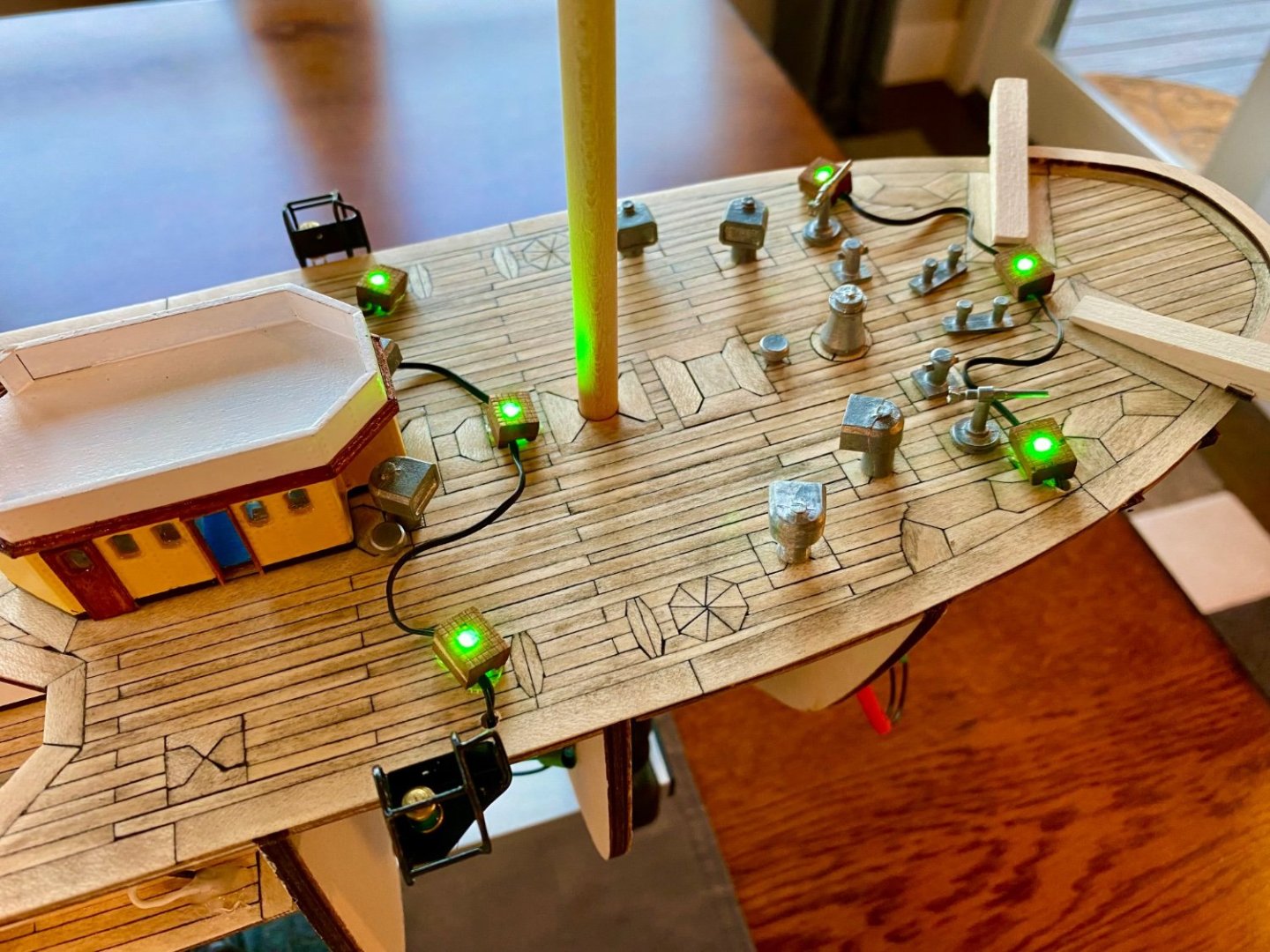
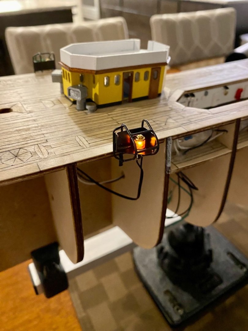
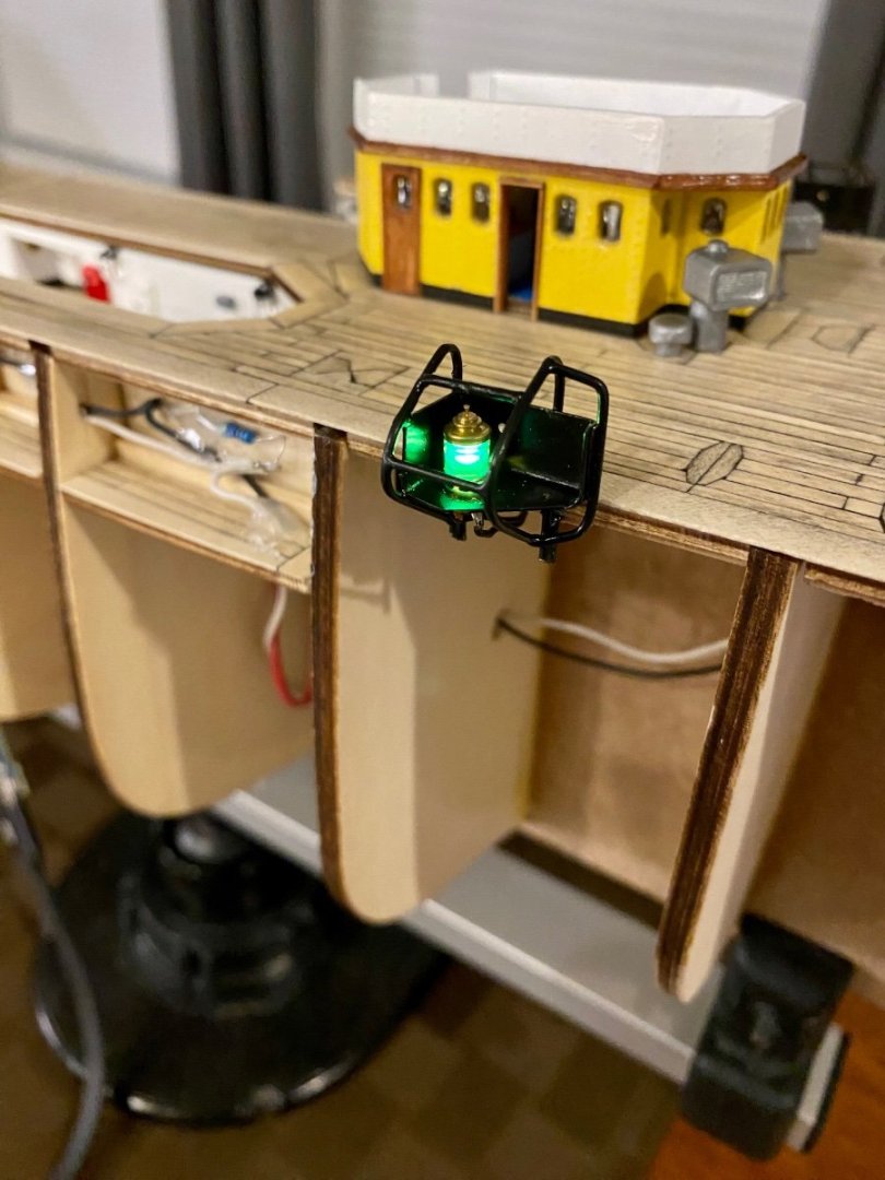
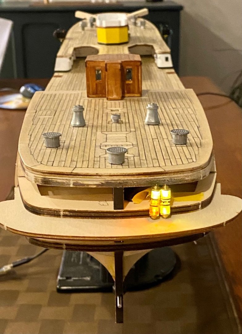
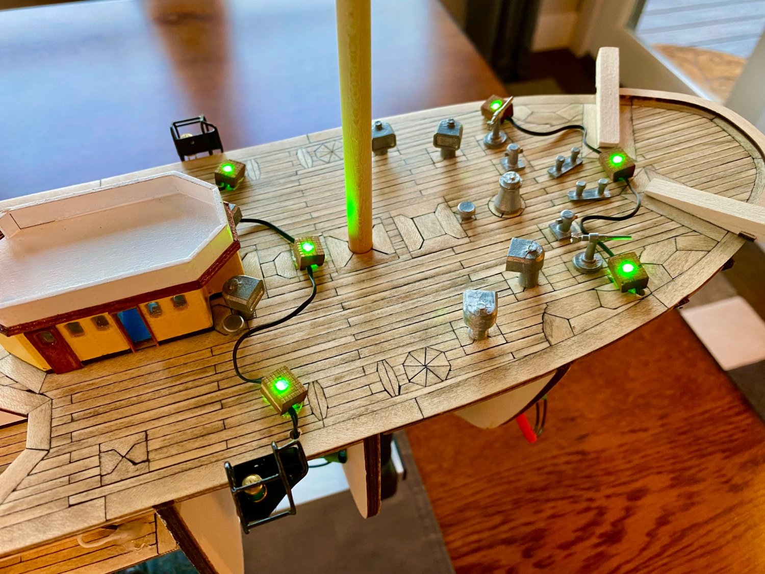
Good evening everyone, this weekends update. I have the marker lights all wired up and working. The only thing missing from this circuit is the lantern on the mizzen mast. Not sure how to build a lantern or purchase one for the correct period style and in the right scale…More work to do on this front.


- Dave_E, VitusBering, ccoyle and 2 others
-
5
-
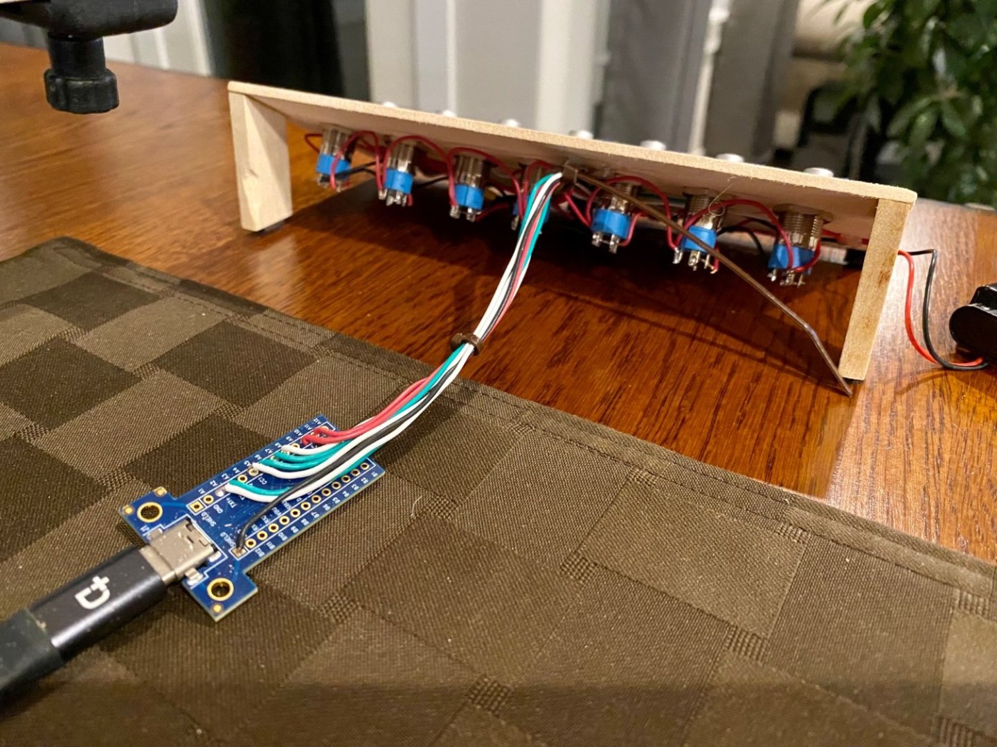
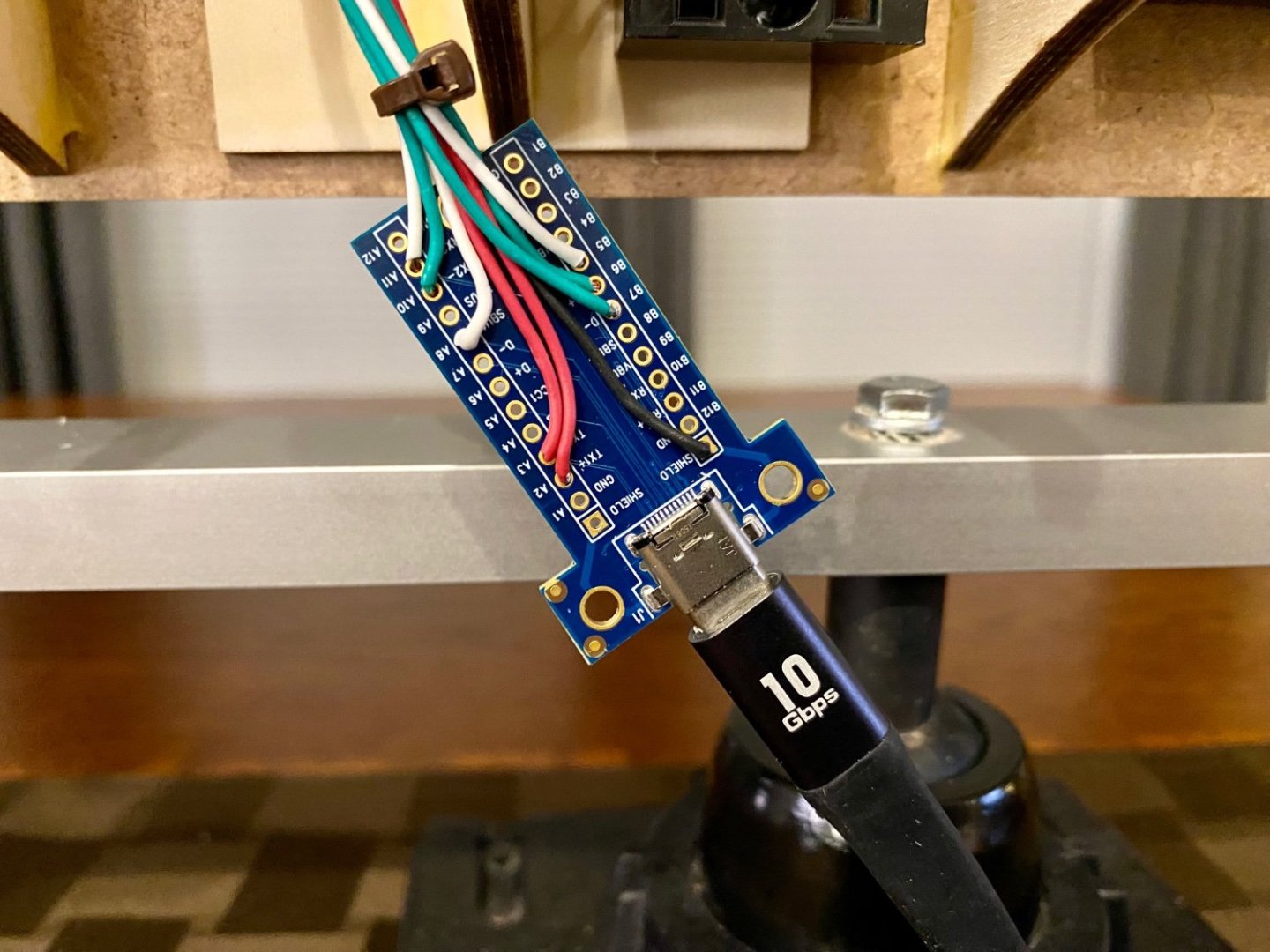
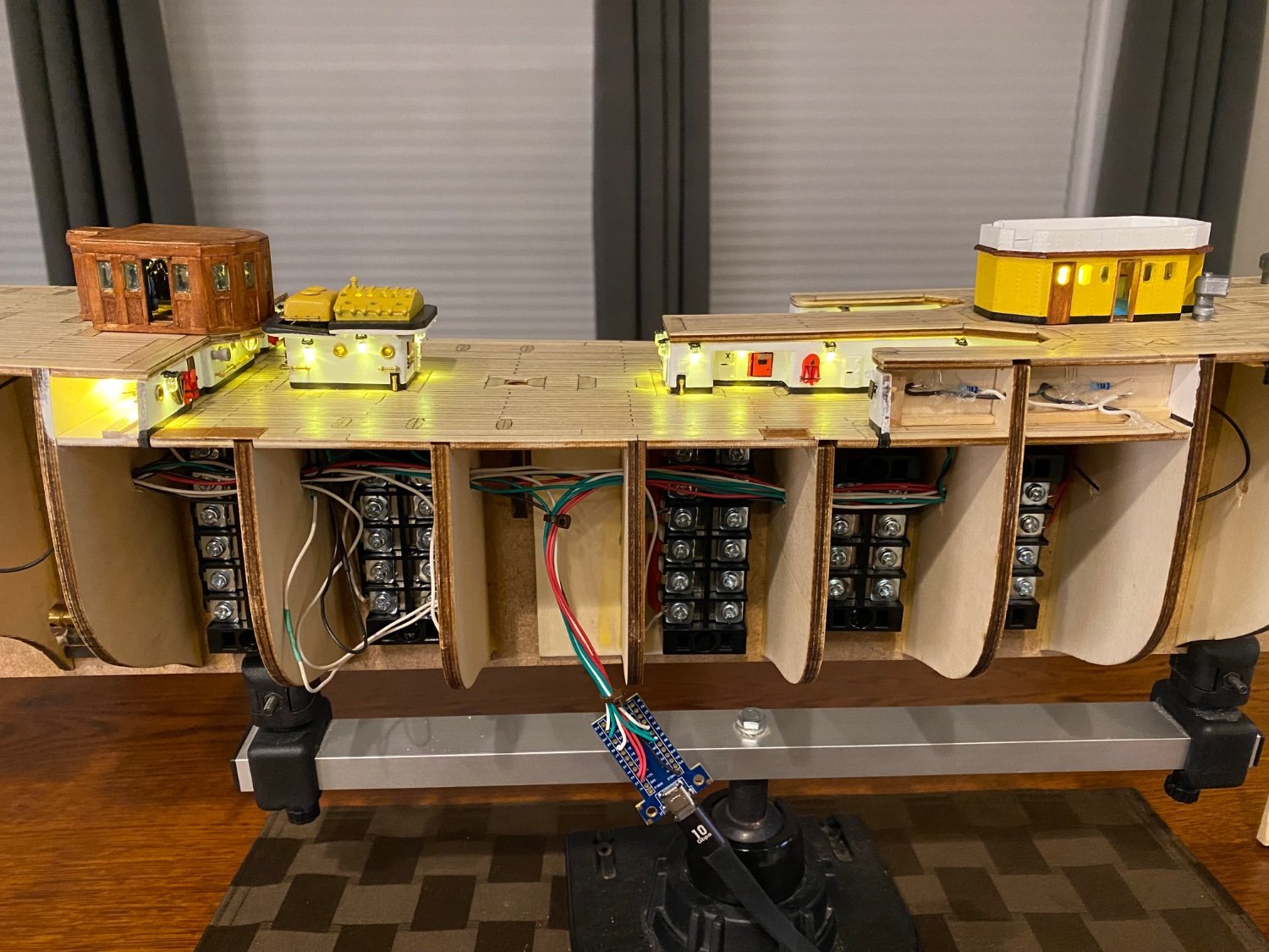
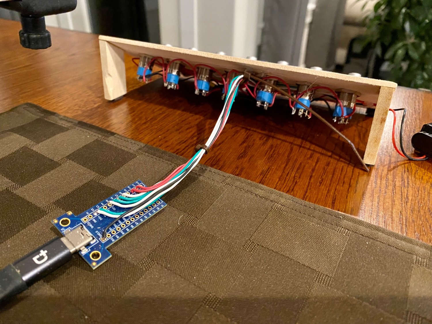
Good evening mates, I finally took the plunge and organized the wires that make this ship work. I used some terminal blocks I had on hand to make the distribution bus, I know, a bit over kill but it’s the engineer in me. I purchased two usb-c terminal blocks, one for the ship that I will install along the keel which will be mostly hidden. The other usb-c terminal will be in the base. When this idea was first suggested, I was excited to finally have a clean solution to get the the power onboard. What I didn’t expect is that a standard high speed usb-c cable is not “straight through”, well, actually I expected the transmit and receive wires to be crossed, but the rest was unexpected. Not only is the cable wired differently if one swaps the ends, but also different when one flips one or both ends, making 6 different wiring combinations. Basically, I wired for only one of the six potential options, which means my cable will only work one way, if I swap the ends or flip one or both of the ends, it will not work. I will be marking which end of my cable goes to the ship and base respectively. With that done, my power cable is all working. Now to finish the lighting.

- hof00, VitusBering, clearway and 1 other
-
4
-
4 hours ago, Mike Dowling said:
What do you think about the side doors Daniel?
Mike, I’m not sure what doors you are referring to. I’ve not seen any images or other information that suggests any other access to the ship other than the two sets of stairs on both sides that can be adjusted to accommodate the sea wall they dock against which then allows access from the sea wall to the deck. Once on board, there are many water tight hatches to stairs leading to lower decks, several water tight doors into the fire control room, and ornate doors leading to officers quarters and conference rooms that can have a waterproof hatch placed over them in the case of heavy seas. On the other hand, I have seen images where some (or possibly all) of the portholes open, but this would not be for human access. I’ll keep my eyes open other hatches along the hull.
- Dave_E and Mike Dowling
-
2


Amerigo Vespucci by DanielD - OcCre - 1:100
in - Kit build logs for subjects built from 1901 - Present Day
Posted · Edited by DanielD
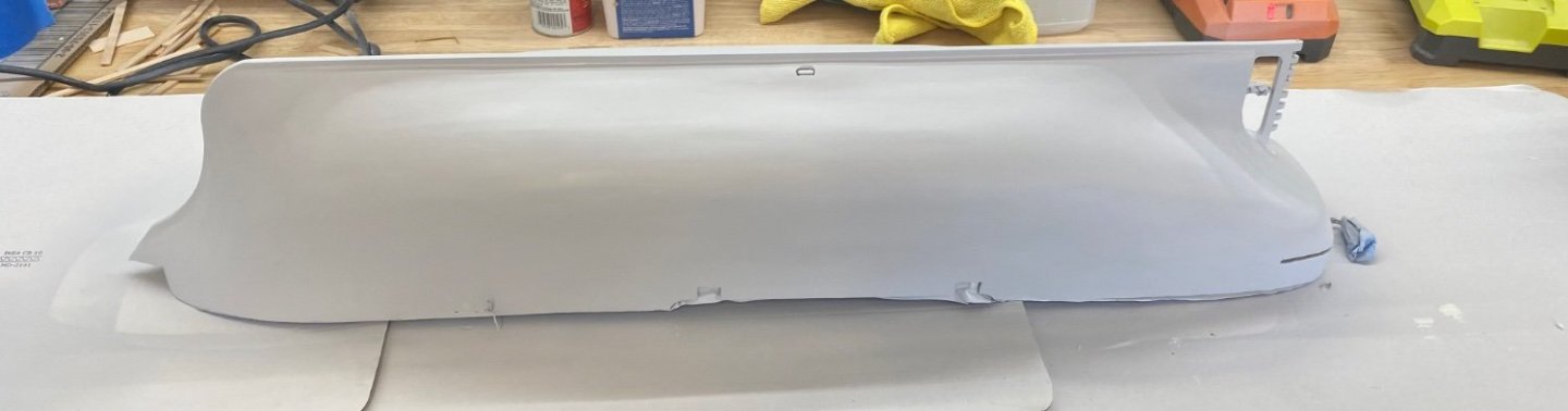
And…another project I’ve been thinking about and working on, the rain gutters which my wife calls the eyebrows 😊. I have the look I’m striving for, now to make a jig so I can produce exactly the same part, 174 times.