DONATION DRIVE - SUPPORT MSW - DO YOUR PART TO KEEP THIS GREAT FORUM GOING!
×


Ras Ambrioso
-
Posts
662 -
Joined
-
Last visited
Content Type
Profiles
Forums
Gallery
Events
Everything posted by Ras Ambrioso
-
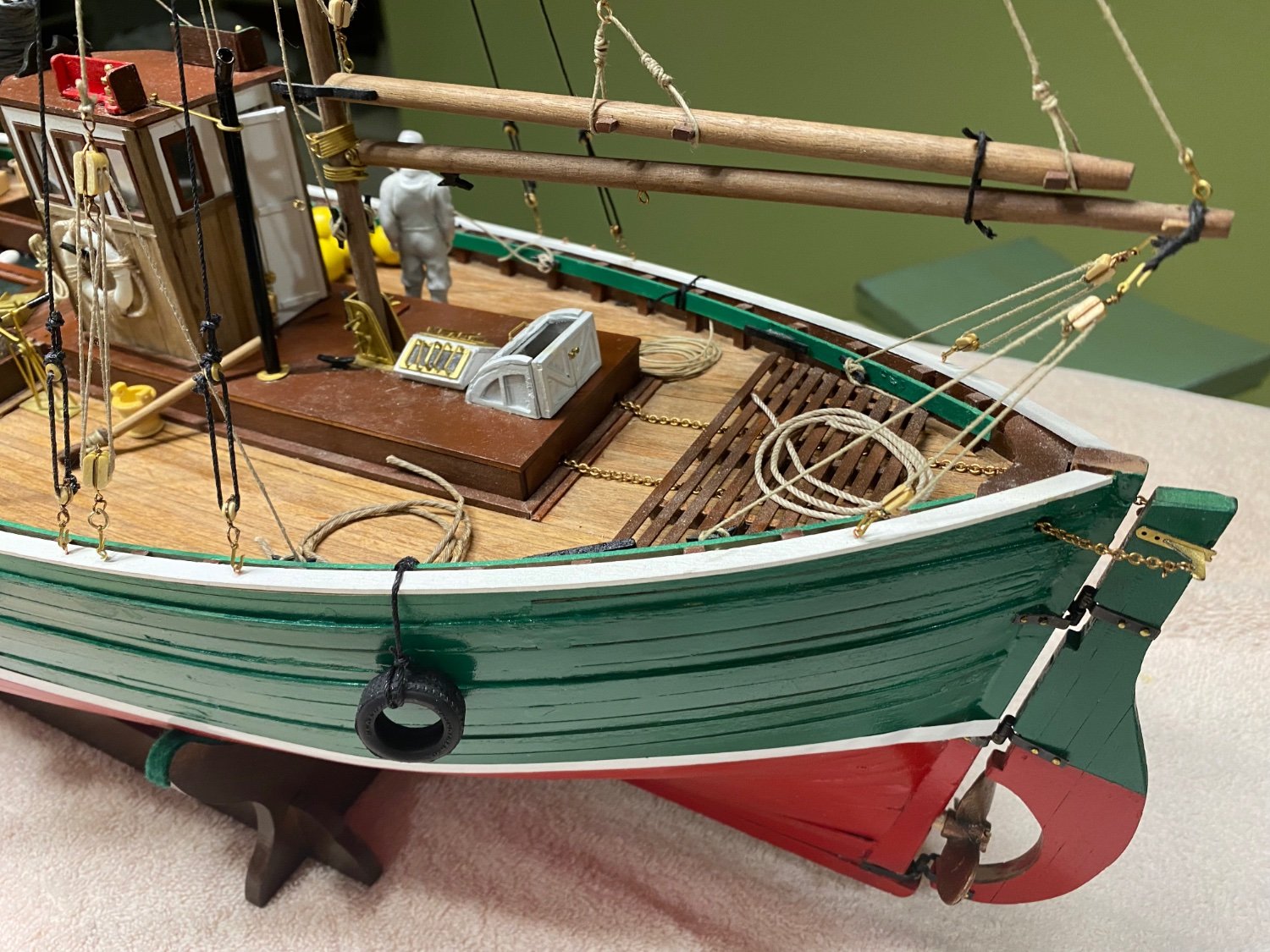
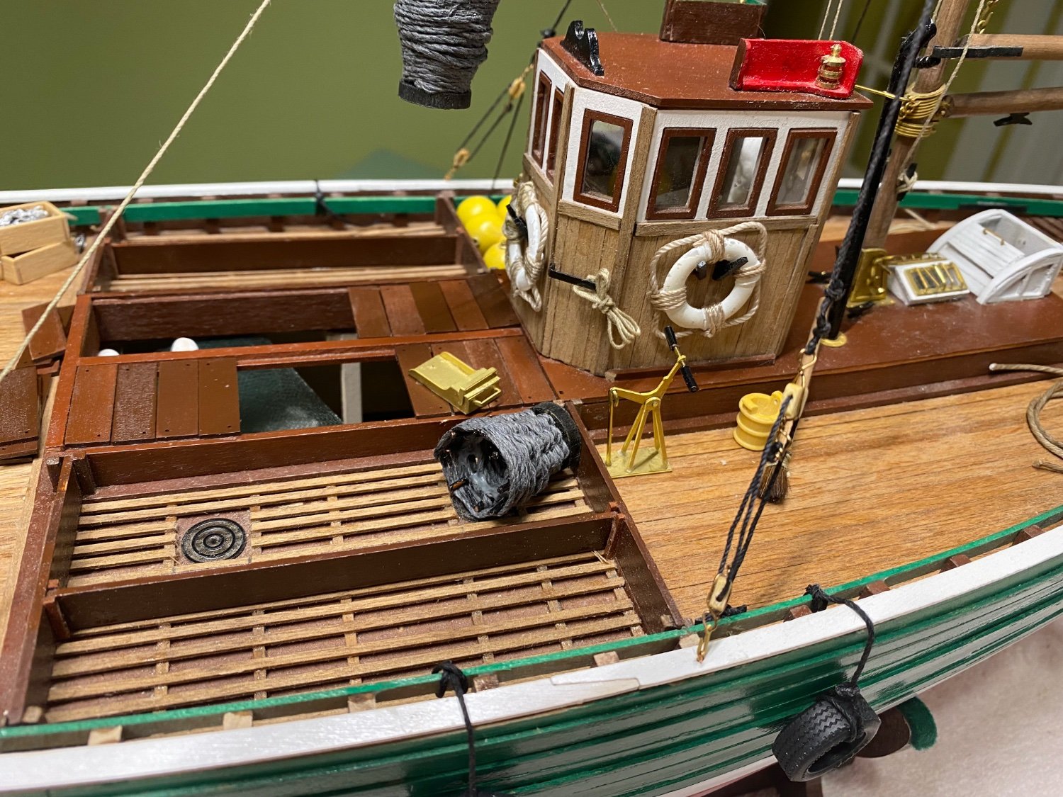
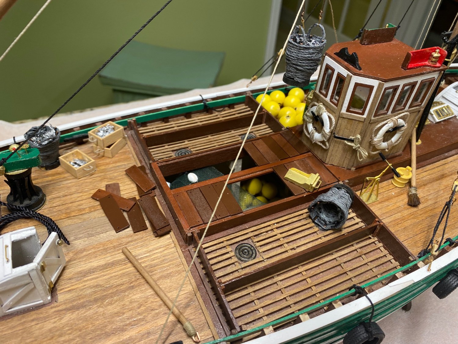
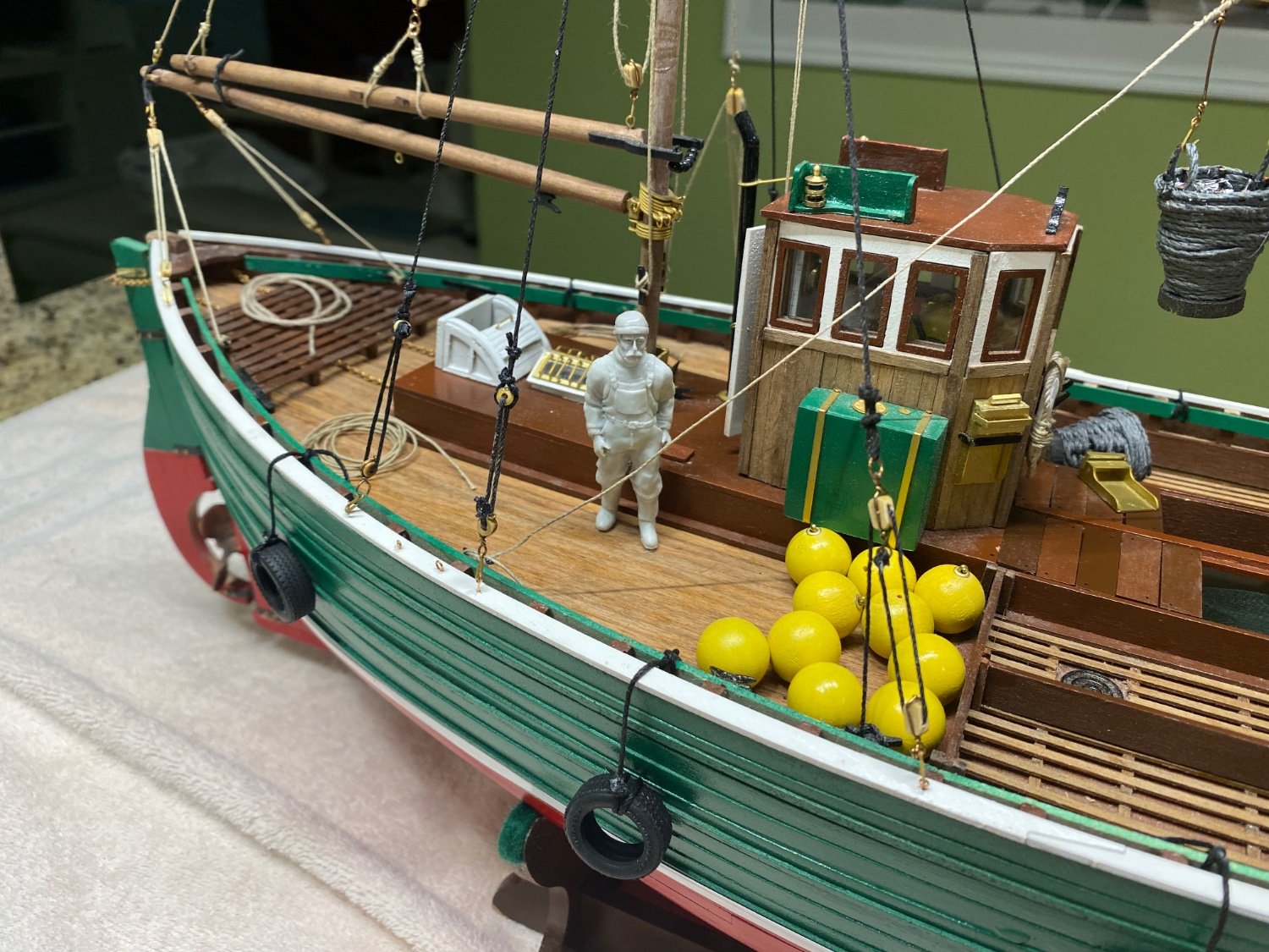
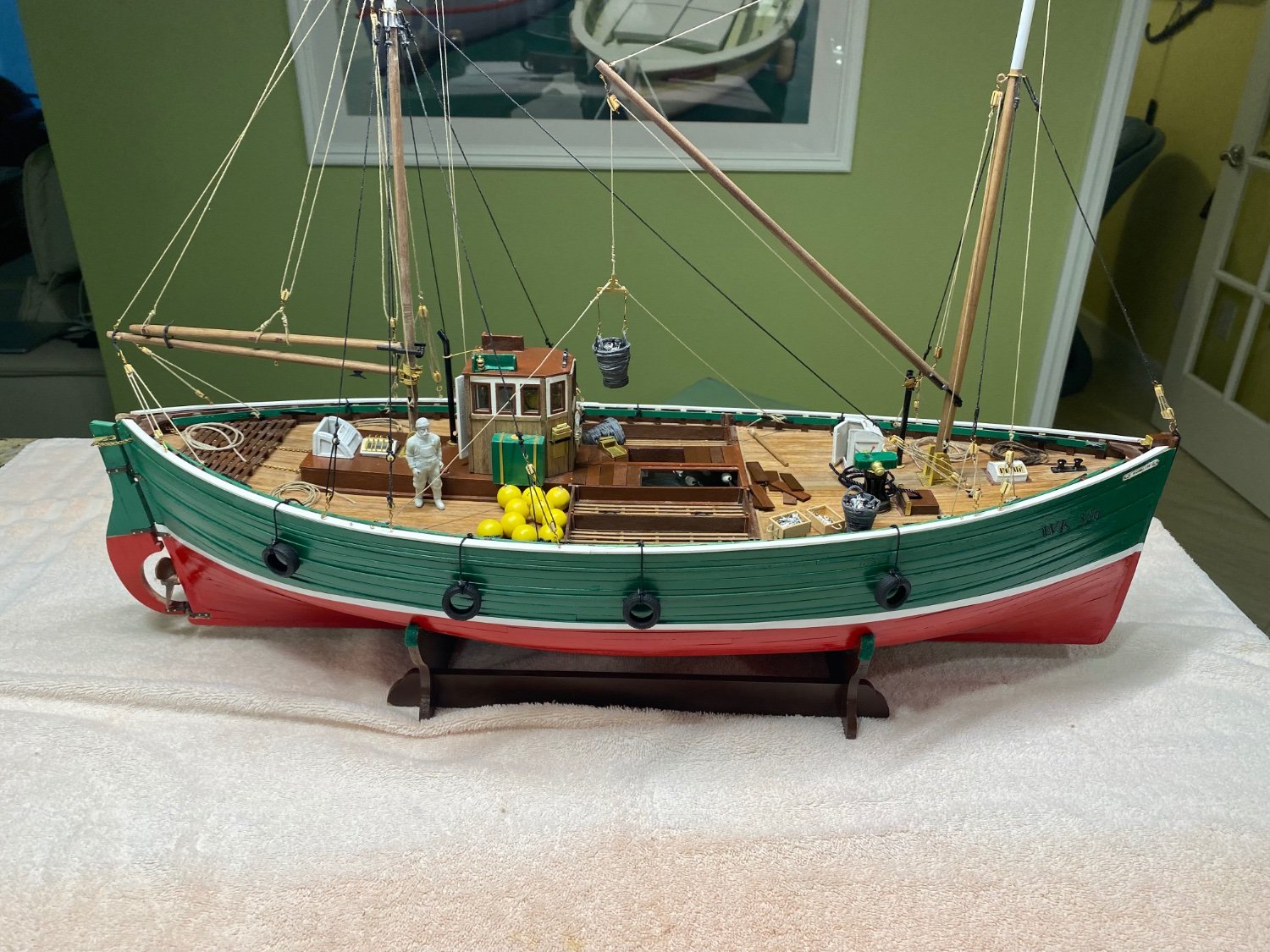
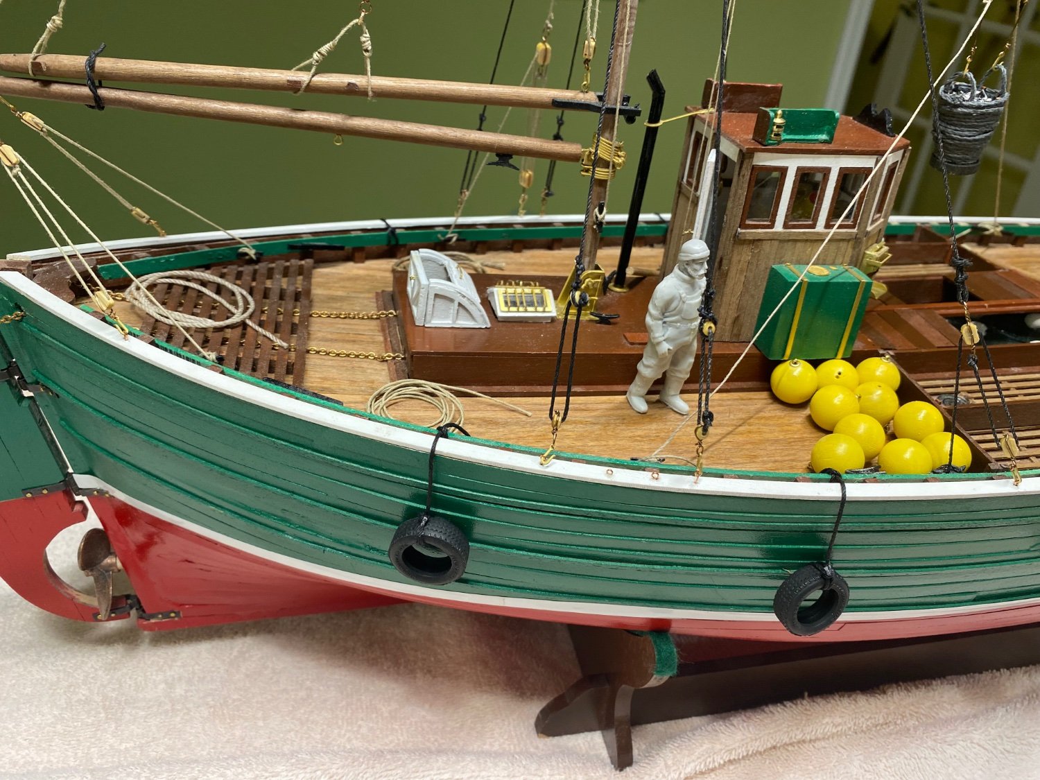
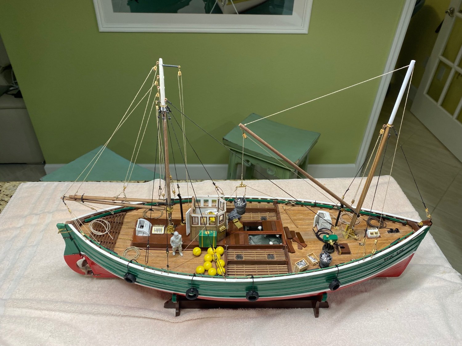
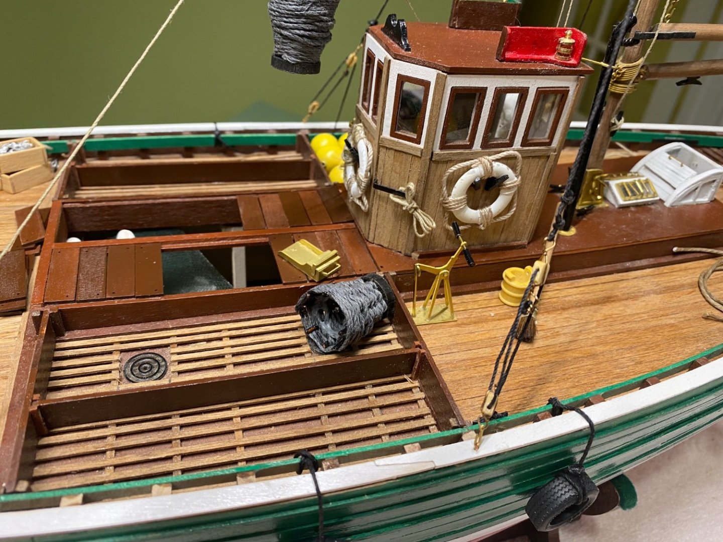
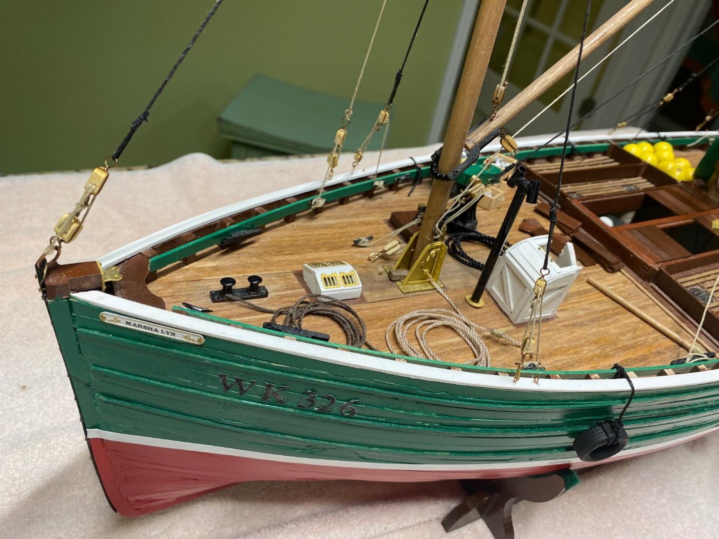
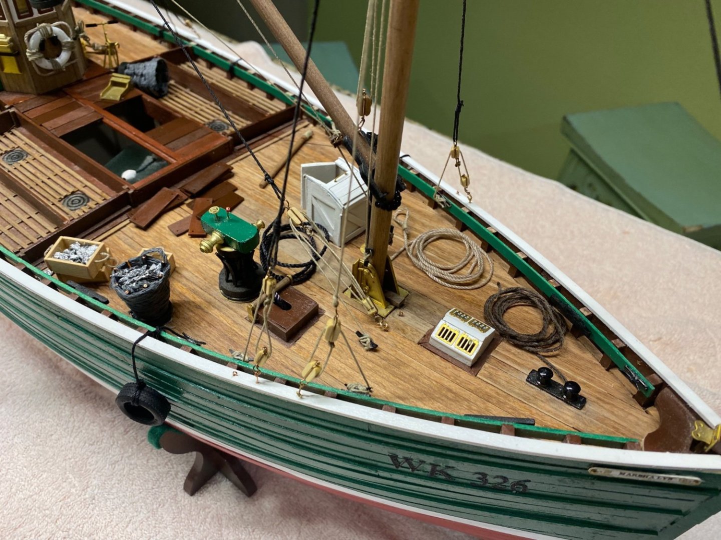
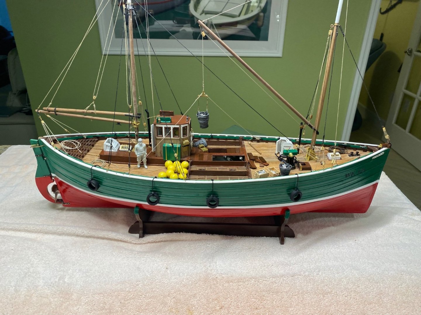
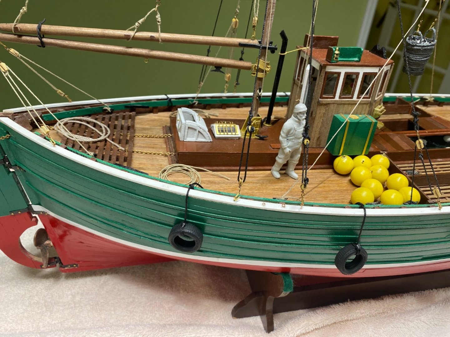
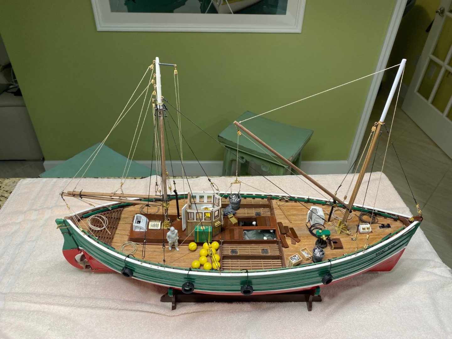
 The Fifie is completed. I would like to post this build in the finished models gallery. I have created an album but I have not been able to upload the photos. Could some one help here. I am following with the pictures of the finished model There are some details still missing which may be completed at a later date. Basically I did not include the small boat and the three drew member are yet to be painted IMG_8659.MOV
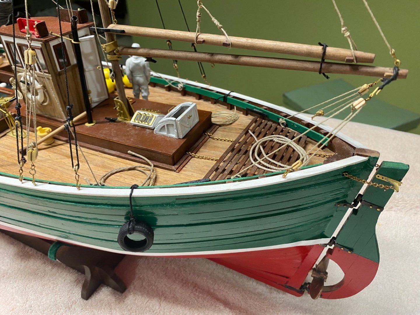


- 112 replies
-
- 11
-

-

-
Wefalck, you bring back memories. I was building all kind of structures in 1940 Cuba using my Erector set. I also remember those Marklin toys. And you are right, the newer generations doesn't appreciate these kind of toys. They are too used to get things already made.
-
I will be taking some time off from this build in the coming weeks, as I need to finish my Fifie. I moved her from the shop to my apartment and, in the move, some of the rigging got loose and a few details need to be completed. I have my previous model, the Emma Berry, in an art exhibit in the lobby of my apartment building. I have been advised that new art pieces are to placed by February 22 and I want to exhibit the Fifie in its place. There are several modelers and painters in our campus and everyone is anxious to see the new pieces. Go visit my Fifie build. Your advise and comments are really appreciated
-
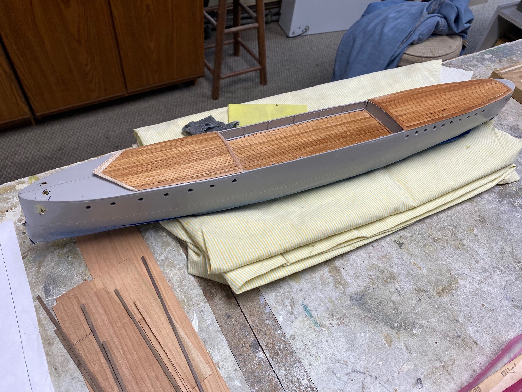
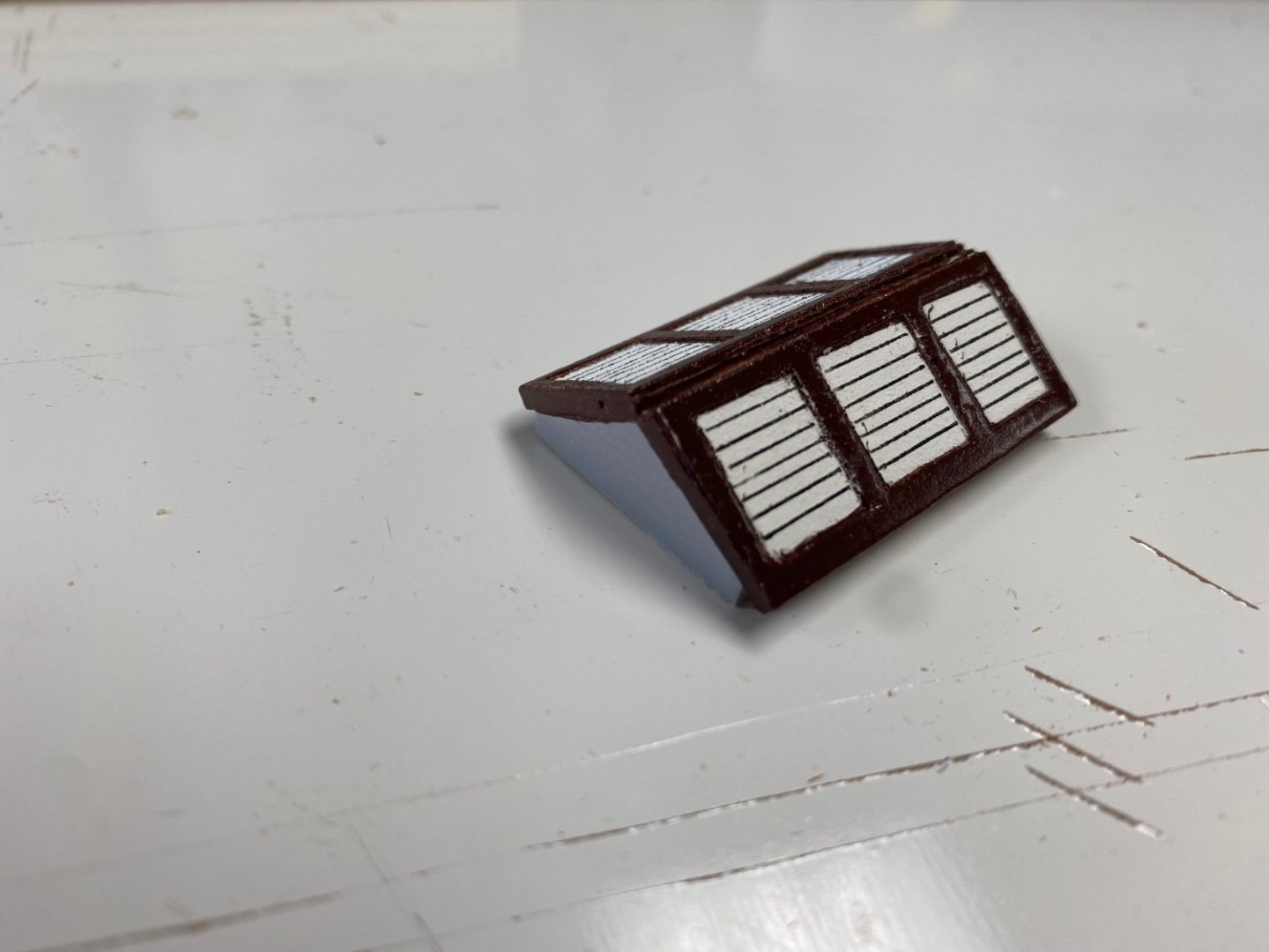
More progress. This is my final version of the big skylight. I used card stock paper to make the frames and actually painted the louvers. Finished the galley and engine room access adding a couple of glazed portholes. I also added a black paper to simulate the roofing material. This is how the middle deck is looking. Working on the chart room and bridge. Again, using my learning from watching y'alls ( pardon my slang) builds, I decided to make the sides of the chart room with card stock and wood strips. So far so good: The above picture shows the different sections of the walls. Once finished they will glazed with acrylic paper, cut out from the base and installed in the wood frame already fabricated. I have to apologize with some of the roughness of my cuts but I am having a ball with this build. I am still waiting for my propellers from Australia and I have been advised that they have reached the US, and are currently going through customs. I have been extremely pleased with the service from Modelers Central in Australia. When I placed the order online I didn't realize they were from "downunder" and have been waiting several weeks for the shipment. However, Modelers Central have religiously keeping me informed of the progress of the shipment via e-mails. My kudos to them. As I see the end of this build near I am already searching for a new project. My selection is a 40 foot fast motor launch (ML) made by Thornycraft early in the 20th century. It was named Mimi and with its sister, Toutou, were moved on land from the Cape to lake Tanganyika to fight the germans in those waters during WW I. The story was the basis for the movie The African Queen. The model will be in 1/24 or 1/32 scale and I plan to build a working miniature of the Hotchkiss QF gun.
-
Great work Steven. Keep us informed.
-
Roger, I love your explanation for the fresh water tank. However, I still thing that this tank had to do with the potable water service. What you refer to is a condensate tank but the vent will be directed to the stack as it is live, albeit low pressure, steam. This is what I love about this forum. We can offer our opinions and knowledge to be shared by all. You are totally right about keeping the manual pump for emergencies. Thanks again for the comments. There were a reason why I selected this model. This period, was a time of change , new technologies were cancelling previous ideas, but, there was an overlap in their application. A steam powered vessel was also provided with sails, just a in case. The automobiles shared the roads with the horse buggies, etc. ,etc. Just like we face today in our present world.
-
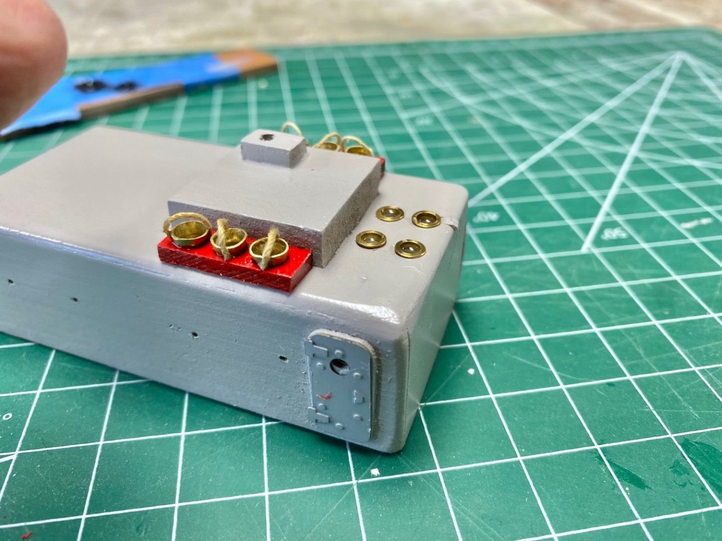
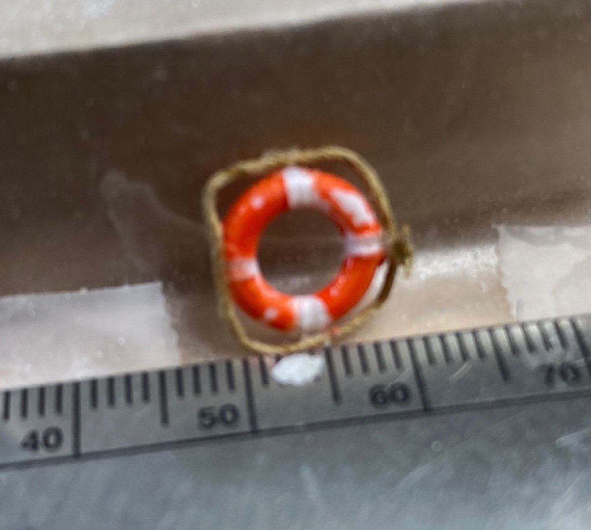
A little more progress on the little things. Following comments on this forum, I redid the lifesaver's rings using my "nail jig" to make the rope loops around the ring and then using very thin strips of masking tape to a secure the rows to the rings. Now this is how the boiler casing is looking now. I am reworking the fire standpipe on the front wall of the casing. Still anxiously waiting for my 1/2" propellers from Australia. Thanks for following
-
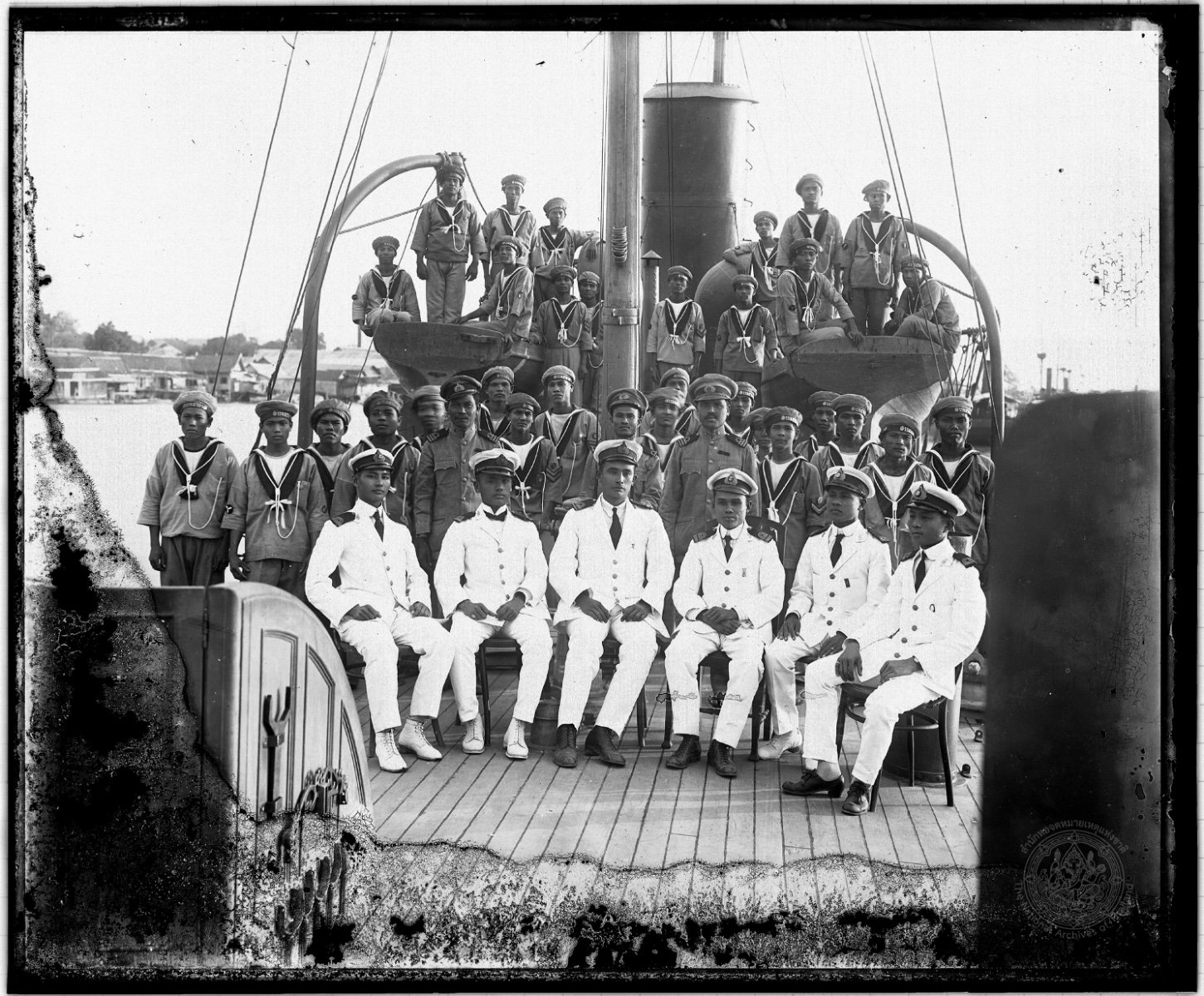
Wefalck, thanks for your comments. I have very little information on the details of this ship. I have been in contact with a friend in Thailand that had some information on the sister vessel of Amapá: Suriya Monthon. However, we really don't about these pumps. The top view on the plans show a FW (fresh water) and SW (sea water) pump located forward off the boiler casing. Looking at the top view, I figured, they may have been hand operated vertical pumps. The deck plans also shows a downton manual pump for the bilges. But, since this is in 1907, I thought that electric power may have come to Thornycraft and thus provided this ship with a steam power generator illuminating the cabins and powering the ship's pumps. I have carried that assumption forward and I am presenting a fire water (sea water) standpipe in lieu of the SW pump and FW (fresh water) refill and supply lines to the fresh water tank from the engine room. The sea water standpipe and hose could also be used for regular sea water flushing of the decks. I will provide these same details on the aft wall of the chart room. The downton bilge pump will remain on deck and as relic of previous technologies. Another interesting item of research is that the Suriya Monthon photo of the mizzen mast only shows the standing rigging. The plans indicate that the ship was furnished with sail rigging also. I came back to my reasoning that, in 1907, using steam for power was sufficient and there was no further need for sails. So this is the way I am going to finish this model. I will also add a wireless antenna between the masts. Radio for sure. Darn, I love this research! Following is the picture from the Suriya Monthon.

-
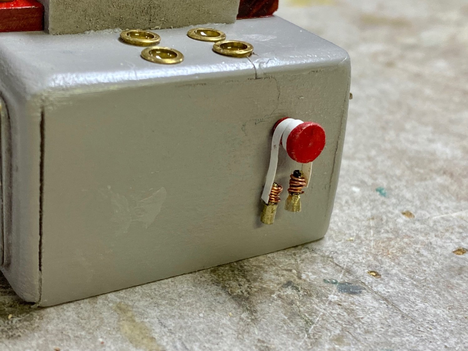
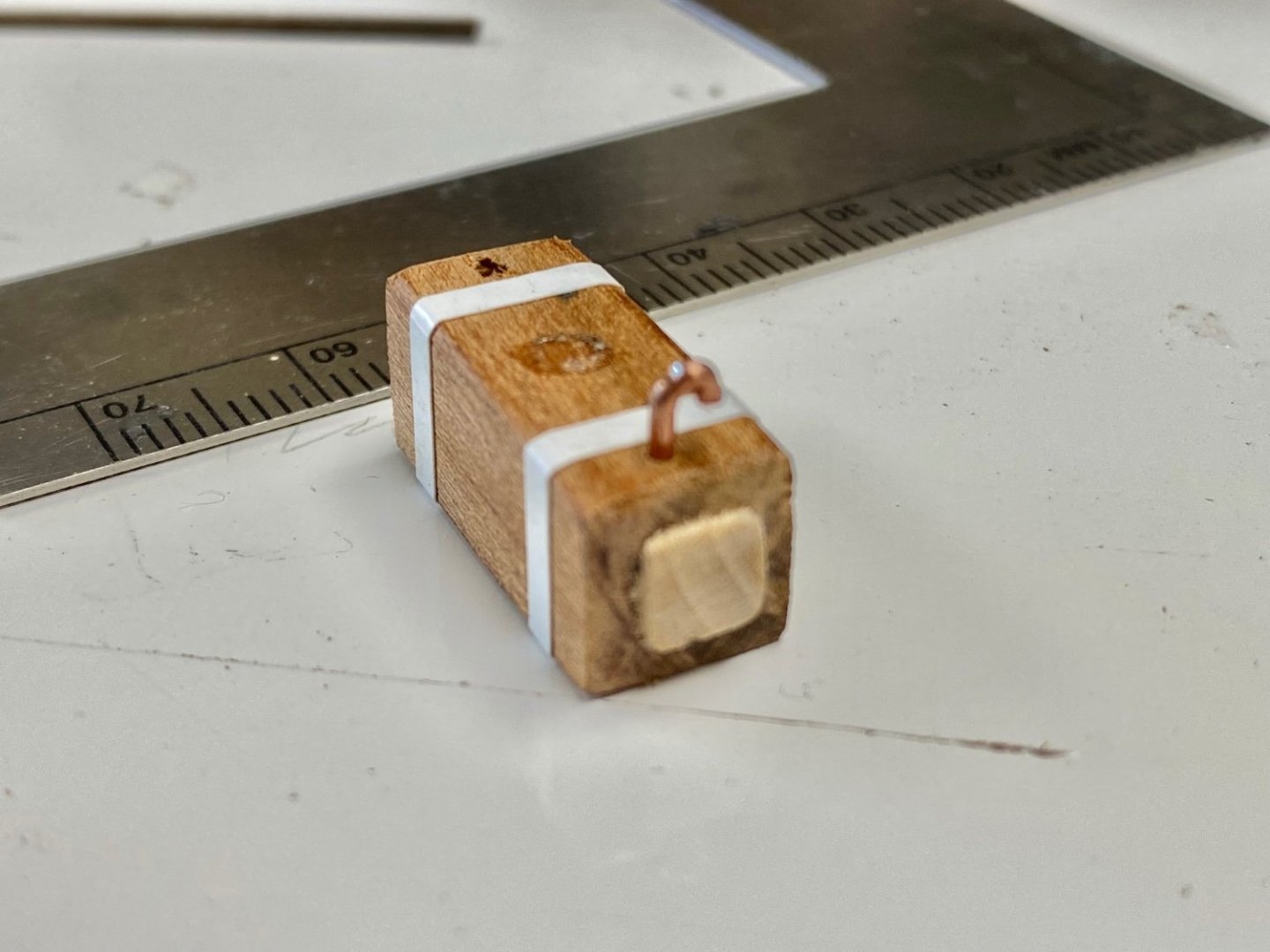
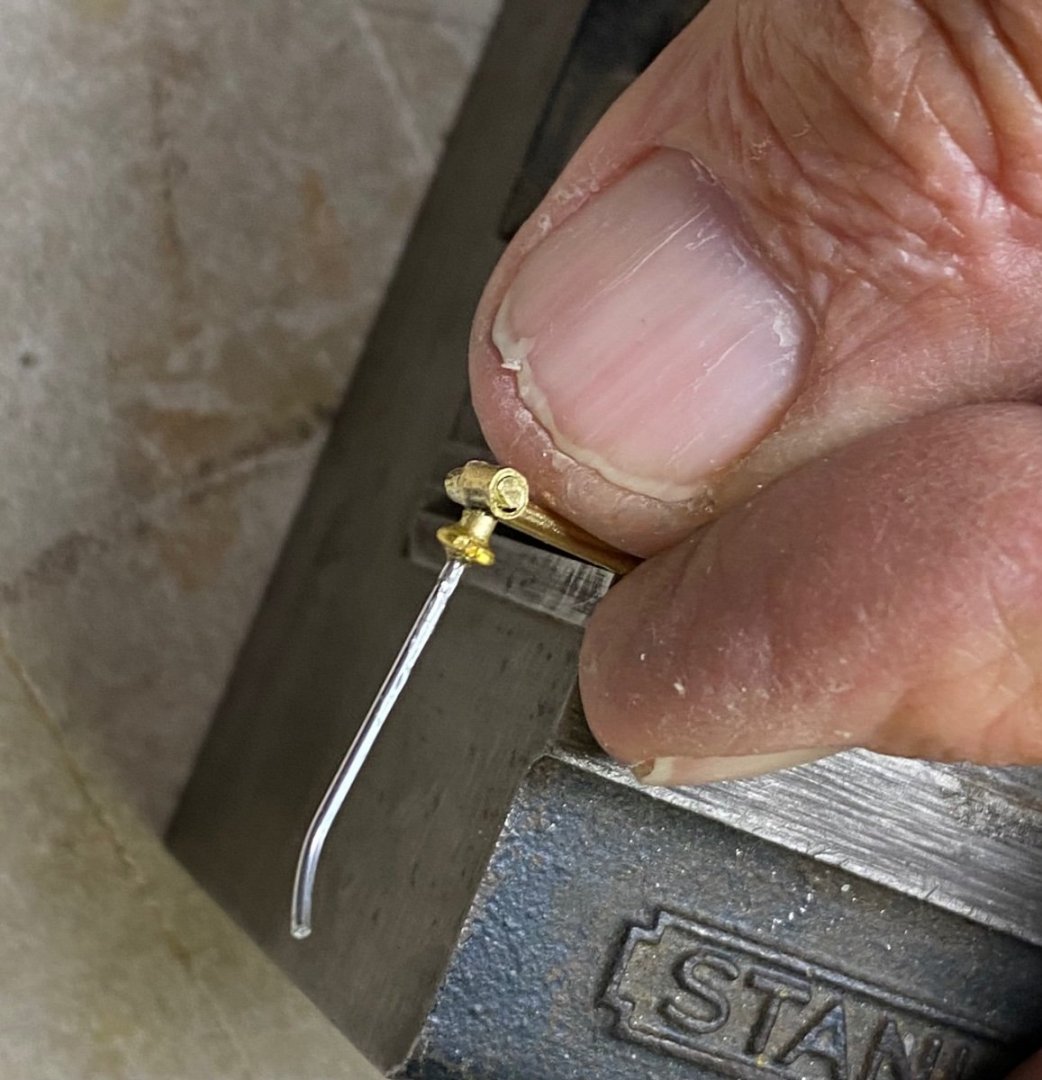
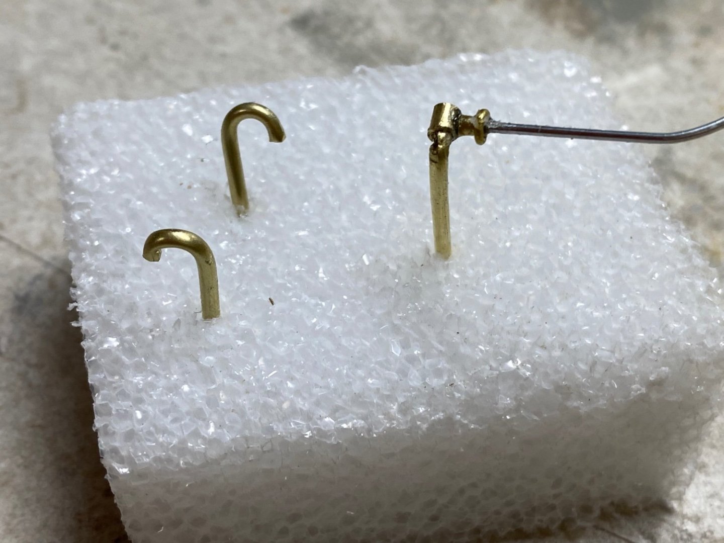
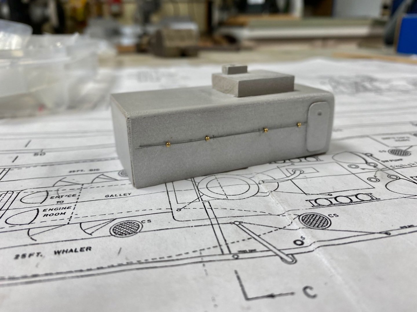
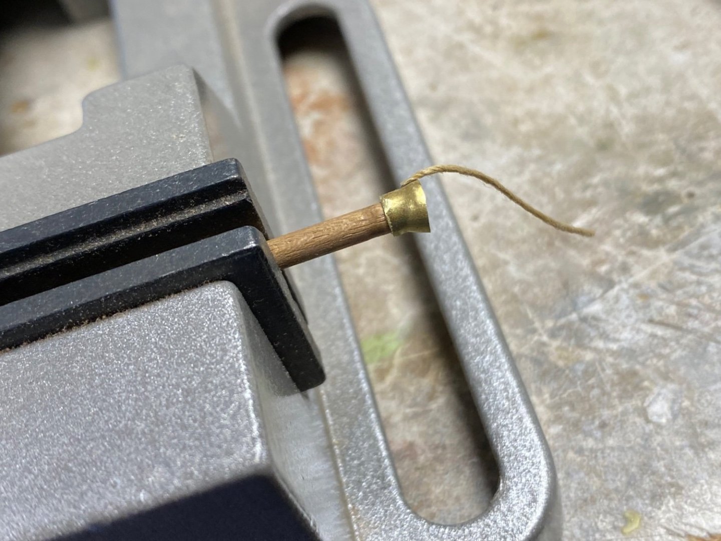
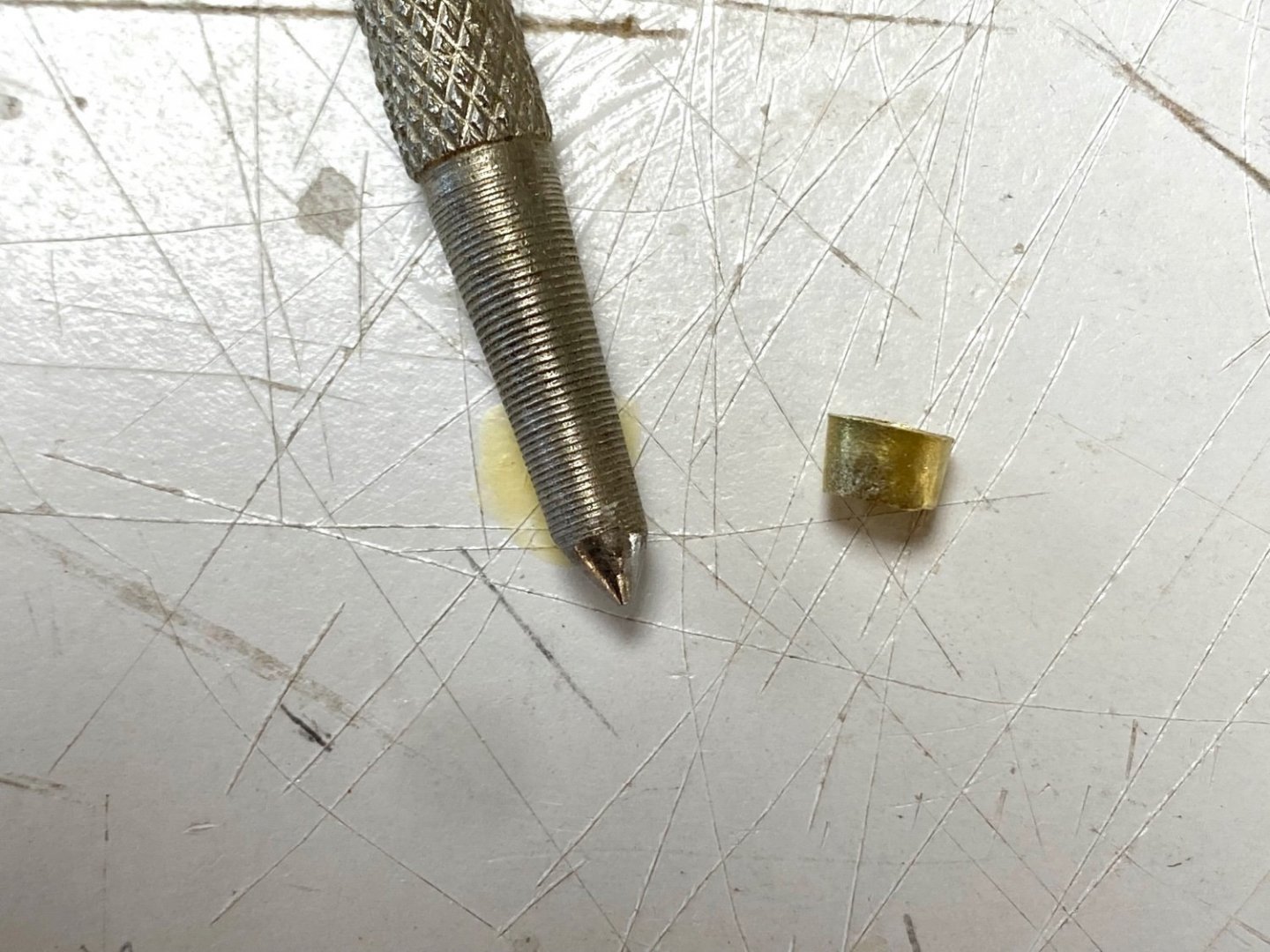
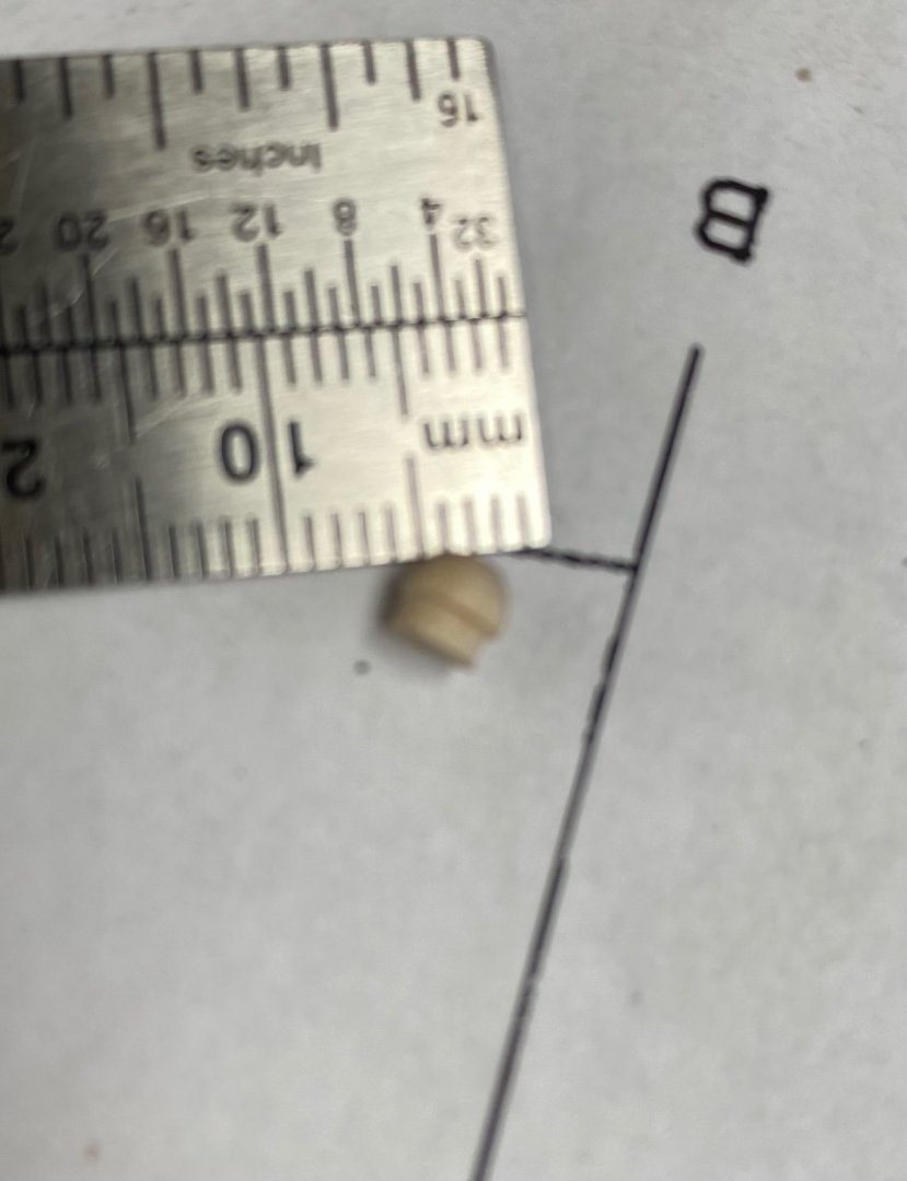
Propellers have not arrived so I continue working on the superstructure details. I deviated from the plans a bit with regards to the water tanks. I could not figure out why would they have a seawater water tank so I decided to make a bigger fresh water tank to sit on top of the boiler casing. This is the tank before painting and installing a feed pipe. Added the sky lights and the fire buckets to the casing. Also notice the detailed WT door (Brass etching). The plans I have for this ship indicated that two pumps were located in the forward wall of the casing. A fresh water and a sea water pumps. I decided to install a fire station in the forward wall of the casing including a standpipe and fire hose. The fire hose gave me a lot of trouble since I couldn't get the materials to wrap around the spool as I wanted. Finally I used a very thin strip of white vinyl tape and fabricated a connector and a nozzle. I also fabricated the smallest thing I have ever made: a gate valve for the standpipe. And following is the standpipe before cutting out the excess wire. The photo also shows some of the deck vents that will be installed in the casing walls. My next little project is the stack. I am considering making the stack out of heavy (lacquered) paper. I am practicing in making the cylinder by wrapping around a proper size dowel. This will be my first use of paper in modeling.

-
Thanks guys y'all are my inspiration
-
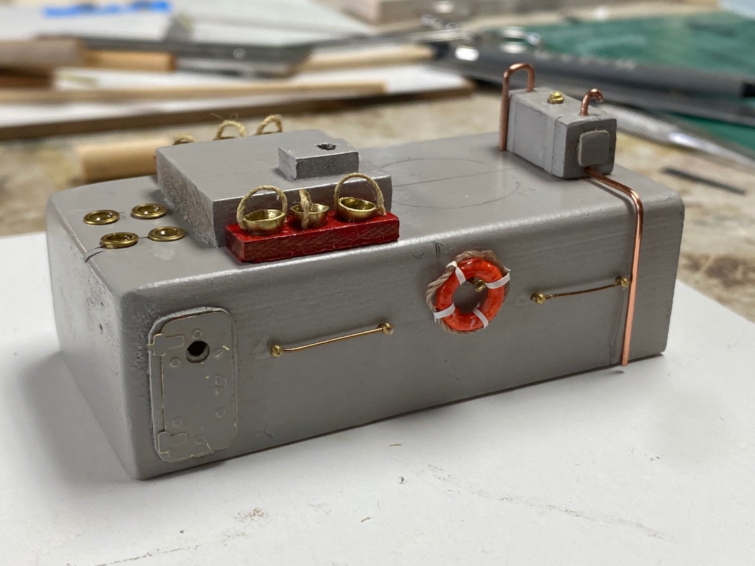
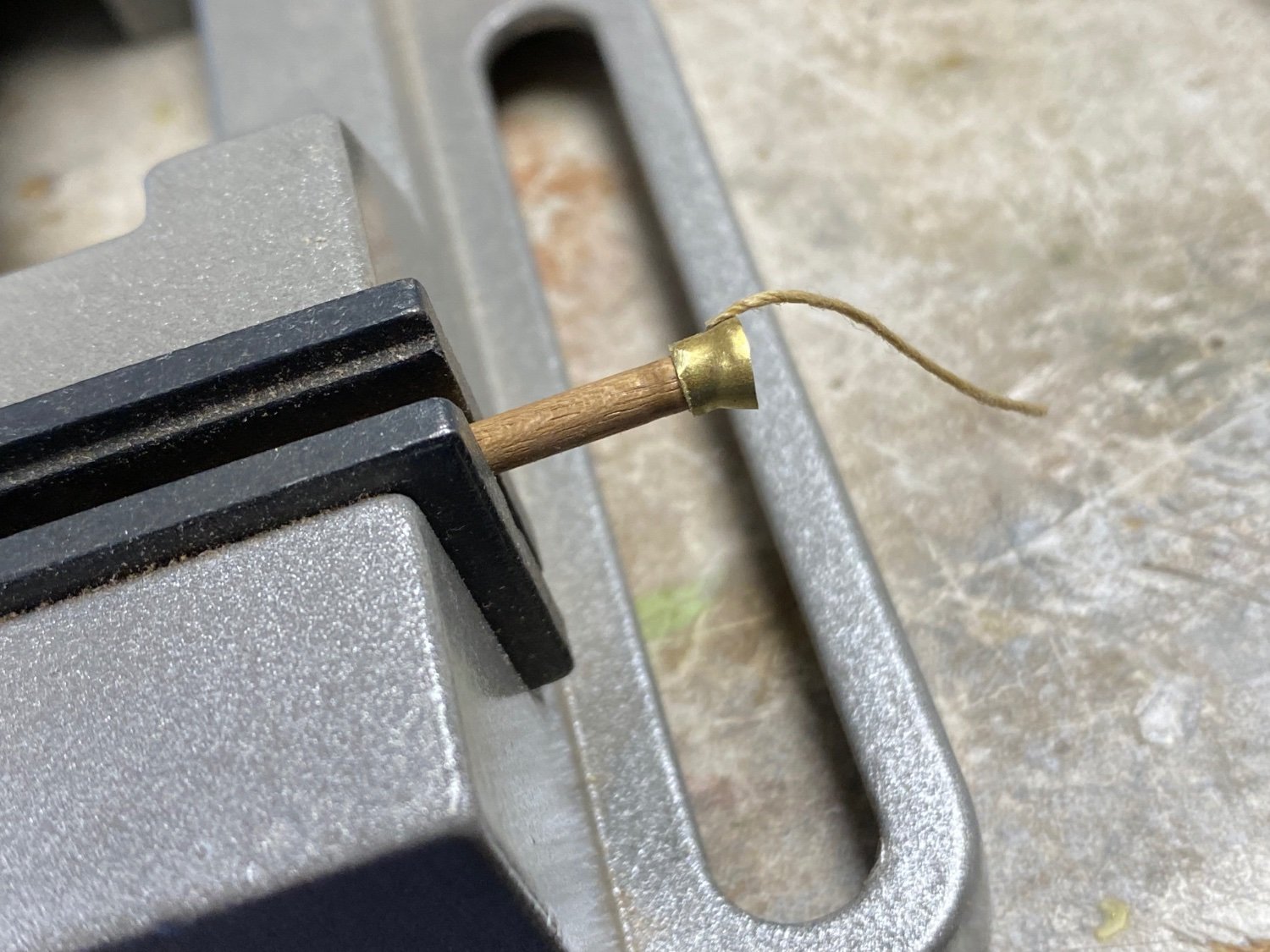
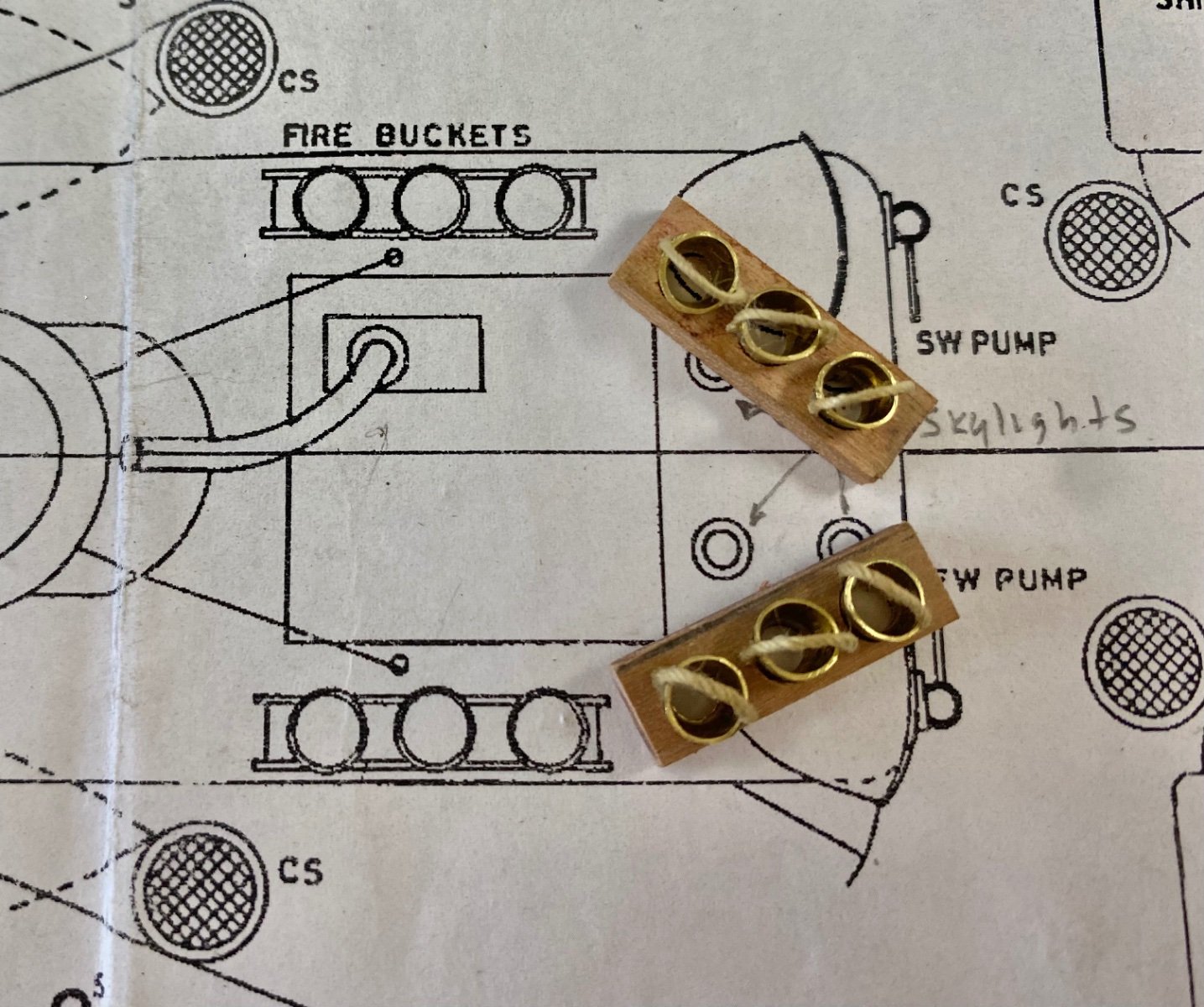
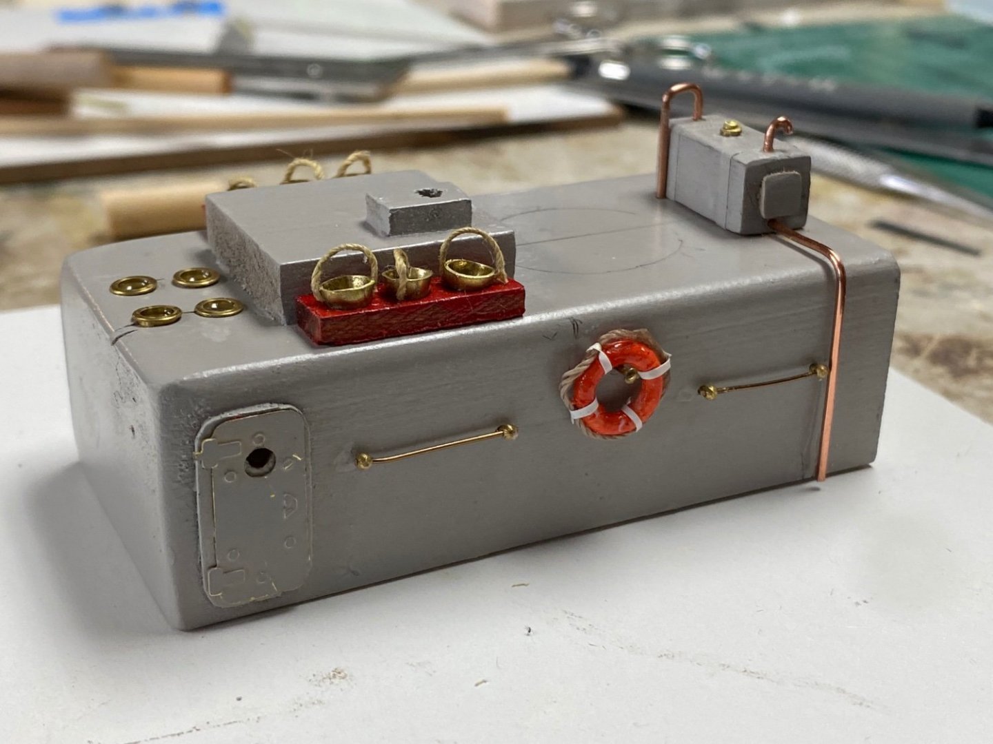
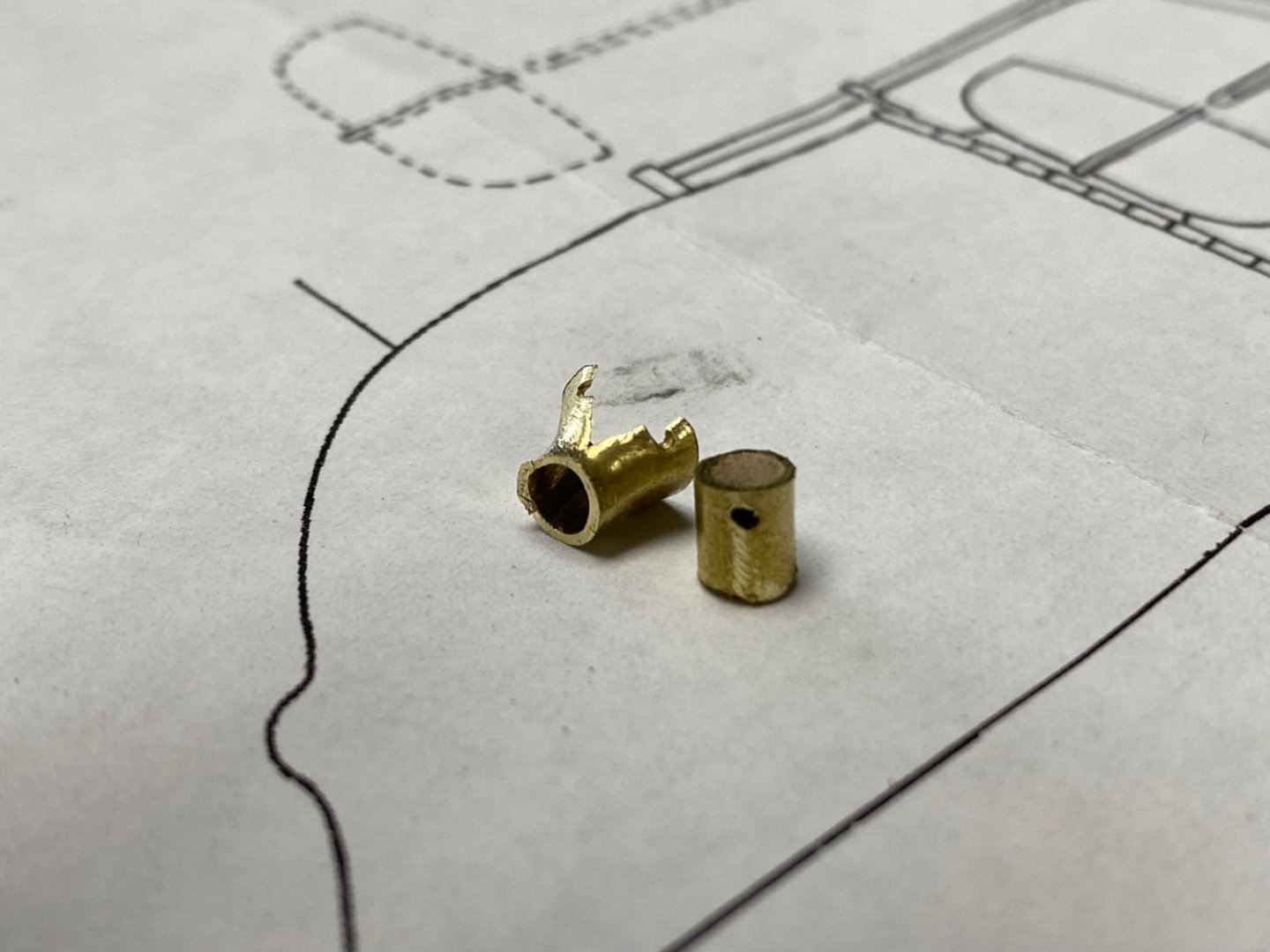
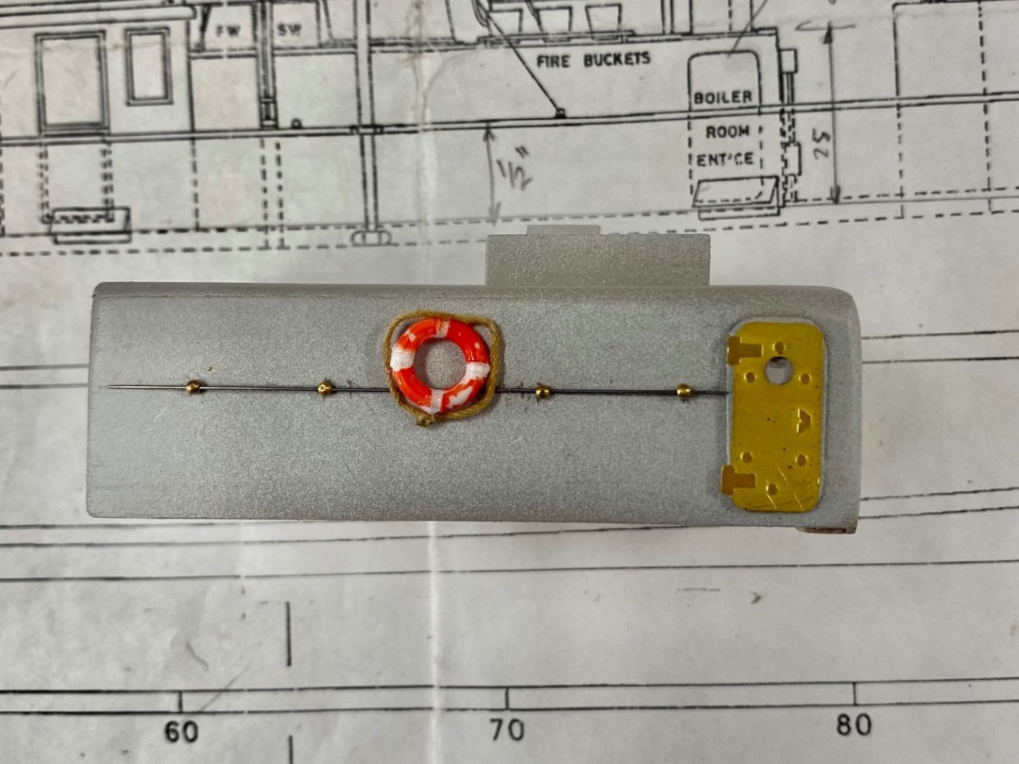
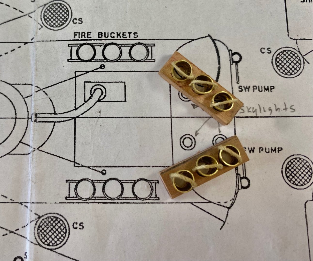
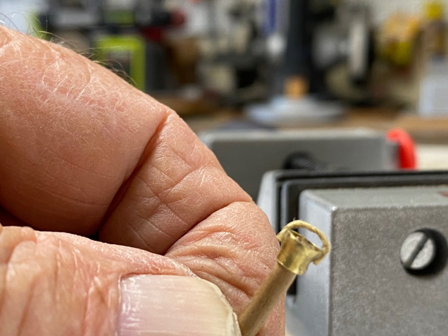
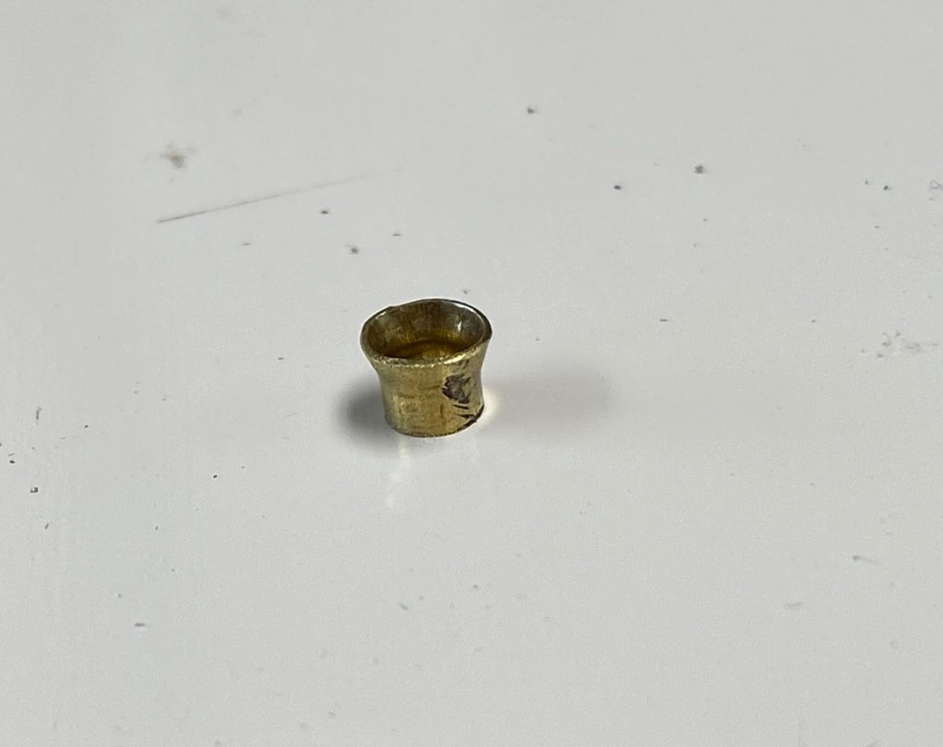
After a rainy, dull weekend I went back to the miniaturization work on Amapá. By the suggestions of this forum, I was going to add rope handles to my little fire buckets. I thought it would have been difficult to drill the tiny holes on the sloping side of the already fabricated buckets. So I decided to fabricate new buckets and pre-drill the holes. Using a wood dowel as a mandrel I proceeded to drill the tubing all the way across . Good! However, I forgot my engineering studies on stress, and when I tried to swage the bucket, the brass gave up. Bad! After spending a couple of hours on this exercise I was back to step one. I then decided to glue the rope handles. Again, using the wood dowel mandrel, I deposited a tiny drop of CA on one side and carefully located the rope's end. After the CA set, I placed glue on the opposite end and completed the loop. And this is the way my fire buckets look on their racks. In the plans the boiler casing is very bare, showing only one watertight door for access. I thought of adding a handrail for the crew to hold on on heavy seas. I used the leftover eyebolts from my previous build, the Fifie. Also completed the life ring using tape instead of serving the hanging rope. I also had purchased some etched WT doors. This is a preview of the final look. I am enjoying my first scratch build, I love the planning and the experimentation on methods for the fabrication of these miniatures. And it makes me even more aware of the talents of some of our micro-engineers like Valeriy and Welfack.


-
Guys thank a lot for your replies and suggestions. First on the life rings I like the idea on using canvas to attach the hanging line. This will be a lot easier to do than the serving and I can use vinyl drafting tape for it. Good tip. Secondly on the fire buckets. I like the idea of using a rope as the handle. At this scale it be a lot easier fir me. Good tip. For the bottoms, since they can’t be seen, I was going to use glue as I did for the portholes and then fill them with sand. I have to do a little more research if to use sand or leave them empty. Thanks again for all your comments and extraordinary source of research.
-
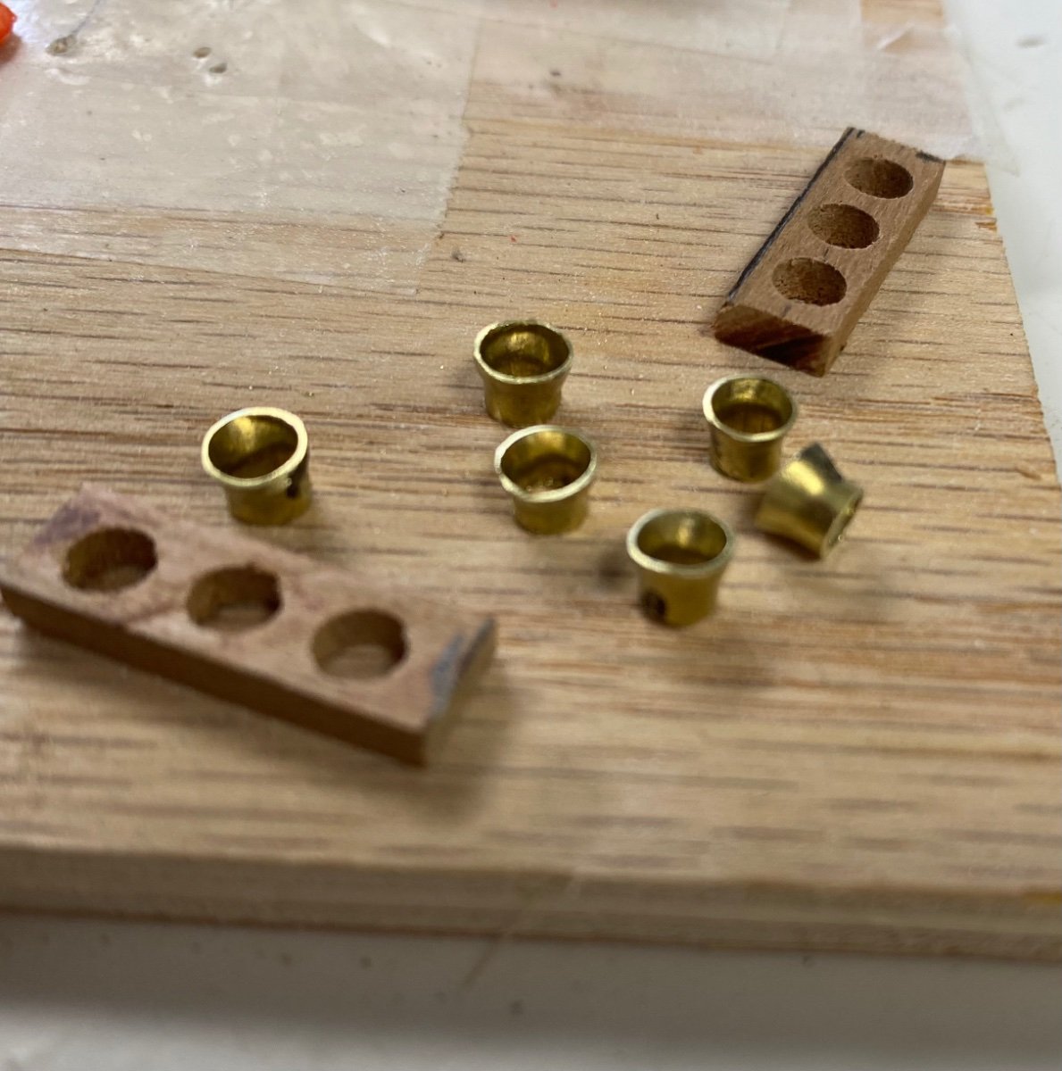
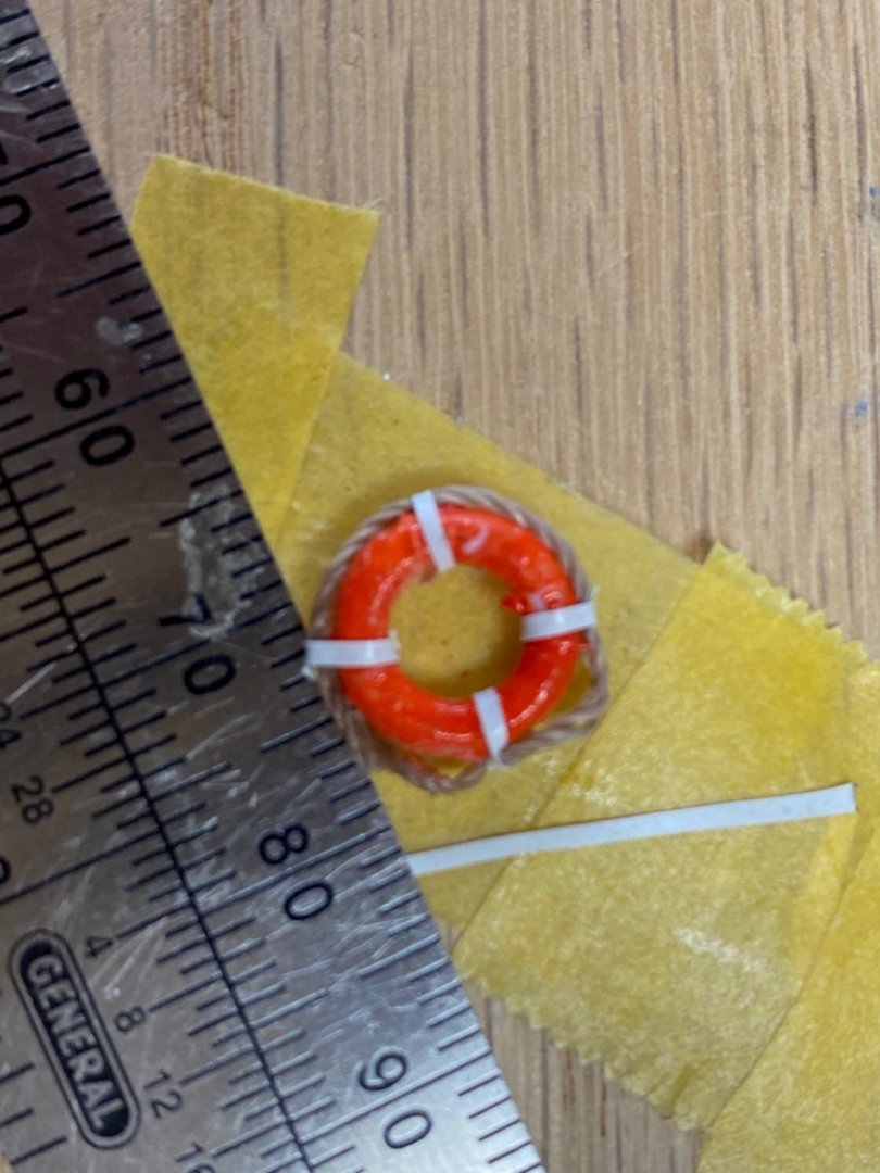
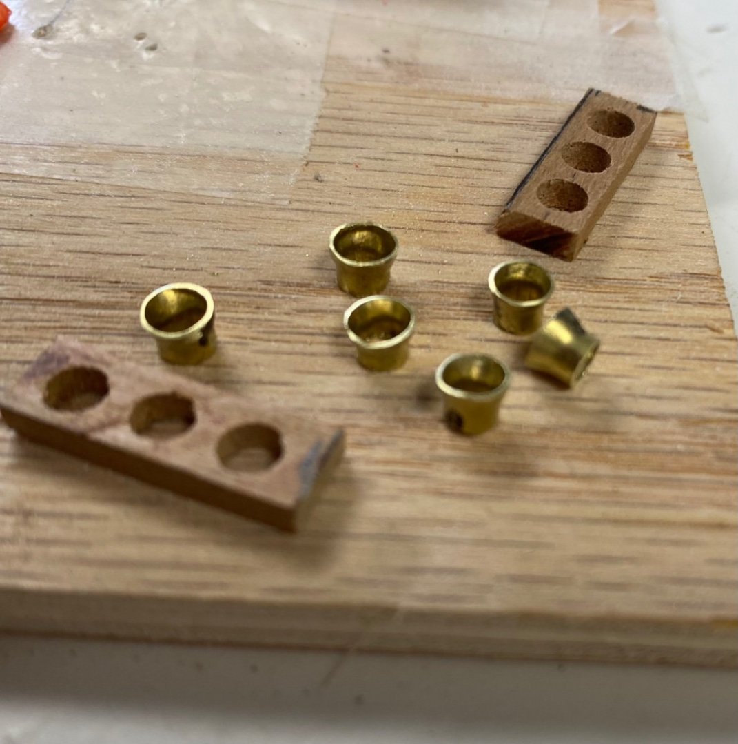
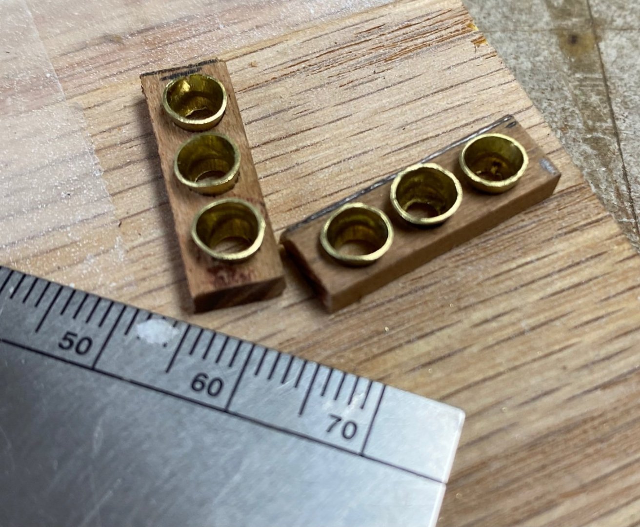
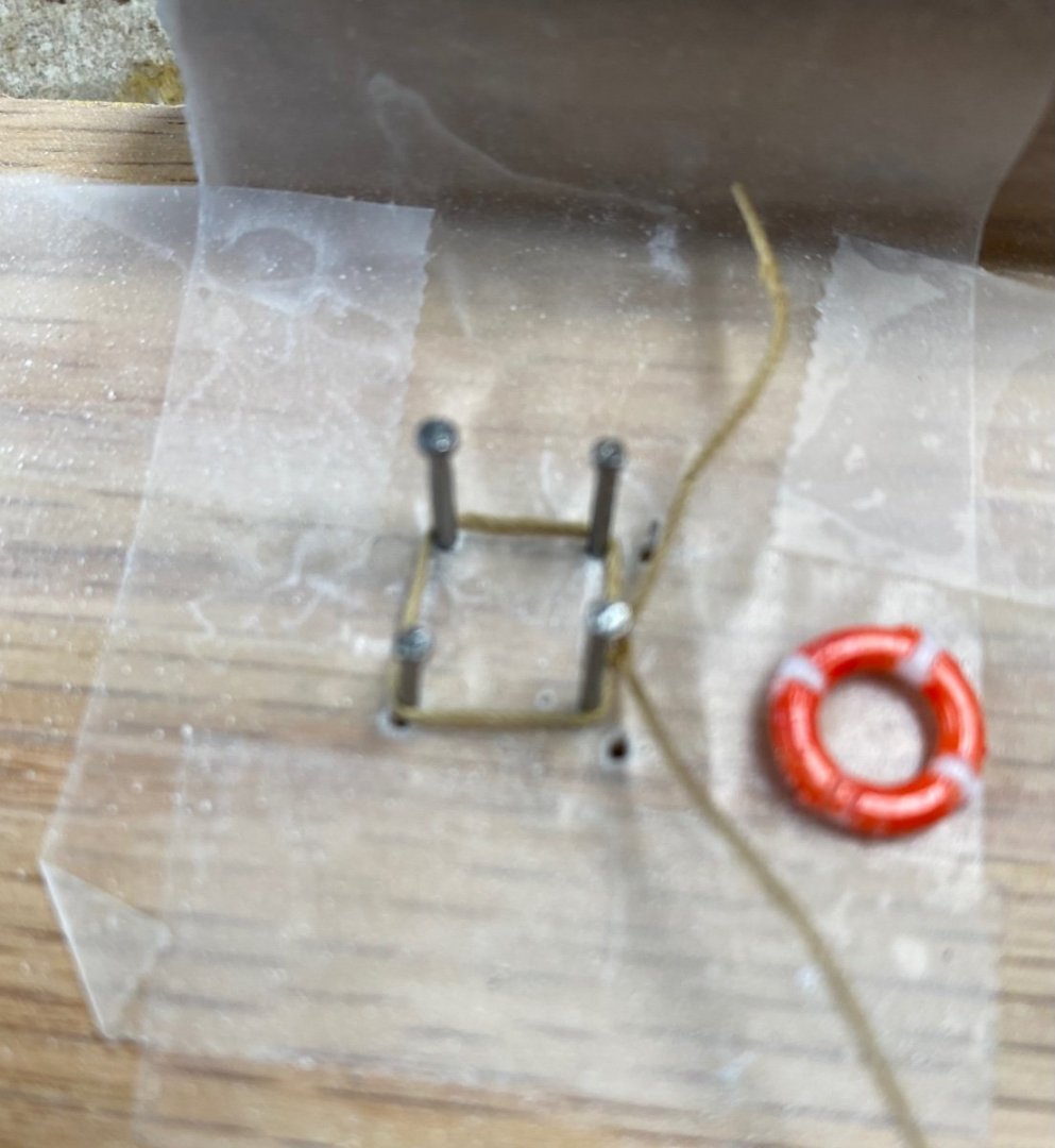
In one of my previous posts I presented my method for creating the fire buckets that are shown on the boiler casing. The bucket that I did for testing was too big, so I used a smaller brass tube. This is the first one. This is the whole batch and the holding racks And the the final product: Before installing them I am going to simulate the legs of the racks and fill the bucket of some very fine white sand (like the one we have here in Florida) I also started the detailing of the life rings. These life rings are 10mm dia and I wanted to add hanging ropes in the perimeter. For this I used a jig to lay the rope between the nails and then dropped the ring over and glued (CA) the rope in the marked four points. I will make four life rings using this method and will try to tie the rope to the rings at the attachment points by serving a line round the ring. (Excuse the poor focus in the photo)
-
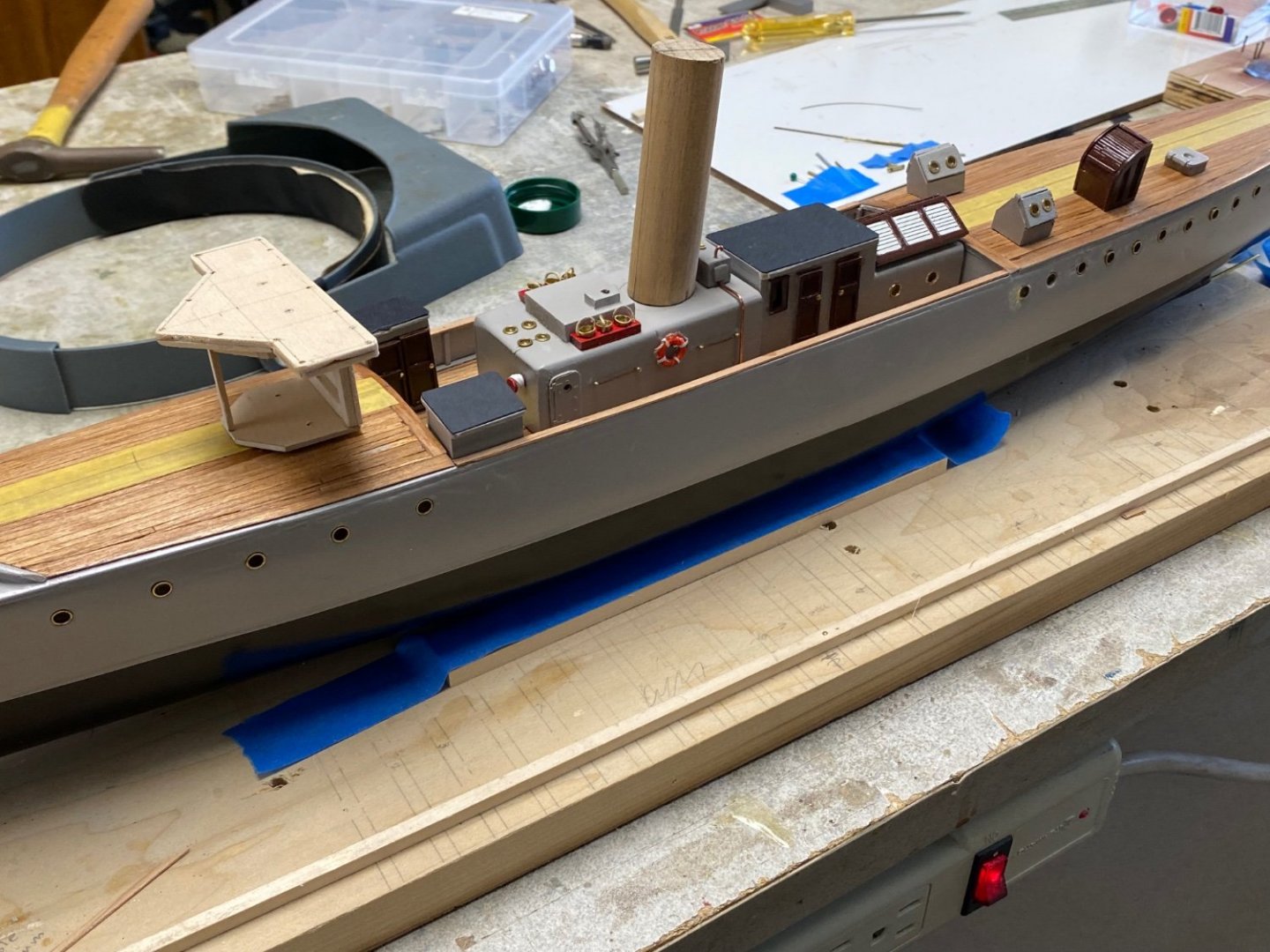
Holy cow, your ship looks incredible. We finally get to see the work in total. Love to se the forward view. Super WOW again
-
Thanks a lot Valeriy You have been a great teacher
-
Thank you Wefalck, I admire your precise work very much. I try to do the best I can with my shaky hands and my poor eyes. I think that the 1/64 scale is a small as I want to build in the future. For your information I am already researching my future project. I have two ships in mind. One is an armed trawler from the WWI period. These were both made with wood and/or steel hulls and were based on the British net trawlers. The other one is a 40 Ft fast armed motor pinnace name "Mimi"which has a very interesting story.
-
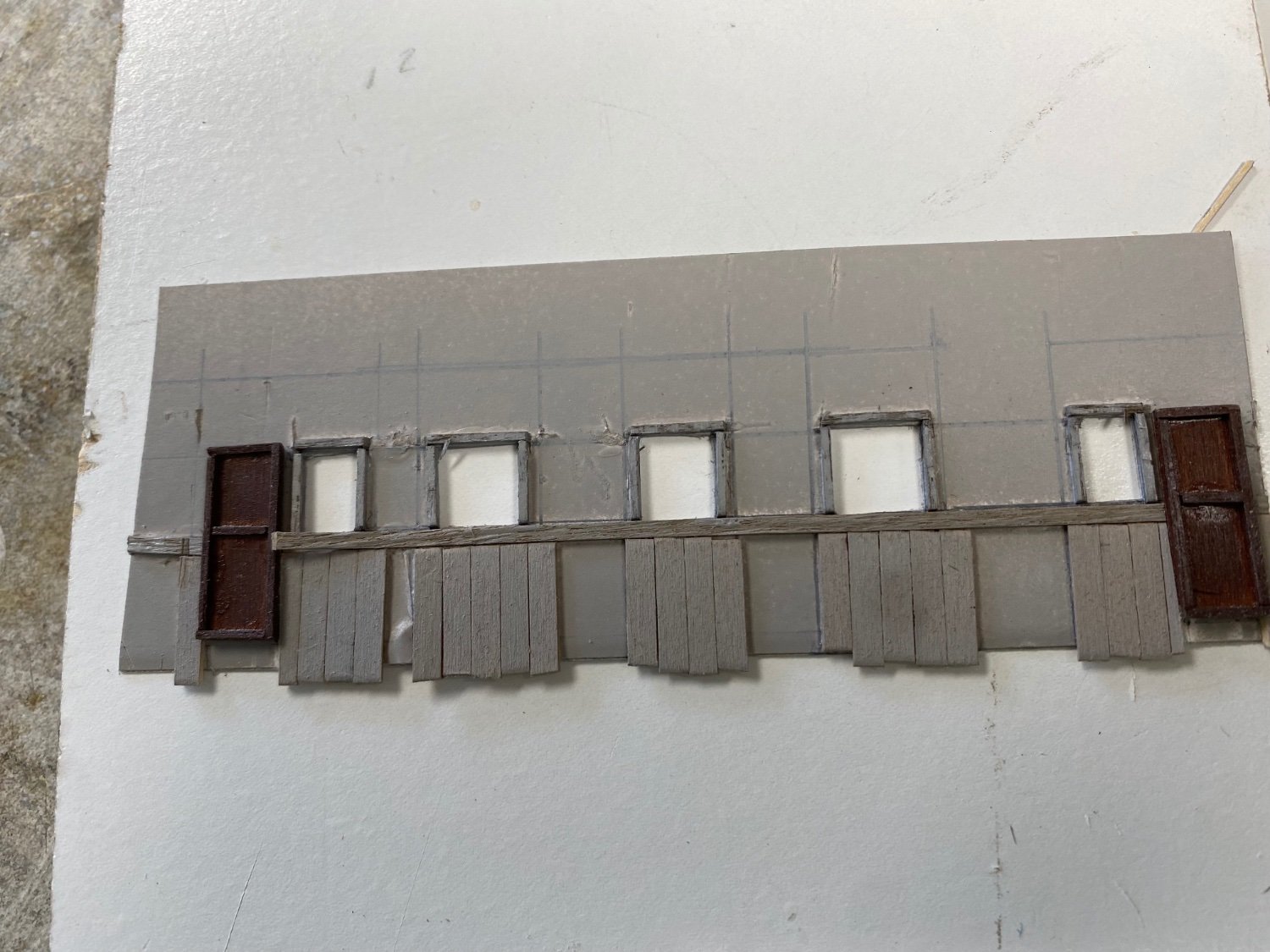
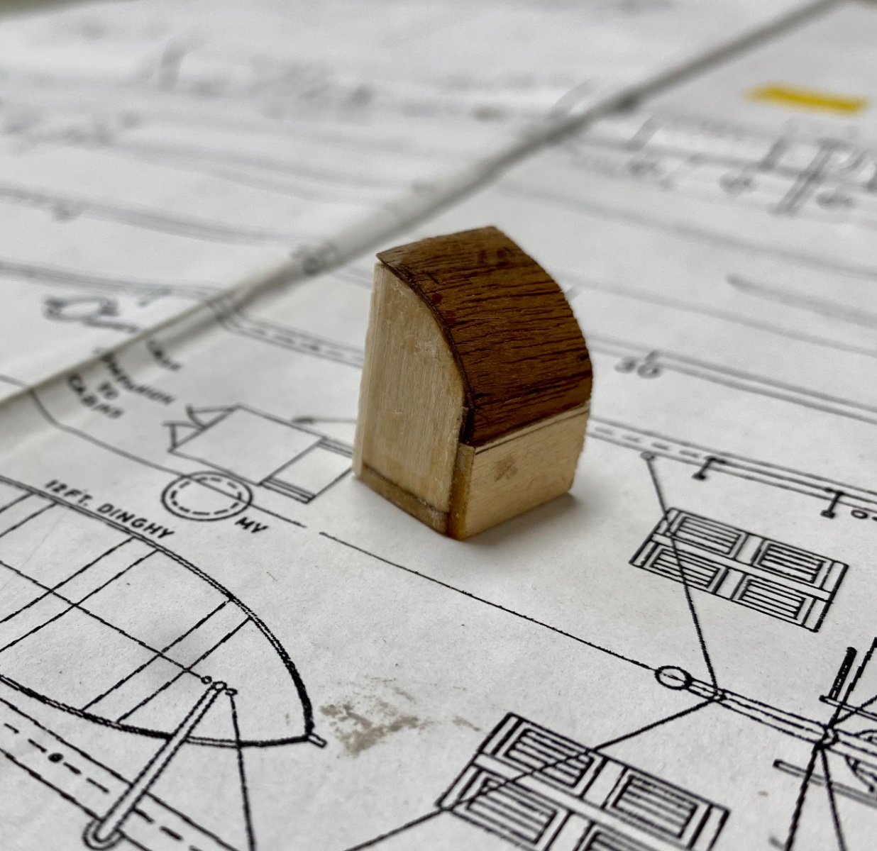
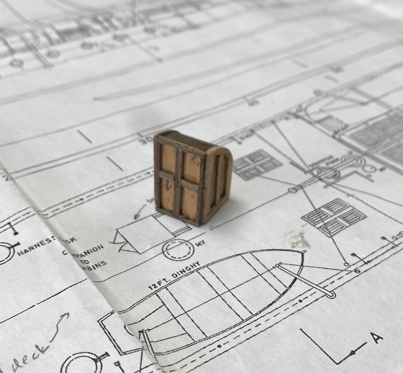
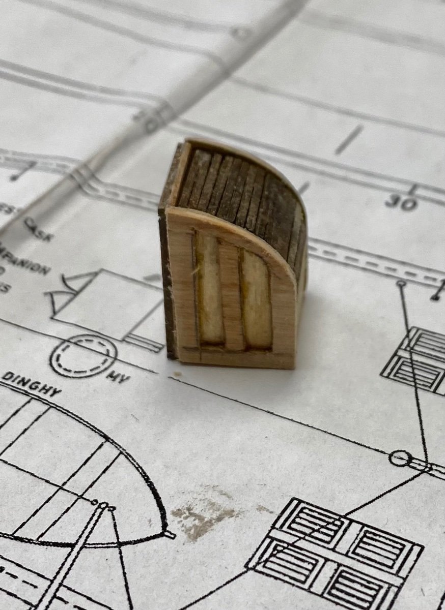
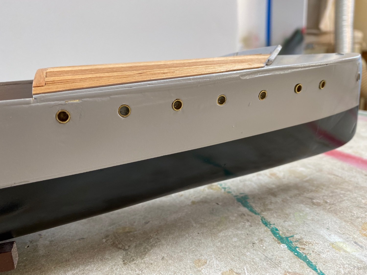
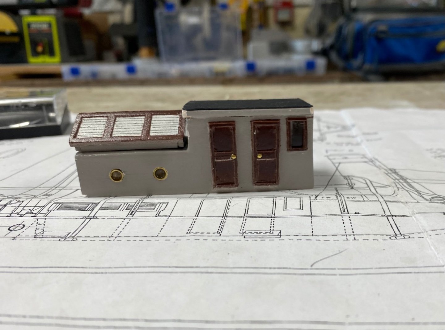
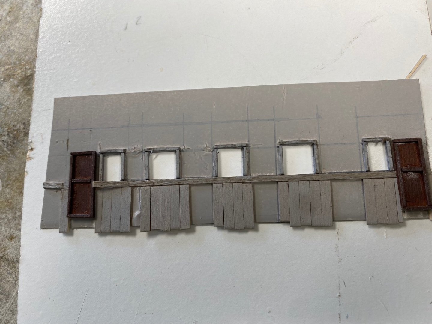
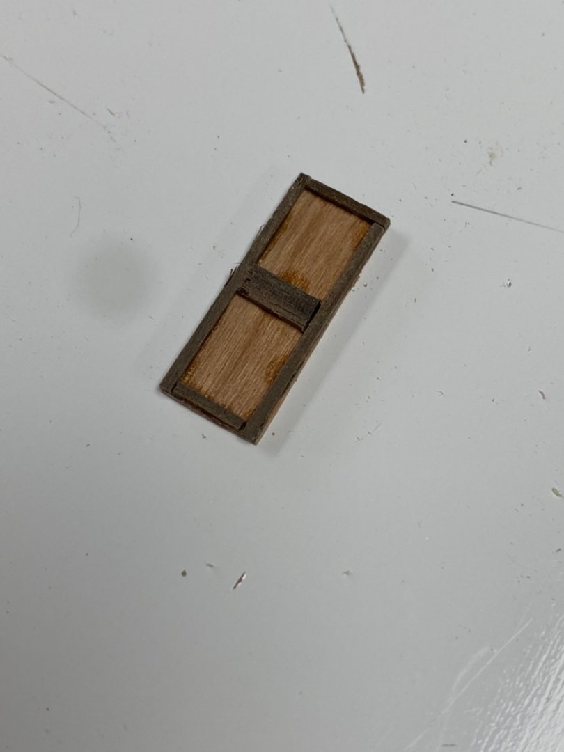
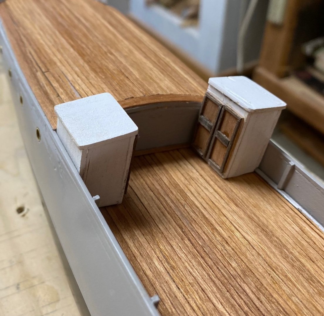
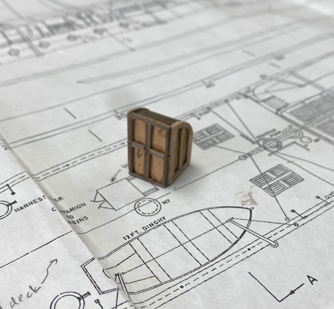
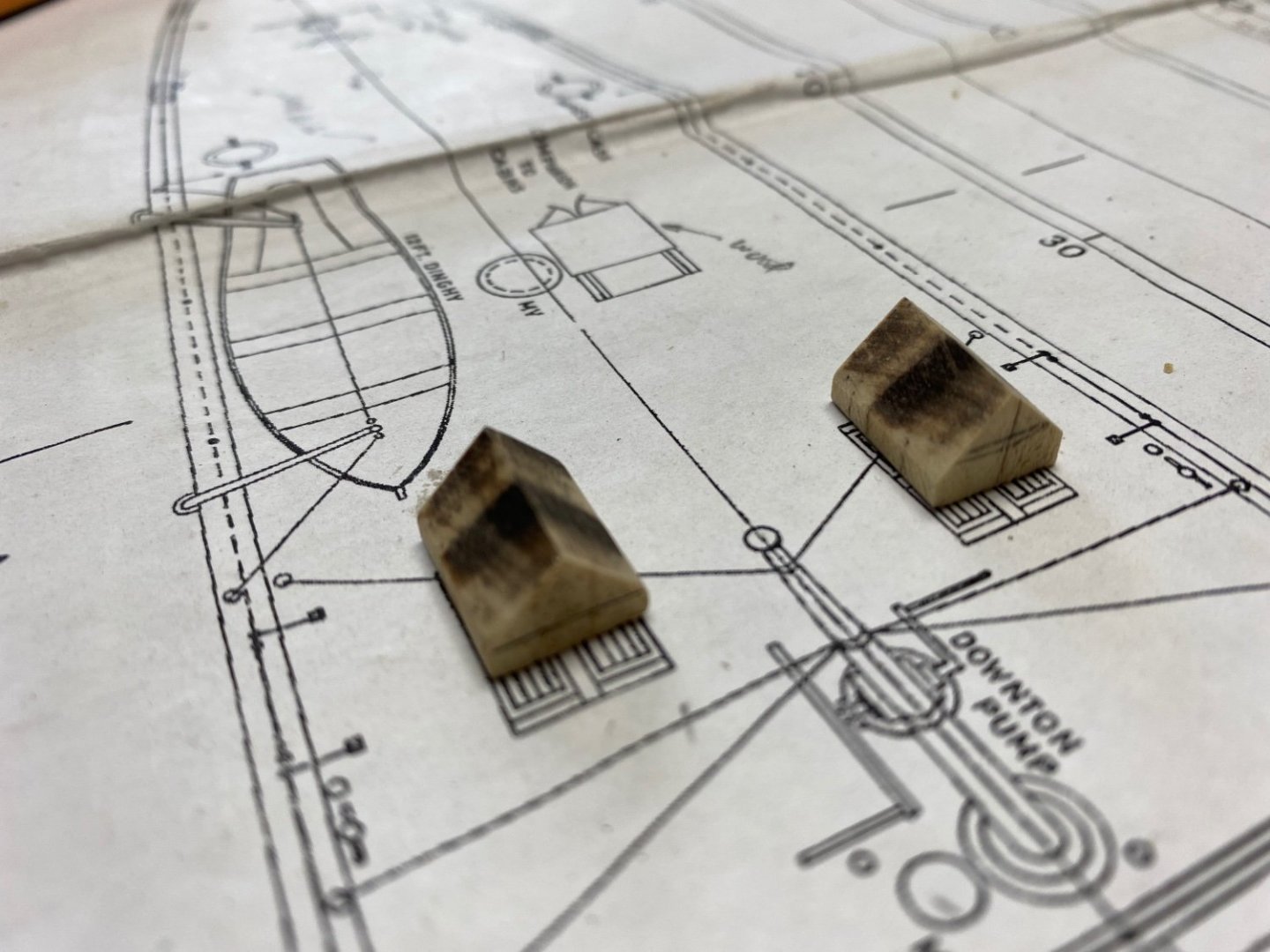
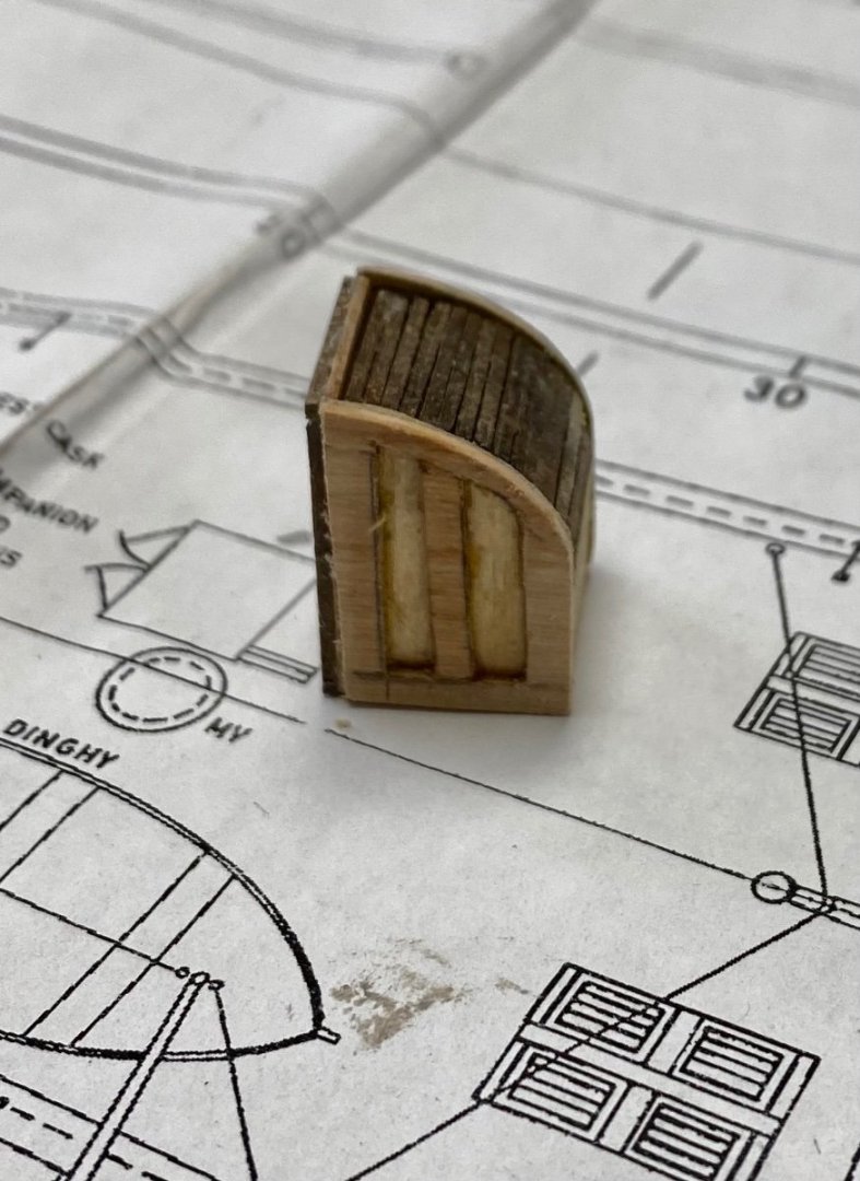
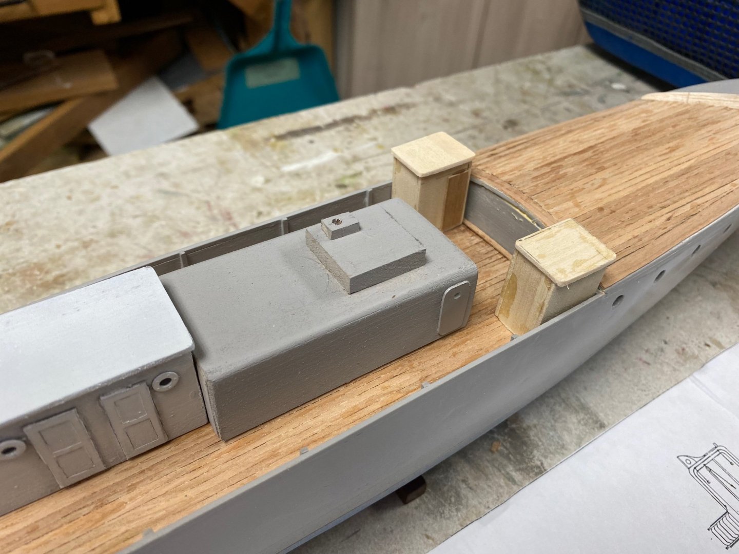
Have installed the propeller shafts and fabricated the supports but, due to my less than perfect symmetry and imperfections of in the hull, I had to order smaller propellers which are yet to arrive. In the meantime, I kept working on the deck accessories. Following is a photo of the heads (toilets) with the doors installed. I tried several methods to make the doors and finally decided on cutting the door out of 1/32" planks and glue 0.5 mm square strips frame. Later I will fabricate and install the hinges and the door knobs. Next came the companion ways I used a 1/64" plank to cover the curved area. Then , using the same procedure as the head doors I built the sides and front doors. Then using the 0.5 mm strips I laid the sliding hatch cover. Door knobs, handles and hinges will follow. Finally I cut the base for the small skylights out of solid pine. This kind of overworked my little MicroLux saw and burned the the wood in some places. I plan to make the frames and louvers out of the thin planks. Photos to follow. This project have been extremely rewarding to me as I venture in the fabrication of these miniature pieces. My results are far from the accuracy of the fabrication by Wefalck and Valeriy but my tolerances stop at +/- 0.5 mm. Thanks for watching.

-
Hope y'all had a great holiday. I did. Continuing my build, it was about time to remove the masking tape that protected the ships bottom while I worked on the deck planking. To my delight the waterline came perfectly delineated and the results show in the next picture. First time I use Tamiya masking tape for this job. I also installed the brass porthole rings that have been glazed with Gorilla glue. They came out all right but I had do a little of damage control with a wood filler wash. More pictures to show the progress to date. I continue working on the upper structures and started to use a mix media of cartuline and wood veneer to complete the trim of the cabins. Next I was looking on how to fabricate the miniature fire buckets. I tried using brass tubing been swaged with a punch. The one shown is about 3/16'' OD but the final set will be 5/32". And thats all folks! Thanks for watching and appreciate your comments.

-
First of all, thanks Wefalck for the tip to the Brazilian Museum. I will be contacting them to see about more information about my project. I do not speak Portuguese but I can understand their writing pretty well. Planking is completed and I have covered it with linseed oil and then finished it with a clear satin lacquer coat. When I was going to finish the upper hull I ran out of the paint I was using. The color is a Stone Grey Rust-Oleum Paint+Primer and for some reason was not available in my local stores. I went to five hardware stores to no avail, and finally ordered it online. While waiting for the paint to be delivered, I continued fabrication of several deck accessories. Unpainted are the crew heads and paint locker. Next I took my Unimat out and made, what I consider my microscopic mushroom vents. The paint was been delivered today but I will be taking a break for the Christmas activities. So, I wish y'all a very happy and merry Christmas.

-
You never fail to amaze me. On my Amapa, I am working at 1/64 scale and I am having trouble with pieces smaller than 1 mm. I Don’t have the right depth perception while using magnifying goggles and my hands tend to shake proportionally to the magnification. You are a master.
-
Truck ding aside, that is a fabulous piece of furniture and will sit perfectly with Magenta on its top.
-
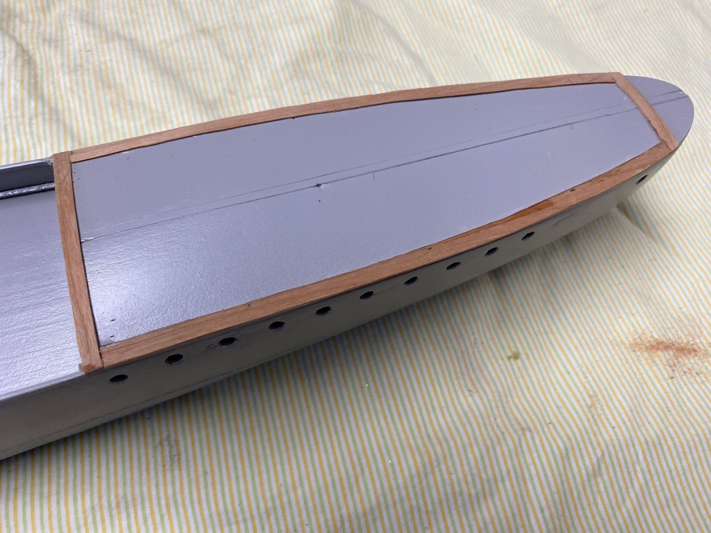
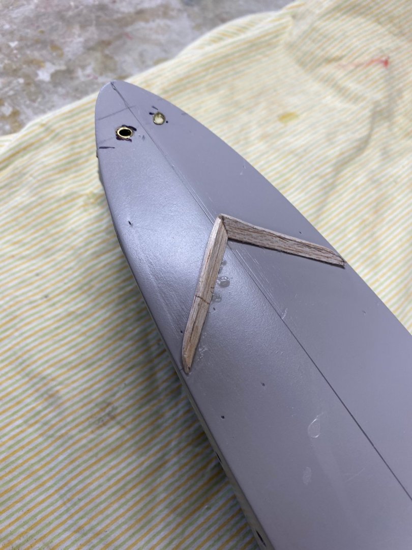
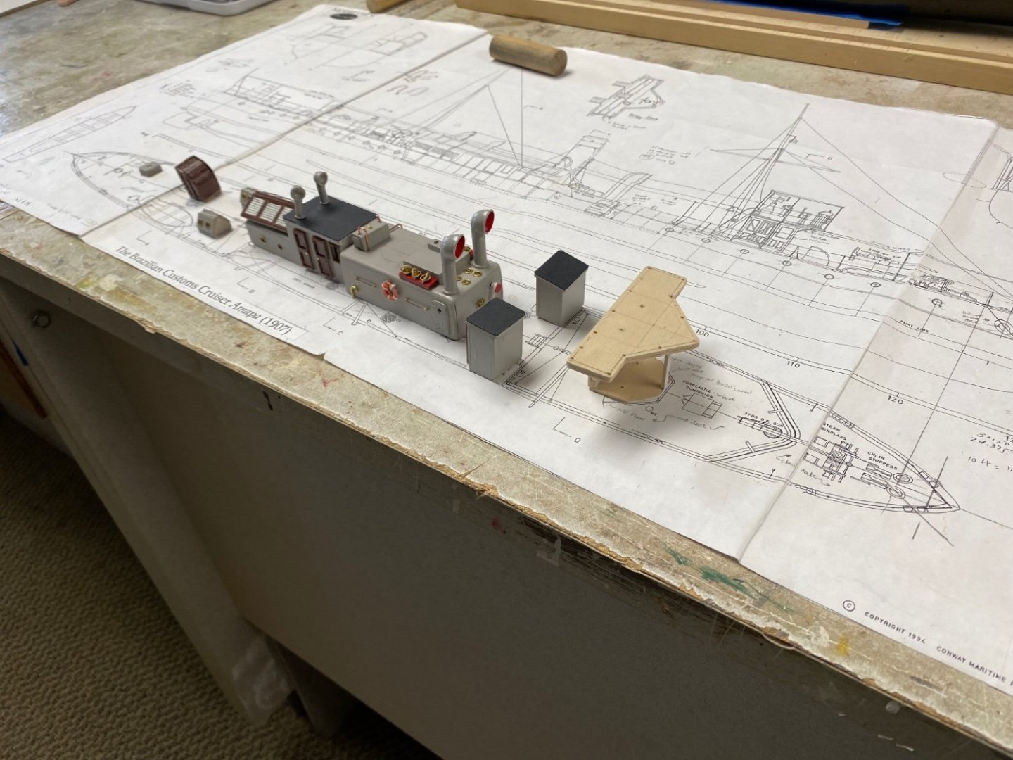
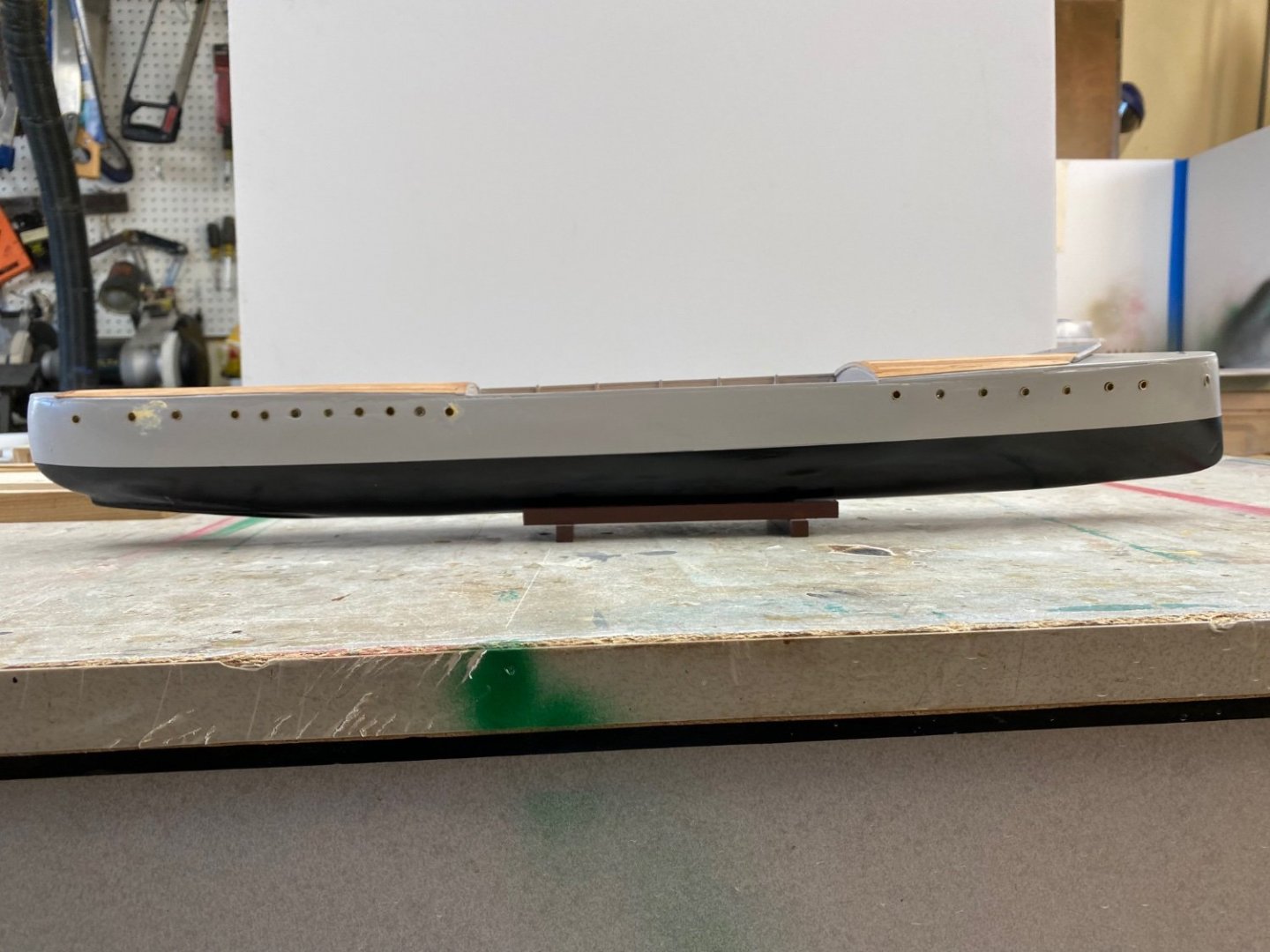
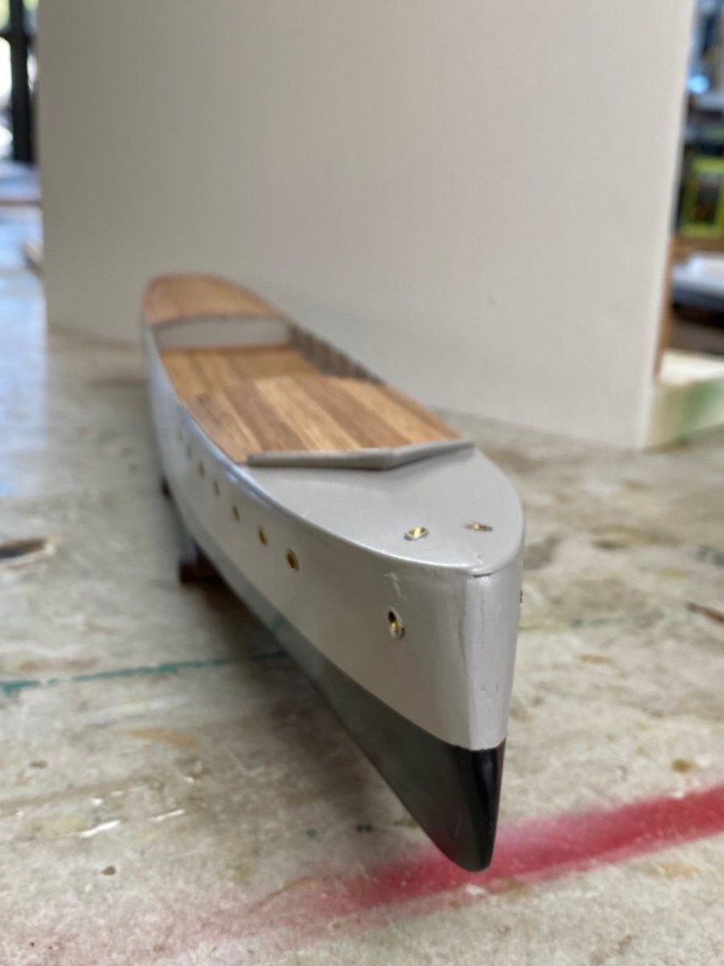
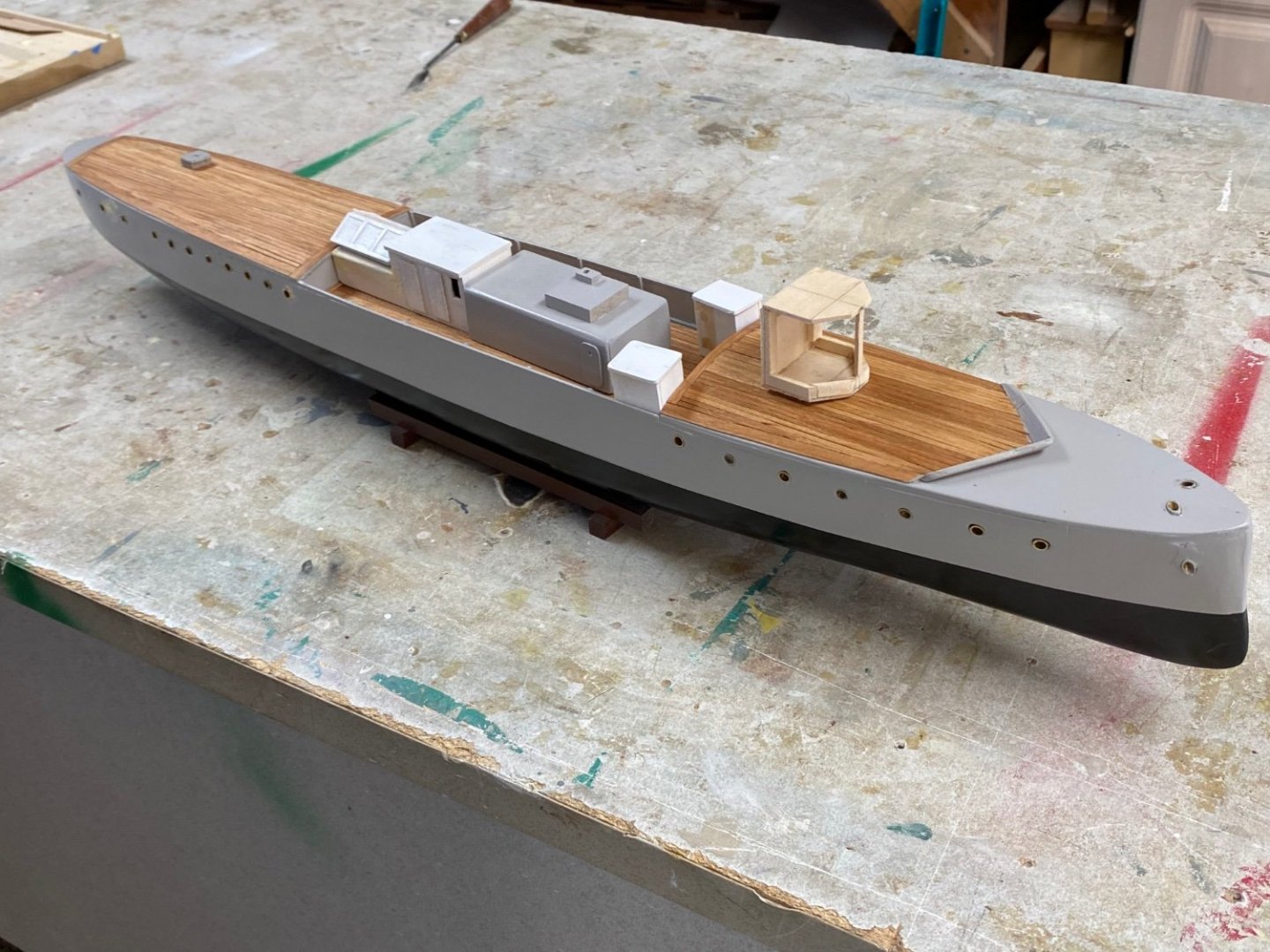
After looking at the information that Valeriy found, I saw that the Monthon had the whole deck wood planked. So I decided to go that way. Started by laying the waterway on the aft deck. Also decided to leave the fantail un-decked. The plan is to set grating in this part of the ship. The railing stanchions and the mooring gear will be sitting on the waterway. On the forward deck there is a wave dodger in front of the gun. This took a little thinking for its fabrication on account of the multiple angles but the problem was solved using hard balsa and sanding nail files. The results was an acceptable dodger. The plan is to leave this forward deck without planking to mount the anchor winch and its accessories as well as the forward mooring gear. The un-planked deck areas will be painted a darker grey as well as some of the superstructure roofs. I am still undecided about the the color of the stack. Will appreciate your ideas. Ships on the old "White Fleet" were white and buff but this one (1907) is a little past that time, more a pre WWI, and the base color is a "Navy Ship Grey". Thanks a lot for you likes and comments.