HOLIDAY DONATION DRIVE - SUPPORT MSW - DO YOUR PART TO KEEP THIS GREAT FORUM GOING!
×


modeller_masa
-
Posts
950 -
Joined
-
Last visited
Content Type
Profiles
Forums
Gallery
Events
Everything posted by modeller_masa
-
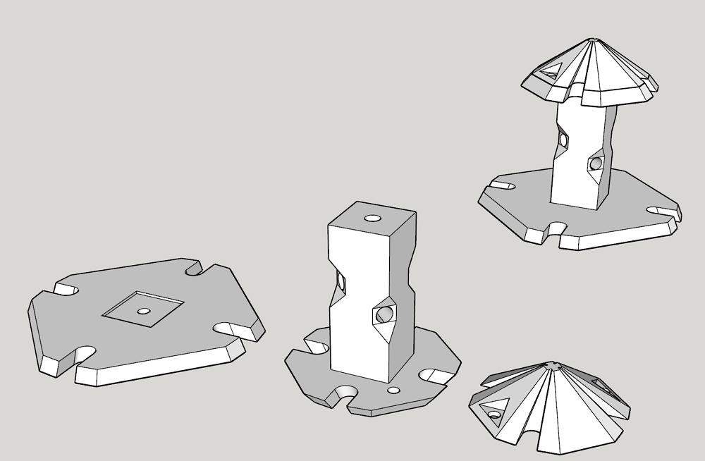
The next project was designing thread unraveling machine. I wanted to extract thinner yarns from 2-stranded commercial thread. The unraveling machine is essential to get the best of the best. The prototype didn't work well. 😂 Invention is a tough way.
-
I experienced some serious issues with the Rope-Rocket-structured machine. When I tried 5 meter long (14 feet) rope, the quality of the rope wasn't equal because of uneven tension on the threads. According to the manual of the Rope-Rocket, proper work length starts from 10~13 feet = 3~4 meter. It is time to go to plan D for longer rope. Olha Batchvarov's video shows how the plan D ropewalk works well. I made and printed the manual laying track. That' s the end of plan D construction. : ) When I ran the first plan D ropewalk, I was surprised by the difficulty. When I run the machine, I have to move the manual laying track evenly. If not, the quality of rope fluctuates. It implied that I should build a new drive system - rail, carrier, and tractor motor - for the laying track! Now I understood why Olha Batchvarov gave up to produce and sell custom ropes. Rather than constructing more advanced factory, I'll step backward and stick to Plan C : Rope-Rocket structured - ropewalk. Thank you for watching my journey on rope. I hope my post helps people who are seeking more advanced ropewalk machine.
-
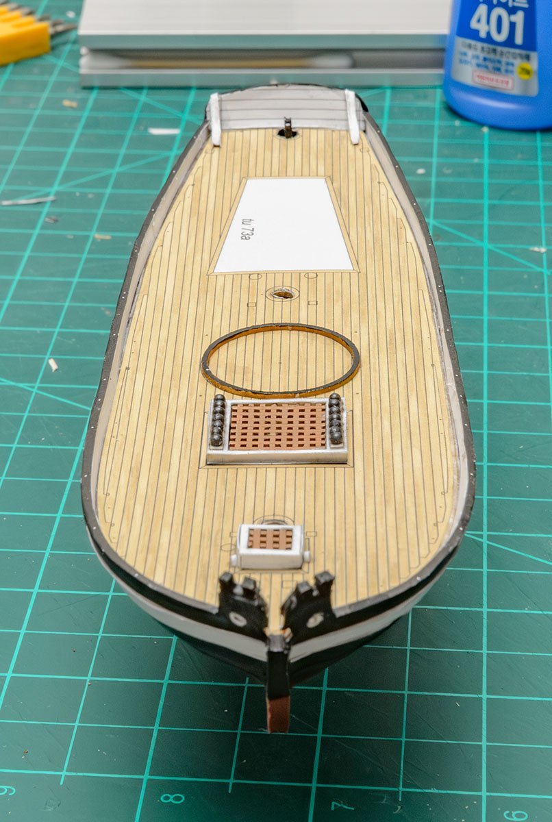
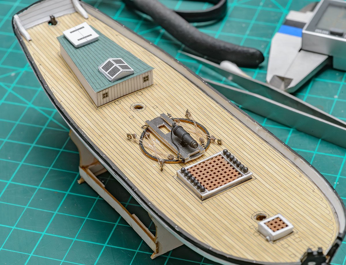
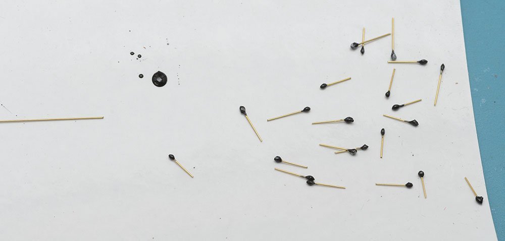
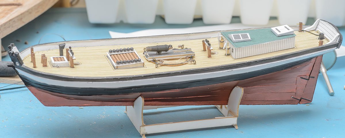
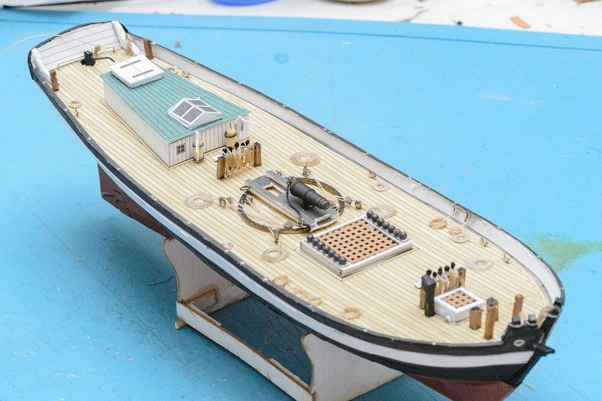
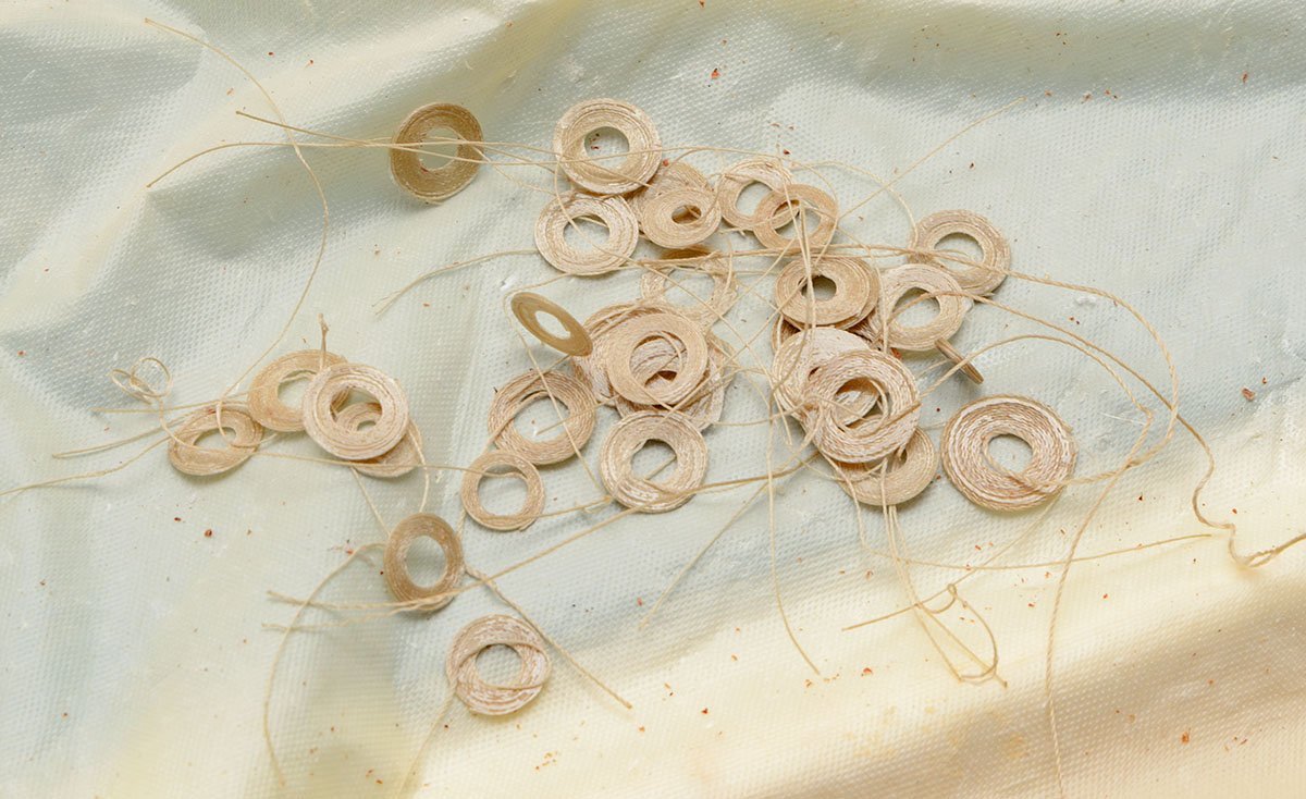
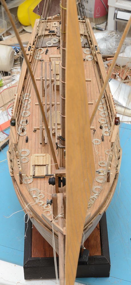
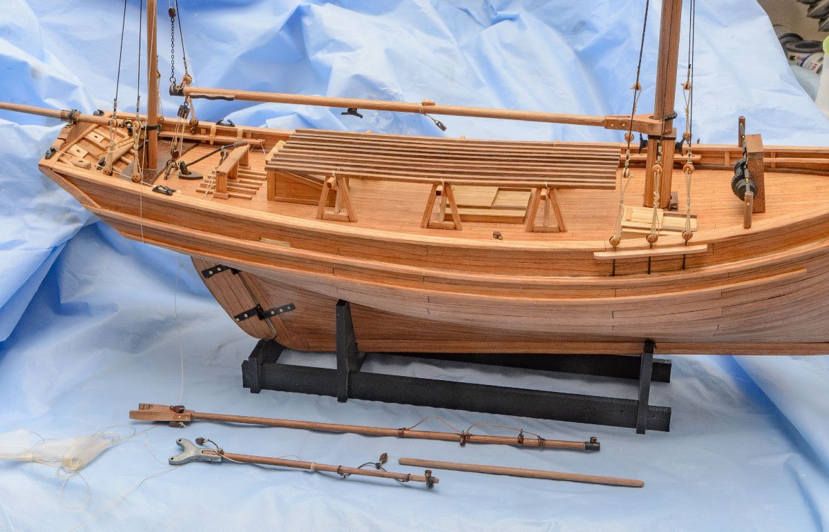
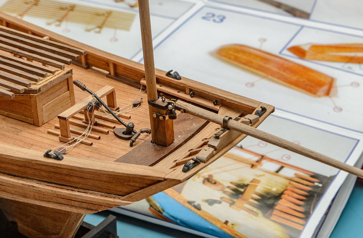
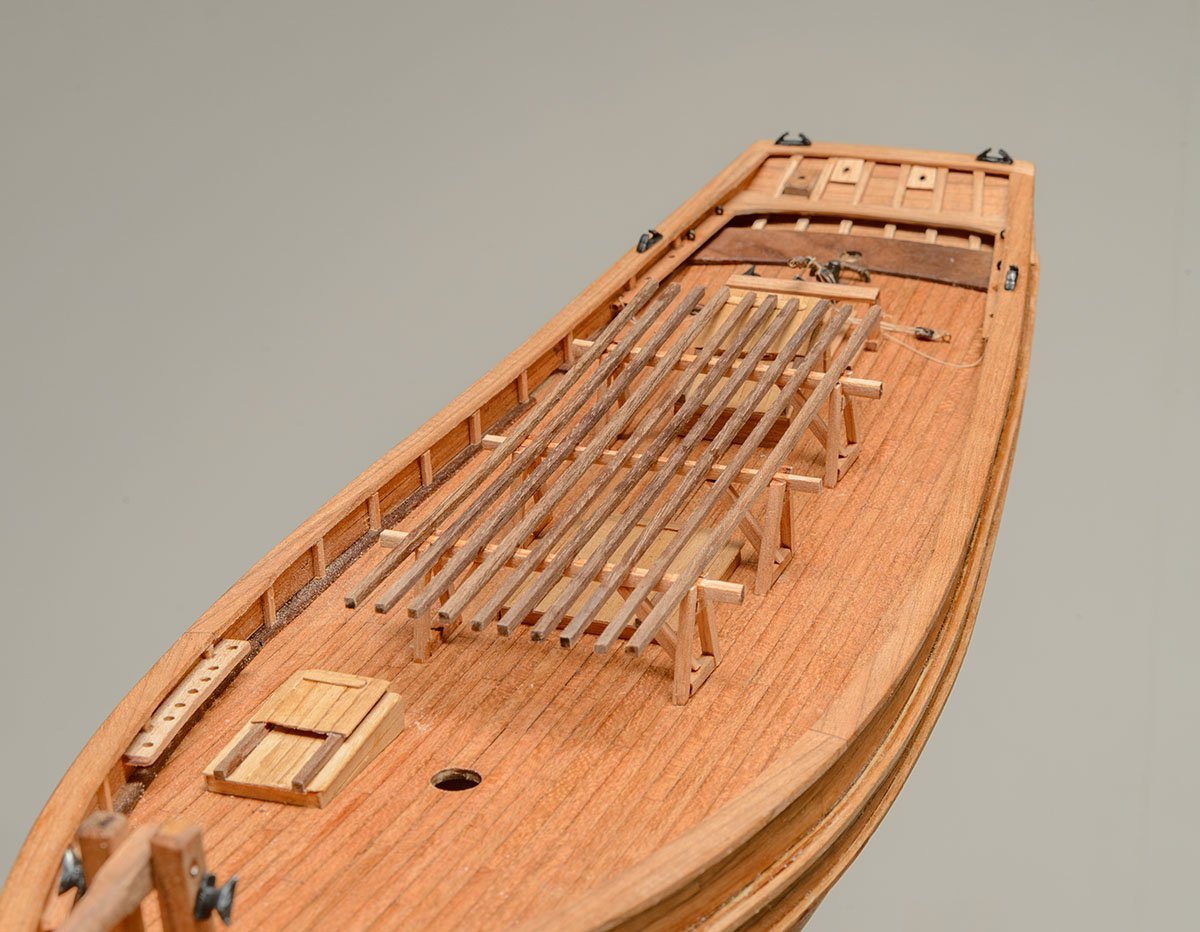
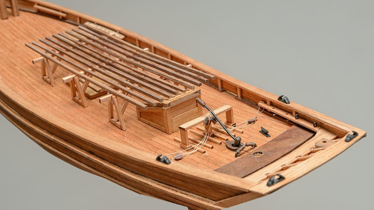
Nice to see you, Jsk. I prefer to learn new details by fast building, so please forgive the quality of my work. I made some mistakes on the canon, but I won't fix them because there will be a chance to build another kit in the future. I made micro sized belaying pins using black CA glue. The deck fitting is done. This time, I finished fake rope hanks before rigging. The next step will be building masts and installing standing rigging.
- 16 replies
-
- 5
-

-
- Revenue Cutter
- Seahorse
- (and 2 more)
-
OcCre HMS Victory Limited edition
modeller_masa replied to modeller_masa's topic in Wood ship model kits
That was me 3 months ago. -
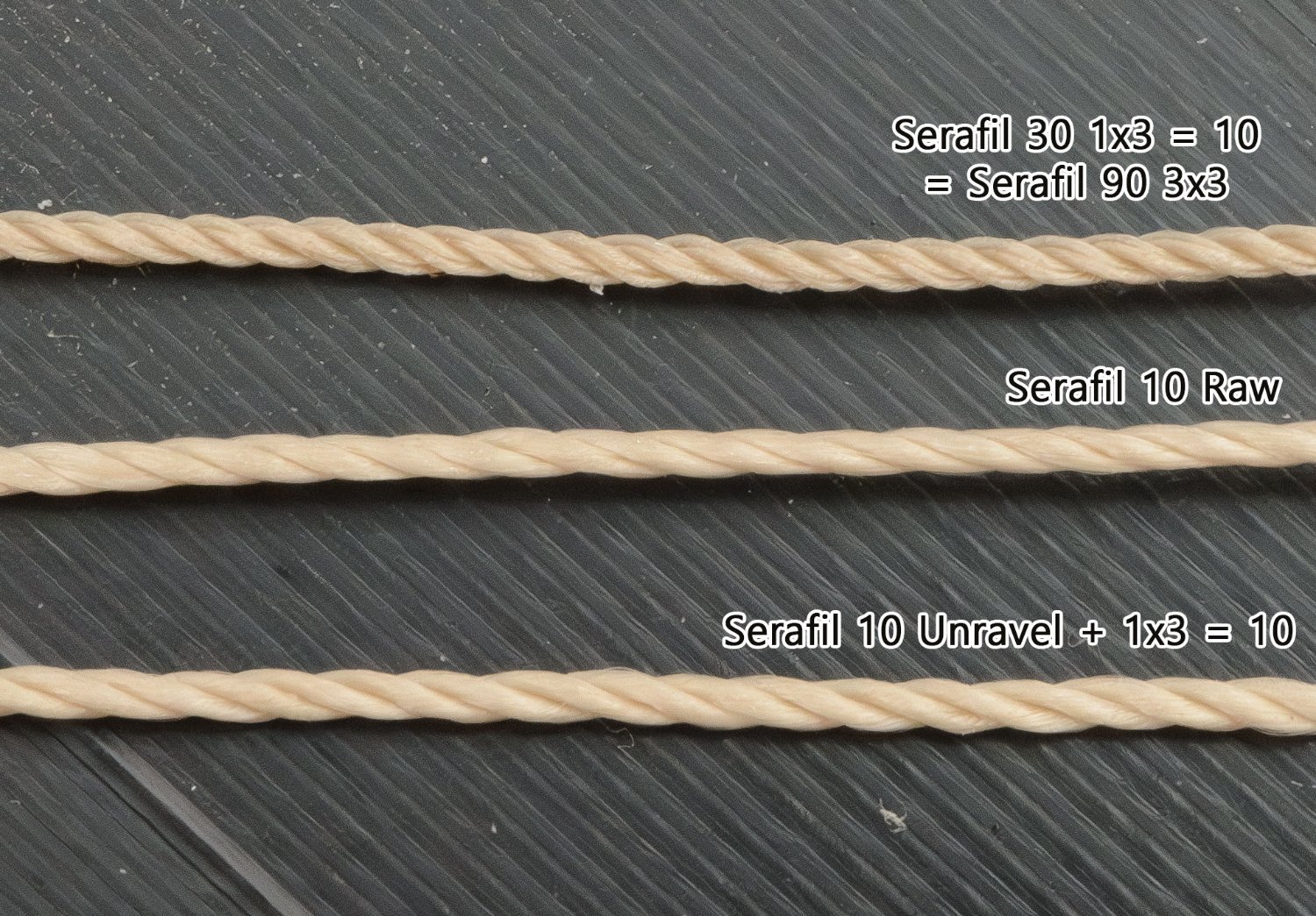
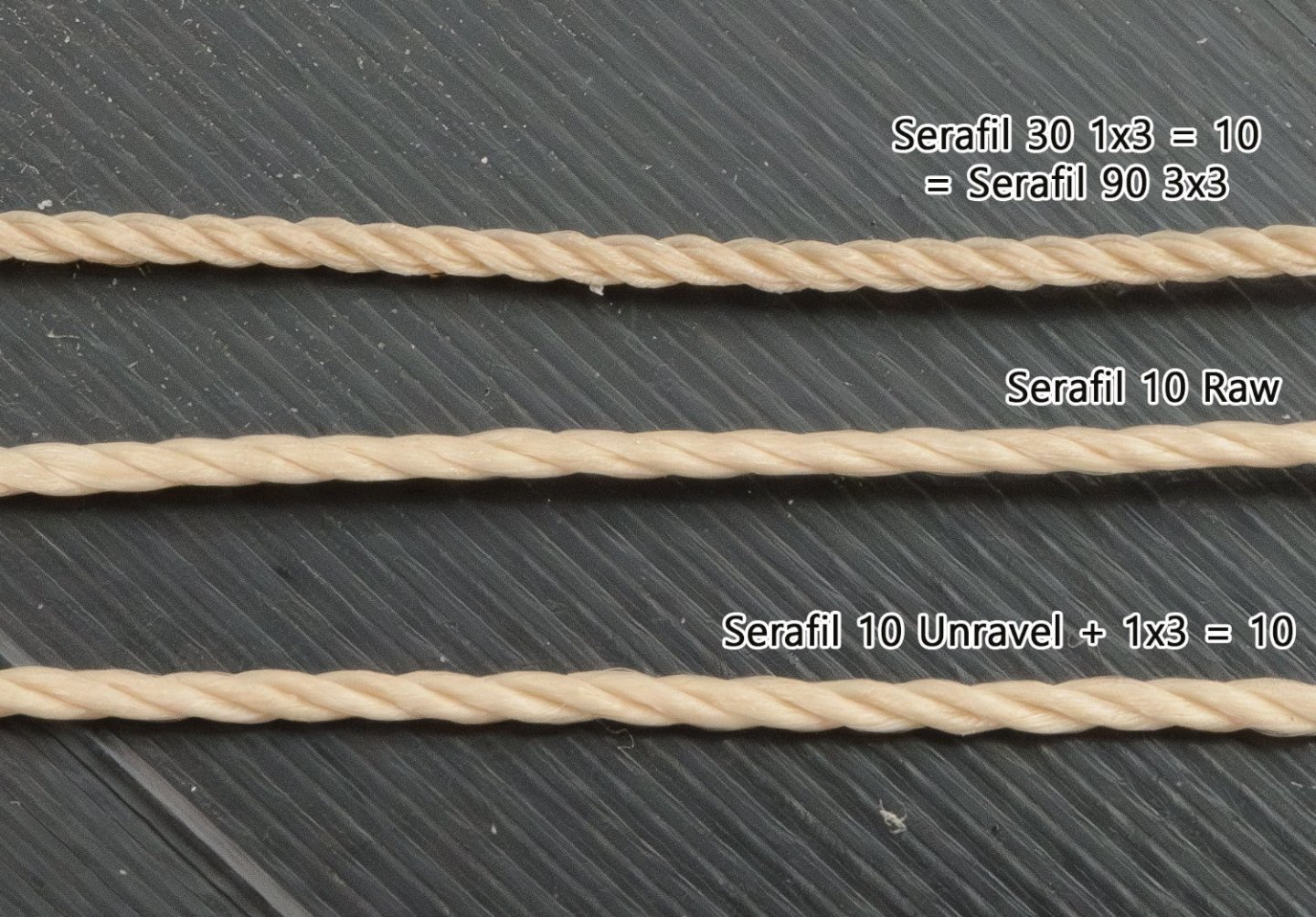
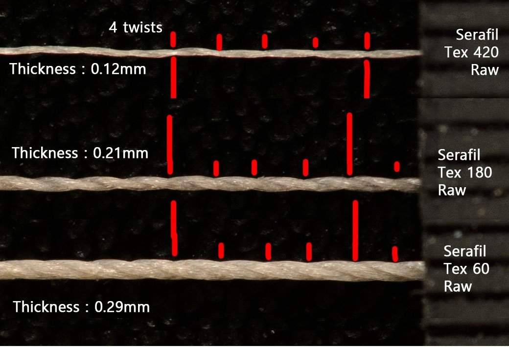
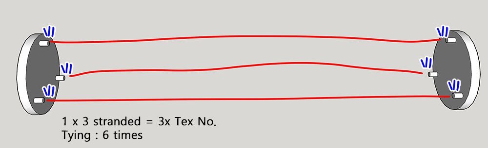
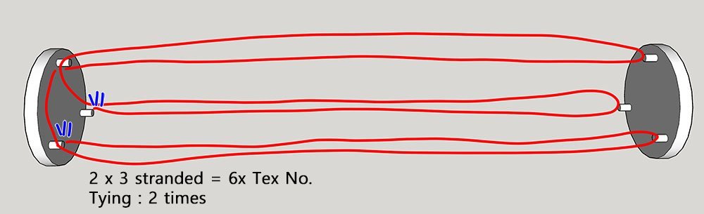
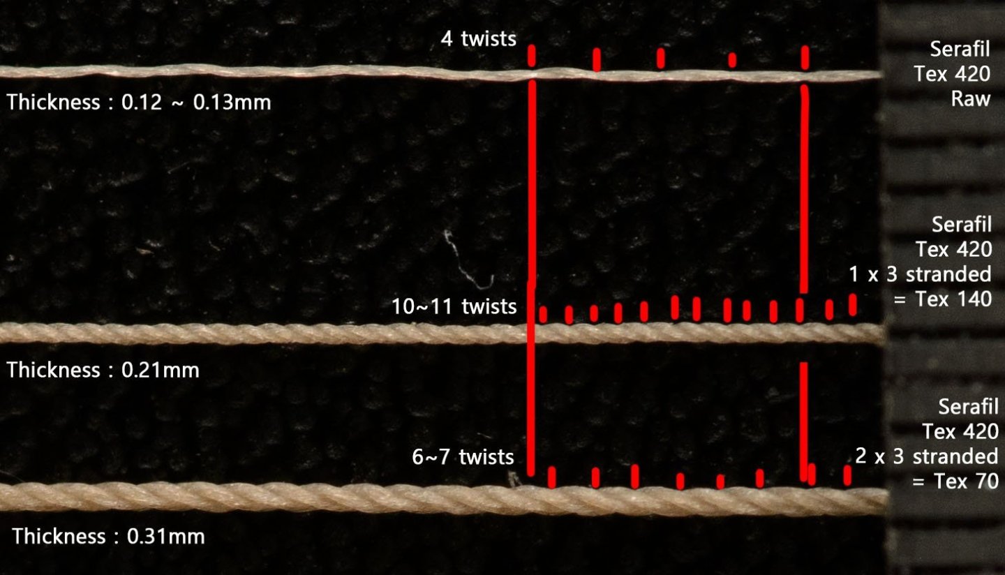
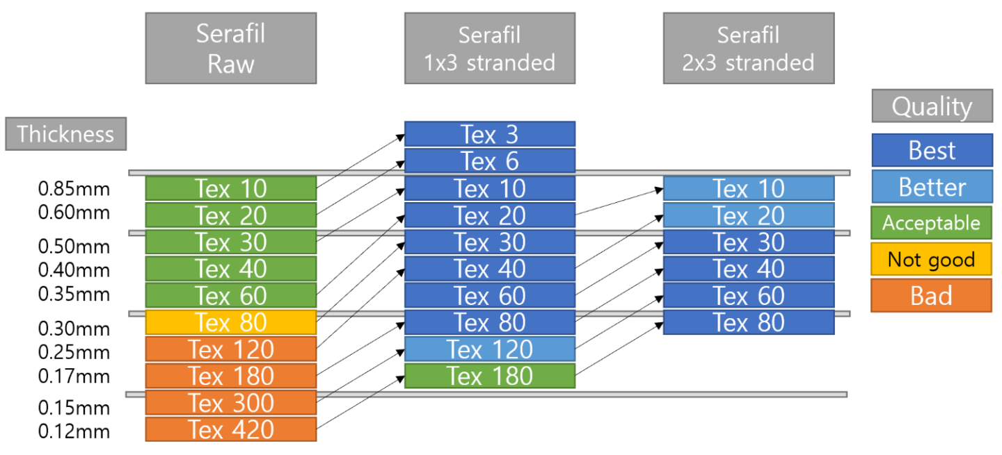
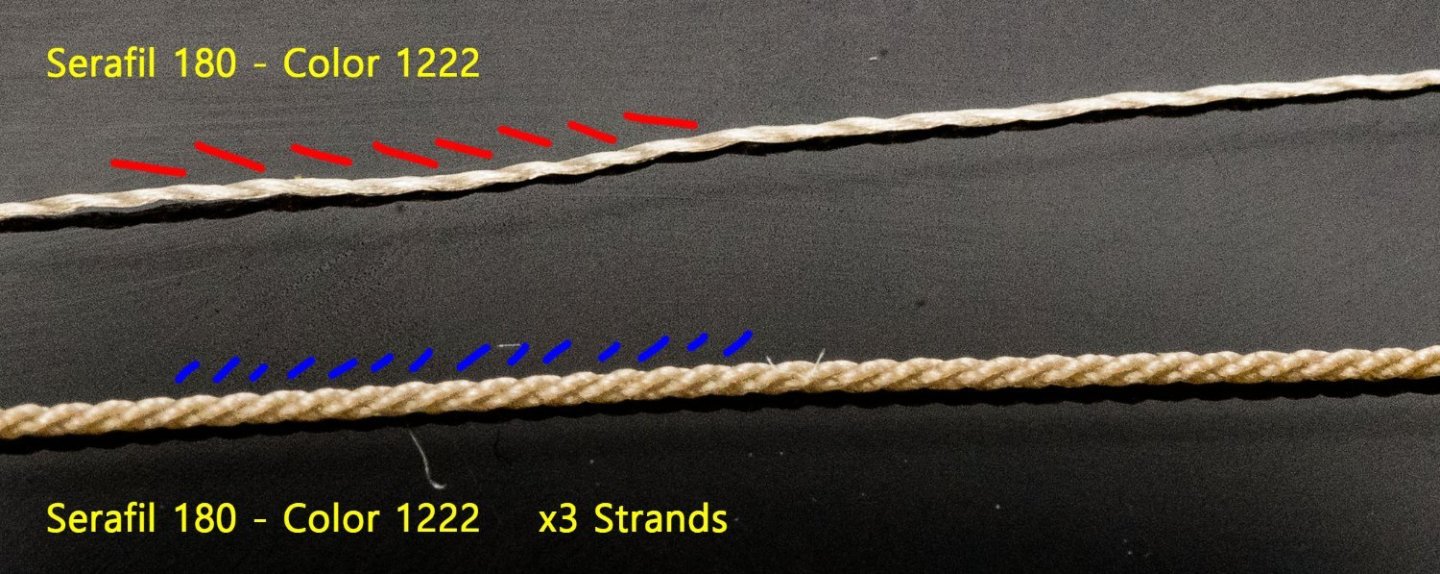
This picture shows why raw thread looks glossy and plastic like. While Serafil Tex 10~40 threads are really looking nice, Tex 120~420 threads are not so good for model work due to their relatively lower density. There are two ways to load threads on Ropewalk. The first method needs 6 knots, so it is relatively time-consuming and boring. It produces the best quality ropes. The second loading method is relatively easy and fast. Although the result is slightly blurred and soft, it still looks better than the raw thread. It shows the difference between the two methods. The middle one, by the first method, is perfect rope and has the highest density. The higher density makes rope slightly thinner, so the Tex number is more likely Tex 180. The bottom one, by the second method, doesn't have significant density, but its matte surface and slightly higher texture make it better than Tex 60 raw thread. This is a quick summary of the benefits of the ropewalk. I prefer the 2x3 method because it is the fastest and more fun to work with. Notice the Tex 120 and 180 threads by the 1x3 method. They are so thin that it is very hard to tell the difference between the ropewalk results and raw threads. I'll use Tex 180 raw thread when I bind blocks, which are not sensitive to rope details.
-
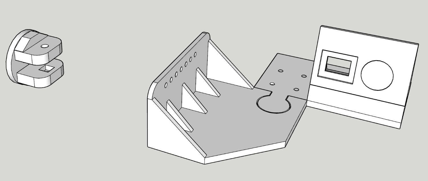
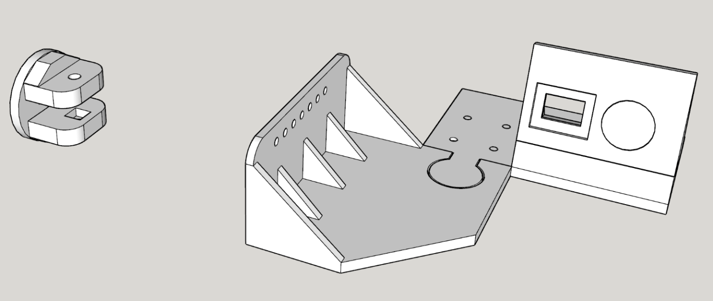
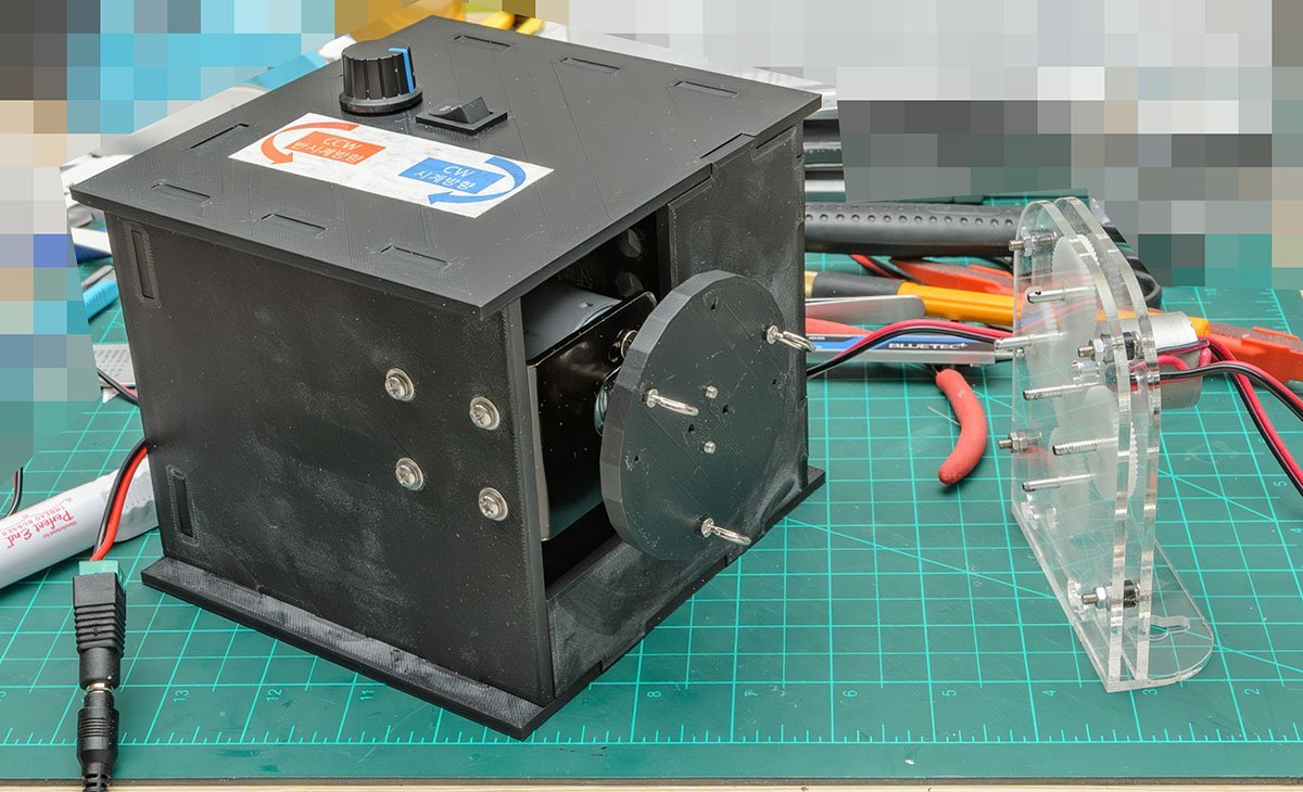
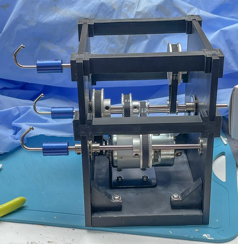
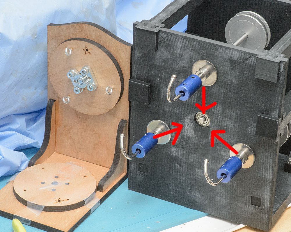
This is plan C. The right is a Domanoff VR Ropewalk, which I consider the best. Domanoff don't sell the oposite side (left) , so I made it motorized. Finally, I copied the structure of the Rope Rocket. Every part is motorized, which is faster and quieter than the wooden version. Is it practical and comfortable? Yes, but I found a new flaw in the work process. Before I run the machine, I need to load threads on the hooks. It is the most time consuming job in the entire process. How can I load raw thread faster? It is time to copy another awesome machine. The Olha Batchvarov's ropewalk has a better and more optimized work process compared with my motorized Rope Rocket. Thanks to previous work, I completely understand the structure of the OB's. The Plan D will be my ultimate ropewalk machine in my life...
-
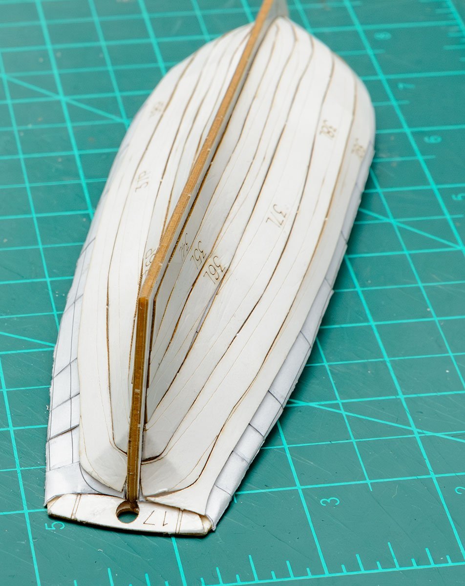
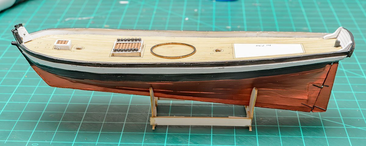
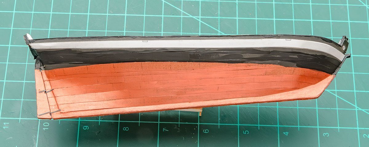
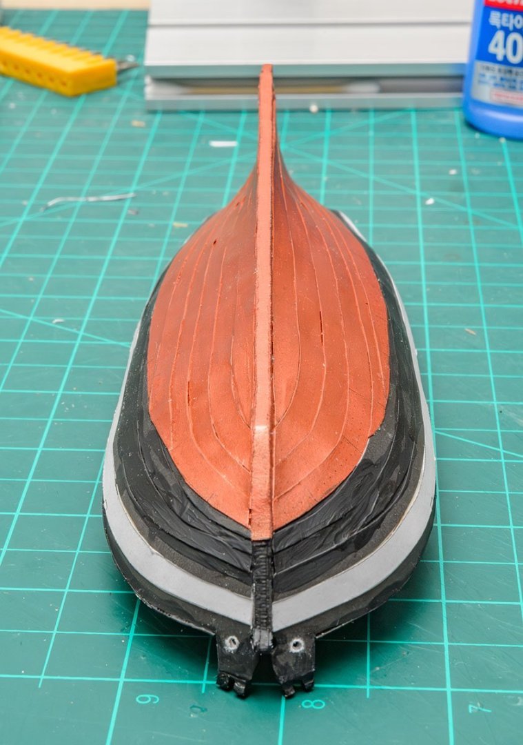
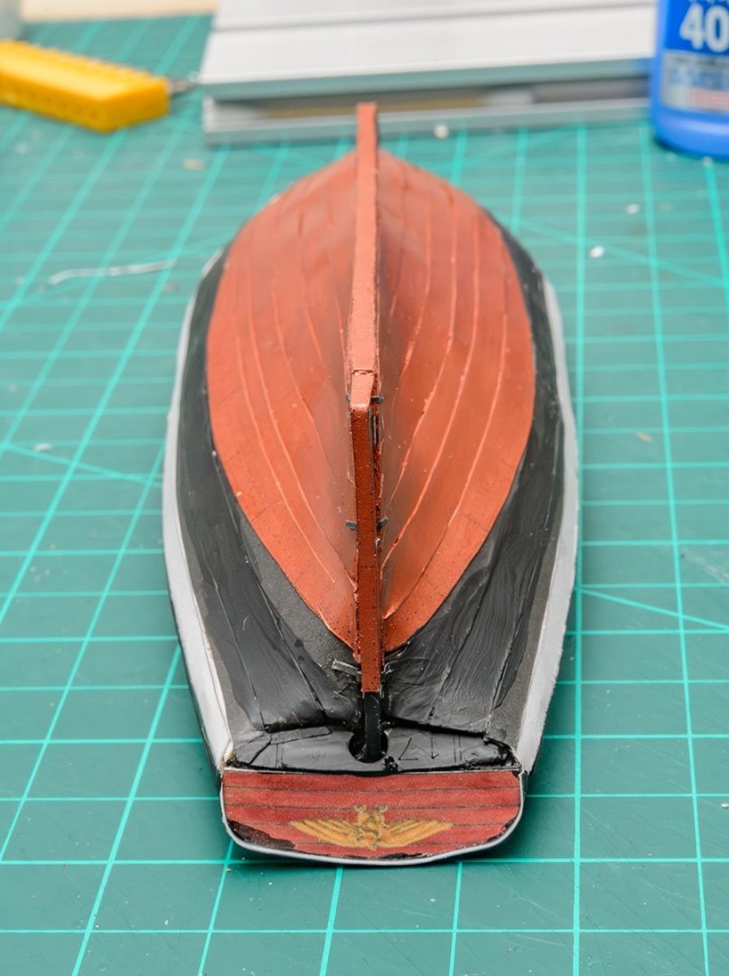
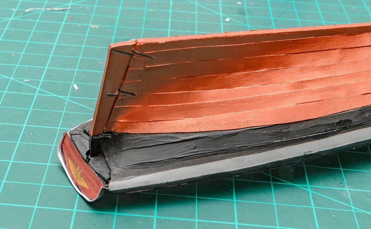
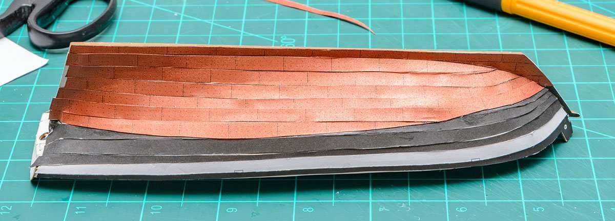
I painted gaps on the copper hull with Josonja burnished copper series 2 acrylic paint.

- 16 replies
-
- 6
-
-
- Revenue Cutter
- Seahorse
- (and 2 more)
-
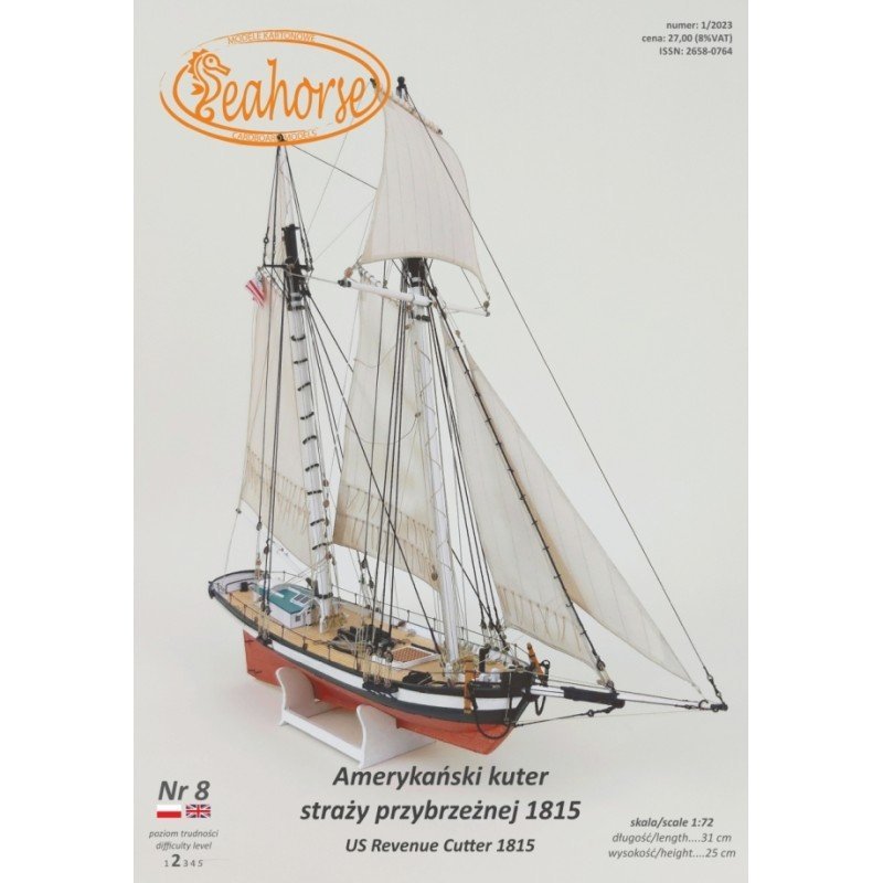
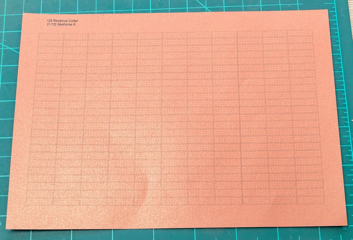
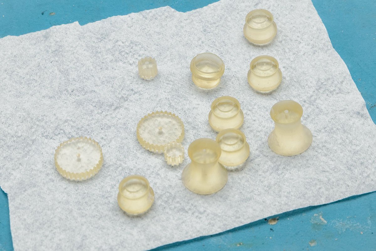
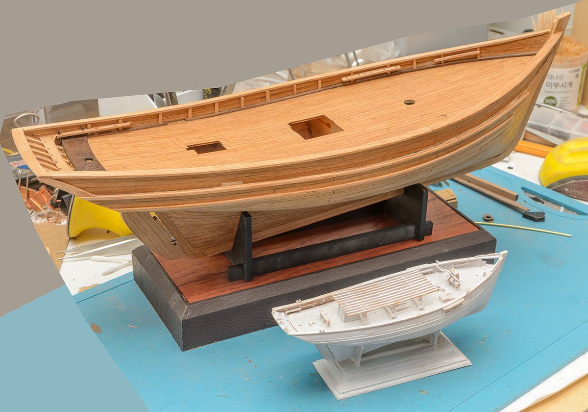
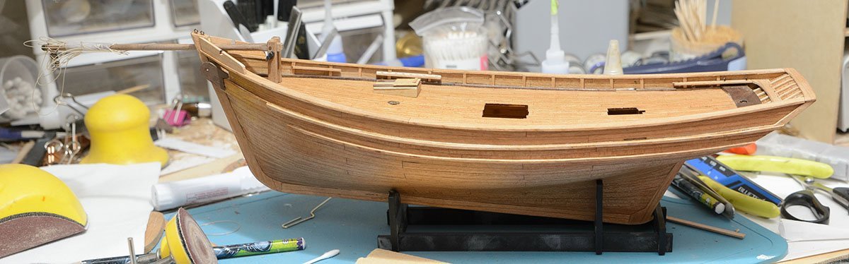
As before, this will be a speedy project rather than quality work. This kit was released a year ago, and I bought it with full options, such as laser cut hulls and 3D printed blocks and canons. You should check out other project by Jsk.


- 16 replies
-
- 2
-
-
- Revenue Cutter
- Seahorse
- (and 2 more)
-
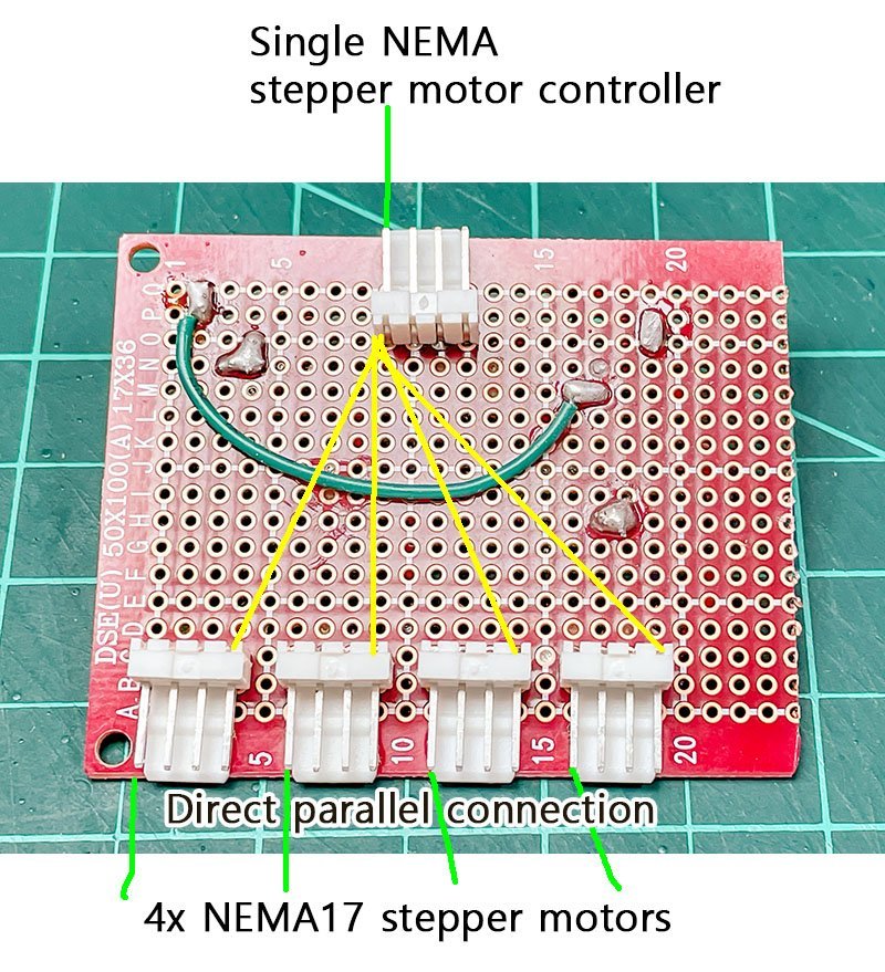
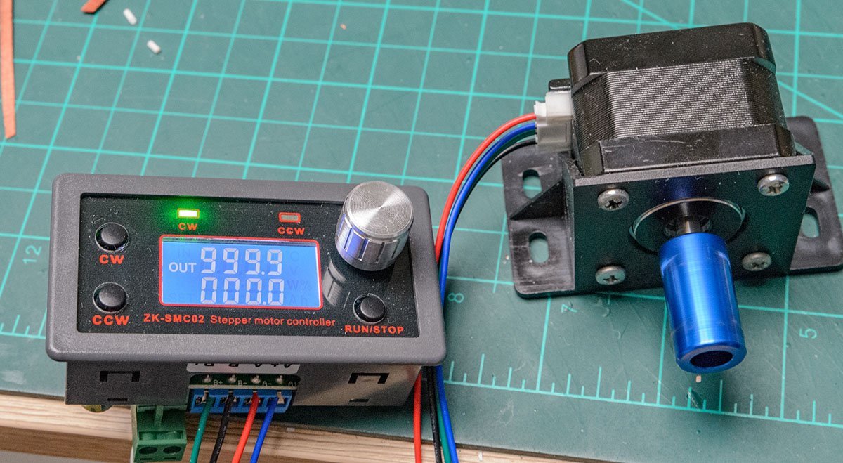
OK. I got used to another failure. I used a single NEMA17 motor controller and multiple NEMA17 stepper motors. I connected the motors in parallel. It seems to have been successful when I connected two NEMA17 motors. However, when I connected three motors, they were malfunctioning, such as in reverse directions or at different rotation speeds. I conclude that the simple parallel connection caused signal corruption. I may need to buy more serious circuits and do some Arduino programming. I pause plan B and go to the next plan C.
-
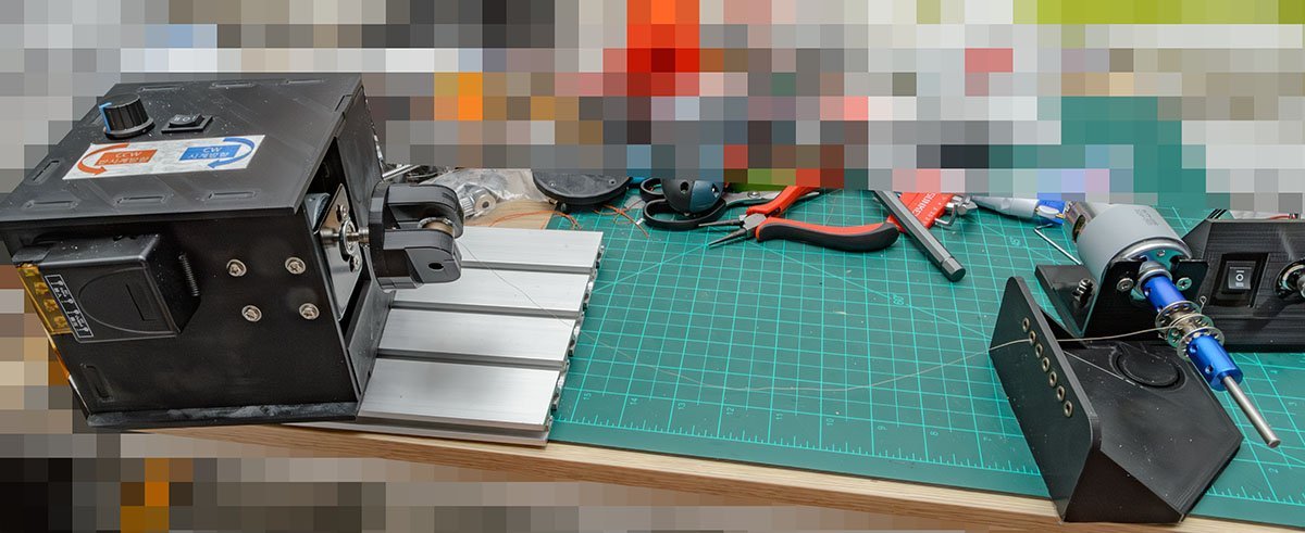
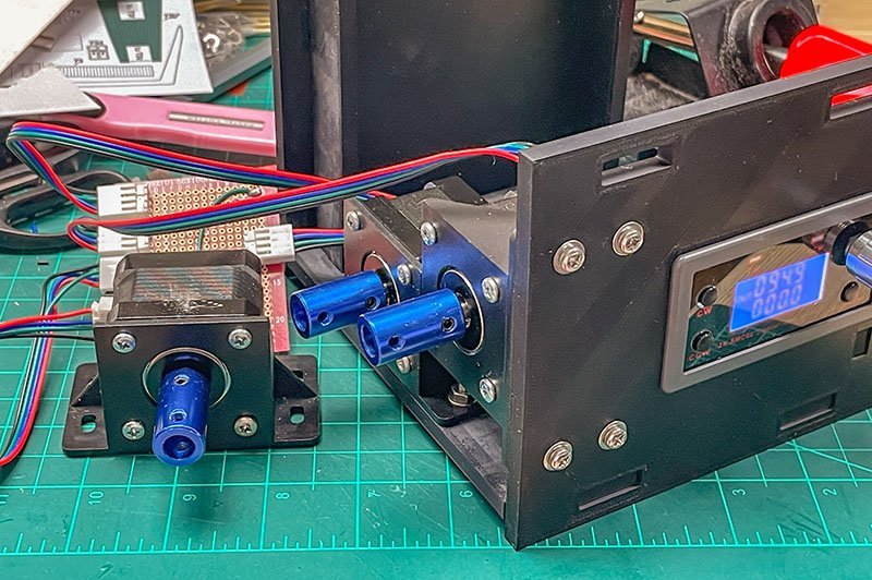
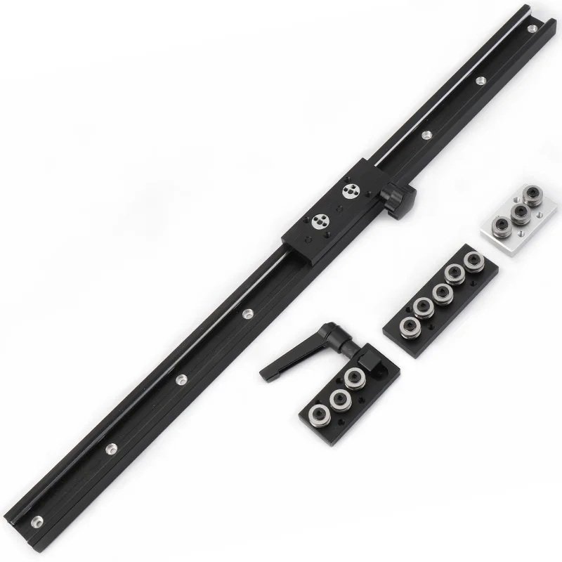
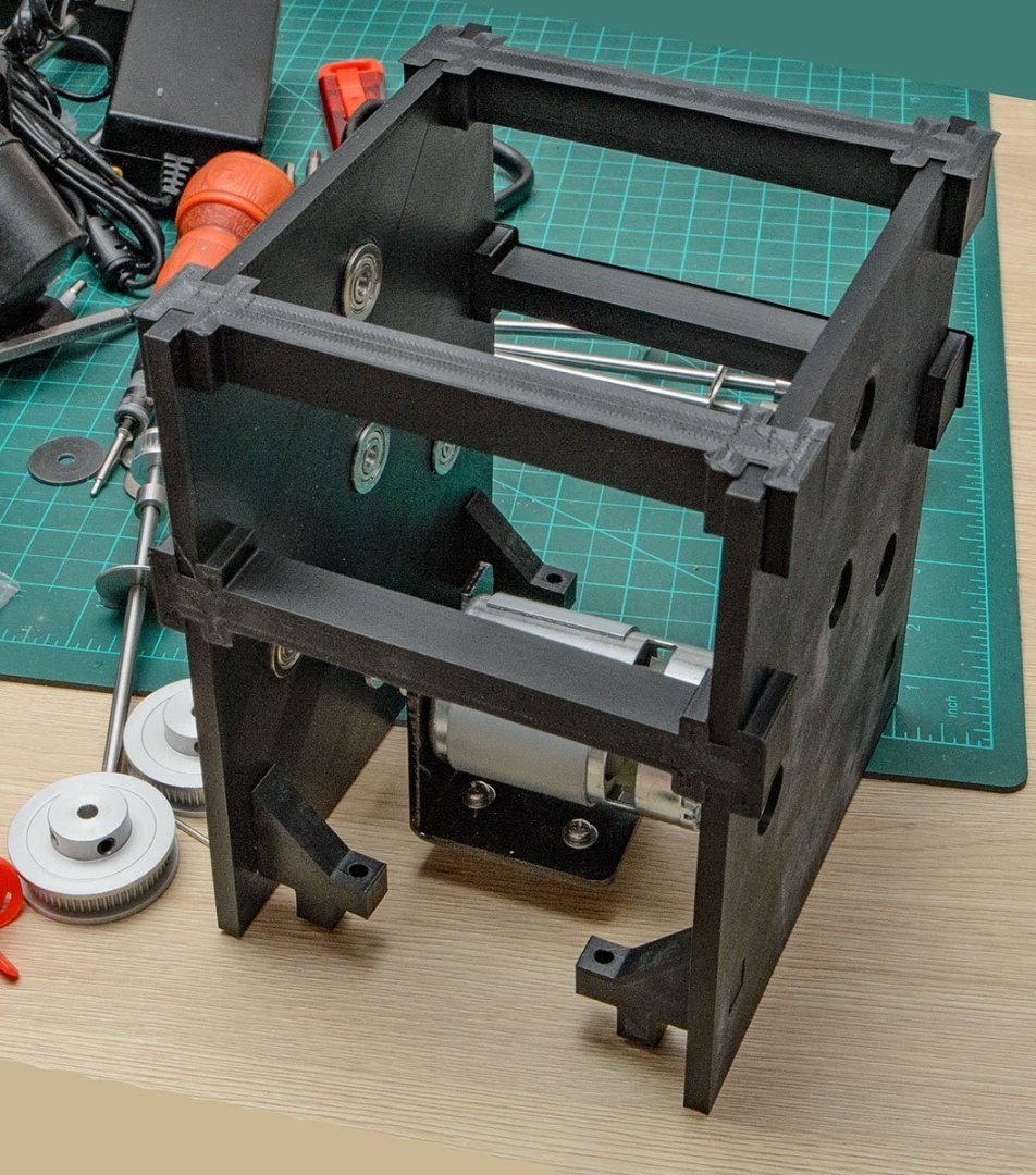
I replaced all the noisy mechanicals with electric motors. The test result is remarkable, and I'm printing a new housing. This 1 meter long sliding rail will hold the housing. The price is about $30.
-
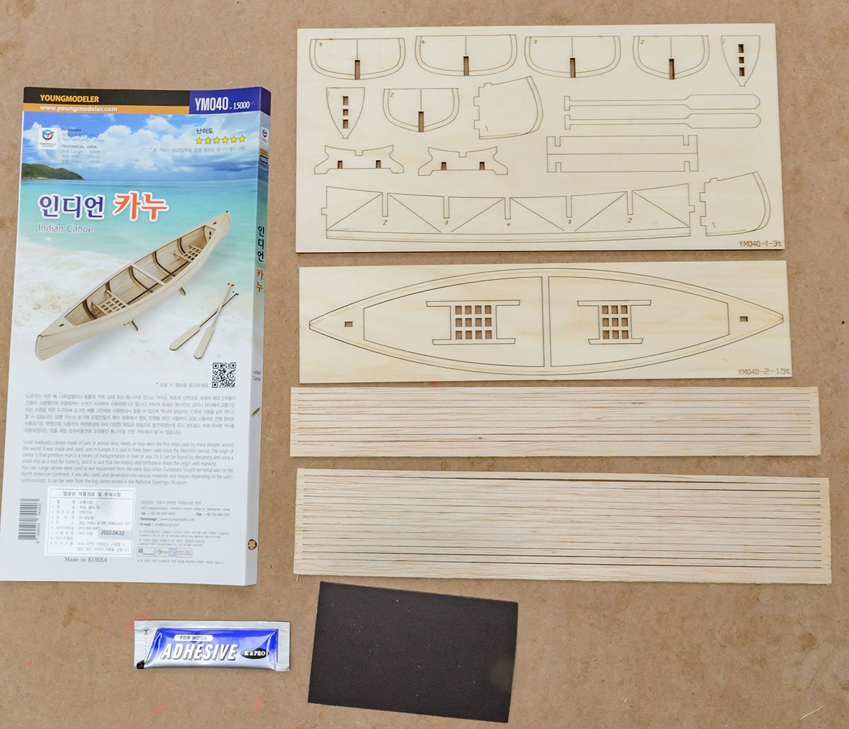
The Young Modeler is a wooden kit manufacturer in South Korea. Consider it a domestic company in each country. https://www.scalemates.com/kits/youngmodeler-ym005-ga-geo-korean-ship--1429935 Unfortunately, most kits are toys for children. There aren't many kits in terms of historical or realistic models. It is good to go to traditional Western company kits unless you want Han-seon (traditional Korean ships) kits.
-
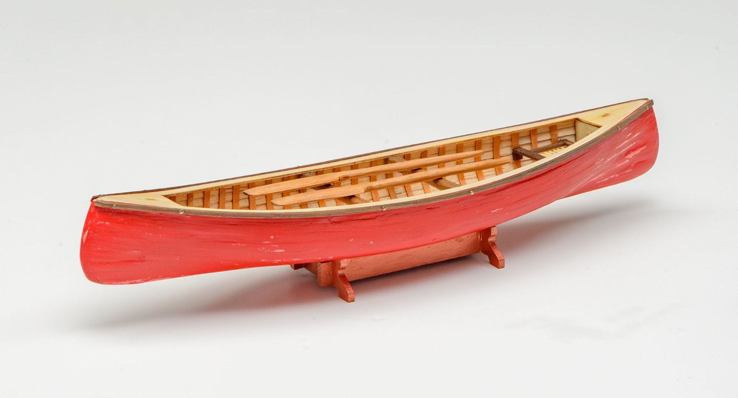
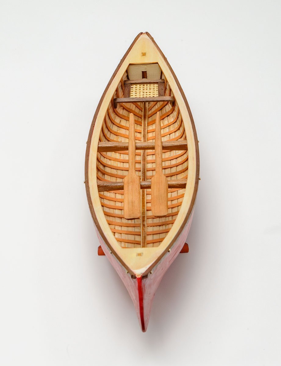
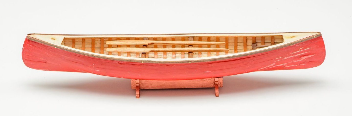
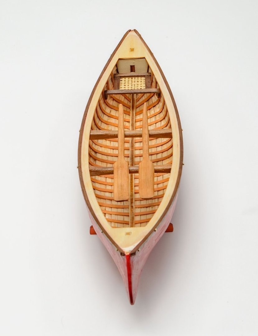
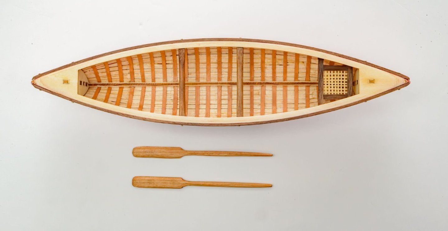
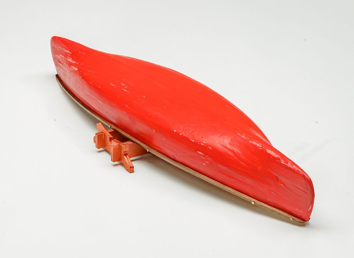
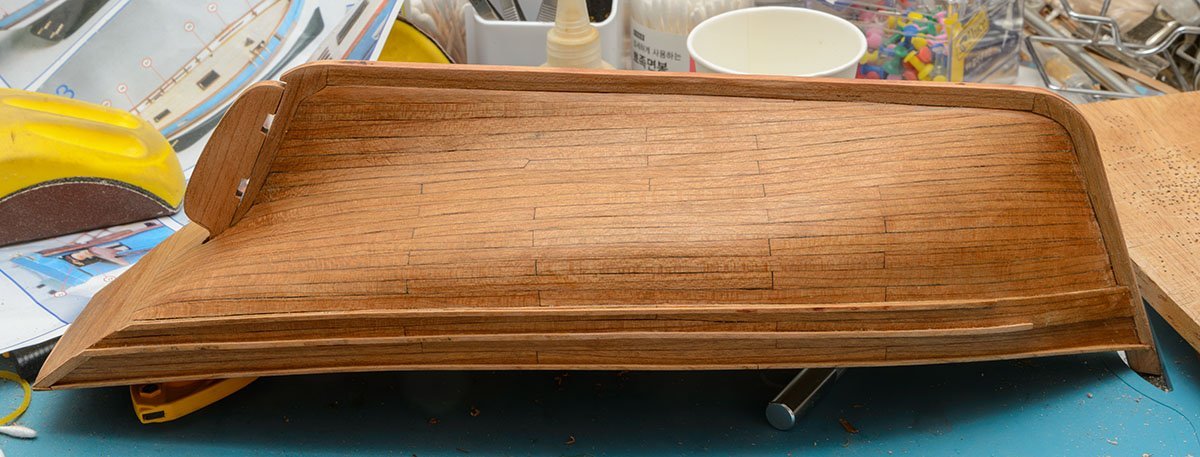
This is a $7 easy toy kit. I added details based on the American Chestnut Canoe. Happy new year~

-
I completed it, but the machine has serious issues. I can control the motor speed and direction, but it became louder than Rope Rocket with a hand drill. I think too many drivers cause the noise and high friction. Also, the wider distance between the hooks makes rope-making difficult. I have to redesign the entire machine and buy more parts...
-
Thanks for your help, Chuck. Your video explained well how to run the RR. I'll post the model file once I complete and verify the MRR.
-
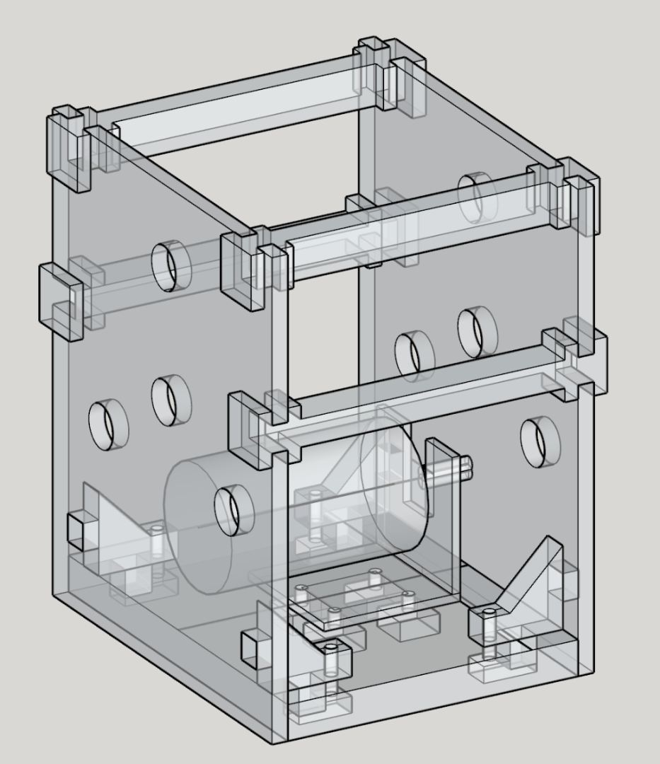
I learned that the Syren Rope Rocket is much simpler and more universal than the Domanoff's PL4 machine. A true evaluation. However, I need to fix some drawbacks of the RR. (1) Motors aren't integrated into the machine. I have to hold a heavy drill when I run it. (2) The gears are extremely loud. It is also the worst flaw of the Domanoff's. I replaced the drill with a 775 RC motor with speed control. Also, the gears are replaced with a timing belt. Because I'm a lazy person, I'm printing all the parts with a 3D printer. The 3D printer is printing the last part, which will be done in 11 hours. 😴 Question: Can I open the blue print of the new machine in public? I copied the structure from the Syren Rope Rocket. I checked for any patents issue, and found no related descriptions. I would like to be sure that sharing my work is legitimate.
-
This is a really awesome and brilliant method, Ainars. I'll try the same jig with a 3D FDM printer.
- 12 replies
-
- 1
-
-
- Armed Longboat
- Ancre
- (and 1 more)
-
I'll go on vacation and plan my annual schedule for modeling. I hope you enjoyed my build log, and Happy New Year!


- 17 replies
-
- 6
-
-

-
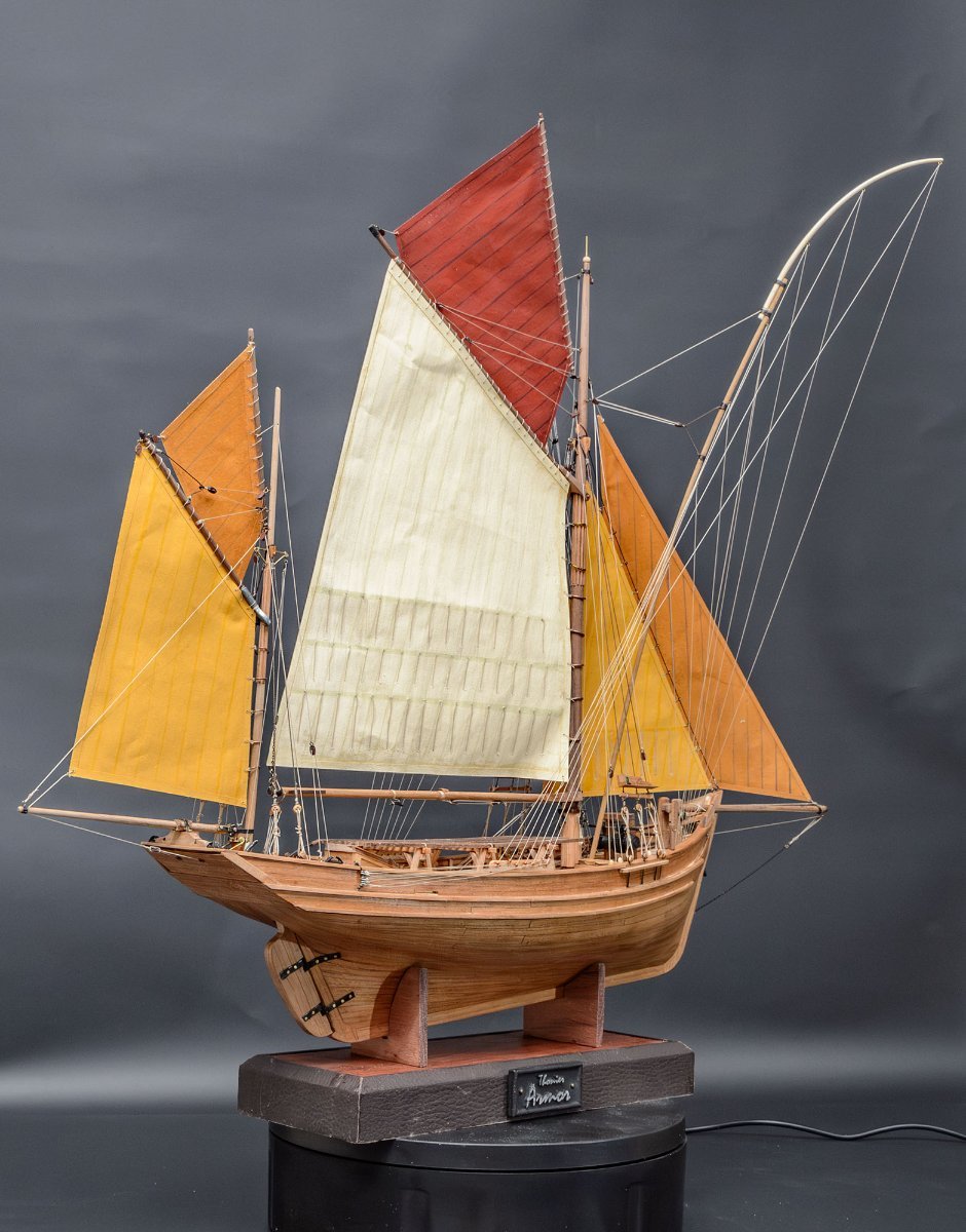
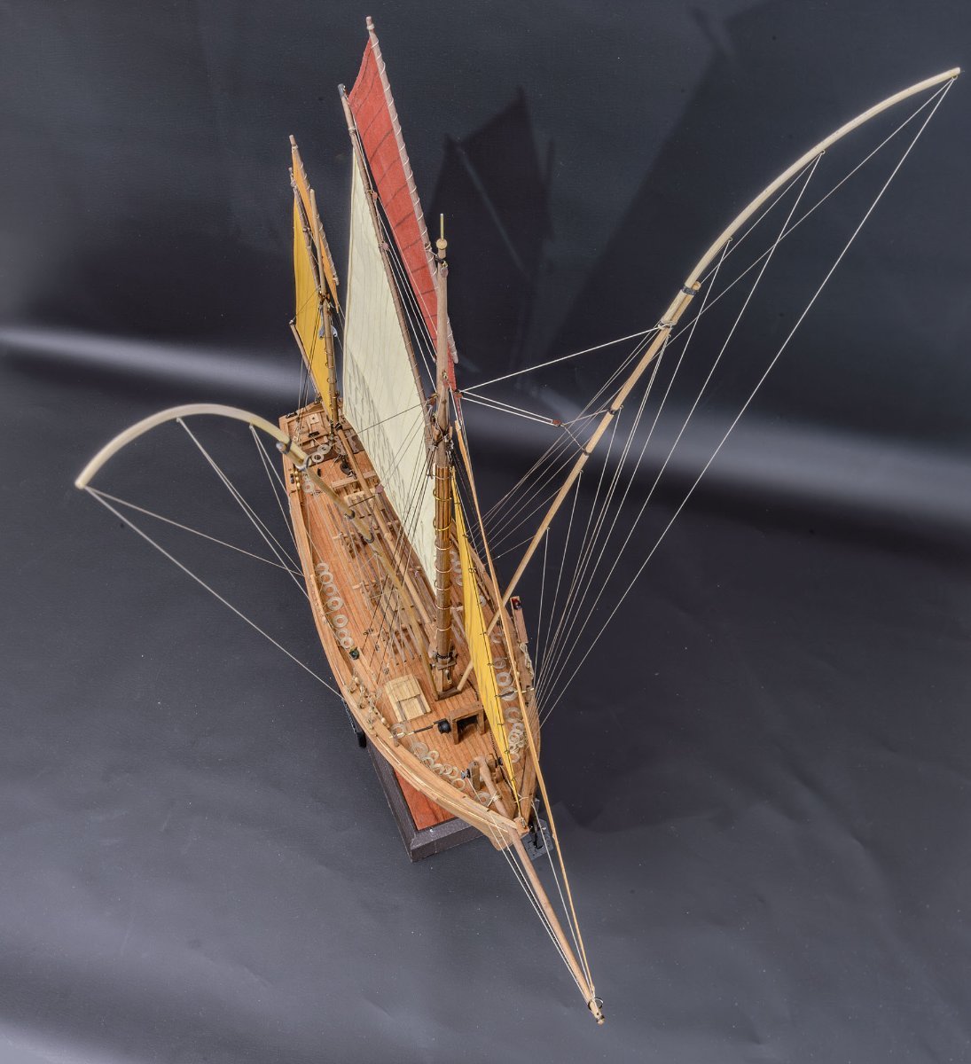
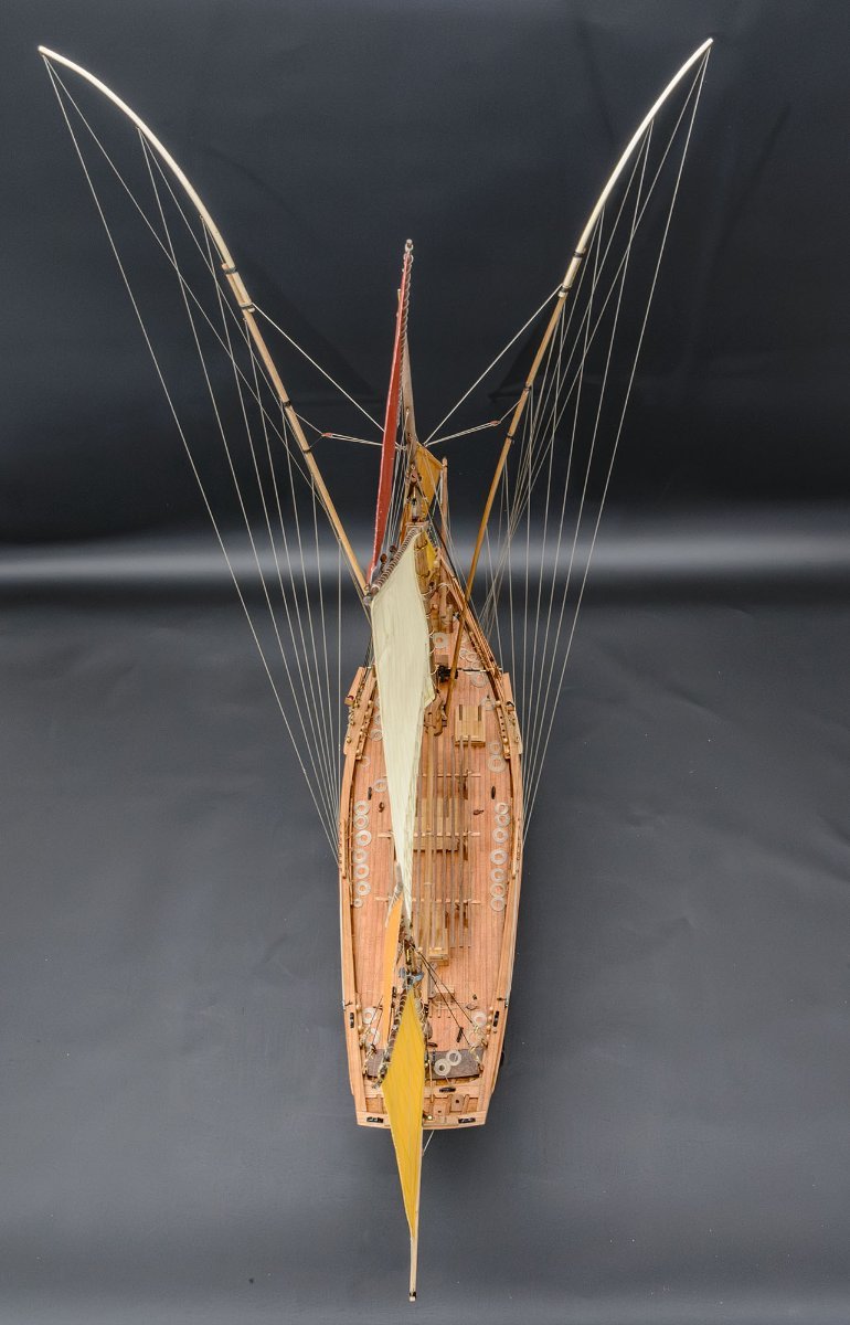
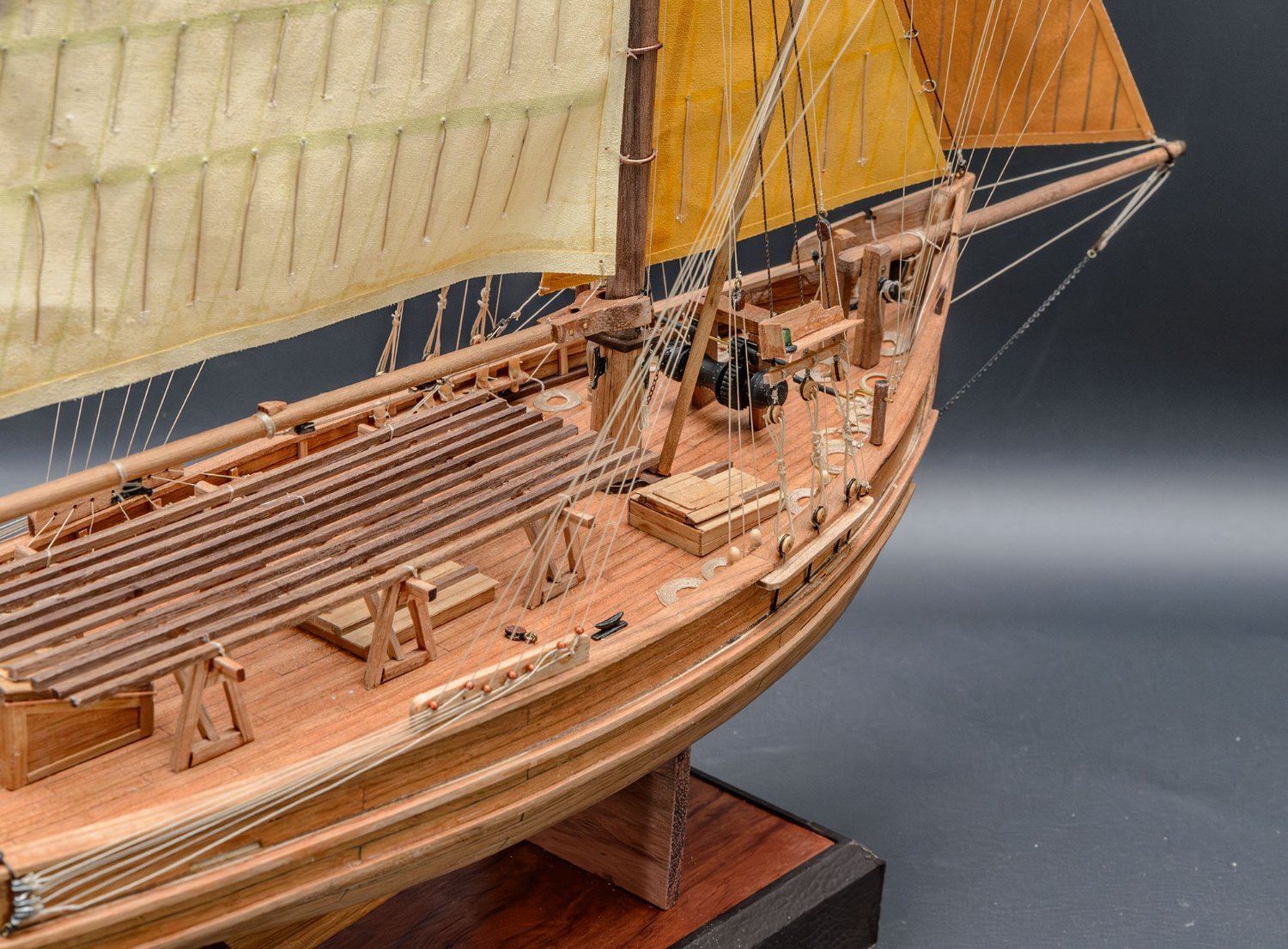
- Marie-Jeanne
- Artesania Latina
- (and 1 more)
-
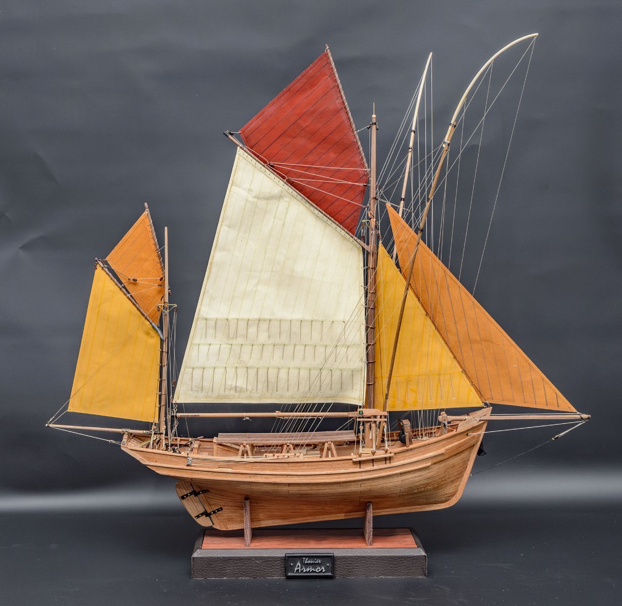
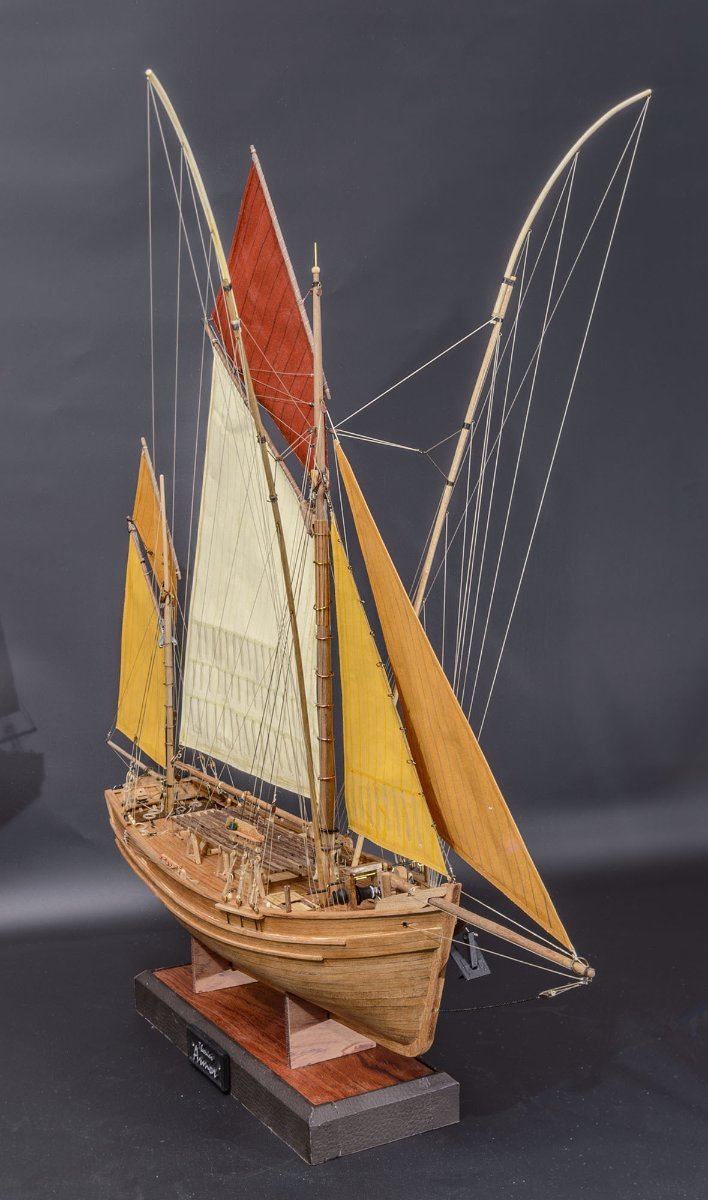
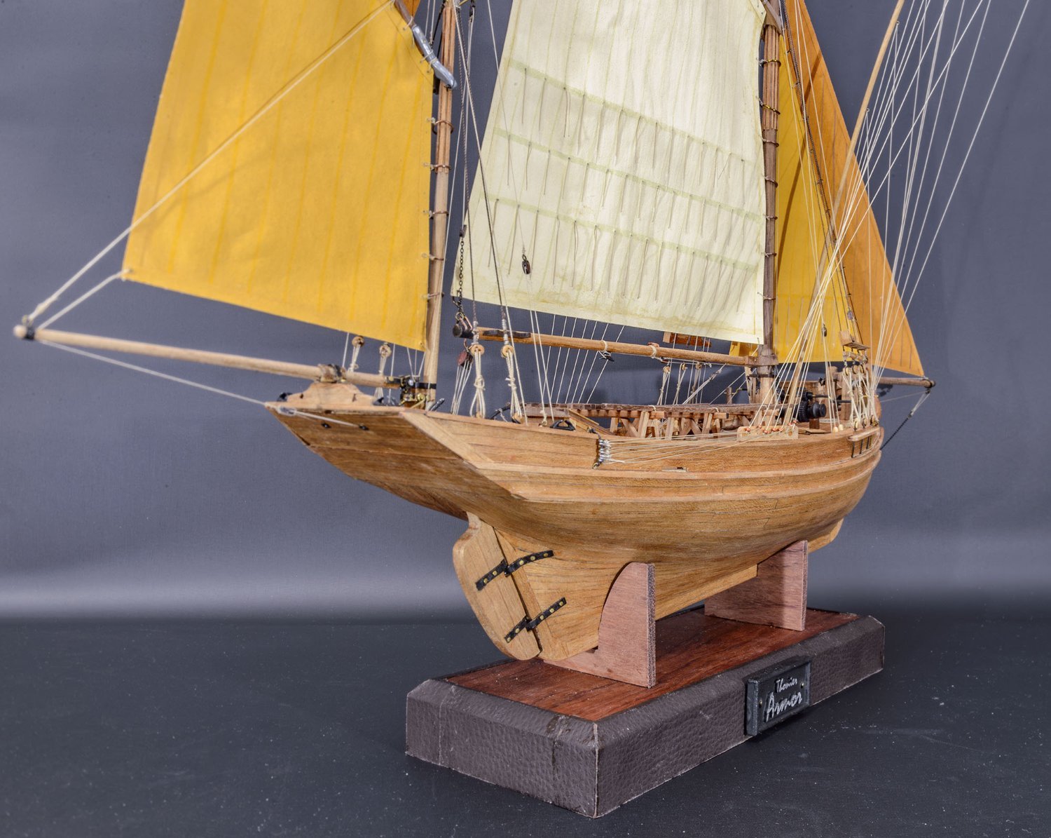
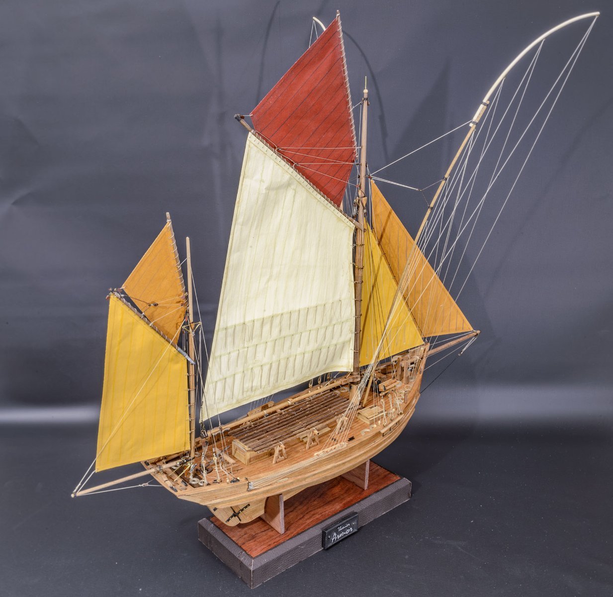
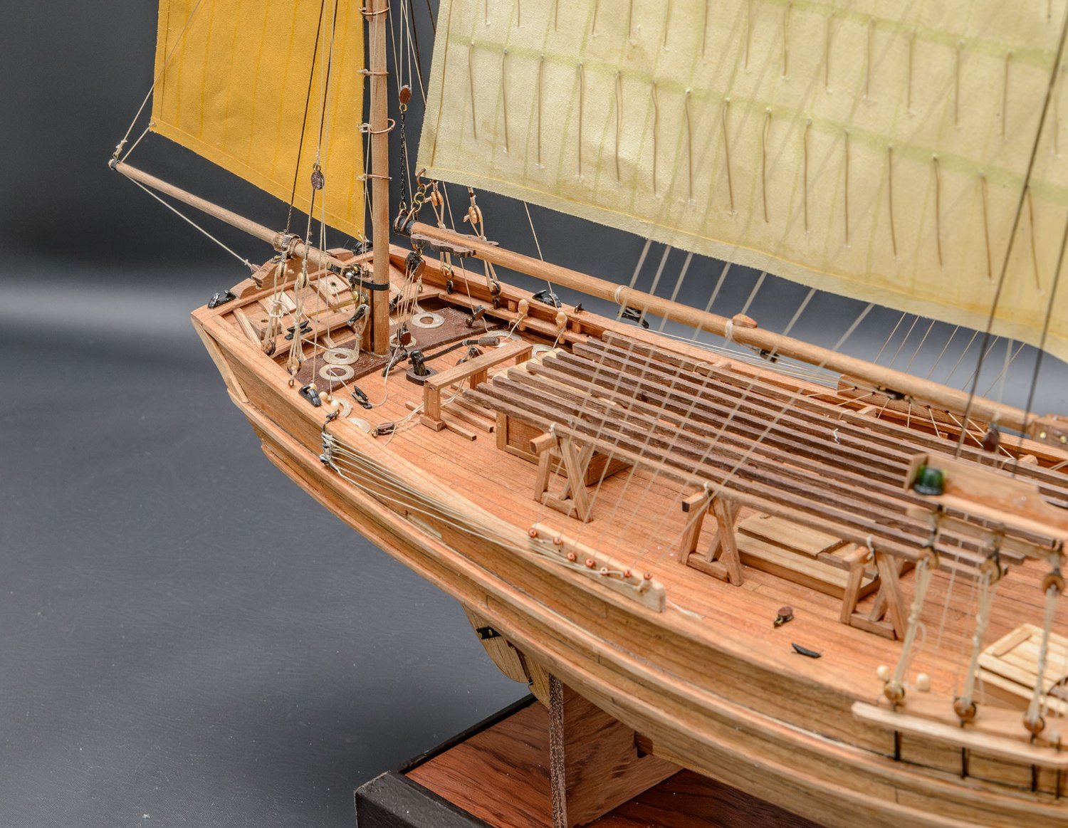
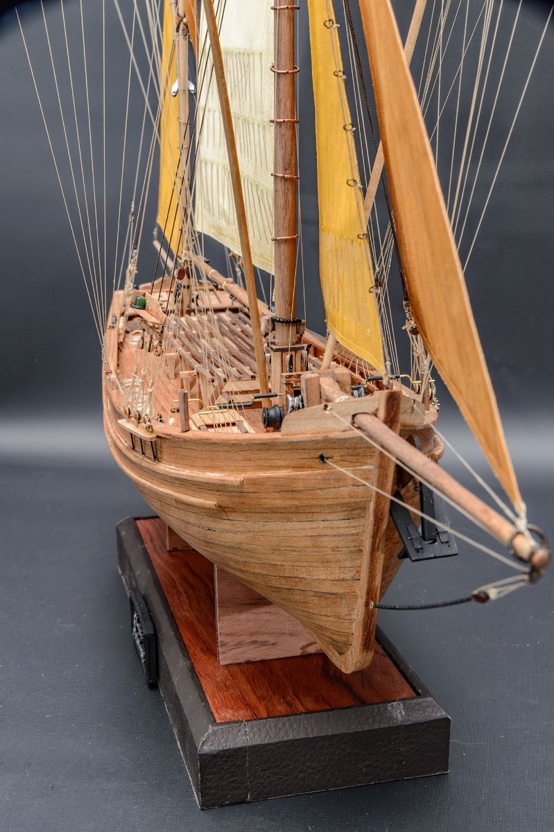
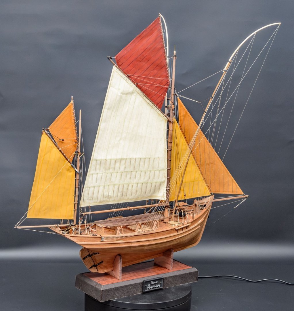
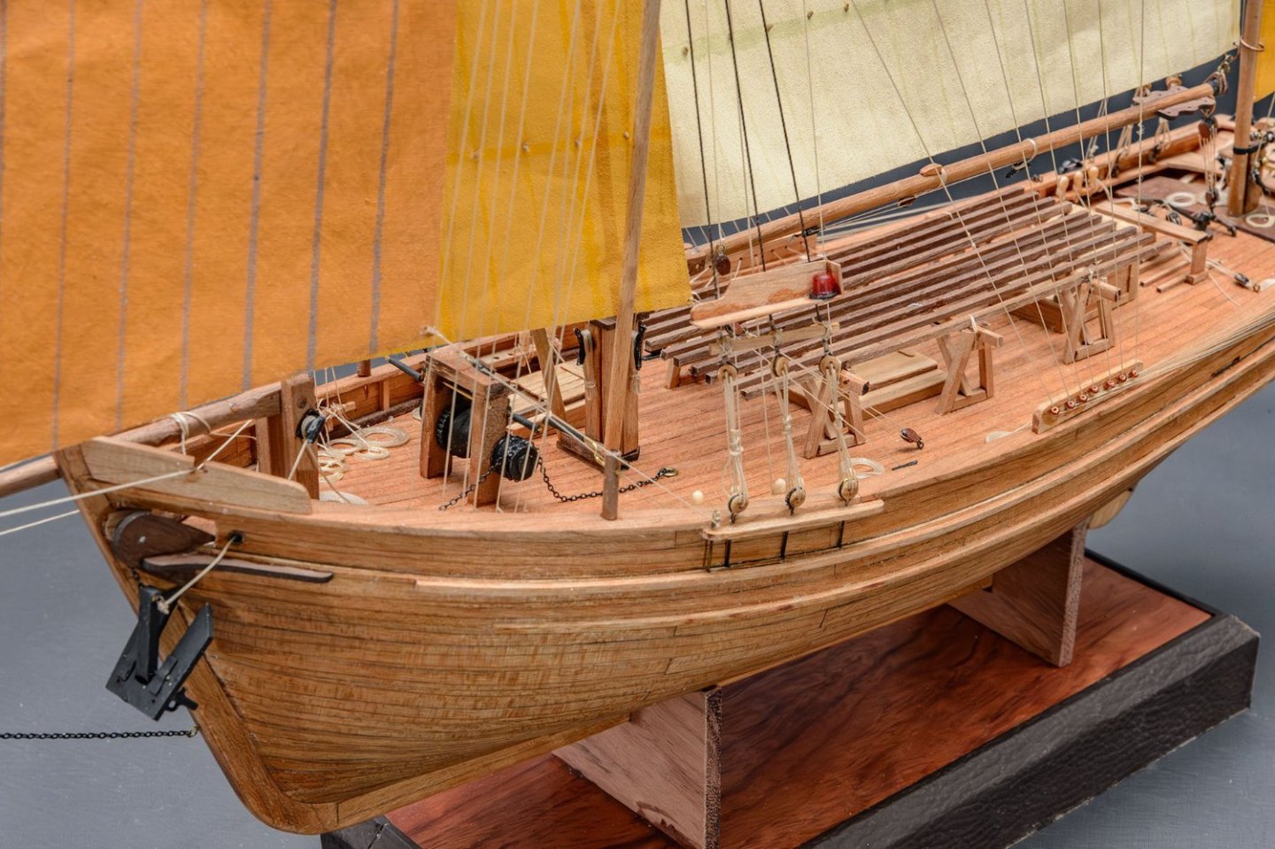
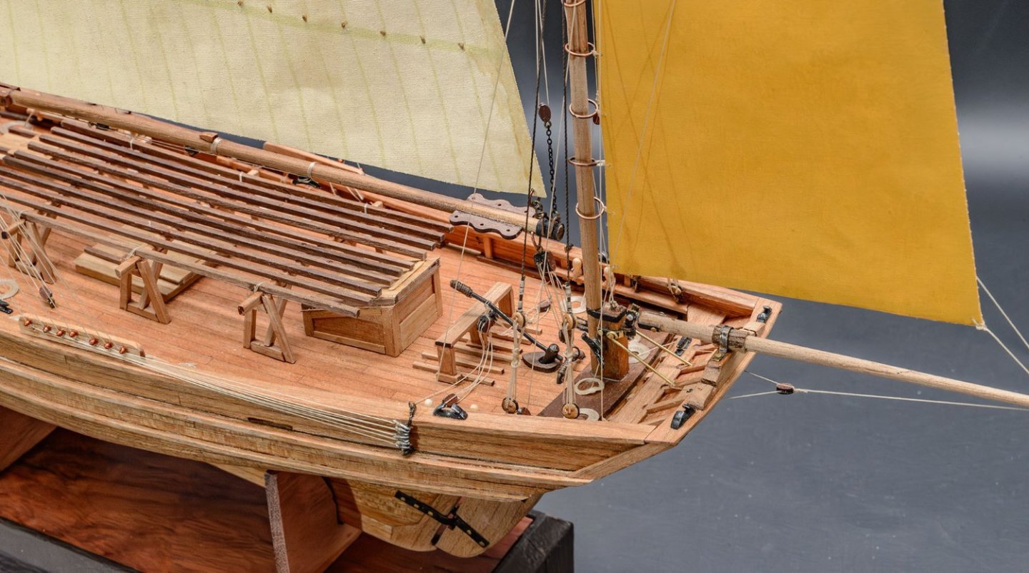
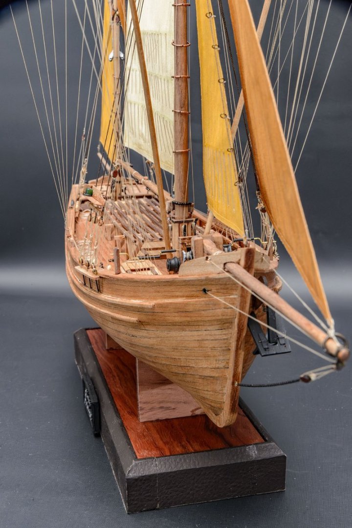
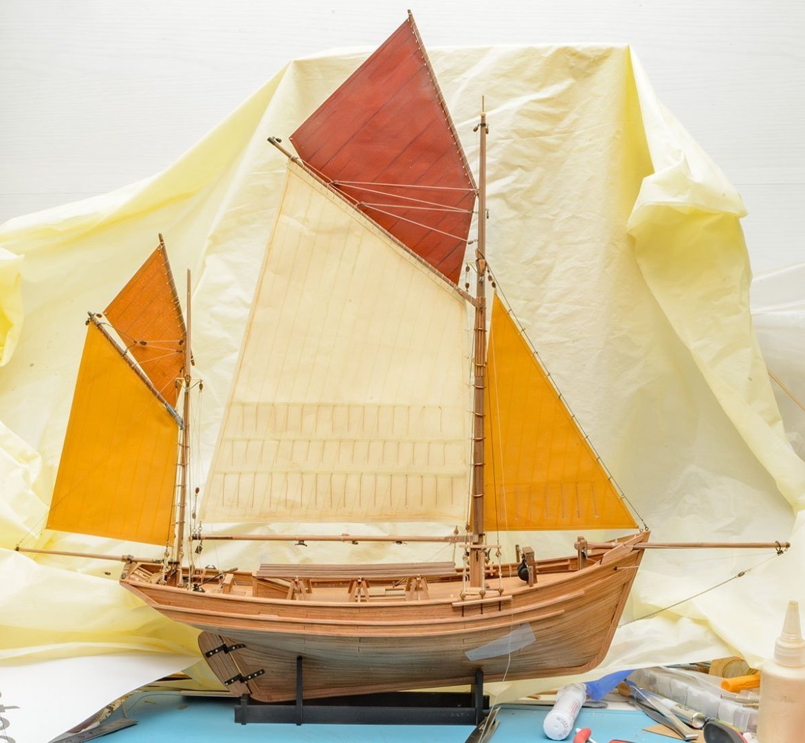
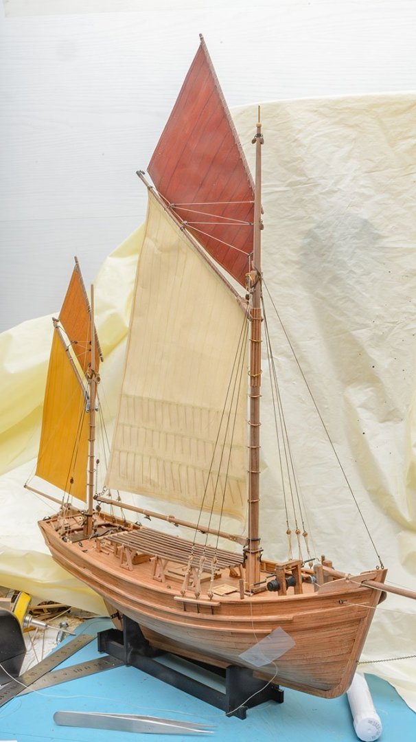
OK, let's wrap up my build log. These are some tips I used. Printed templates The stock metal parts are made of steel, which is much difficult than brass or tin metal. After I broke several drill bits, I copied the parts using 3D resin printer. Also, the stock anchor wasn't good. I made an anchor, which the real thonier ships use. I simply painted sail battens. It is very easy to produce rope hanks. I mass-produced the hanks and applied them.

- 17 replies
-
- 2
-
-
- Marie-Jeanne
- Artesania Latina
- (and 1 more)
-
I couldn't finish it this year (last year in Korea). It's time to see the new year's sun. I send you best wishes for the New Year~
- 17 replies
-
- 3
-
-
-
- Marie-Jeanne
- Artesania Latina
- (and 1 more)
-
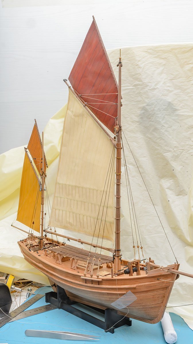
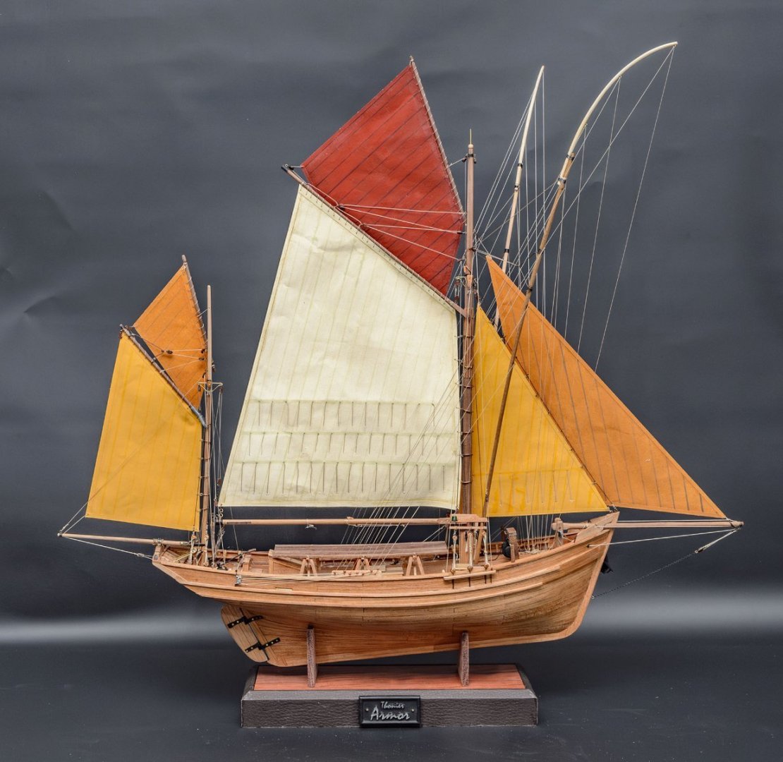
I finished yards. The last parts are sails-the most difficult one. 😎
- 17 replies
-
- 2
-
-
-
- Marie-Jeanne
- Artesania Latina
- (and 1 more)
-
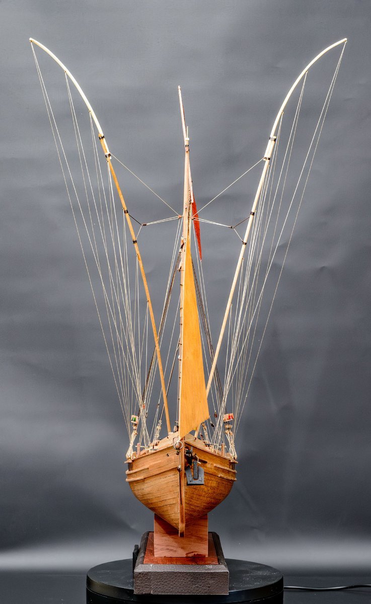
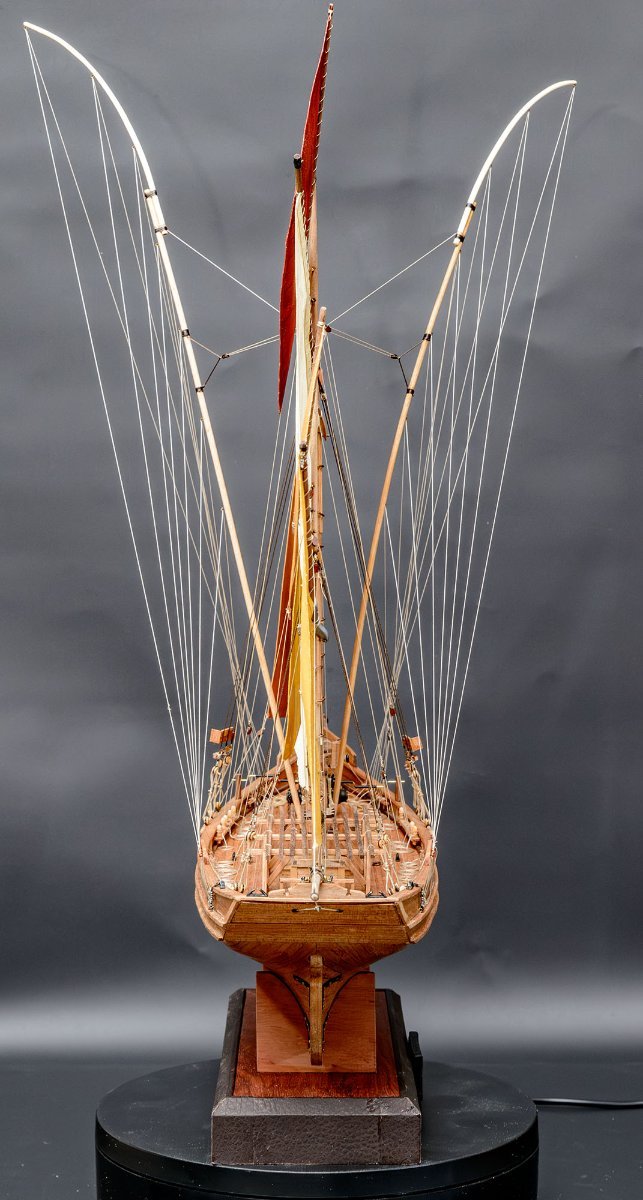
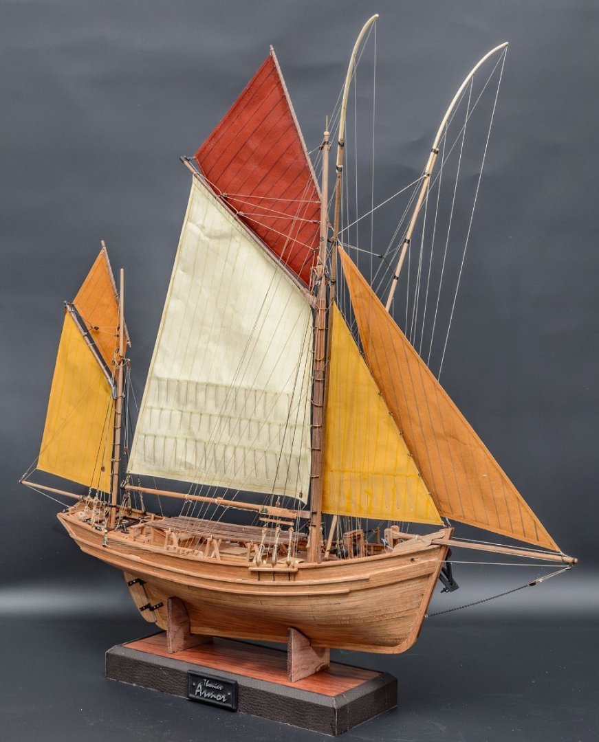
I finished standing rigging. Can I finish it this year?

- 17 replies
-
- 6
-
-
-
- Marie-Jeanne
- Artesania Latina
- (and 1 more)
-
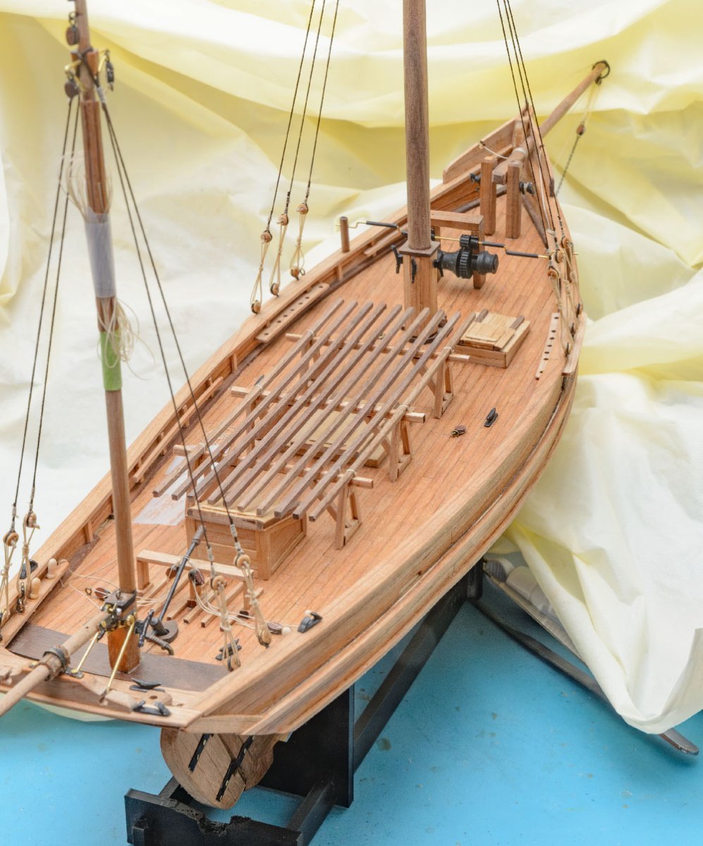
The kit's winch parts were hard to handle. The tin parts have no holes. After I failed to drill some wheels, I copied the wheels using a 3D printer. Another daily task was finishing the bottom of the mizzen mast.
- 17 replies
-
- 5
-
-
- Marie-Jeanne
- Artesania Latina
- (and 1 more)
-
I'm rushing and running. I really hope to finish standing rigging before Christmas.
- 17 replies
-
- 4
-
-
- Marie-Jeanne
- Artesania Latina
- (and 1 more)
-
Congratulation! Very nice painting and educational build log. I bought the same kit and will try again next year. Merry christmas and happy new year~
- 38 replies
-
- 1
-
-
- Model Shipways
- Shipwright Series
- (and 2 more)
-
Thanks for your comment, Yves. I'm sorry about the long vacation. I have experienced long hiccups while dancing on inaccurate references. Due to my high expectations, I referred to some internet manuals from Billing boats (BB580) and AL (22175 newer kit). Also, I checked videos of the real thonier on Youtube. They were confusing because they had only a fewer intersections. I was struggling between the three manuals and videos to build the best thonier. I finally found the most reliable source, such as the AAMM monograph. * More reliable reference list https://boutique.aamm.fr/plan-thonier-marie-jeanne https://planeteloisirs-bg.fr/index_fichiers/pages/bateau/marie-jeanne-1.html https://www.amazon.com/dp/2213003858 If you want to build a better thonier than any consumer kit, I recommend buying the AAMM monograph. Unfortunately, it is too late to buy the book because I want to wrap up this project this year. 😂
- 17 replies
-
- 3
-
-
- Marie-Jeanne
- Artesania Latina
- (and 1 more)