modeller_masa
-
Posts
950 -
Joined
-
Last visited
Content Type
Profiles
Forums
Gallery
Events
Everything posted by modeller_masa
-
https://www.gettyimages.com/detail/news-photo/diver-investigates-the-shipwreck-of-french-navys-society-at-news-photo/1495948834 The ship with scuba diver is a different ship. Yeah. It's the media.
-
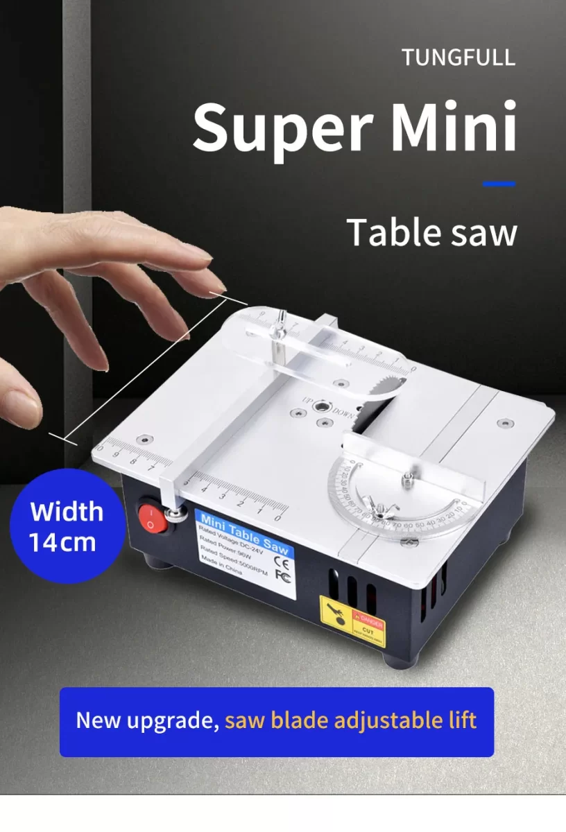
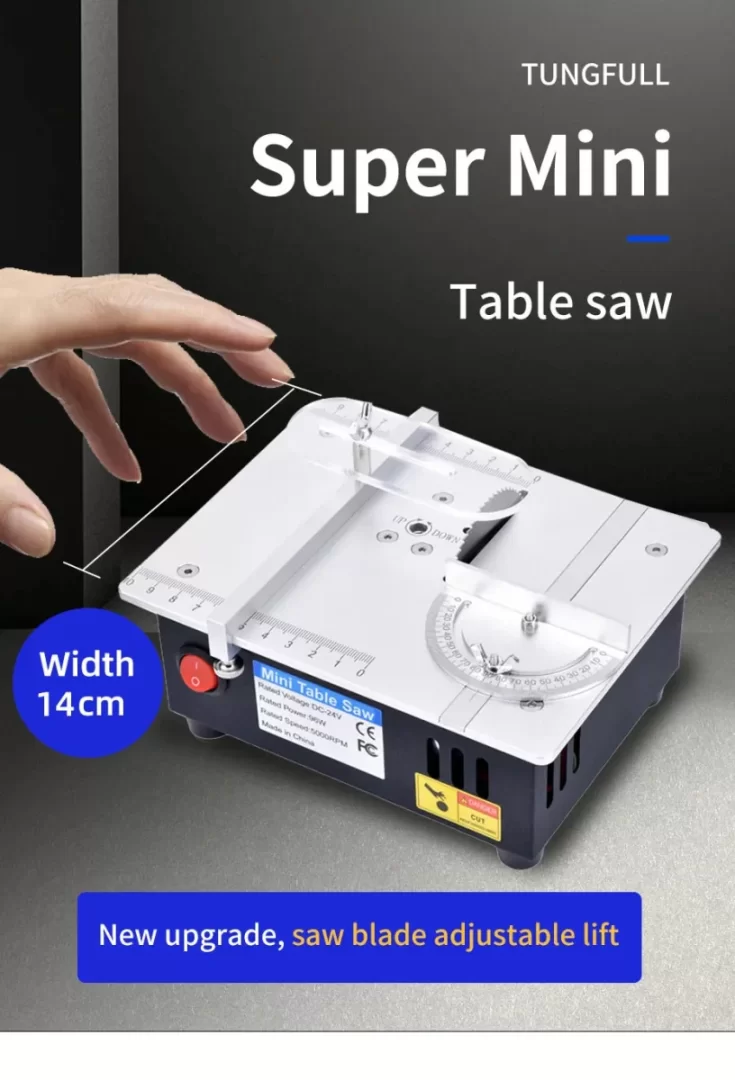
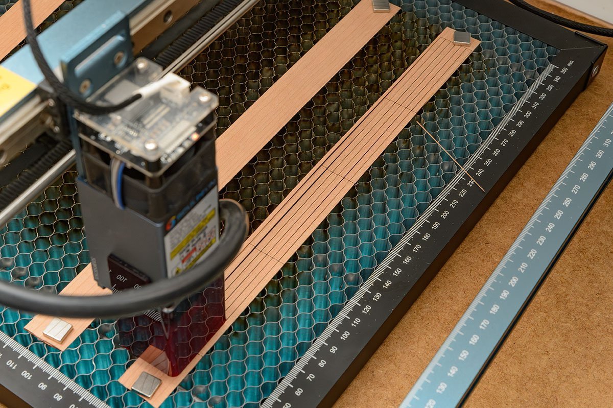
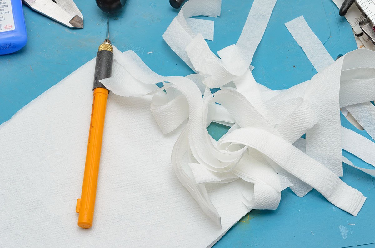
The saw is as light as the KS230, and it doesn't have desktop clamp. Also, the dust collector is useless. I'm so afraid of any kind of table saw, so I prefer to use a laser cutter. (extension plate)
-
I think the motor is 775. Not quite different from the KS230. The low power motor is dangerous when I cut hard wood. Good replacement for the KS230, but it is incomparable to Byrnes.
-
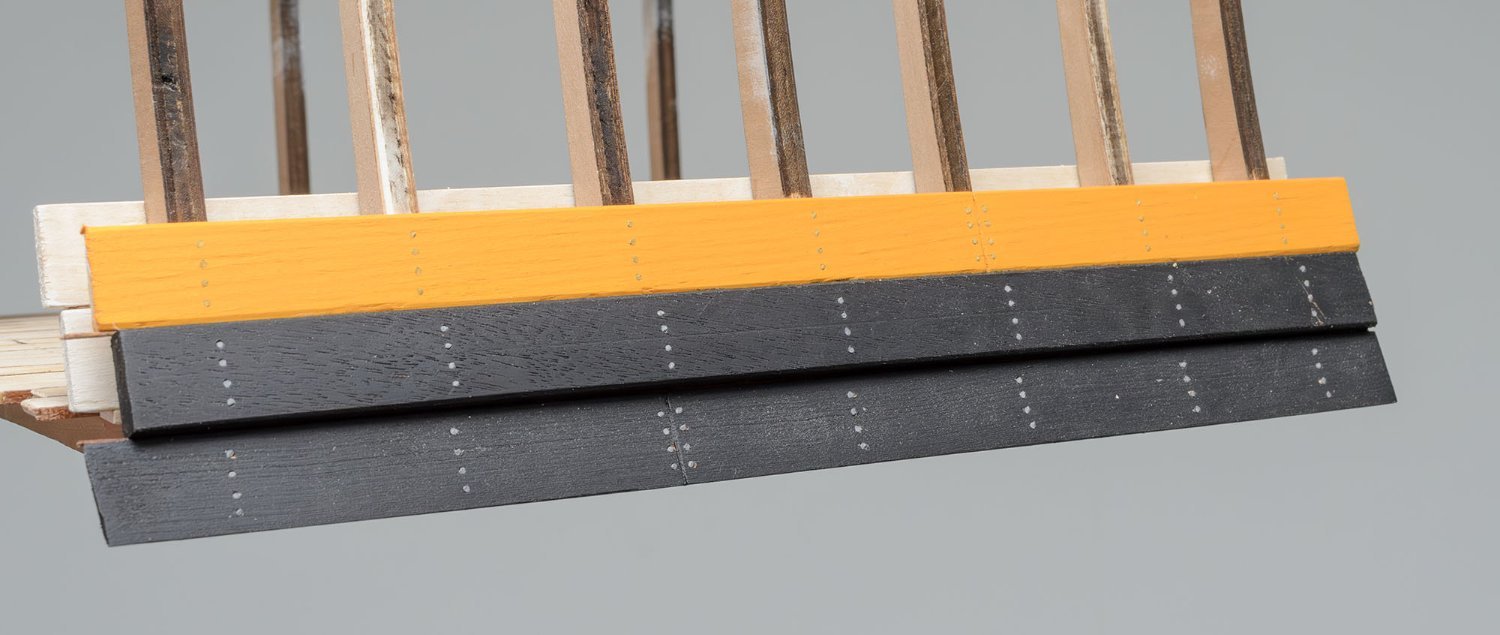
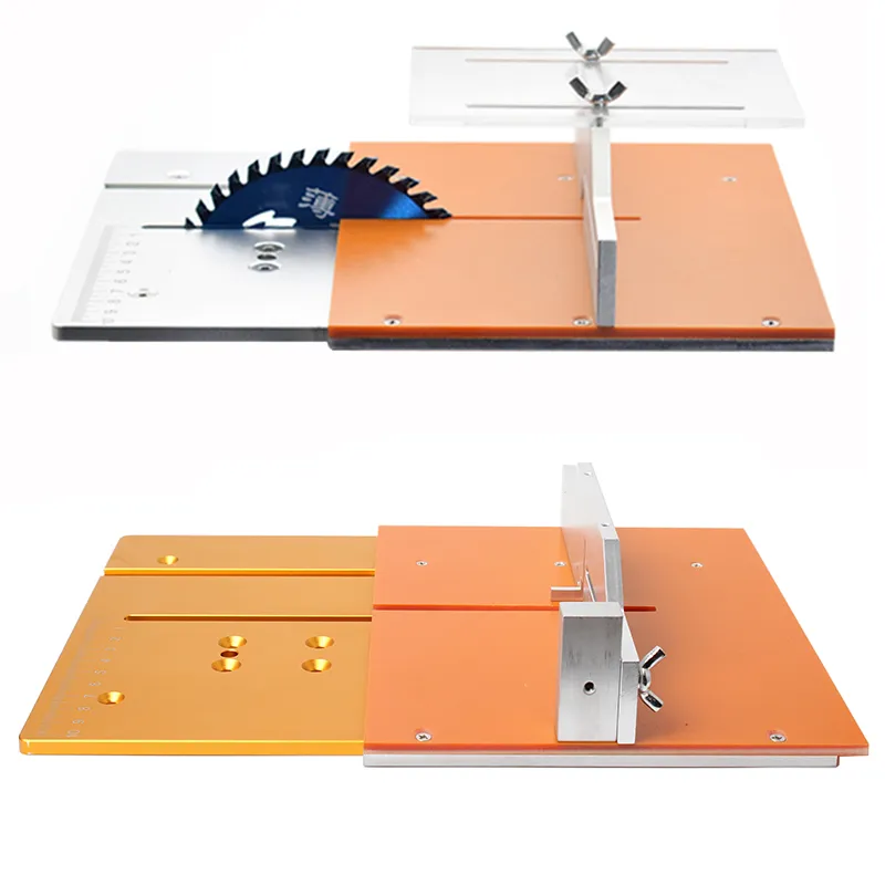
I bought a Chinese mini table saw that addressed all the things - height adjustment, replaceable plate with sturdy fence and zero insert, and bigger 3 inch blade - for $40. The only drawback is safety. 😂 By the way, I'll order a full set of the Byrnes table saw when they re-open. I'm worry about the end of their family business...
-
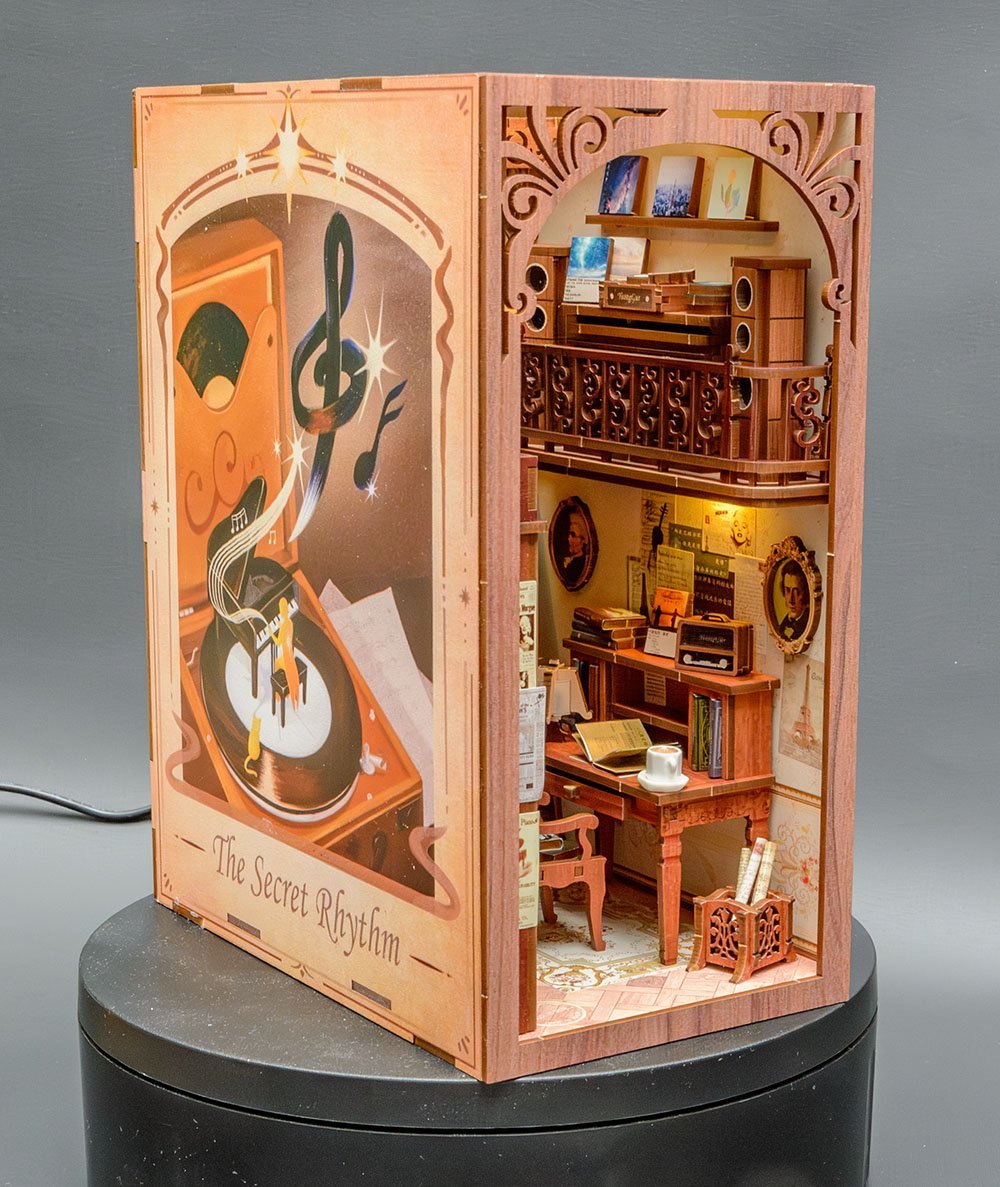
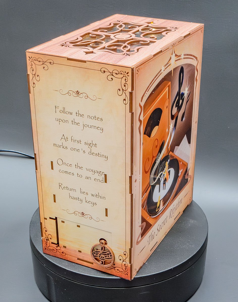
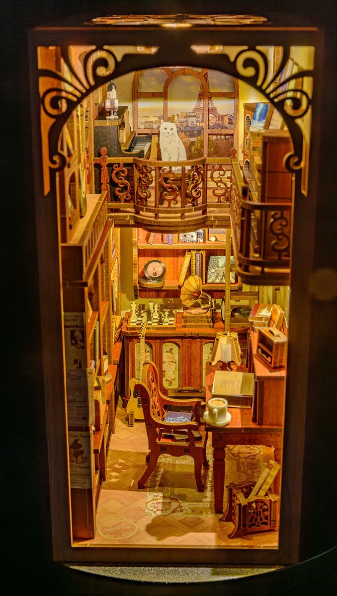
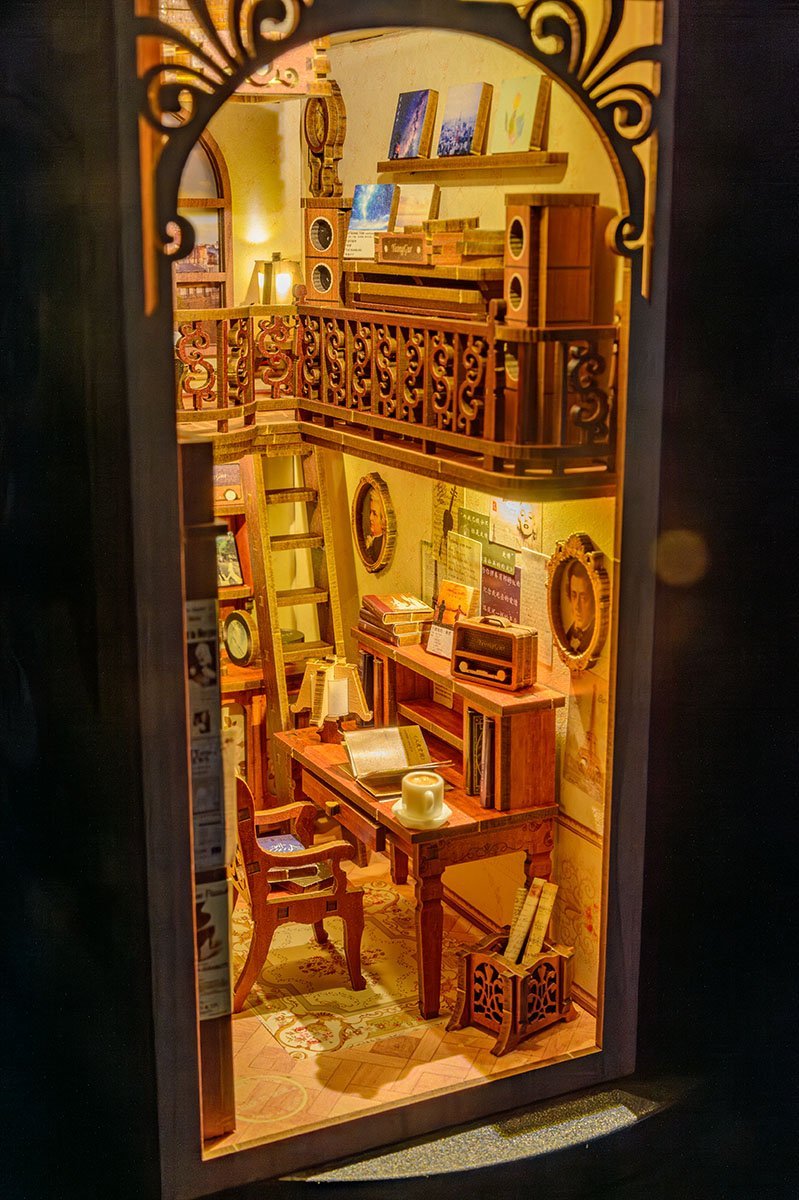
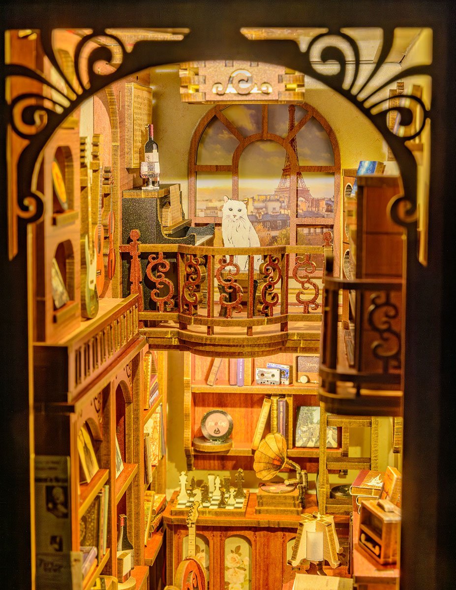
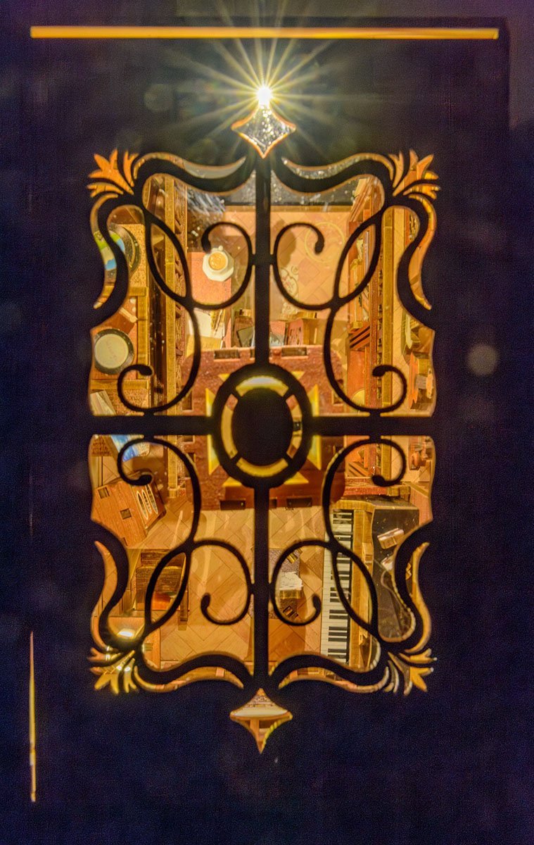
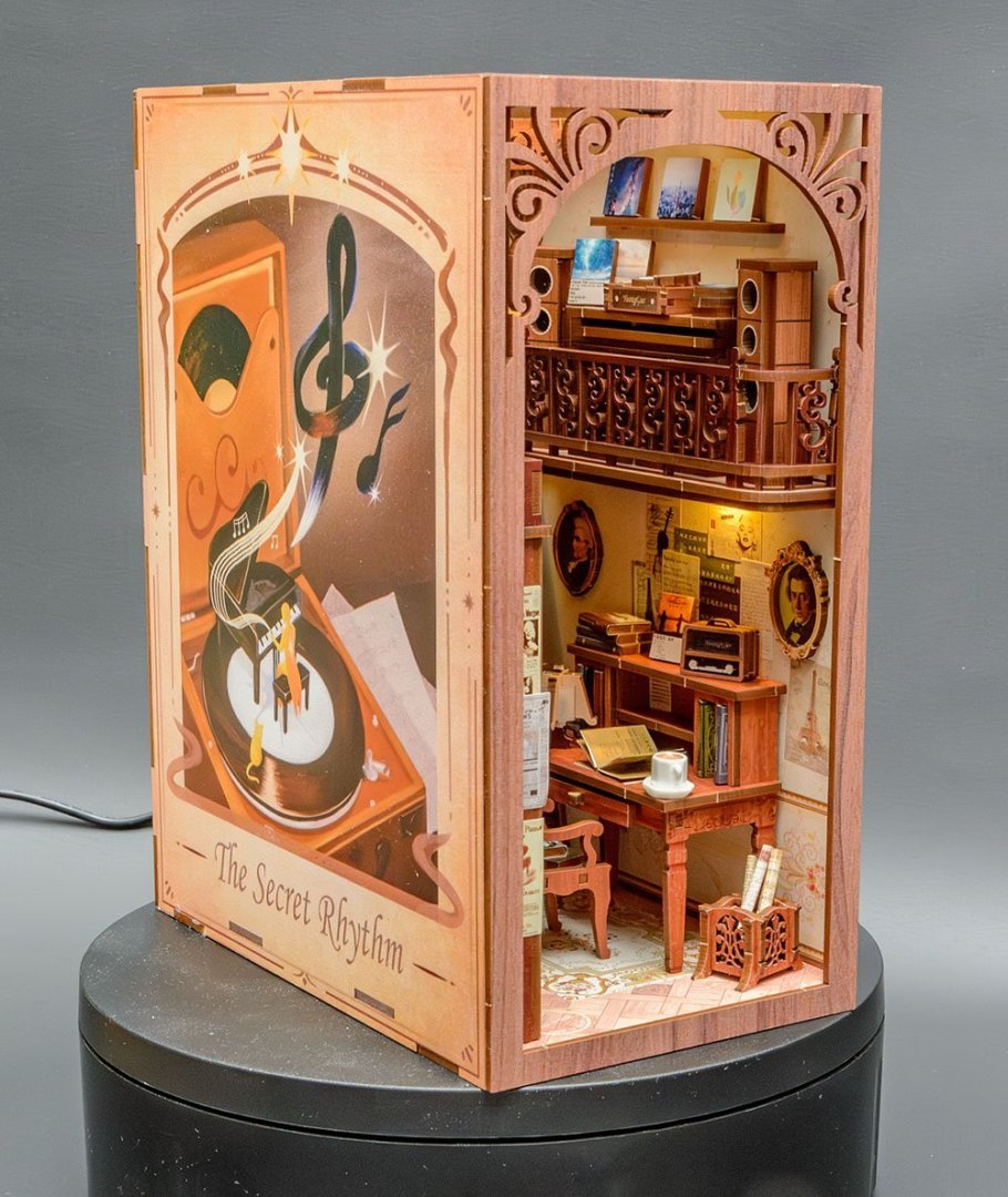
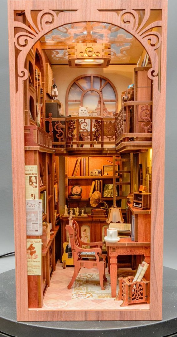
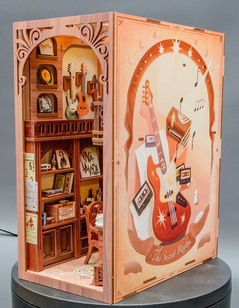
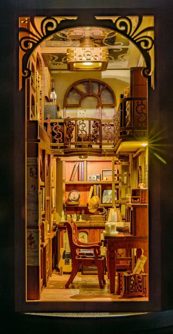
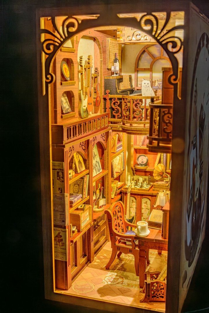
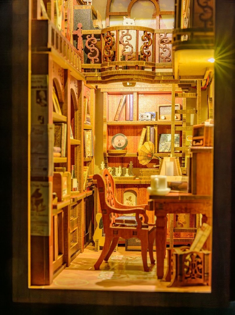
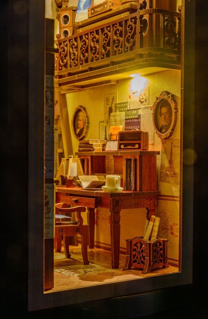
This kit is less complicated than than my previous Book Nook projects from Robotime. Kits from CuteBee will be good presents for elementary school kids. 😎


- 1 reply
-
- 10
-

-

-
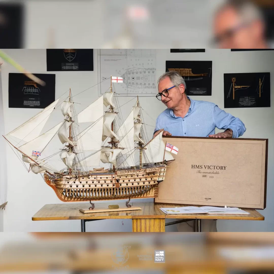
OcCre HMS Victory Limited edition
modeller_masa replied to modeller_masa's topic in Wood ship model kits
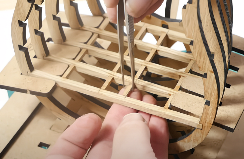
I cancel my opinion about the difficulty level. I thought that the kit designers might use smart joints for hull framing. Unfortunately not. The build-log video shows the kit didn't prepare pre-cut beams, which may cause significantly distorted hull fairing, especially when beginners build. 🤔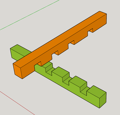
-
OcCre HMS Victory Limited edition
modeller_masa replied to modeller_masa's topic in Wood ship model kits
Due to the simplified hull, it looks like the easiest HMS Victory kit under 1/90 scale in my opinion. Hull fairing and planking are really big hurdle for beginners. I'm glad more companies release new kits. -
One interesting trend is that the banned manufactures are copying and reselling the products from the legit companies in Chinese market. 🤔
-
https://occre.com/en/pages/hms-victory The newest HMS Victory kit has arrived. - 1/87 - 1,172 mm long - 999 Limited produciton - 1,400 EUR = 1,501 USD
-
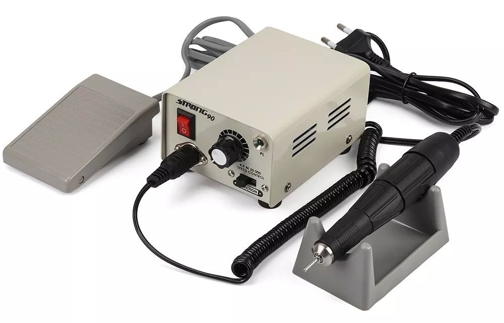
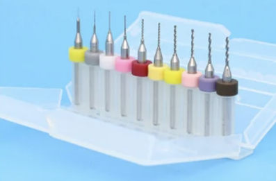
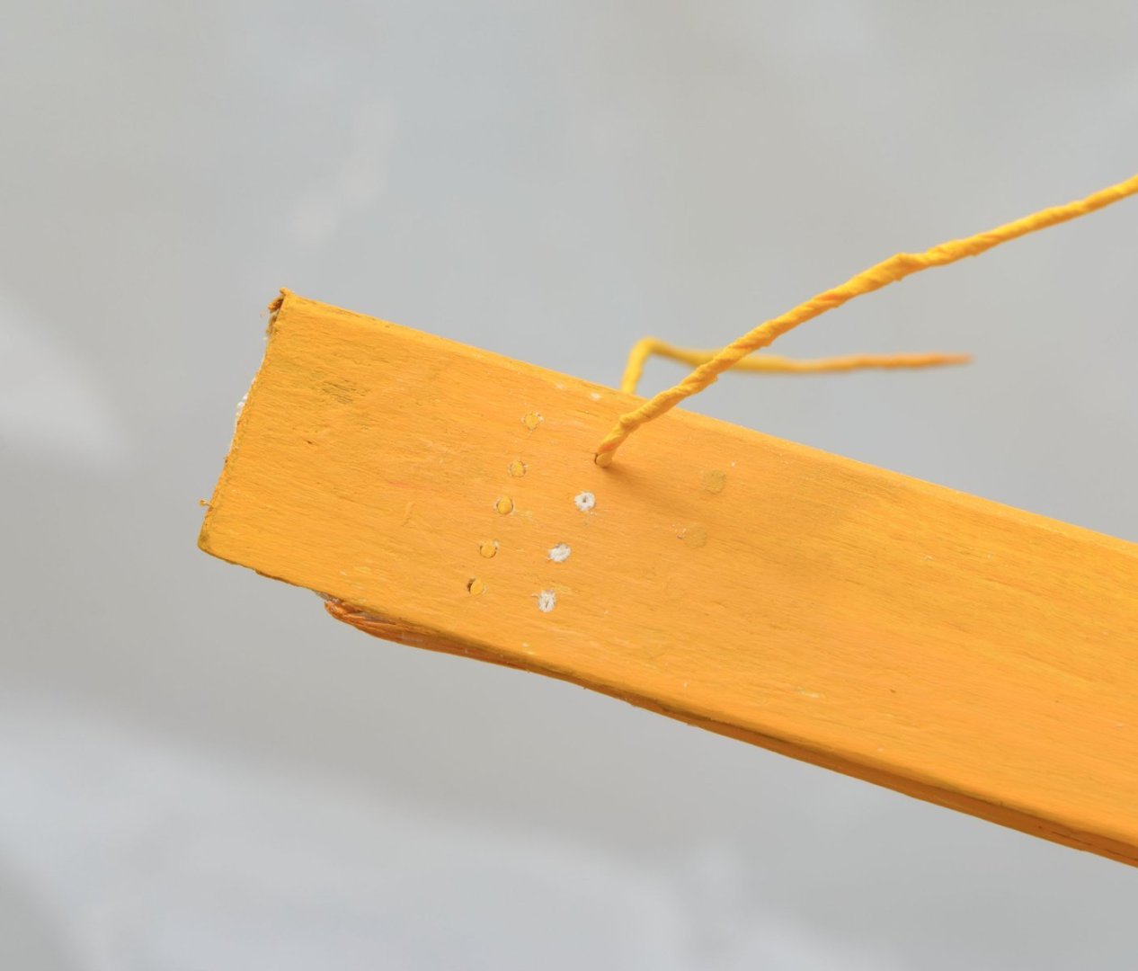
I'm using $50 handpiece. - Strong 90 drill station with pedal - Strong 102L handpiece : Replaceable drill chuck - 2.35mm, 3.00mm, 3.15mm This is my favorite PCB drill bit. The price is $1~1.50 per 10 pcs. Size varies from 0.10mm to 3.15mm by 0.05mm. I bought all the variations.
-
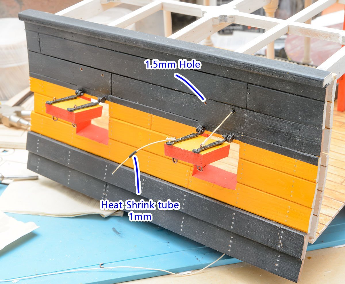
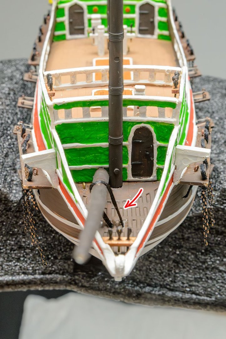
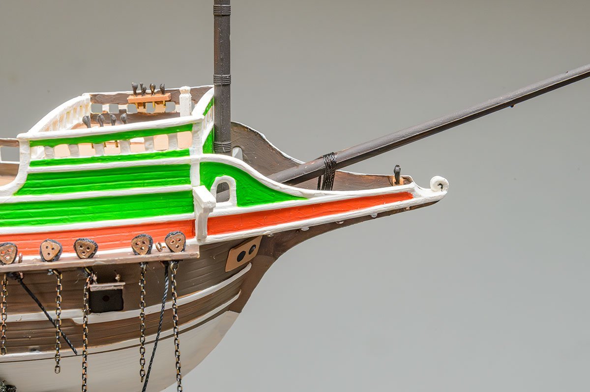
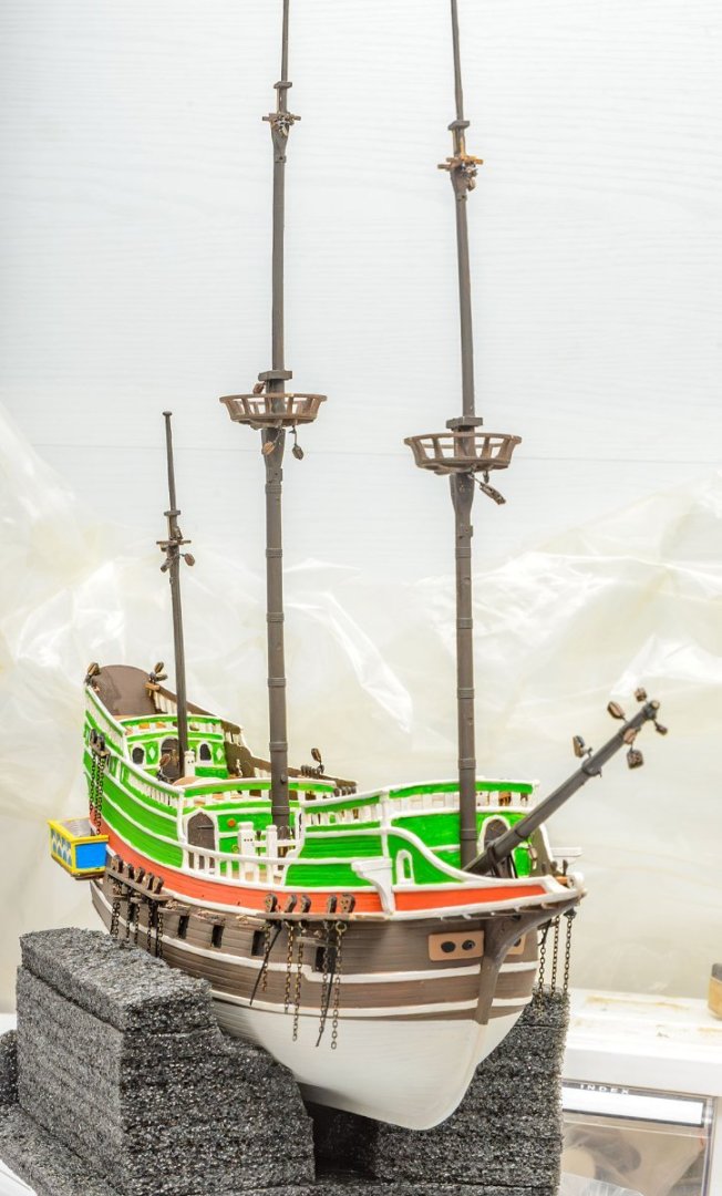
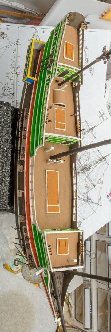
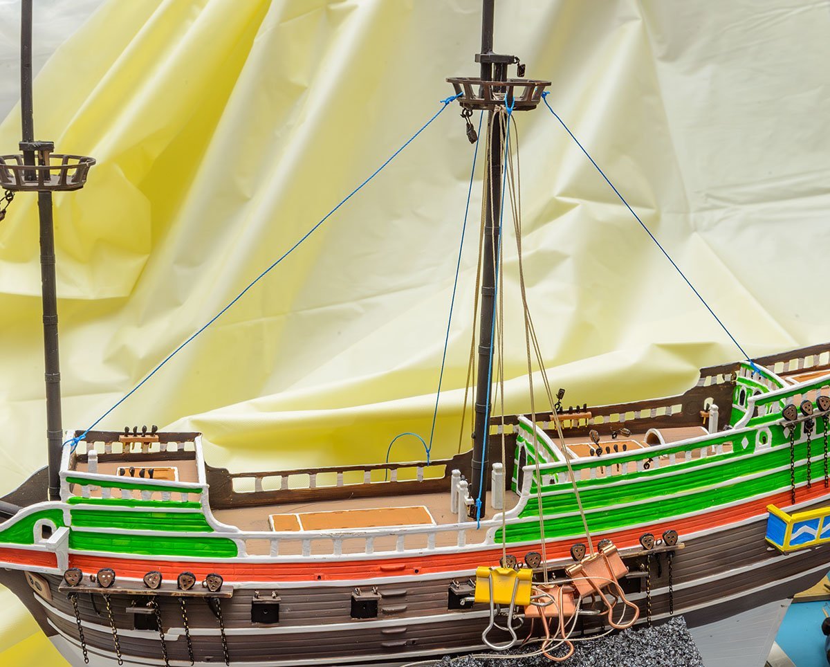
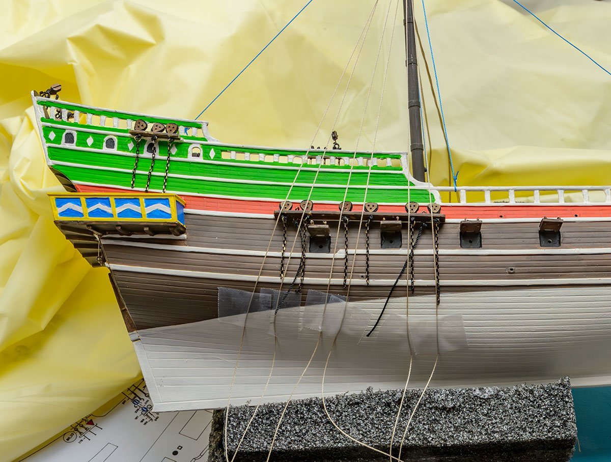
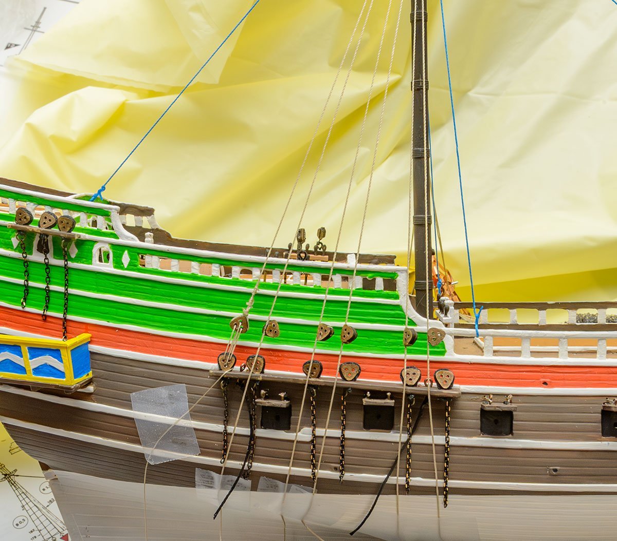
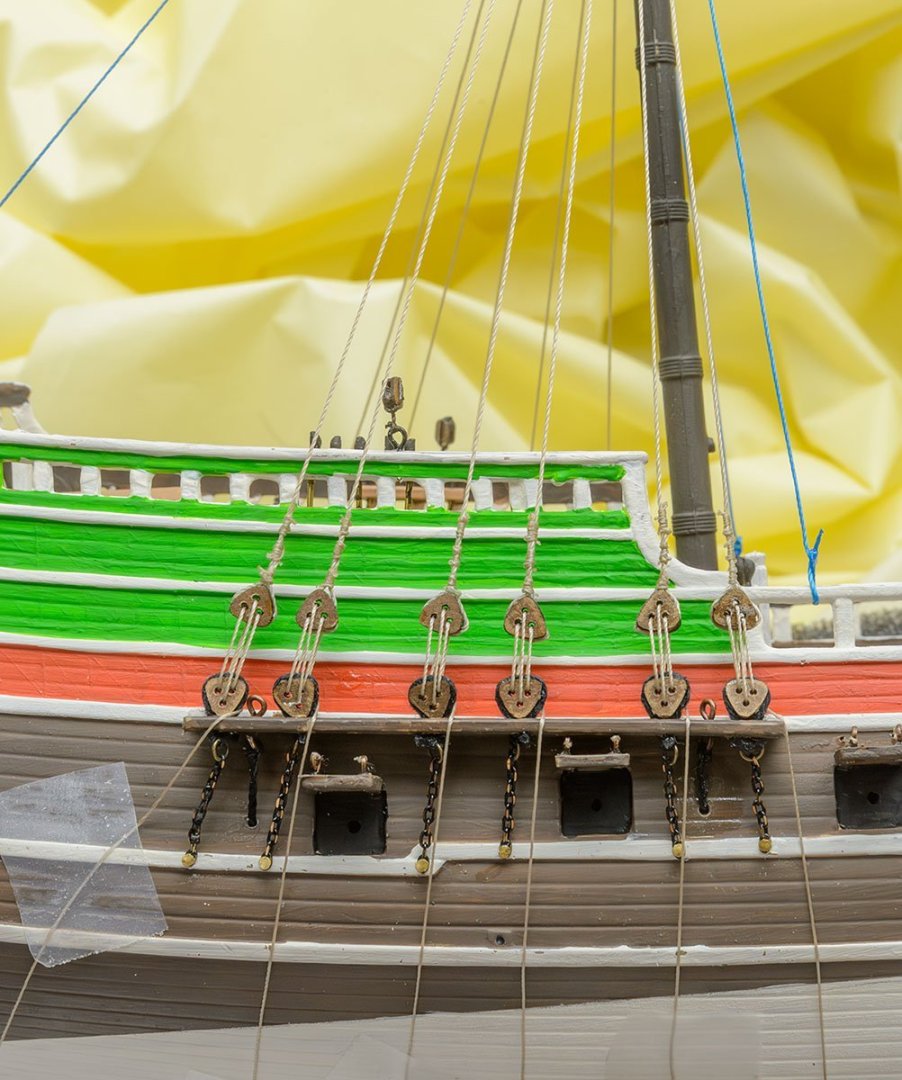
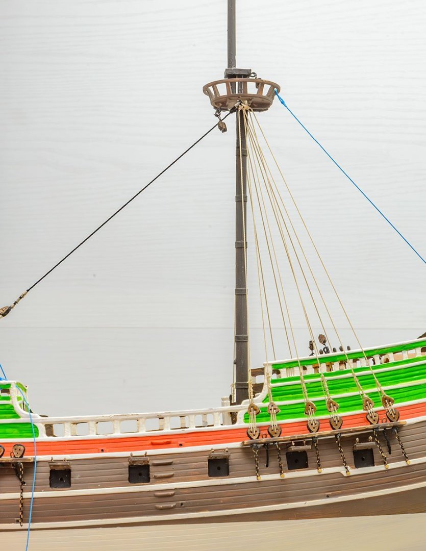
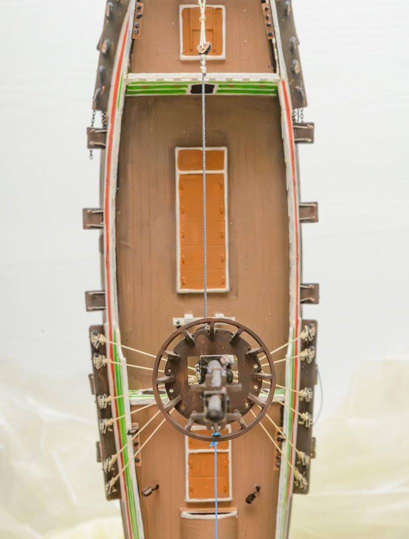
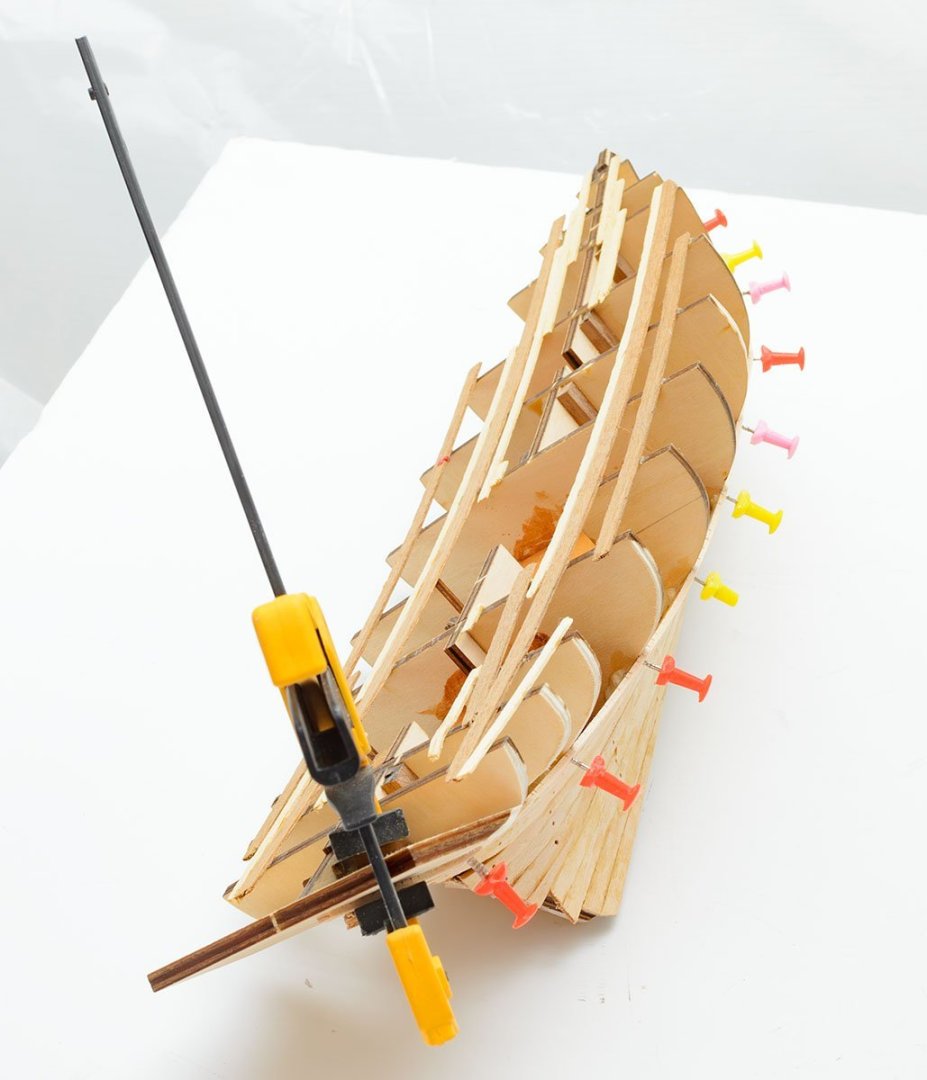
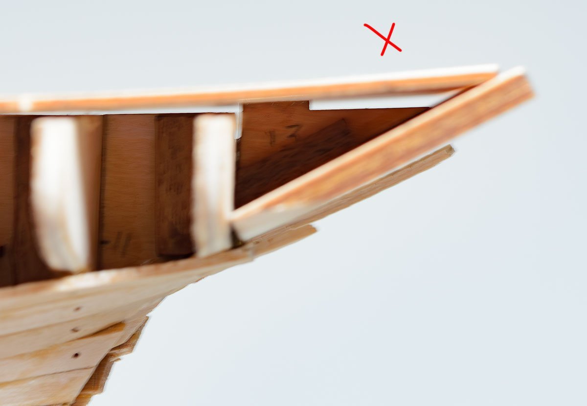
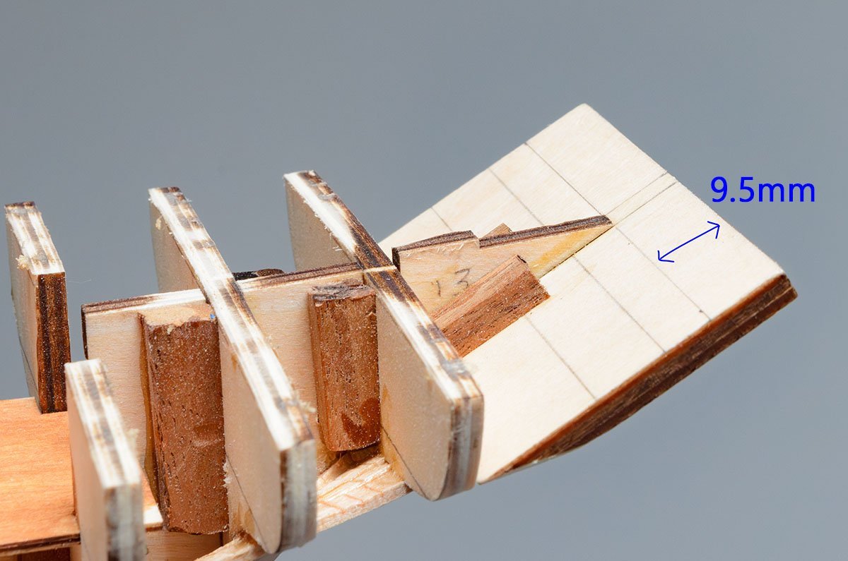
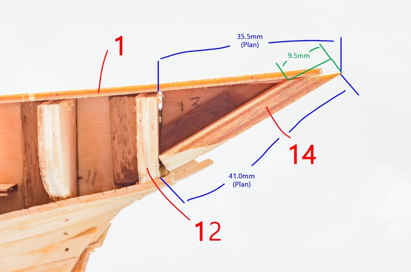
In general, the kit is very friendly to moding. It looks like a simplified version of a wooden model ship. Only a few parts are not good, like the position of the bowsprit. I finished tyhe hull modification. The rigging plans aren't matched with this kit well, and the old plans are very hard to read. I miss AL's manual. It is time to rig shrouds. The blue threads are temporary. I finished ¼ of shrouds. I pulled the shrouds a bit much. The alignments of deadeyes aren't good. See you next time. 😎
- 13 replies
-
- 3
-
-
- Golden Hind
- Airfix
- (and 1 more)
-
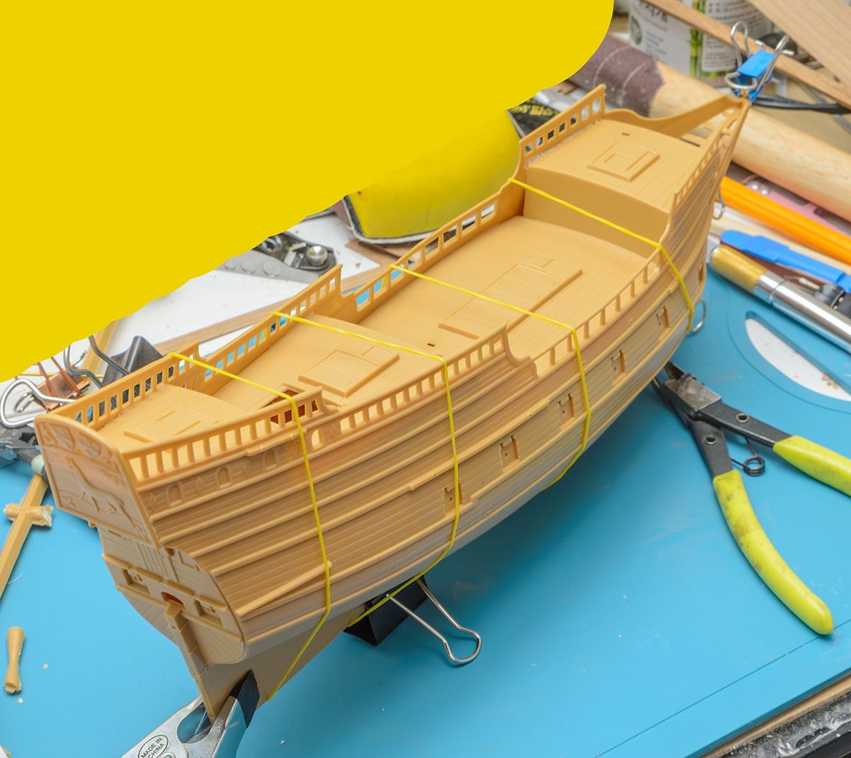
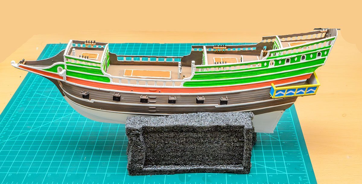
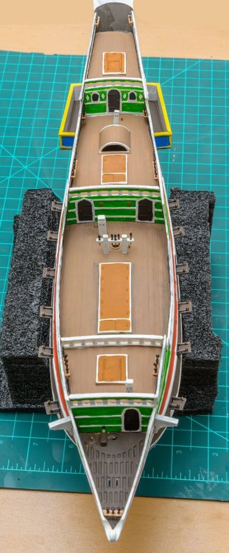
The Airfix Golden Hind 1/72 kit is a 50 years old vintage kit. I bought this kit to practice rigging Galleons. https://www.hismodel.com/golden-hind-6 This is my reference for rigging practice. I know the rigging plans aren't equal to my kit, so I'm fixing some parts of the plan. I did basic paintings only. The Golden Hind has no reference, so we don't know exactly what color it was. Skipping hull building is an advantage of the plastic kit. The painting is done. I added belaying pin racks. I made belaying pins using brass rods and high viscosity (sticky) CA glue. Also, I designed 15 species 310 blocks for Golden Hind. Laser cut And assembly. 😭 I'm still modifing many parts. It is not easy to get started on rigging ASAP as I planned... I hope companies like Eduard make detail up parts for specific plastic kits.


- 13 replies
-
- 6
-
-
- Golden Hind
- Airfix
- (and 1 more)
-
Thank you for your kind words, Marco. Your paper model ships are incredible. I feel I'm on the starting line of paper model world. Also, I appreciate your comment, Nils. By the way, you should check your signature links. Your current build is linked to this article. (The link changes by webpage.)
-
CNC Desktop Router Reviews
modeller_masa replied to tmj's topic in CAD and 3D Modelling/Drafting Plans with Software
It depends on your purpose. In my case, the laser cutter does a major part of my work, like cutting strips. I purchased several CNC routers, but I use them only when I engrave or carve 3D shape, or use it like a milling machine when I cut gratings. I would invest more money in a large and stronger laser cutter. I'll pay only $200 for a CNC router, or buy 4 or 5 axis expensive router to carve figure heads. (Actually, the figure heads can be made by a 3D resin printer. ) -
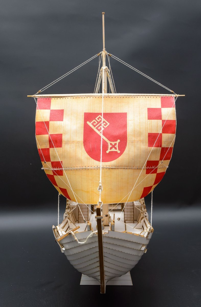
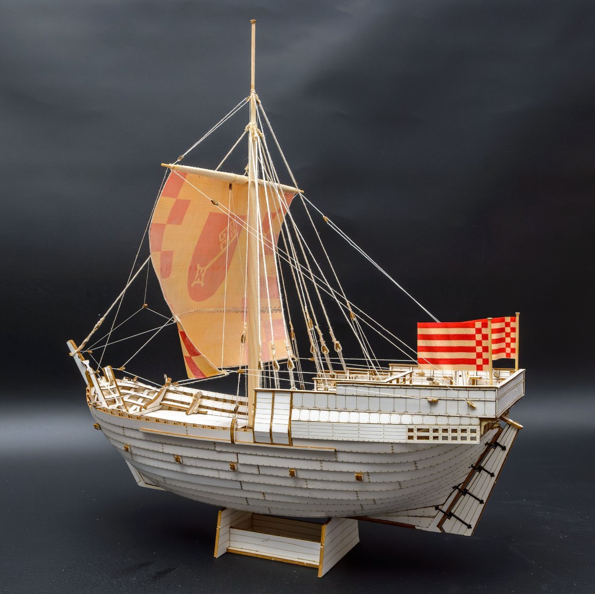
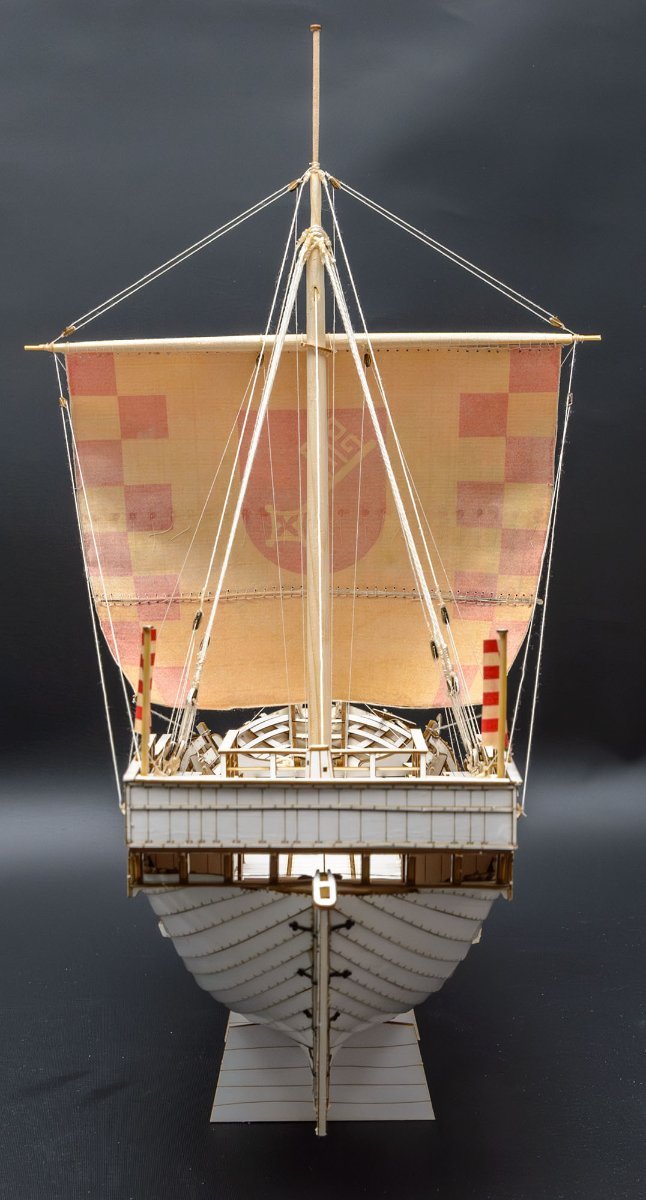
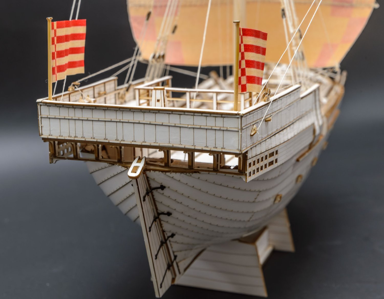
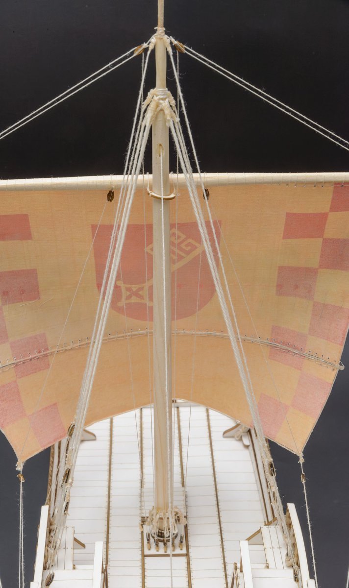
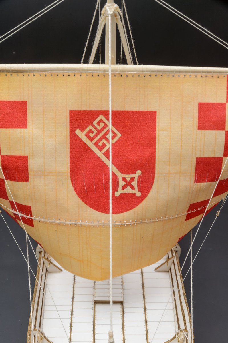
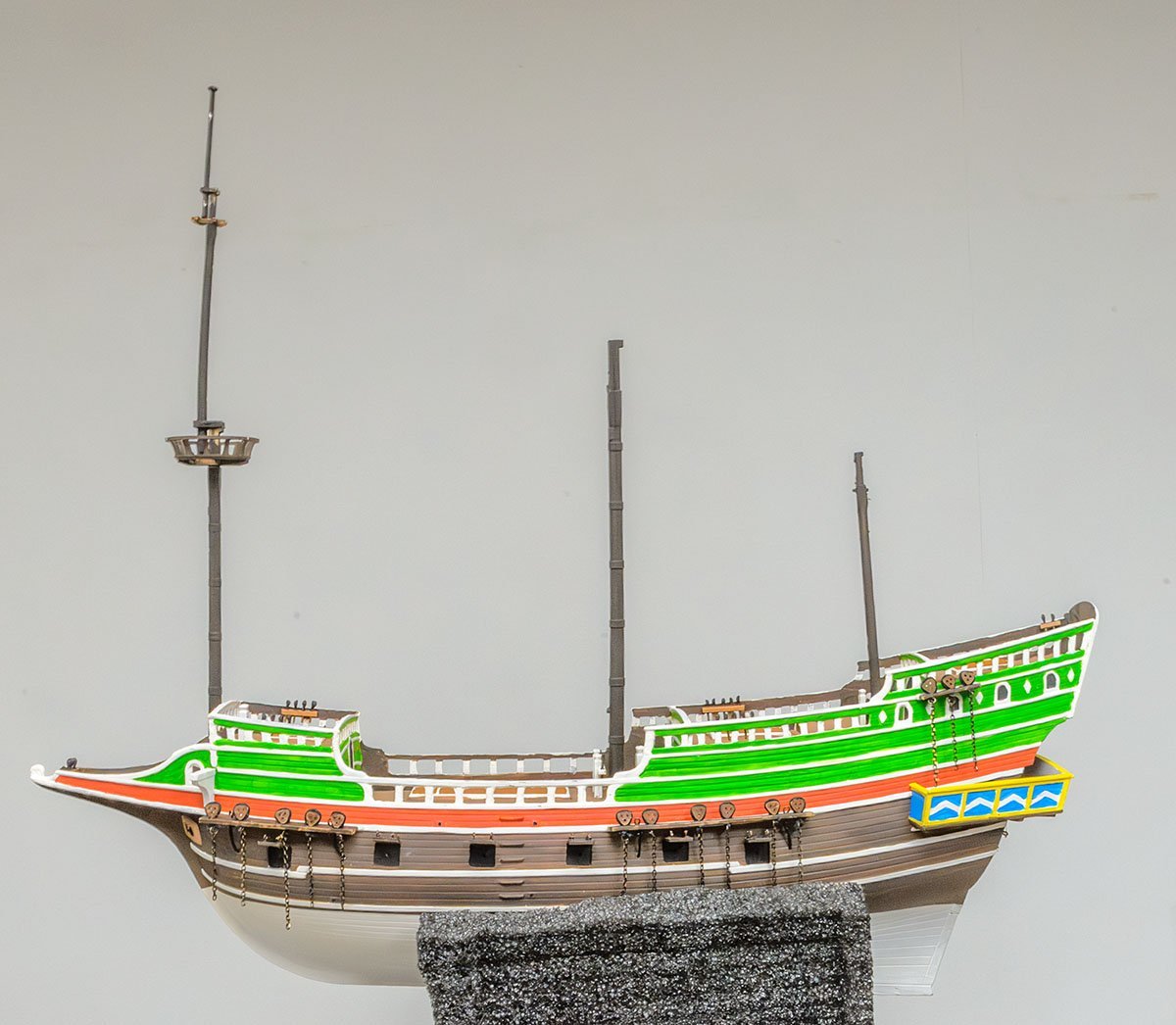
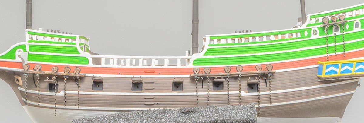
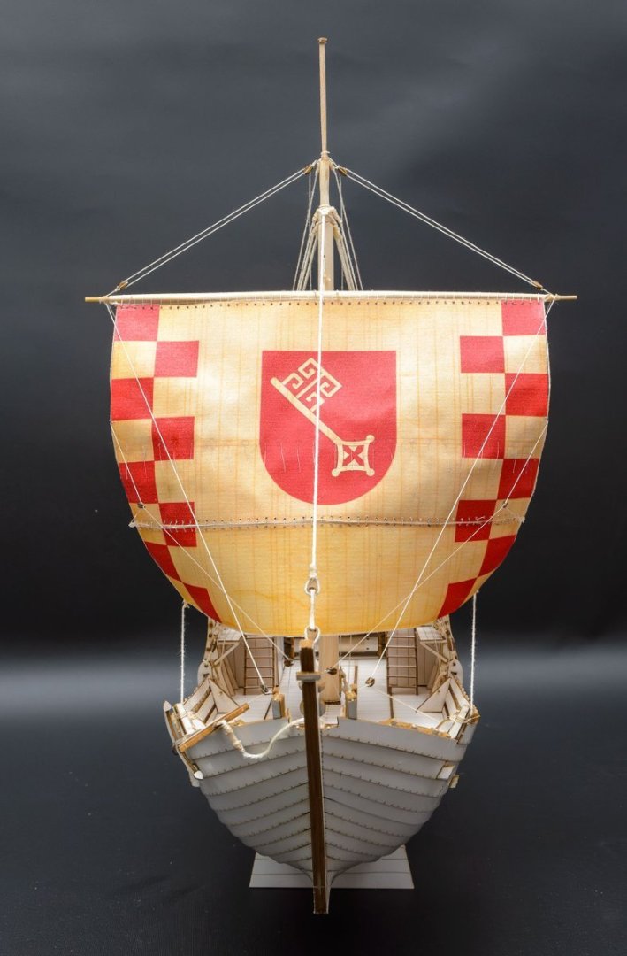
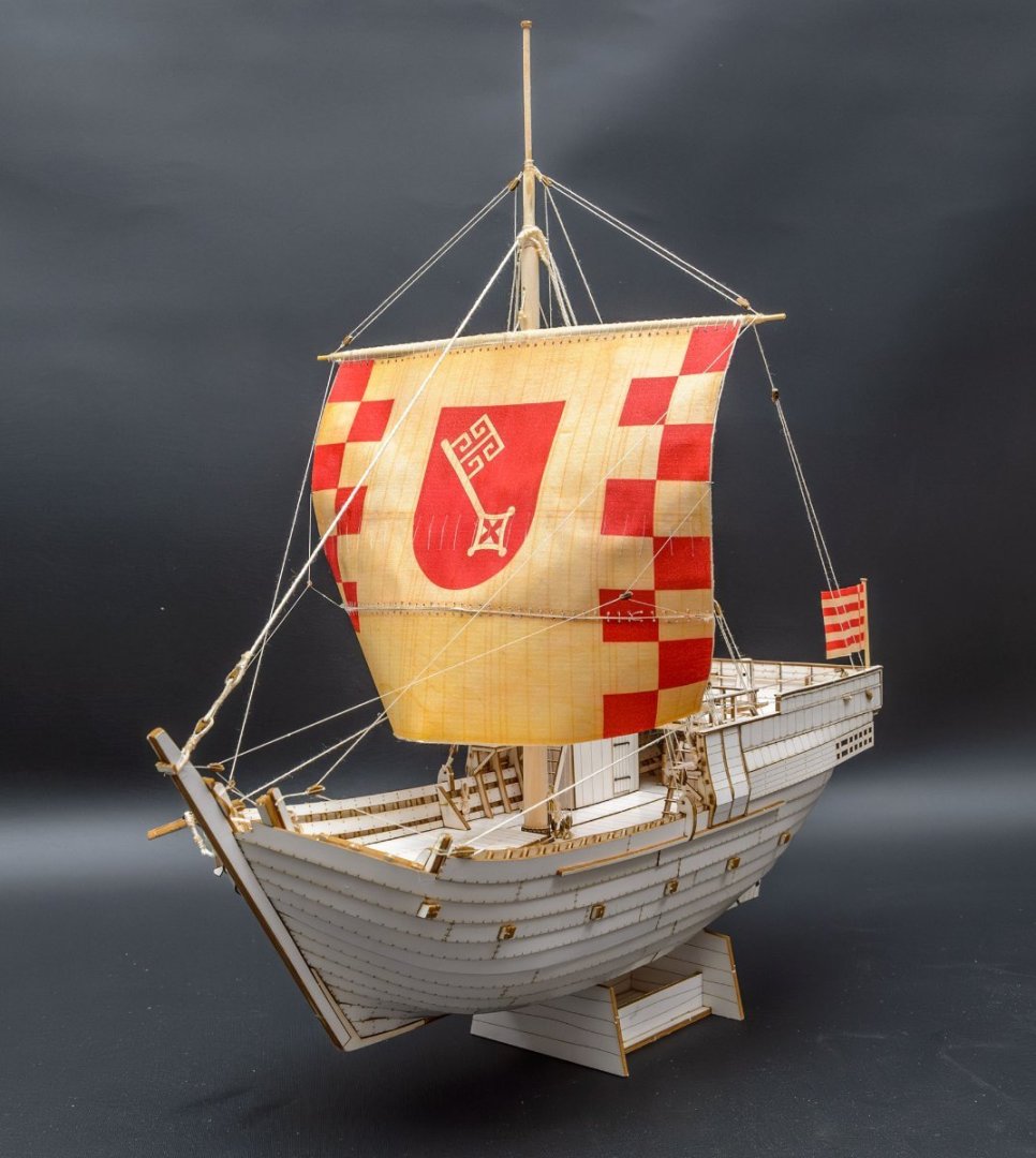
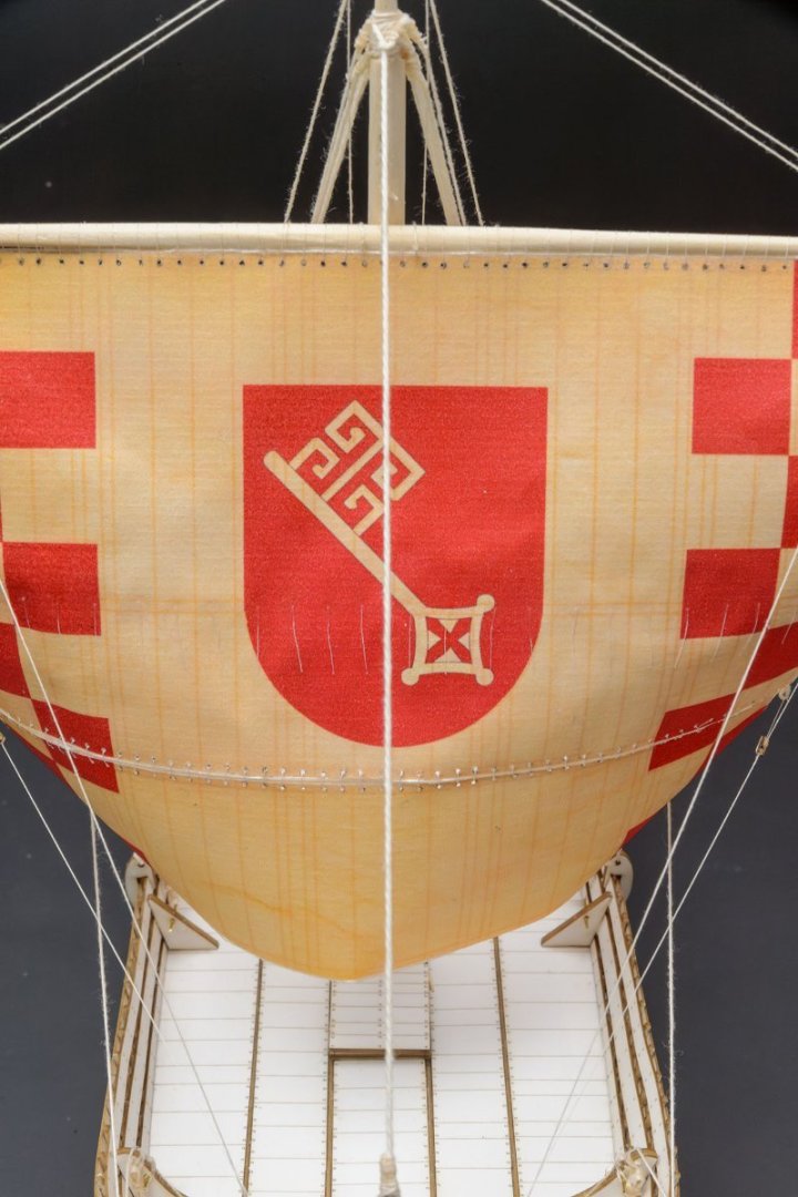
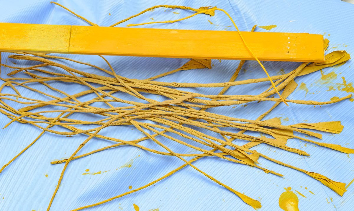
Because I failed to build the Papegozan (Shipyard, ZL-005), I made the Hanse Kogge (Shipyard, ZL-048) in a week without painting. I found what was wrong and what I had missed before. - The Hanse Kogge (ZL-048) is a much more advanced kit than the old Papegozan (ZL-005). HK has two manual books, and the instructions are much clear and helpful. - The HK instructions has a very simple and fast painting method. I don't worry about painting anymore. - The method of assembly is much improved. The HK kit isn't a high-priced laser cut paper model. It is something in the middle of paper model kits and plastic model kits. If I had built the HK kit first, I wouldn't have failed the Papegozan kit. I recommend this kit as the best introductory kit for early Shipyard kits.


-
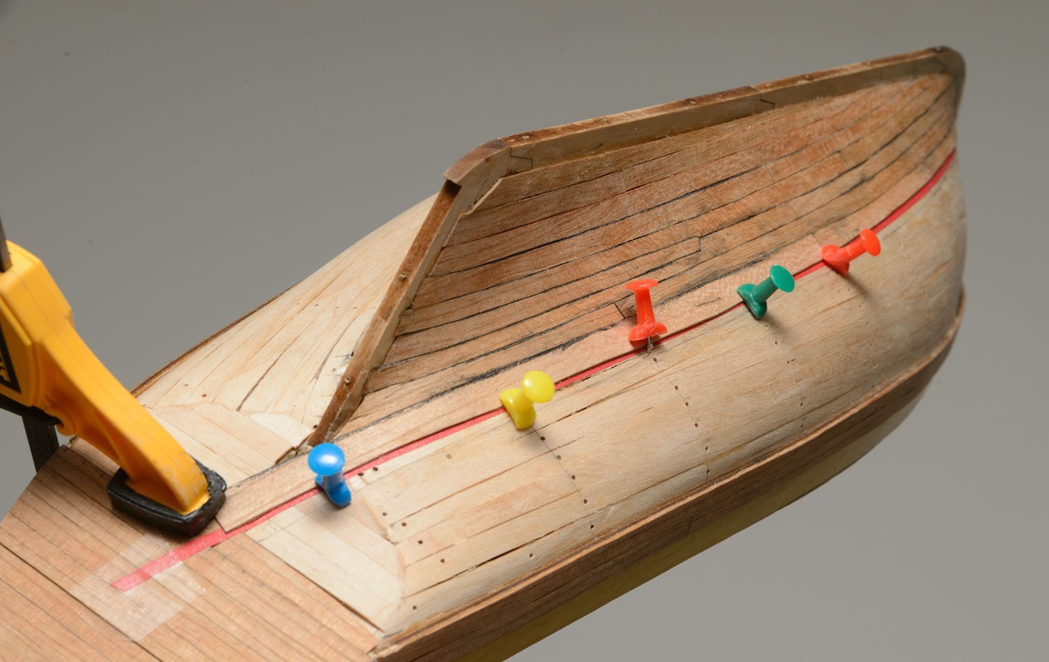
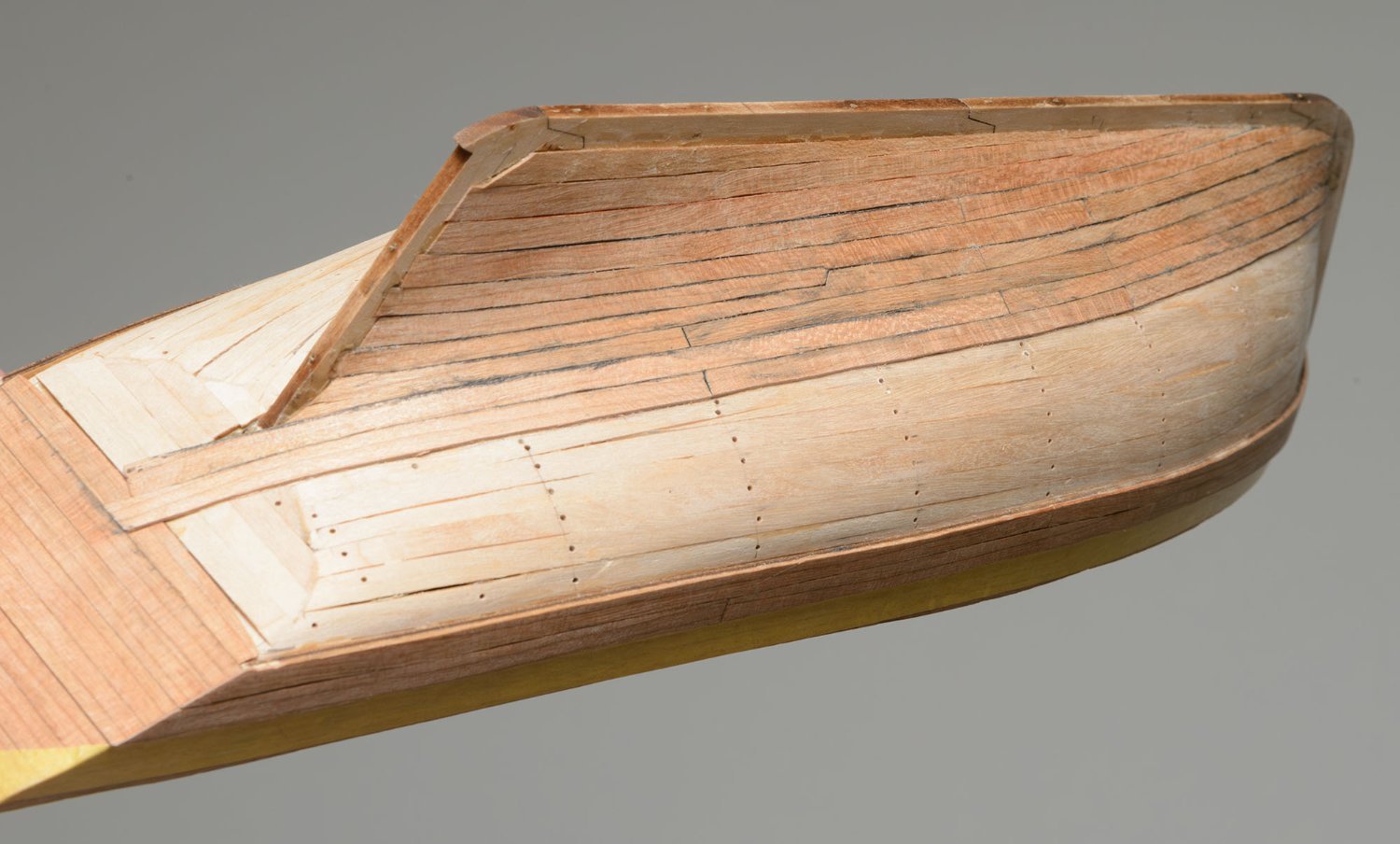
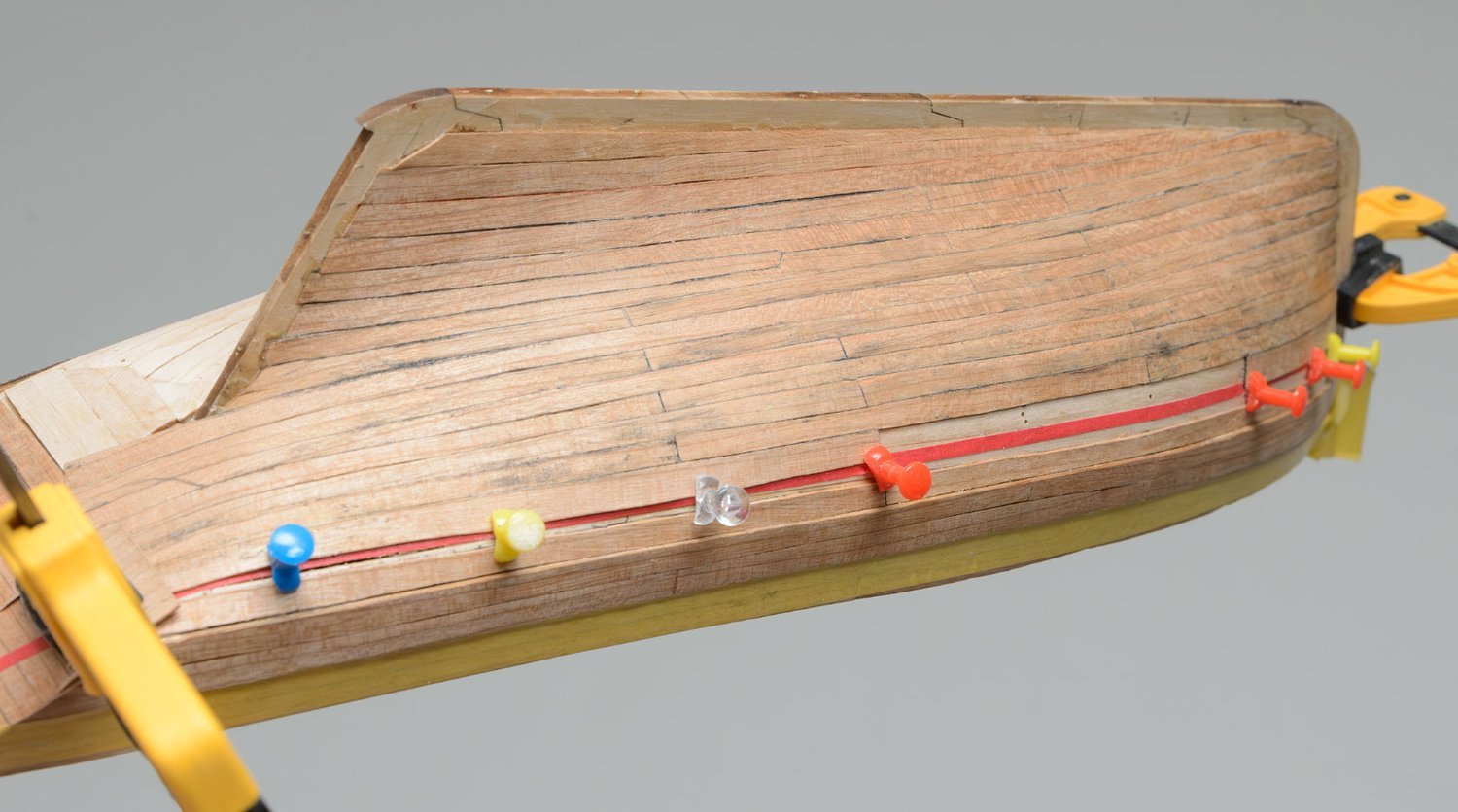
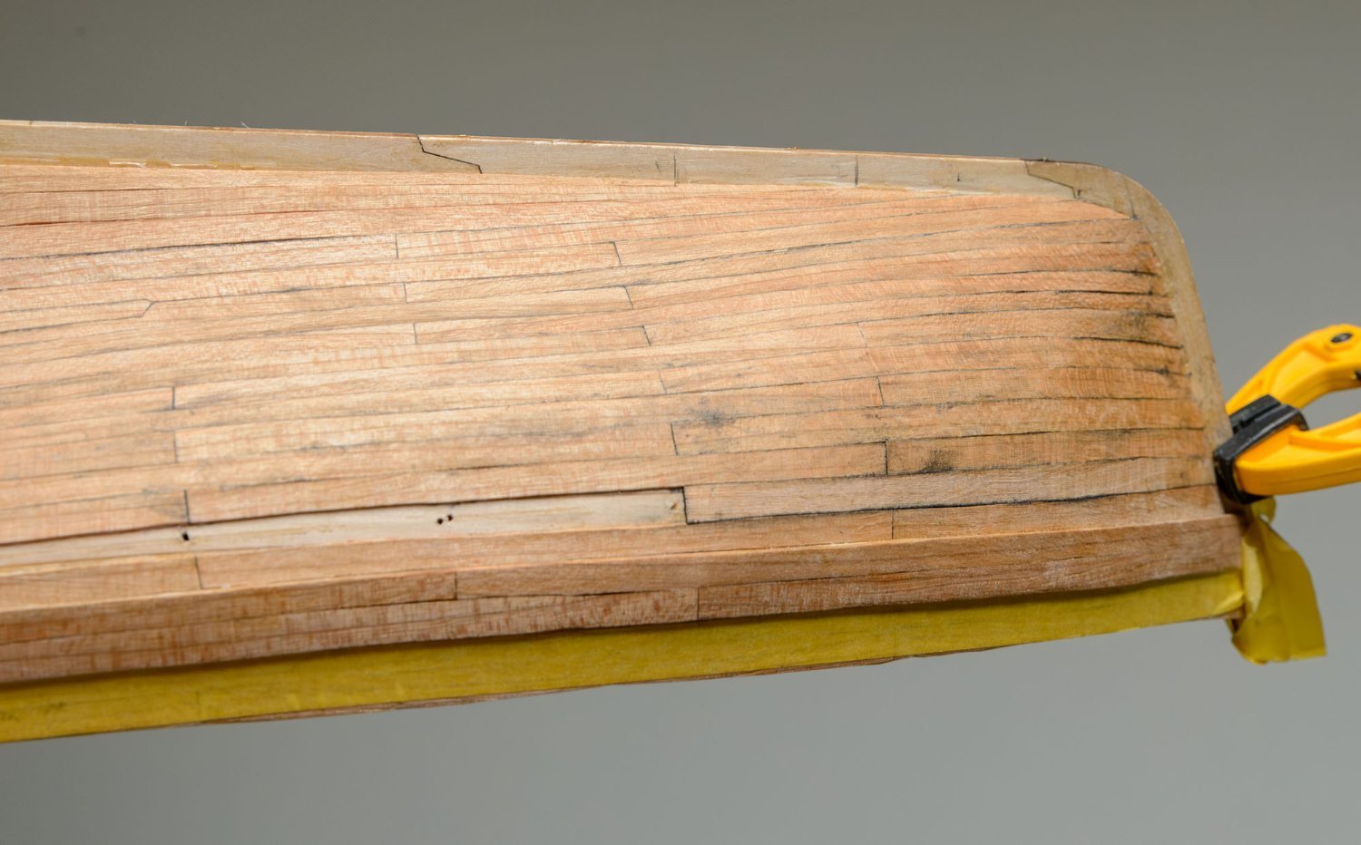
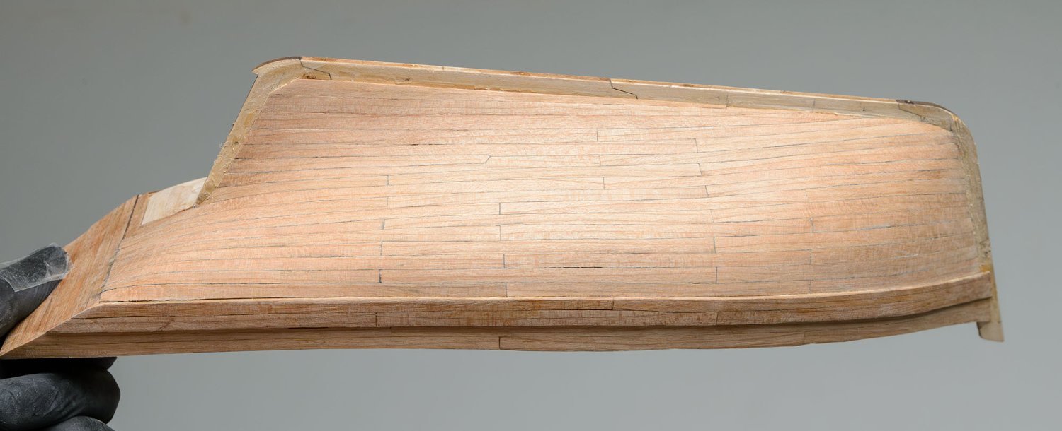
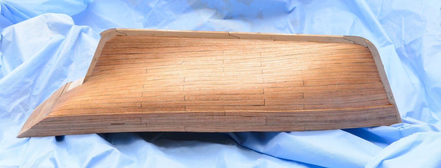
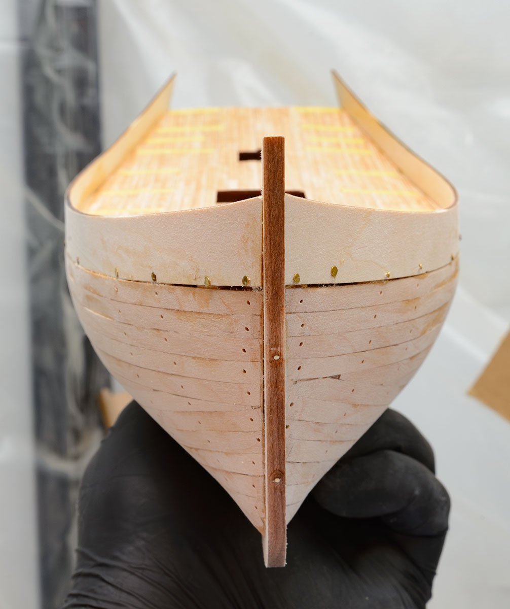
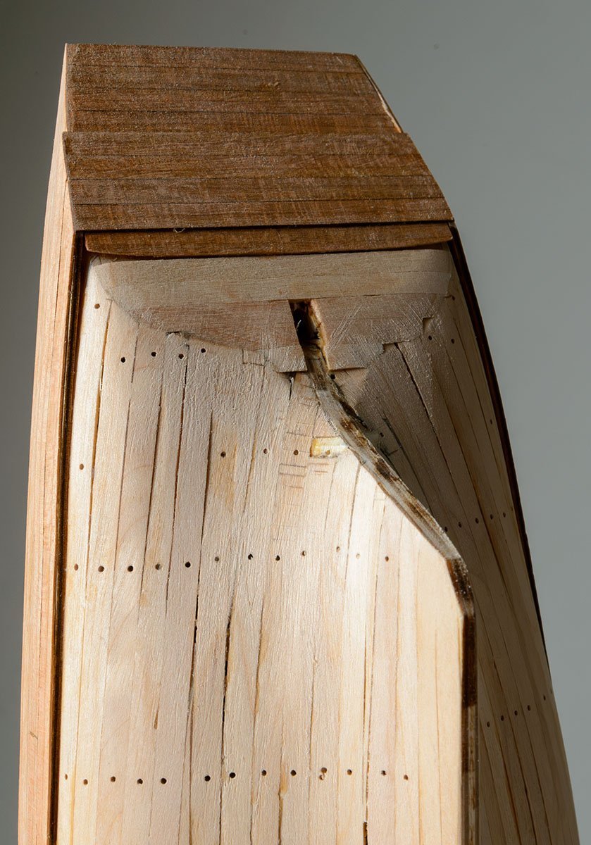
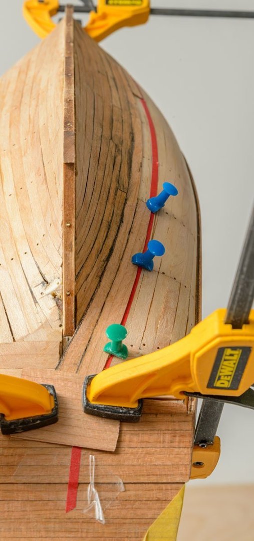
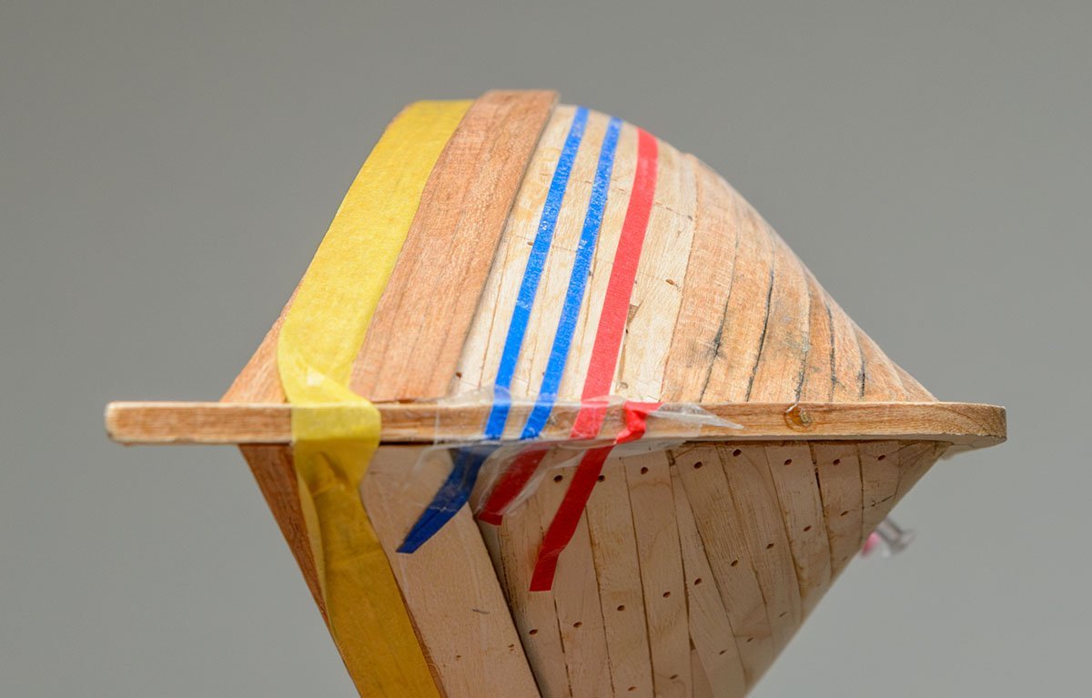
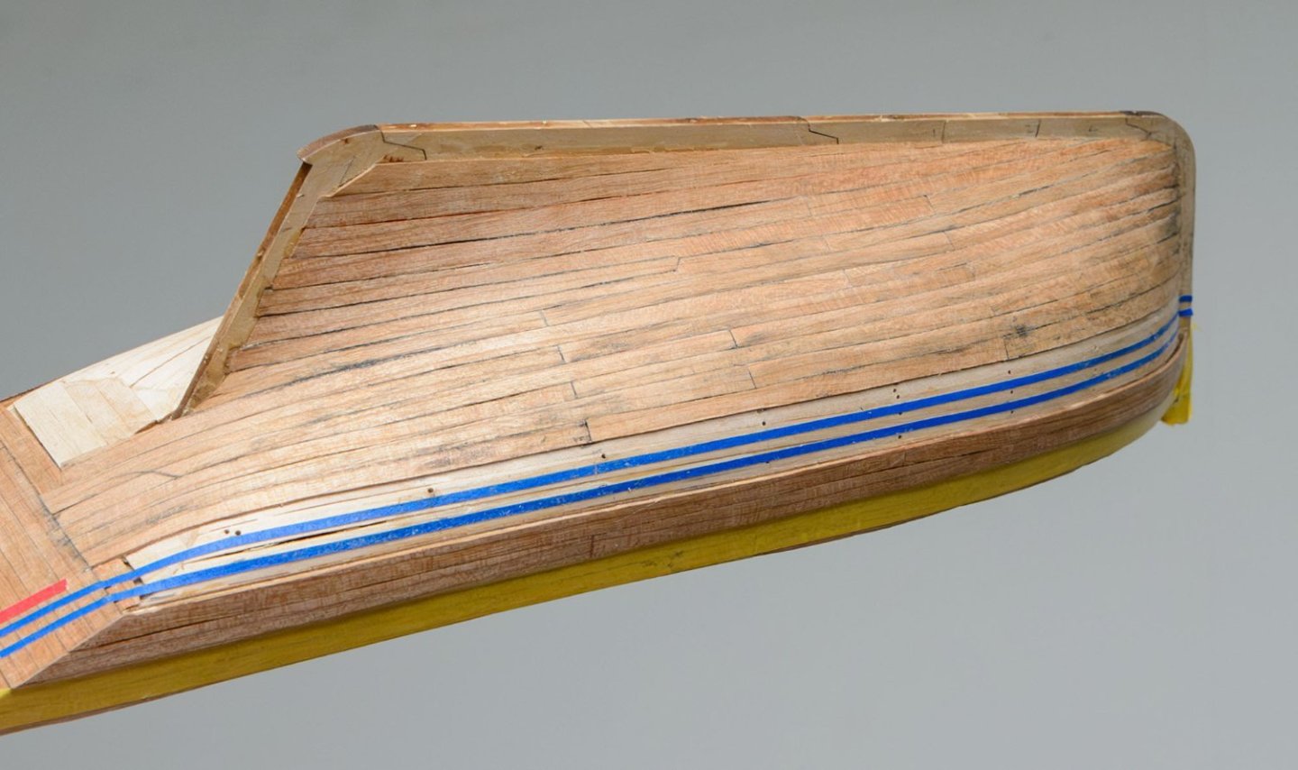
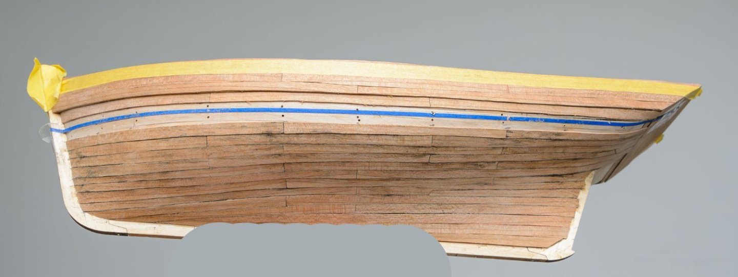
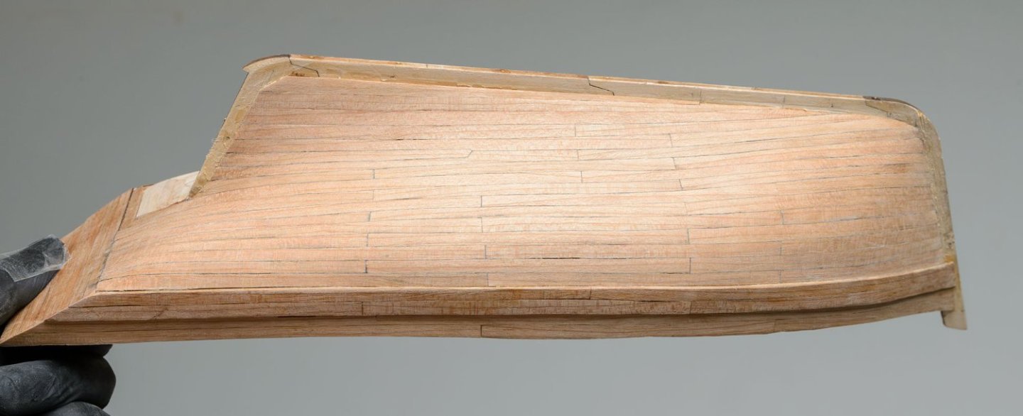
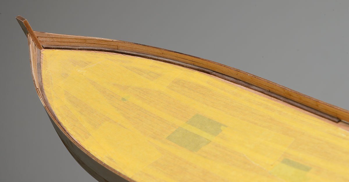
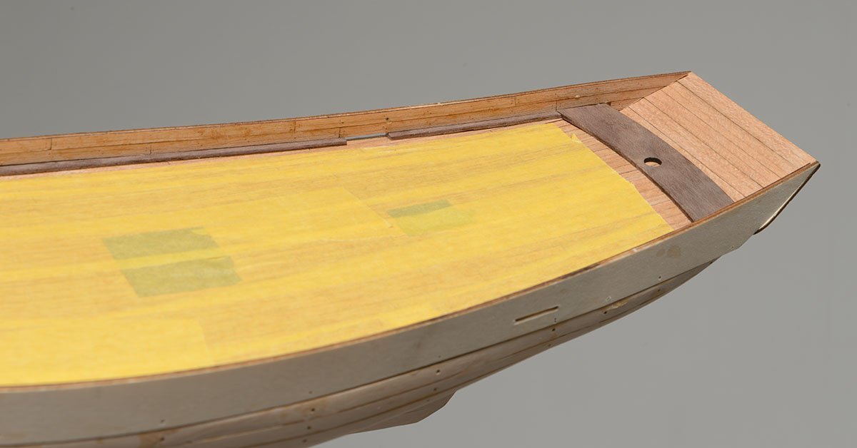
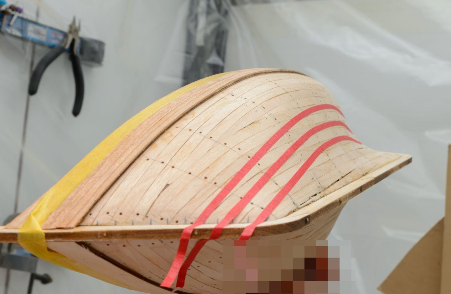
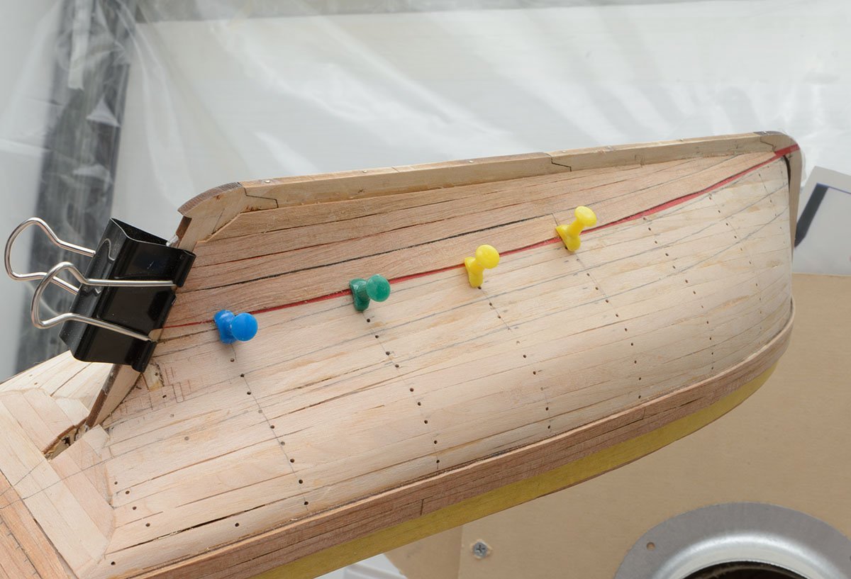
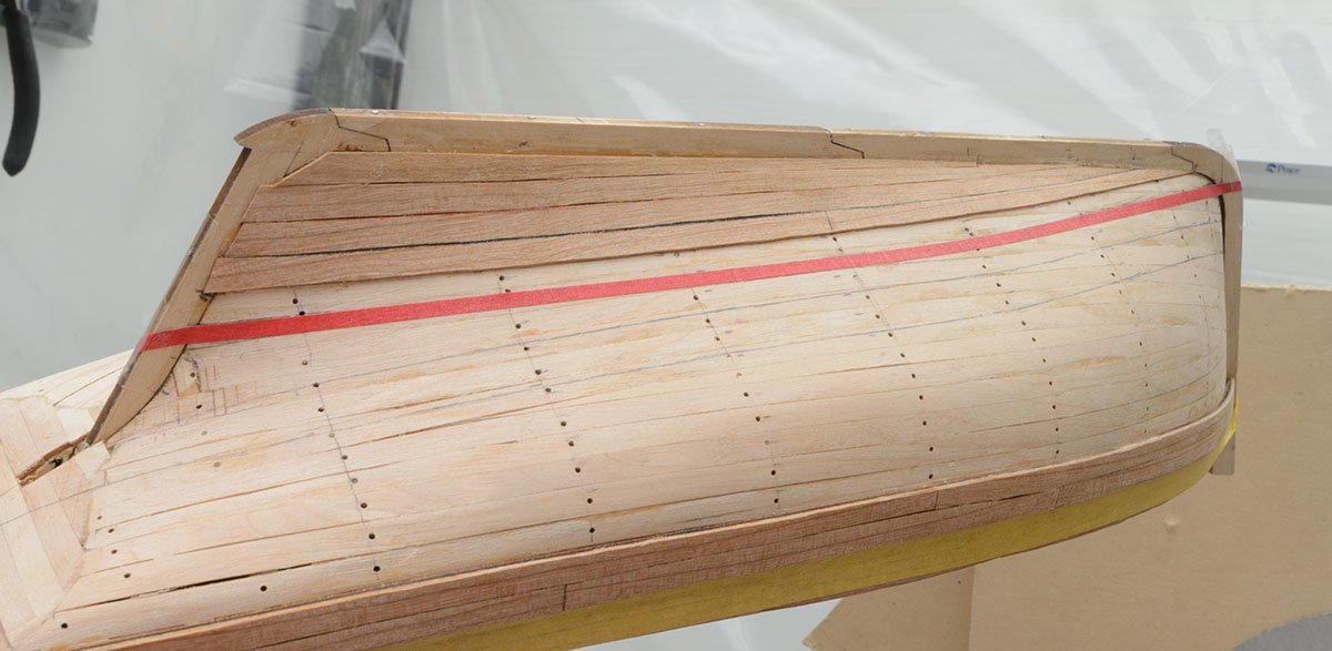
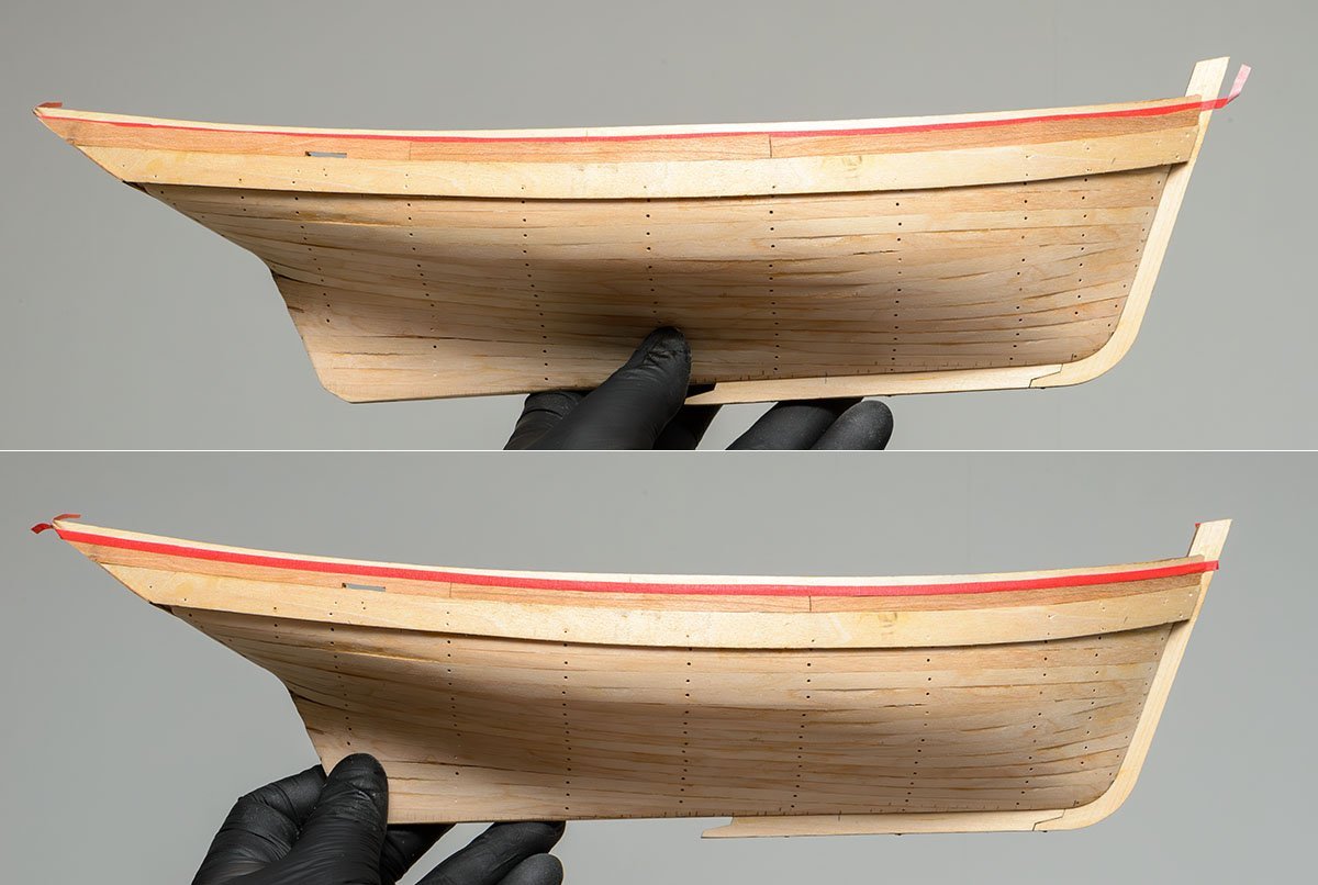
I finished the port side. f The lower section and the middle section are finished. The last section has 7 planking lines. The latest planking line is a little tricky. No clamping. I held it by hand. I slightly sanded the surface. I used a black oil pastel to show caulking. After I sealed the surface using dewaxed shellac, I attached making tape to protect it. I'm already halfway through.


- 17 replies
-
- 6
-
-
- Marie-Jeanne
- Artesania Latina
- (and 1 more)
-
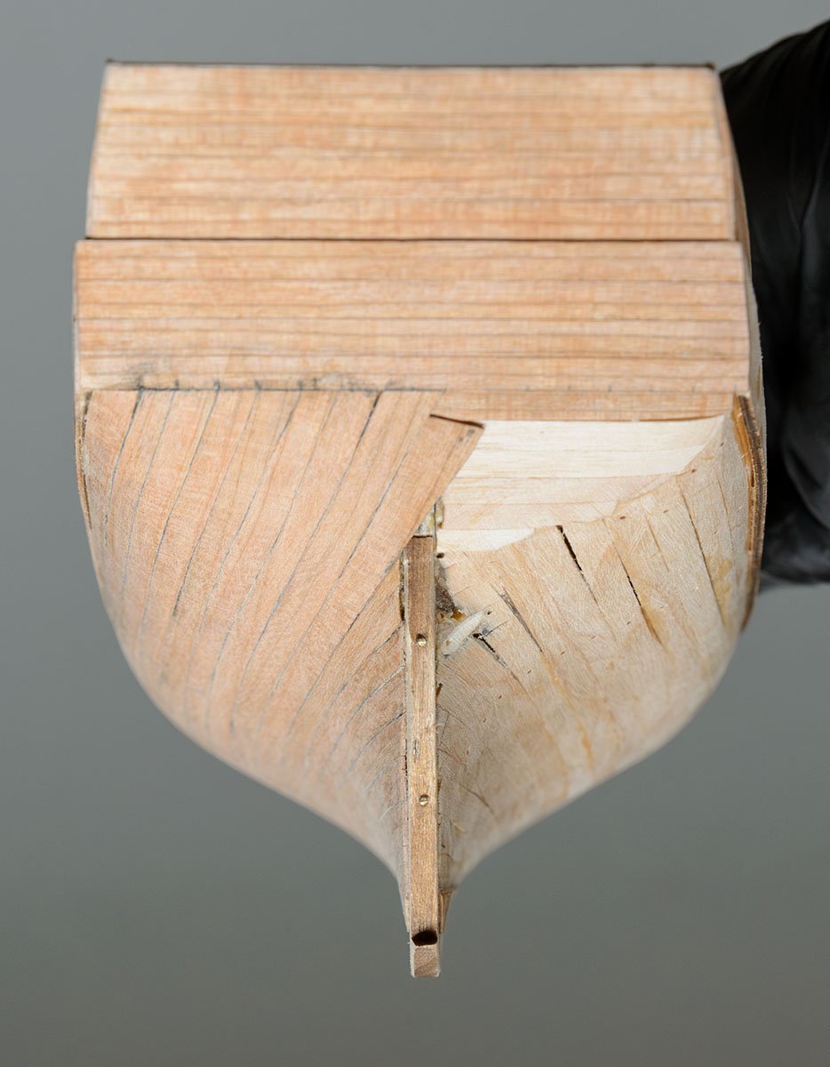
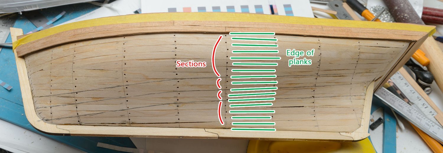
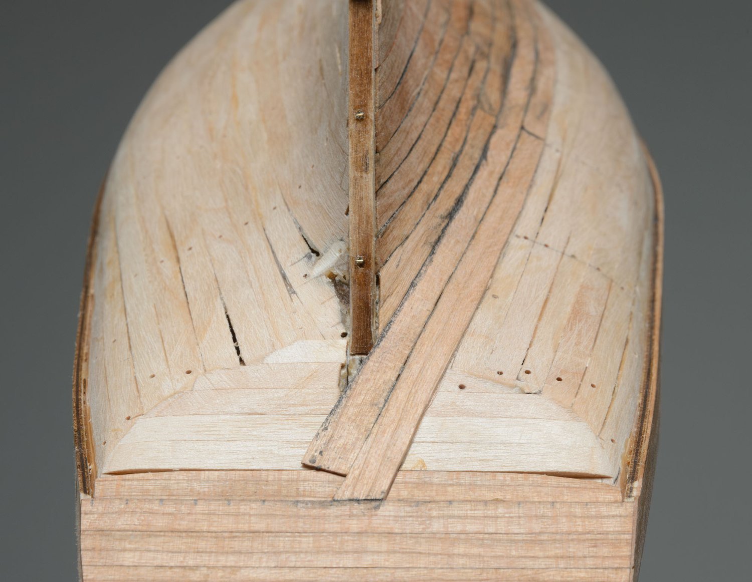
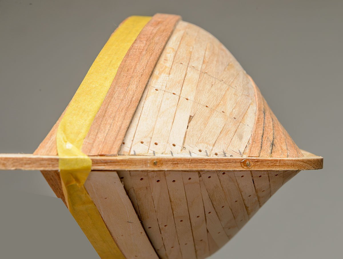
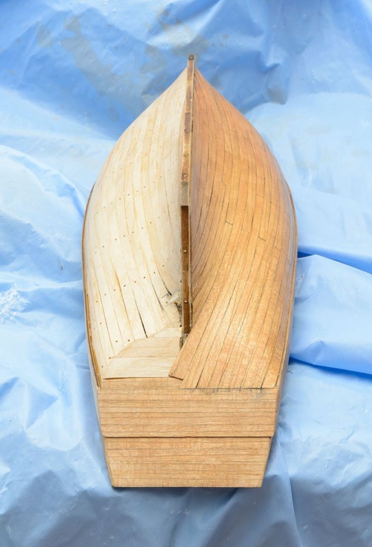
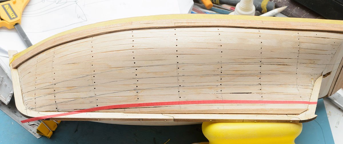
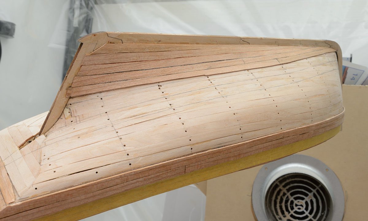
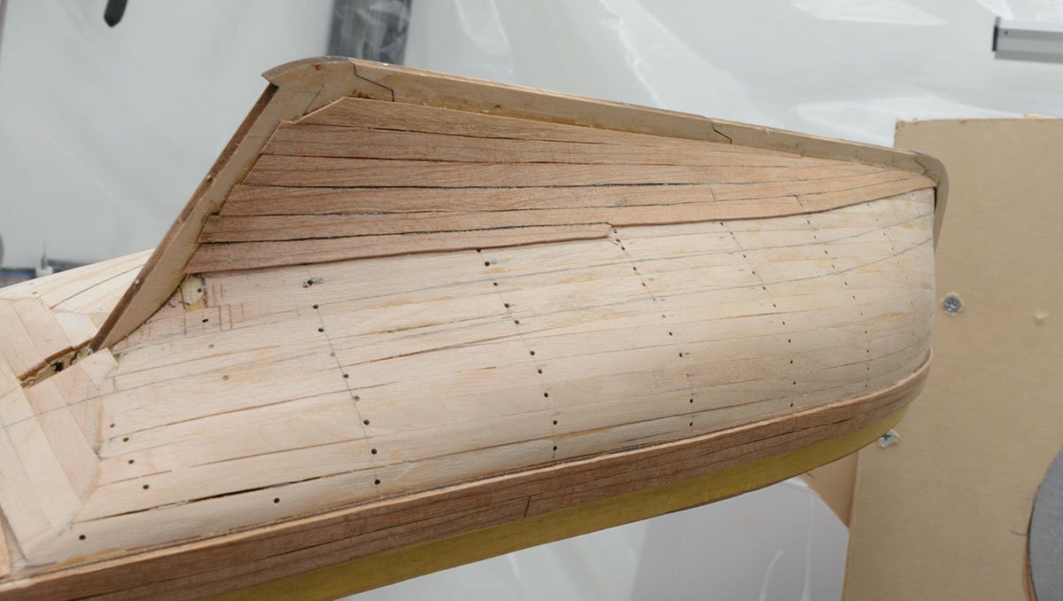
There is a little planking inside of bulwark. It is time to build the second planking layer. I traced the Heller kit. I didn't make good planking lines, so I modified it a little bit. After repeated work, I made every planking line. The upper section has 7 flat planks. The middle section has 4 planks with the twisted lines, and the bottom section has 5 planks. I'm running the second planking layer. I used the traditional spiling planking method. Because of wide stern post, I added stealer plank after the fifth plank. Alright. I finished two-thirds of sections.


- 17 replies
-
- 8
-
-
- Marie-Jeanne
- Artesania Latina
- (and 1 more)
-
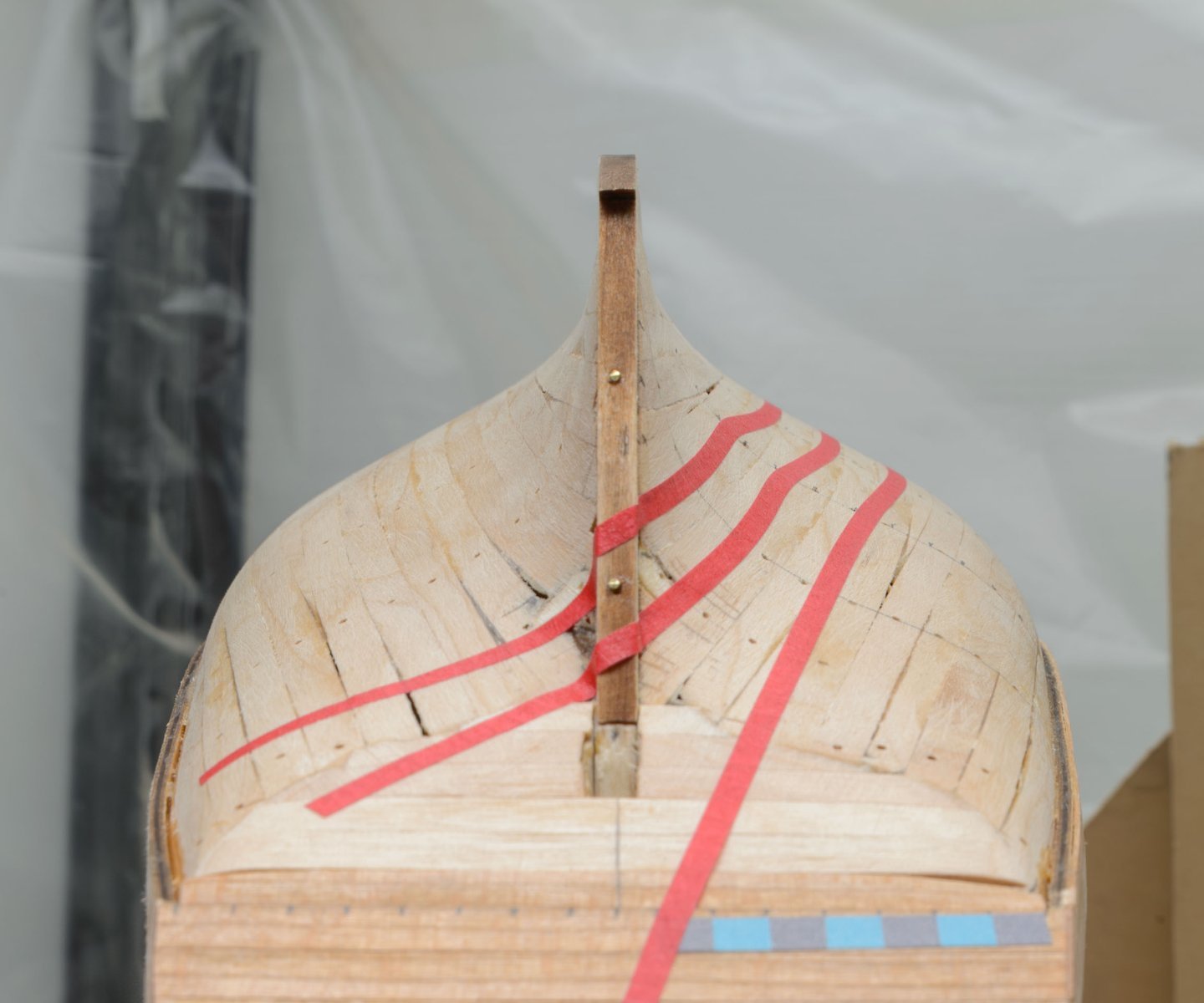
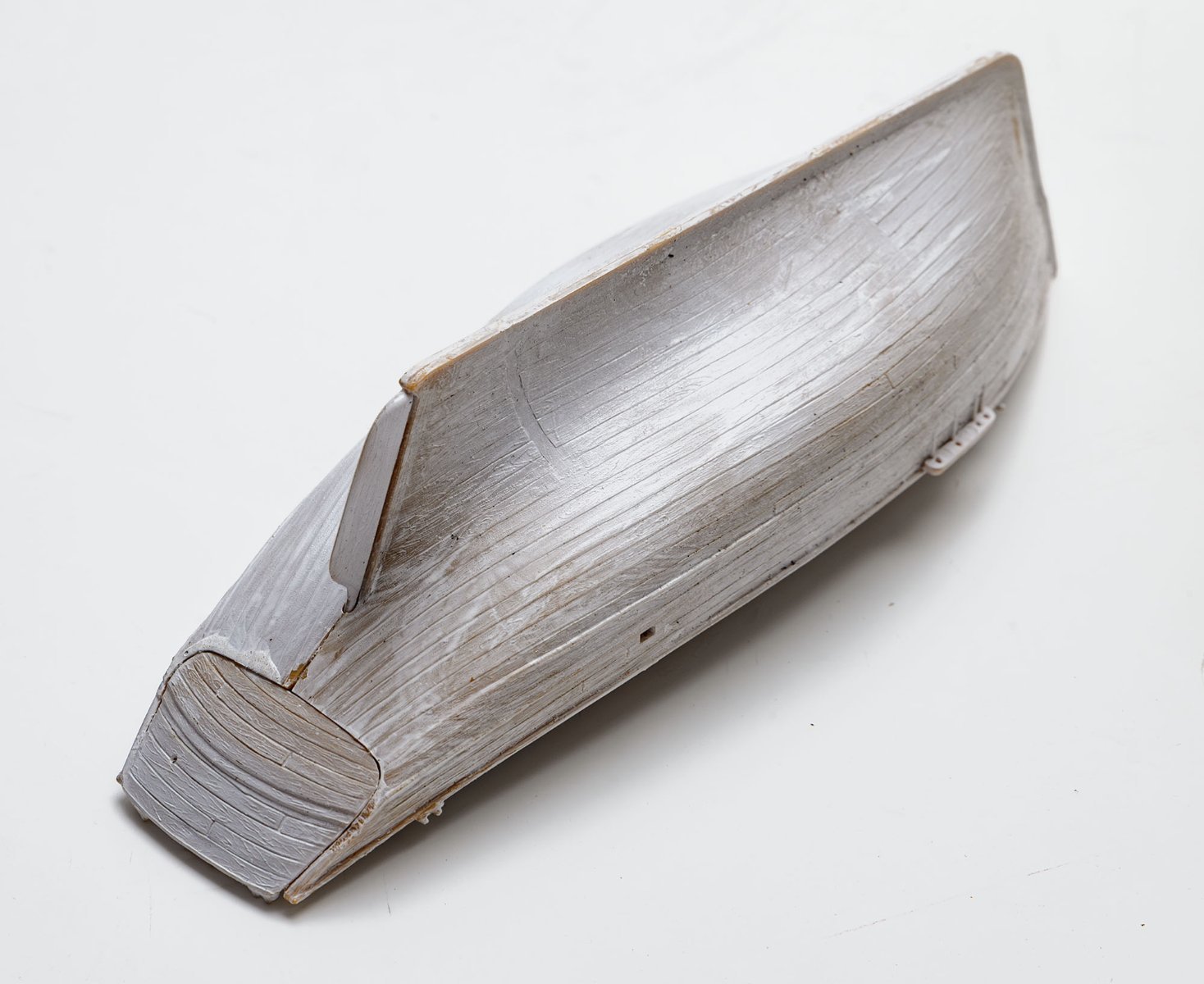
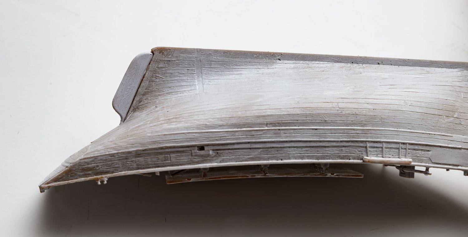
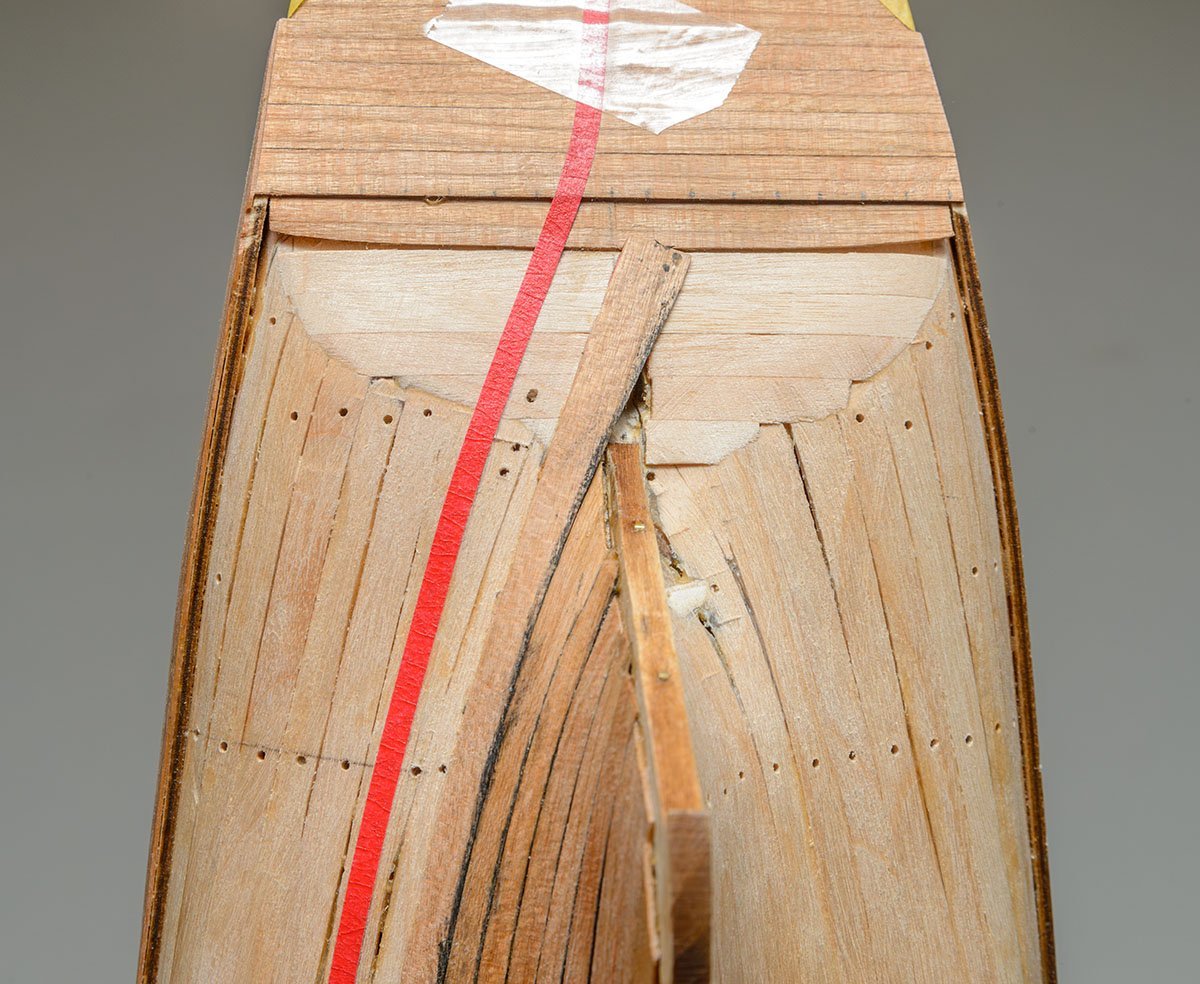
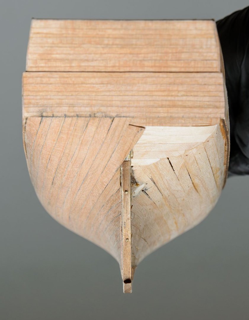
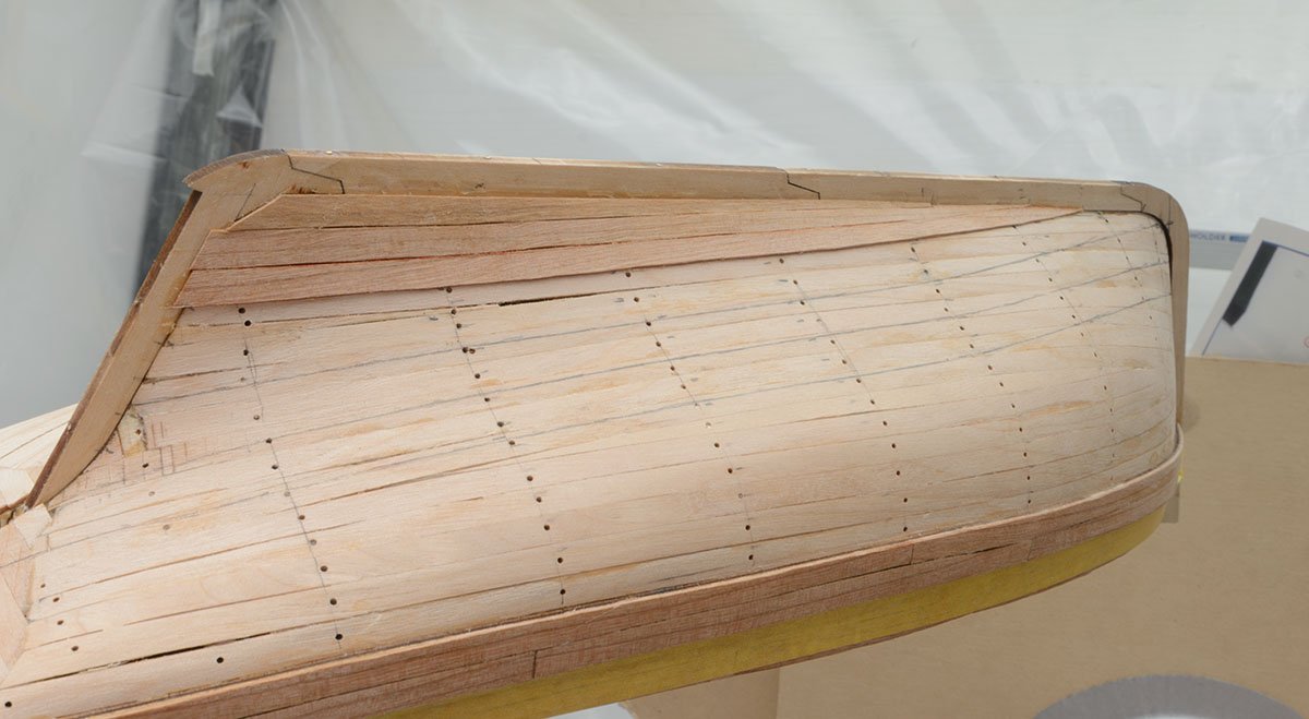
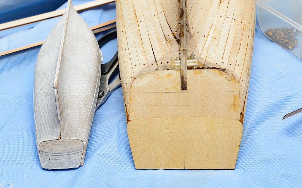
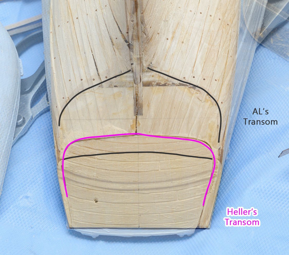
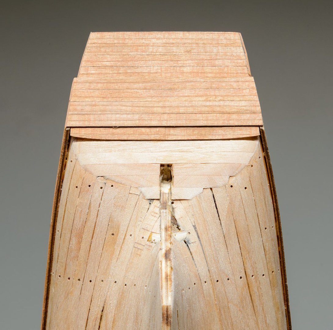
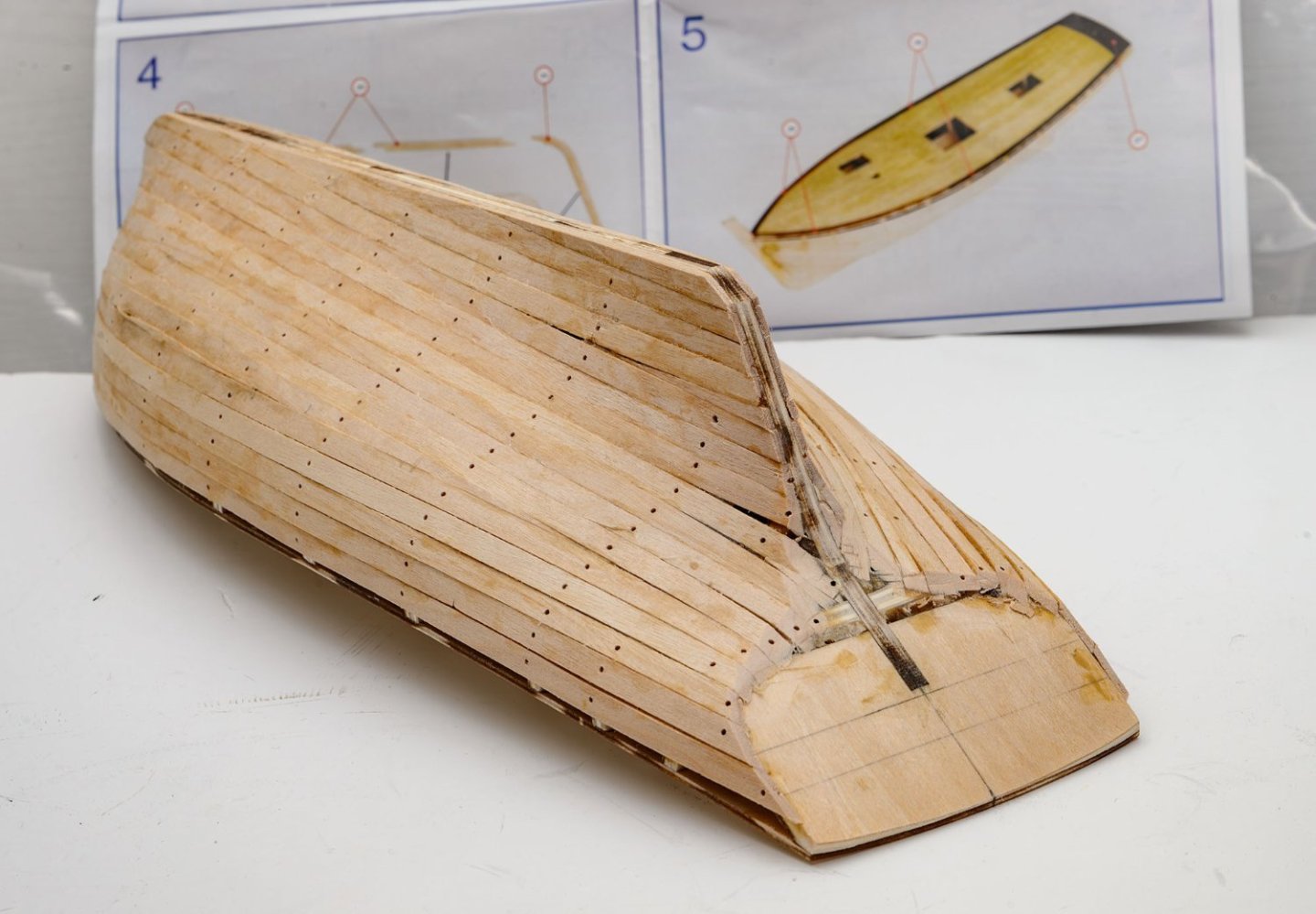
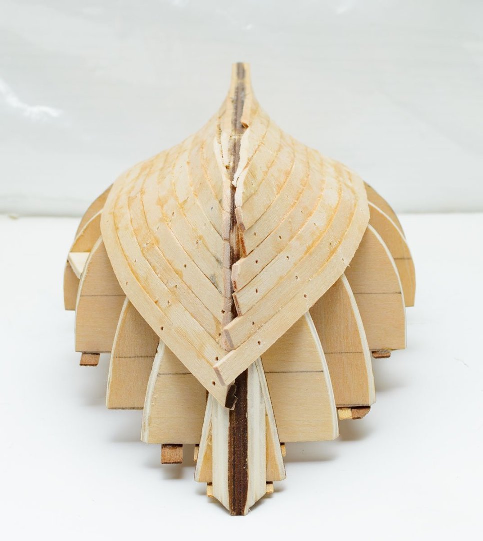
I added only part of keel parts. I didn't determine the stern shape yet. I used brass nails to clamp the bulwark parts. As you see, the transom of the AL kit is very different from the Heller's. Even newer 22175 AL kit has an all-flat transom. I spent a week to decide the transom shape. I added wales to finish transom. Be careful. The location of wales on the 1:1 plan is wrong. Please check the newer 22175 kit's manual. The upper line of the wale parts is the same as the deck's height. I compromised with the transom. My transom has a straight line, unlike the heller's. I finished rear keel and stern post. It is no longer "museum quality." 🤔
.jpg.a889a483b717c4d63bdd8074b18859e3.jpg)


- 17 replies
-
- 2
-
-
- Marie-Jeanne
- Artesania Latina
- (and 1 more)
-
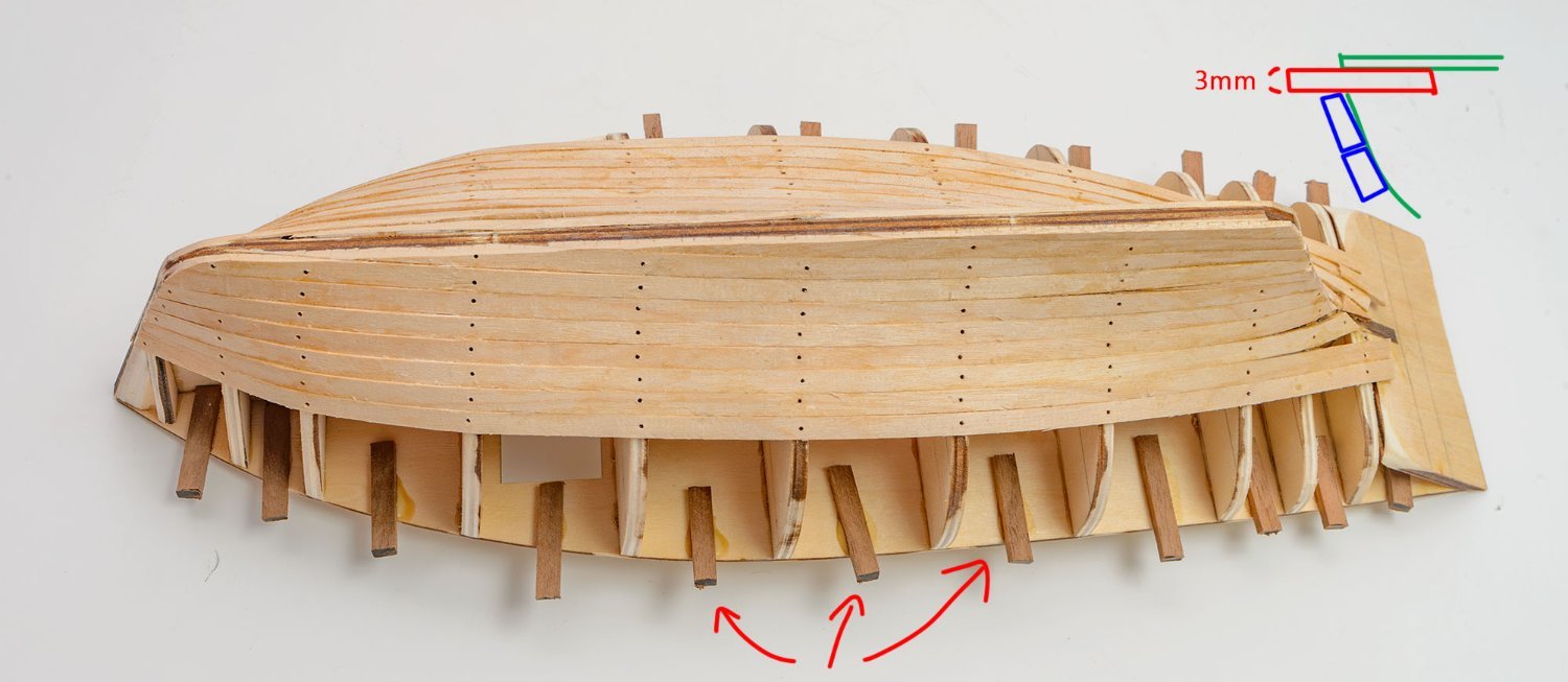
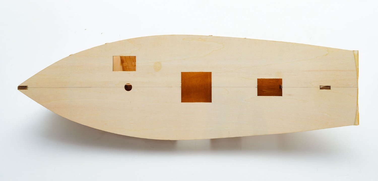
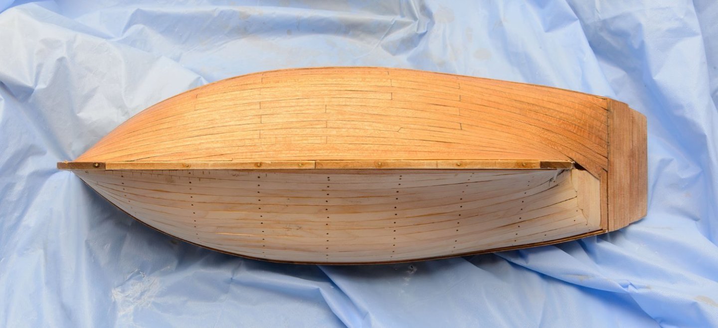
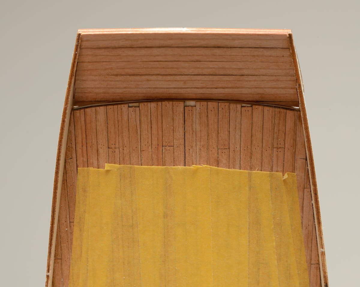
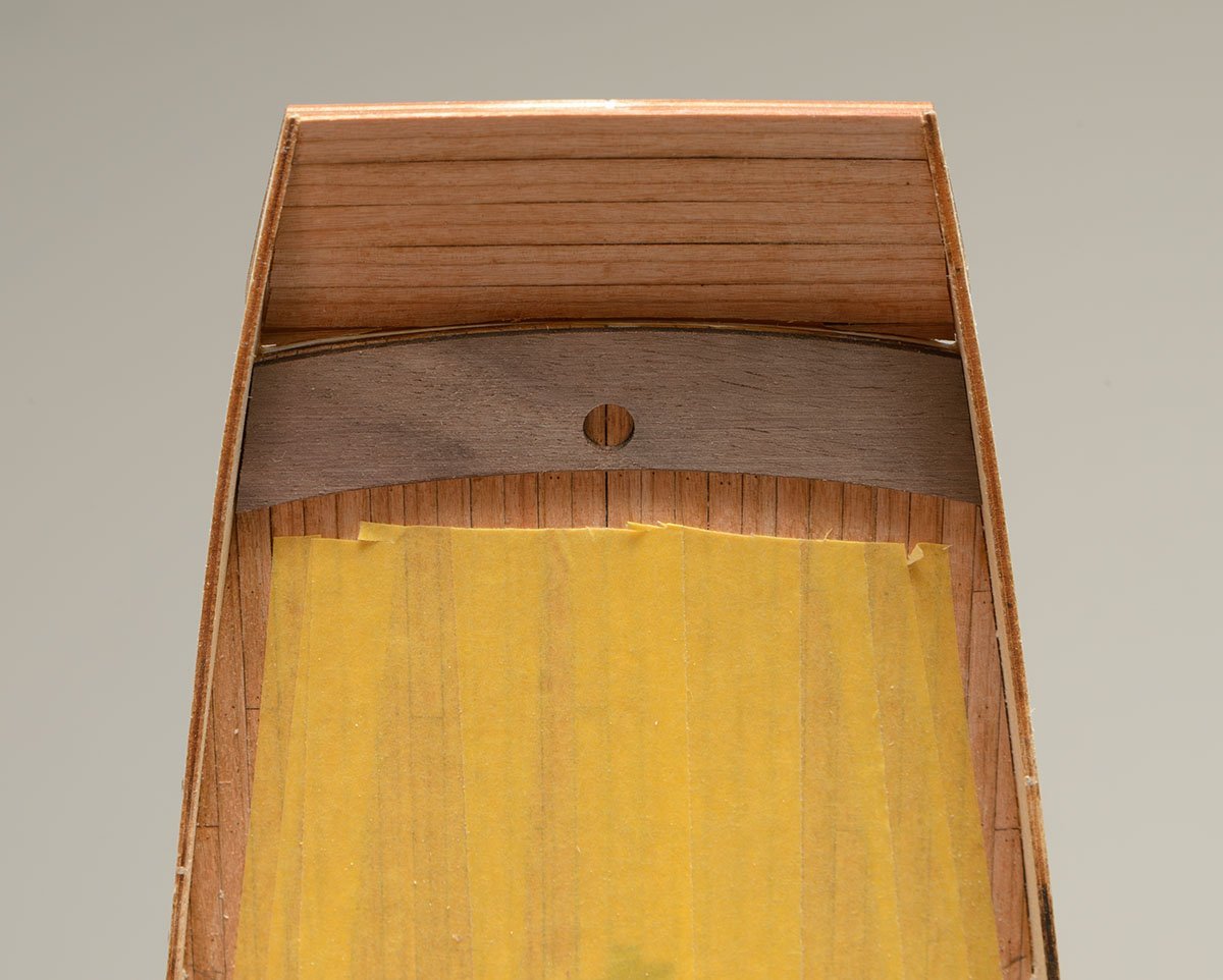
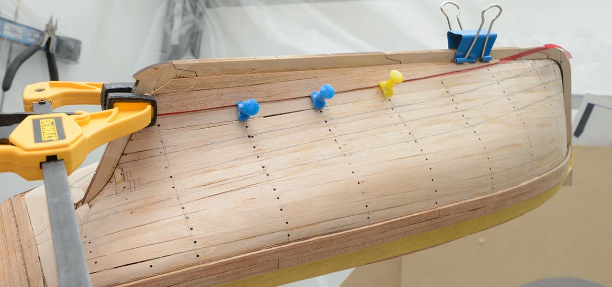
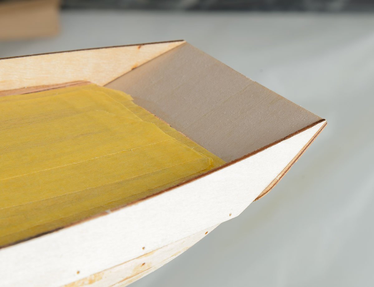
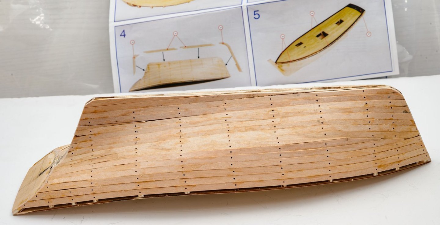
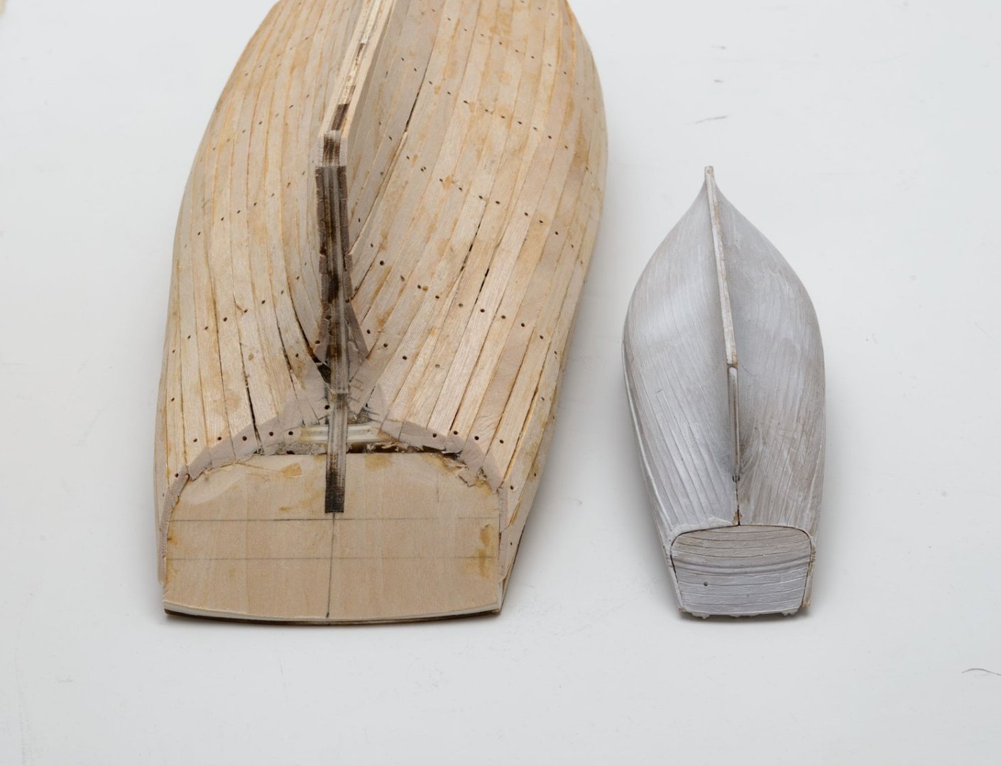
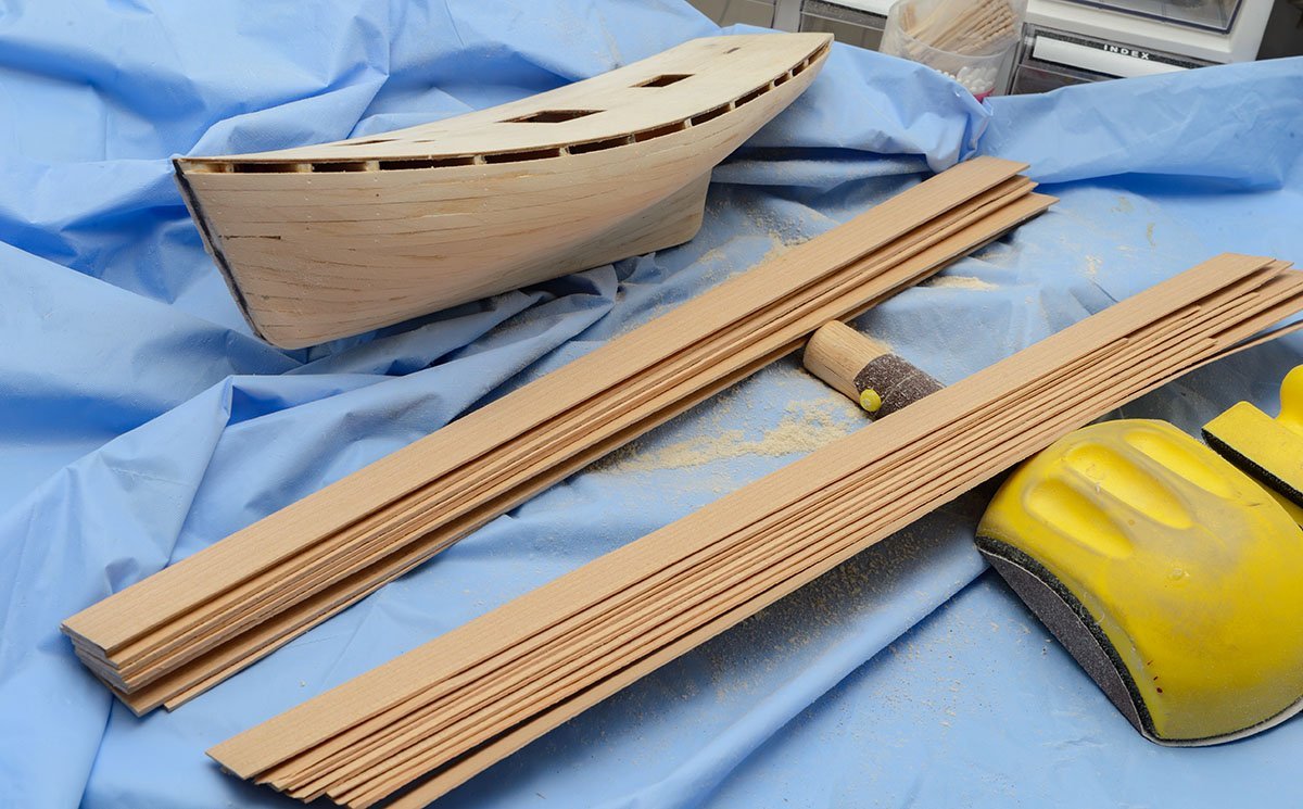
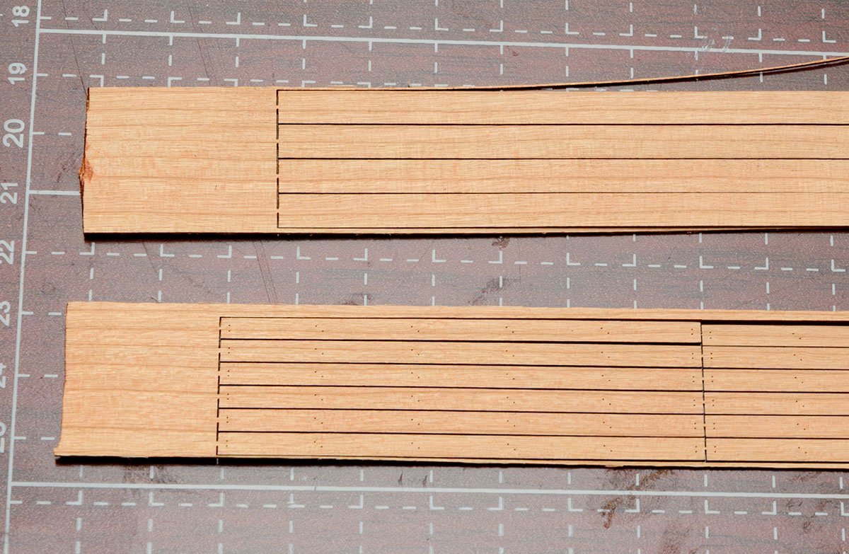
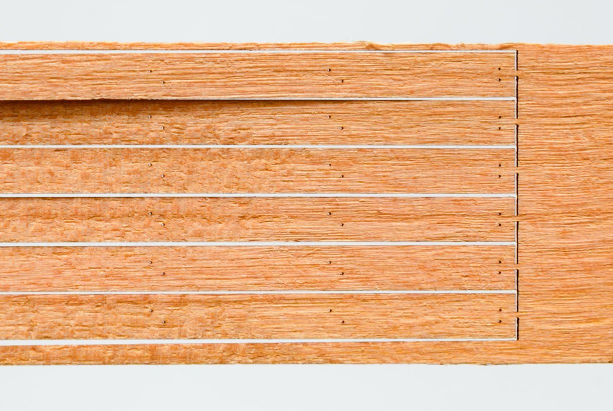
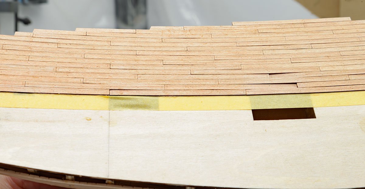
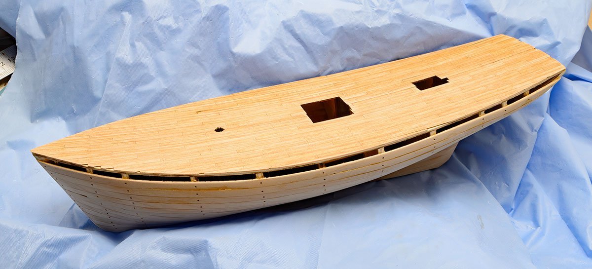
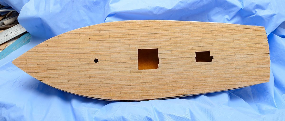
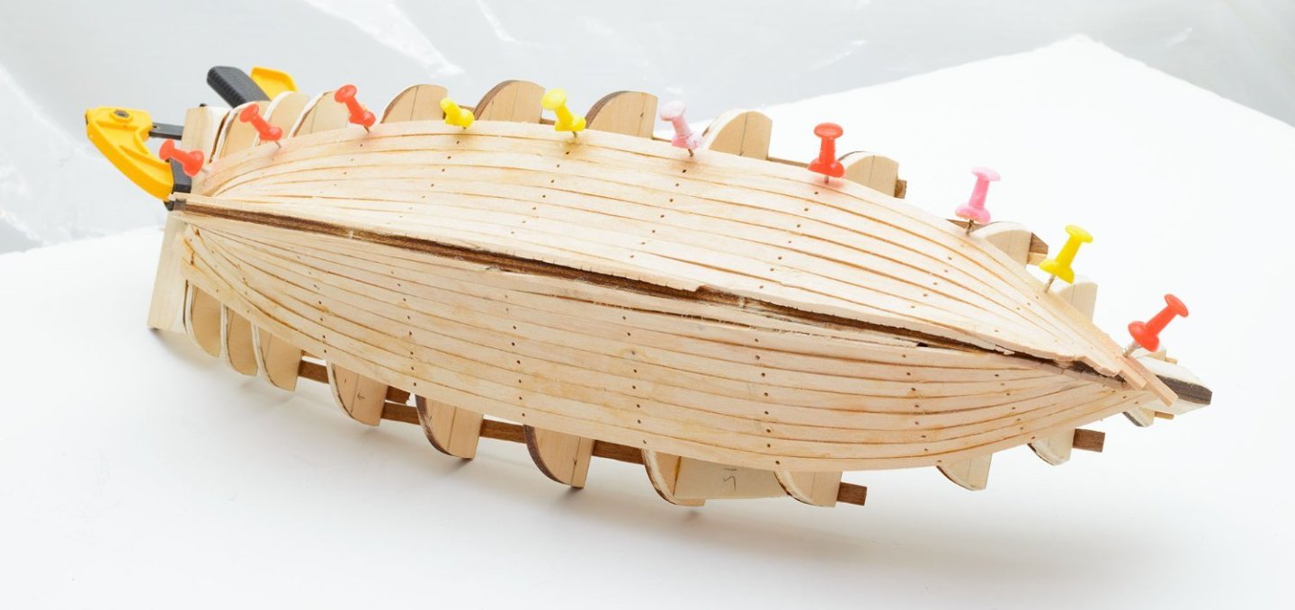
The plastic kit offers better examples than the AotS book. Before I finish the first planking layer, I need some gap for bulwark parts. I placed 3mm thick strips under the deck. The first planking is done. If I follow the manual, I need wood filler and paints. Instead of painting job, I decided to add second planking layer. I made exactly 0.70mm thick cherry sheets. The laser cutter is my best tool. I added nail holes to deck strips. Each hole has a 0.50mm diameter. This was very exciting and rapid progress. Because of the curved deck, it is important to lay each strip one by one. ( I failed last time when I made a larger laser-engraved large sheet.) Another "museum quality." 😆


- 17 replies
-
- 3
-
-
- Marie-Jeanne
- Artesania Latina
- (and 1 more)
-
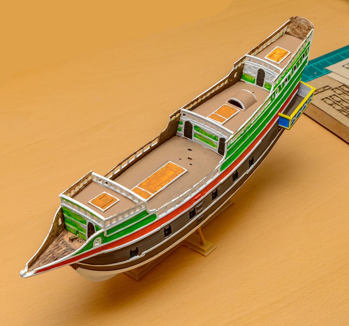
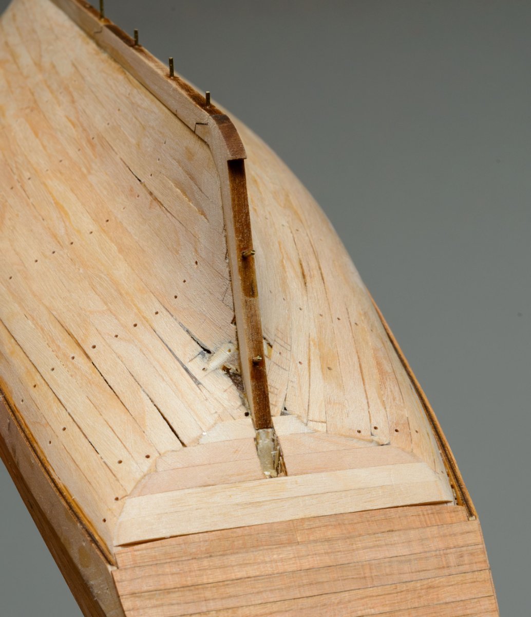
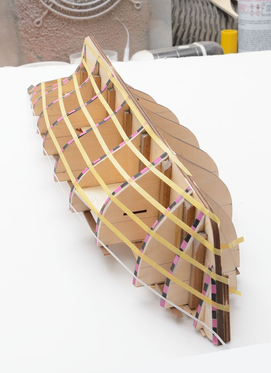
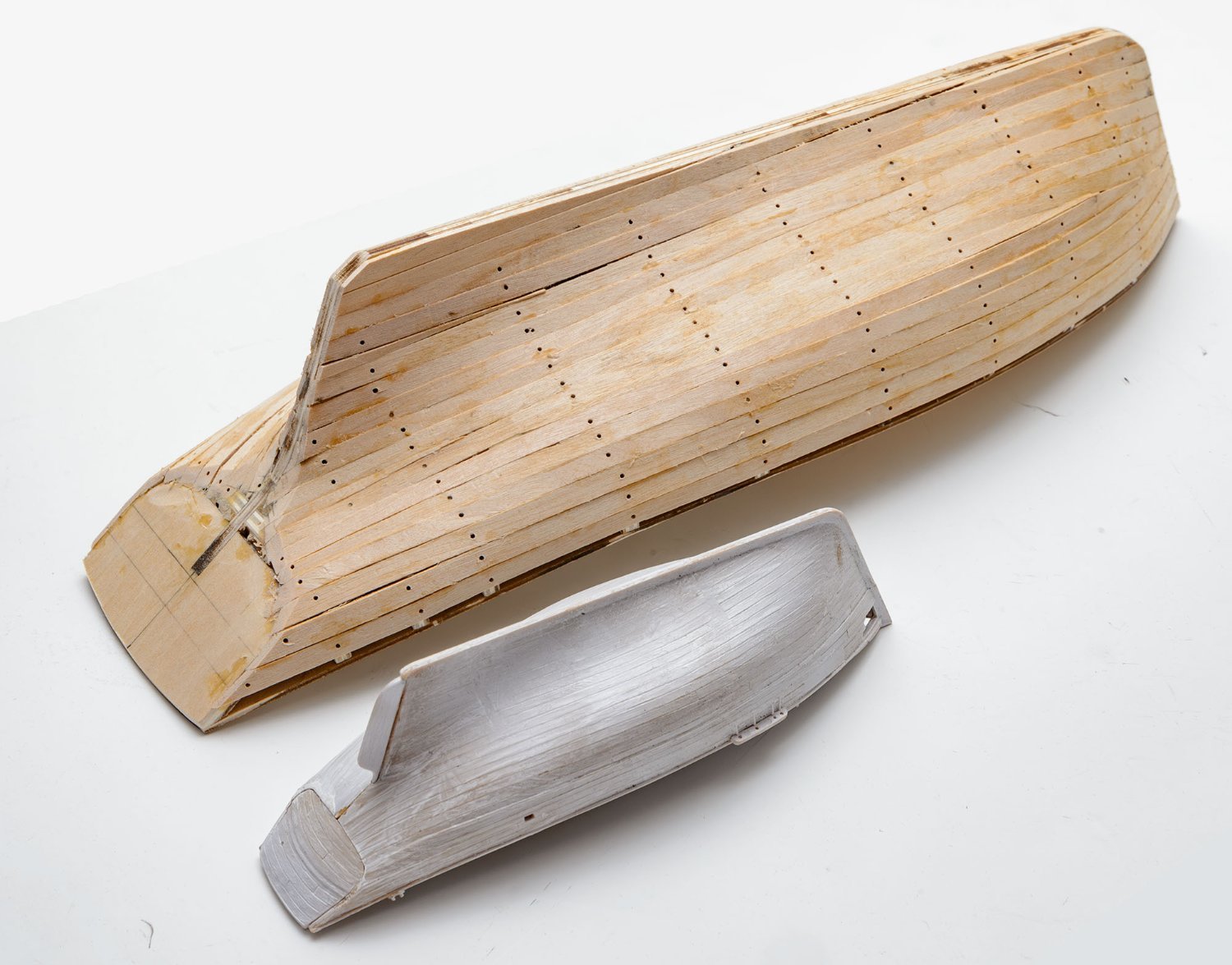
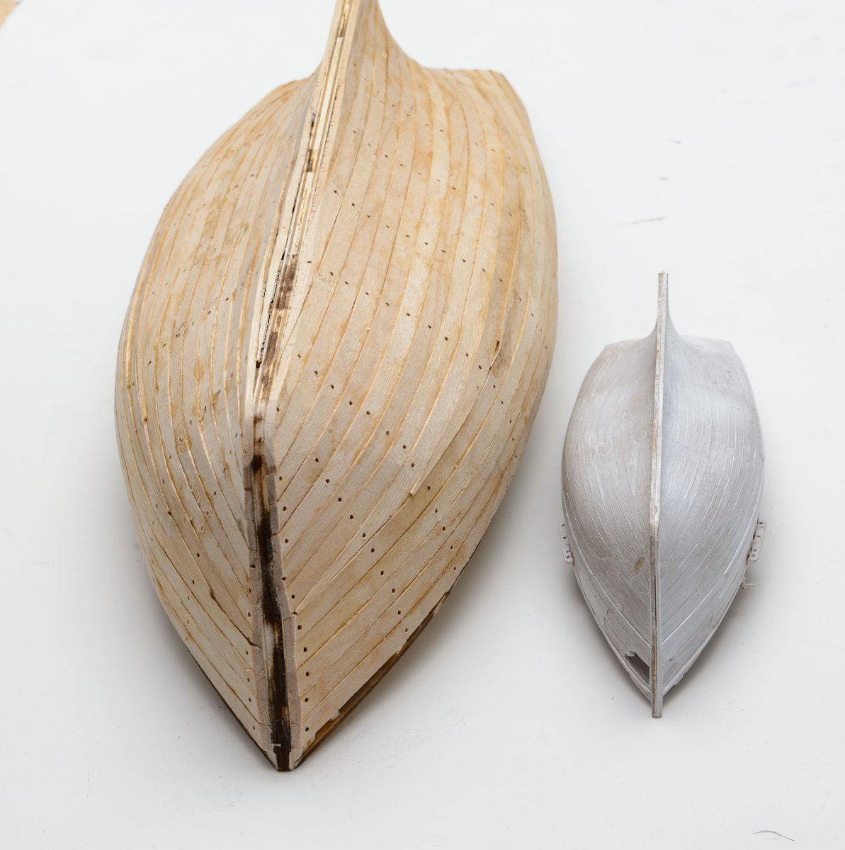
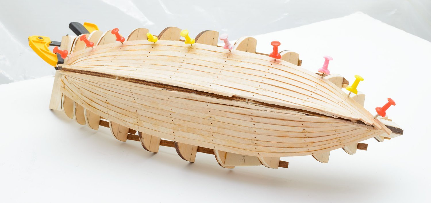
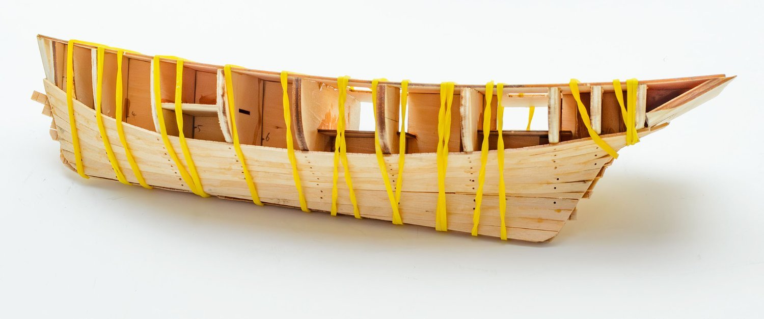
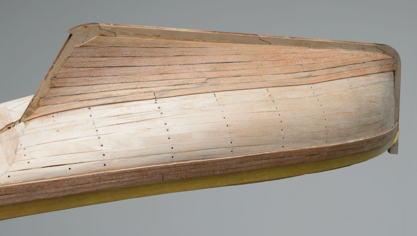
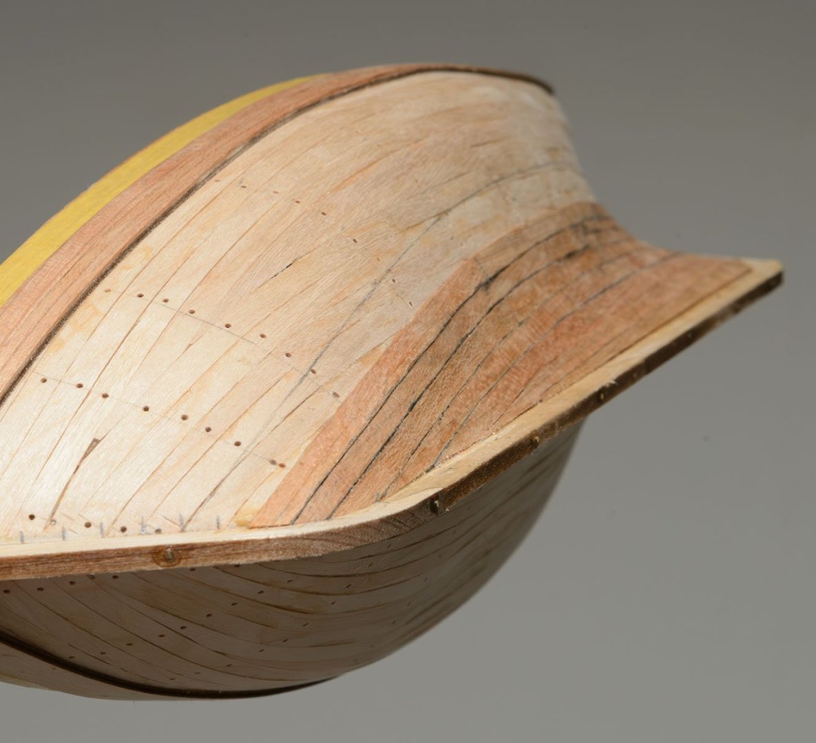
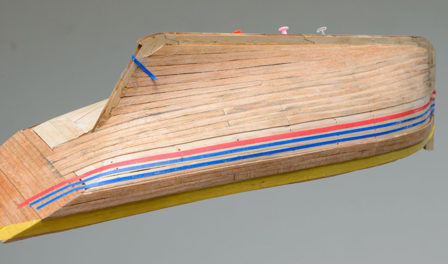
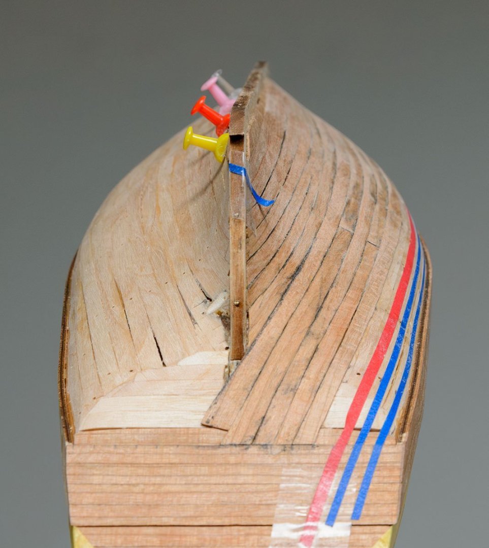
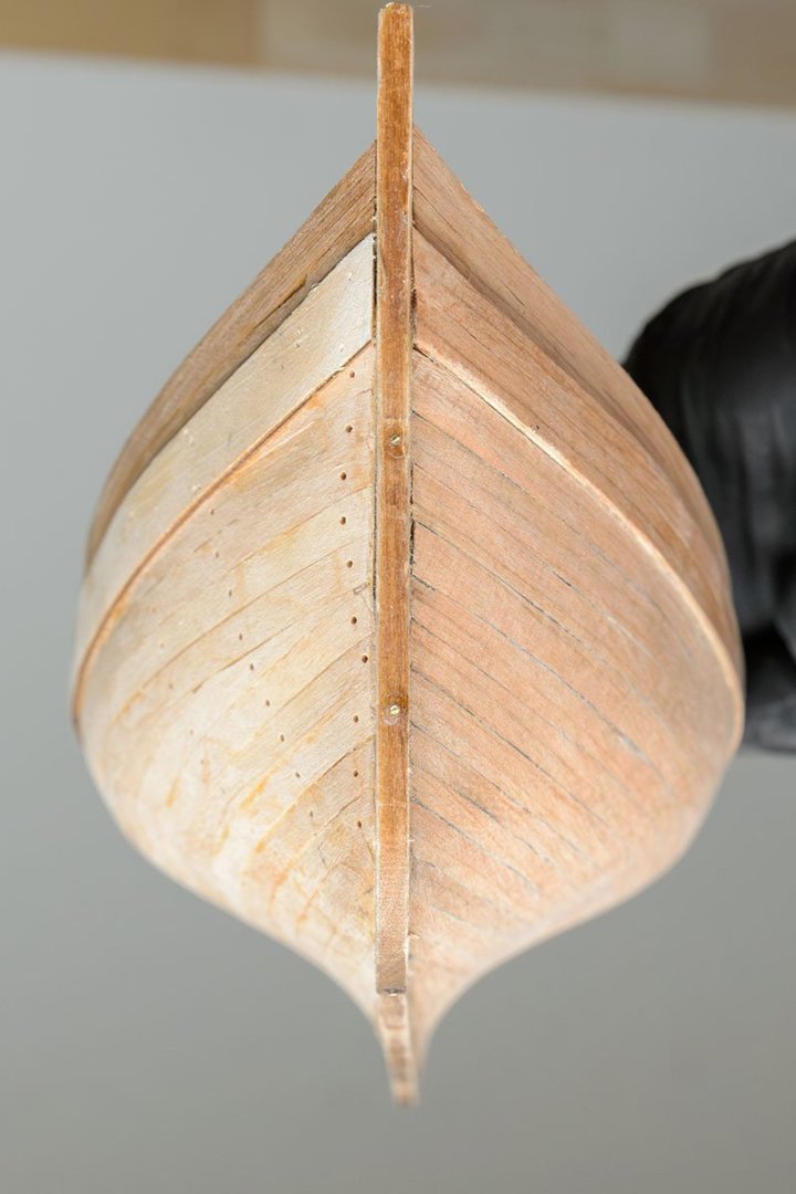
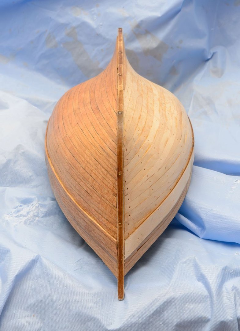
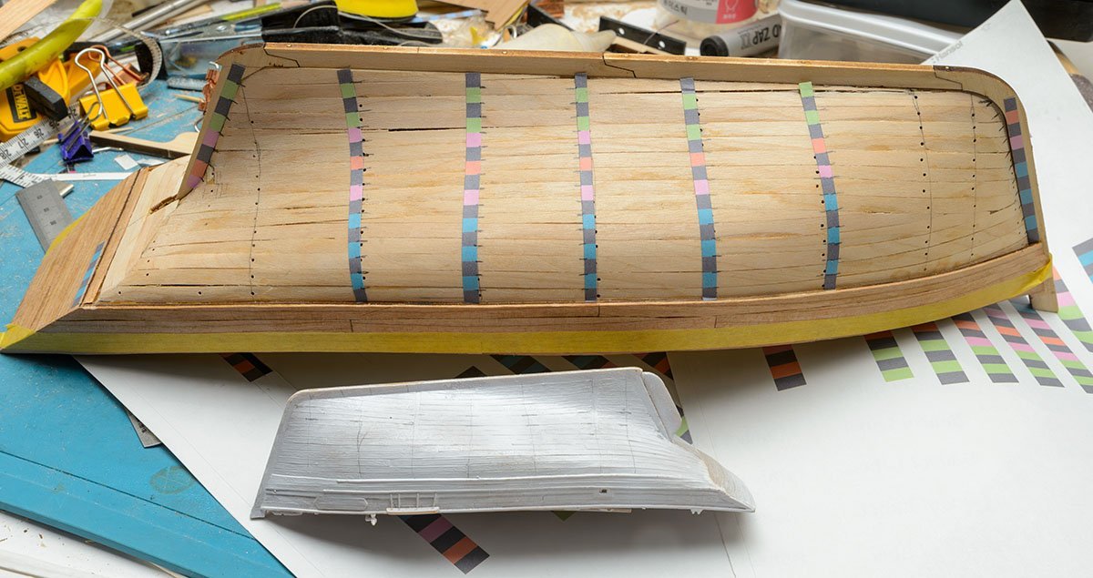
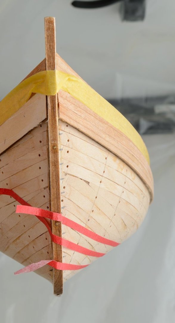
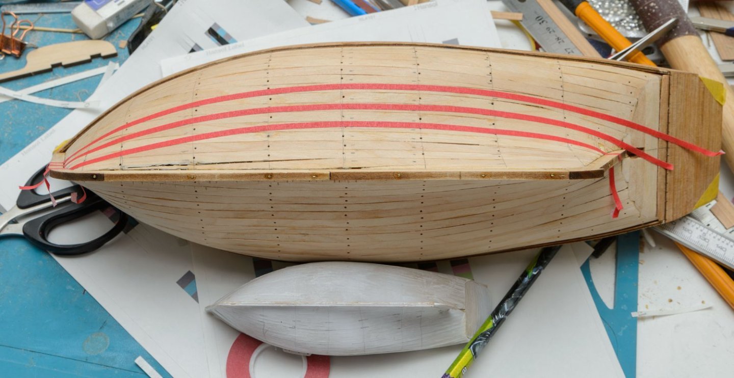
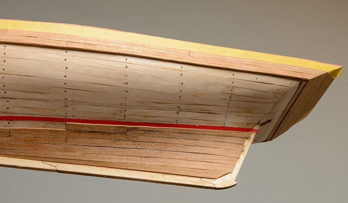
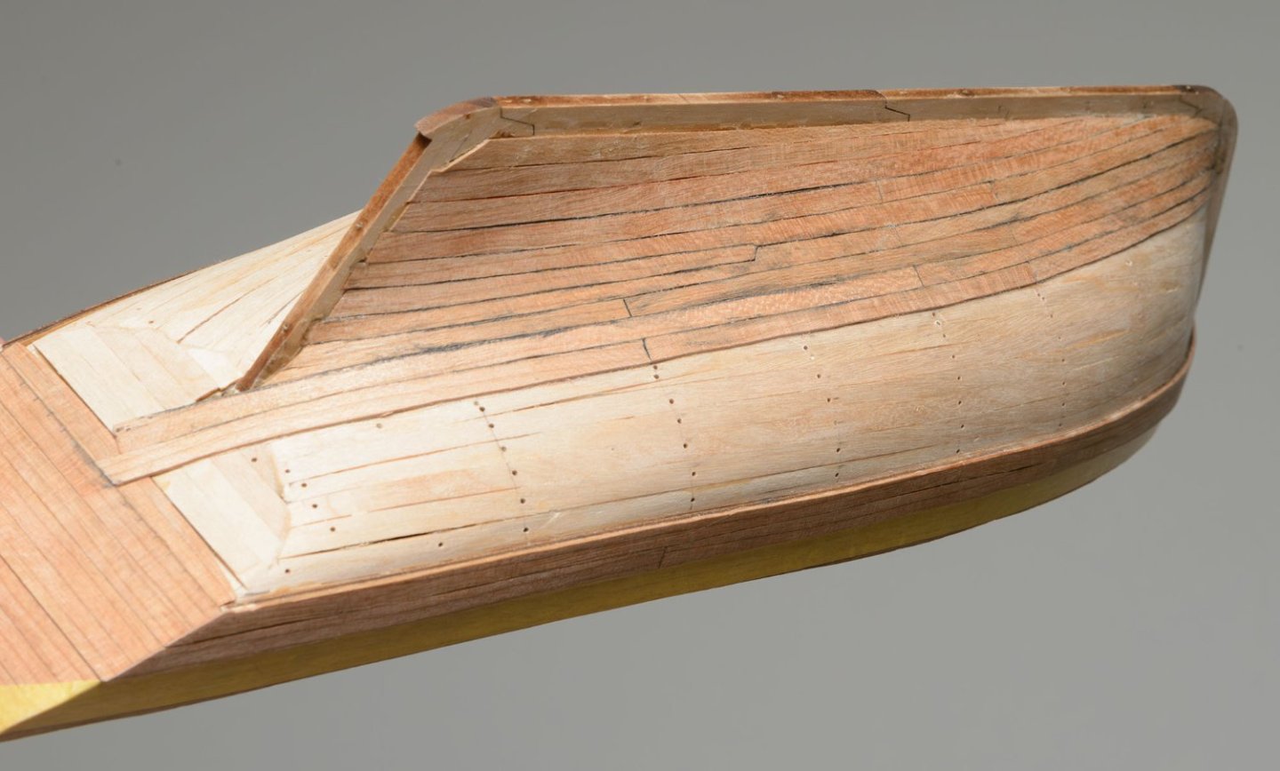
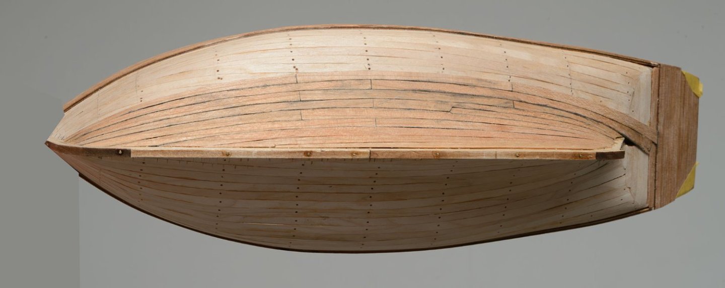
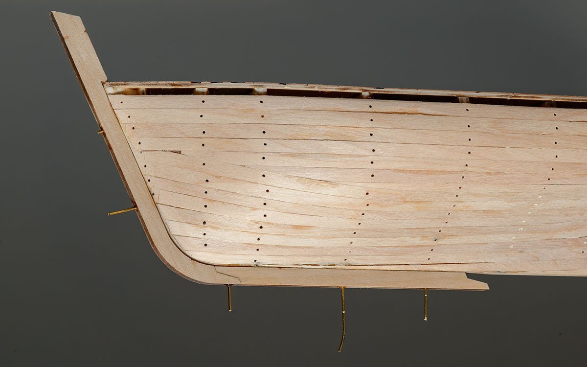
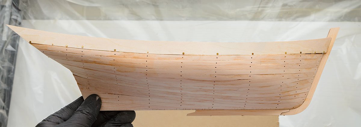
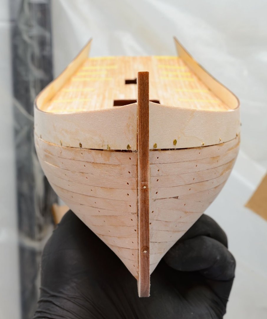
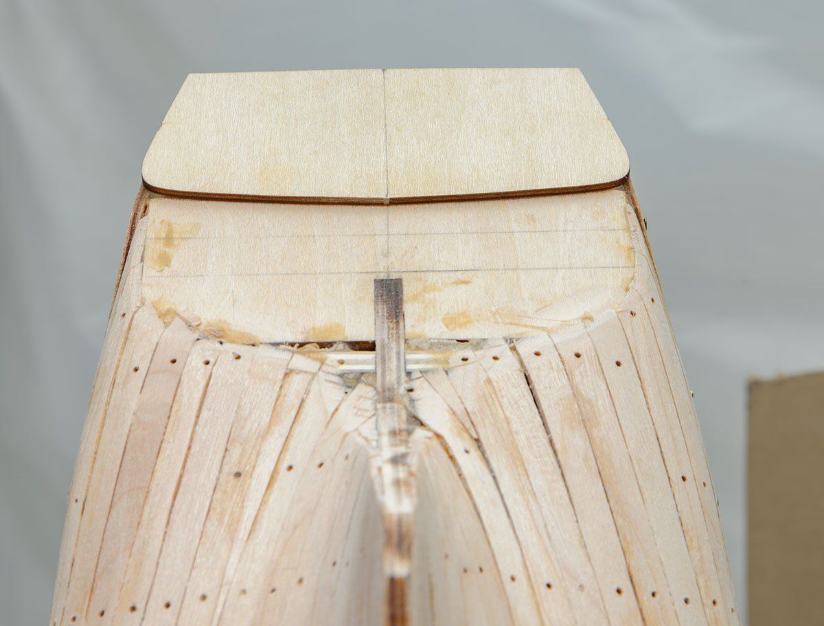
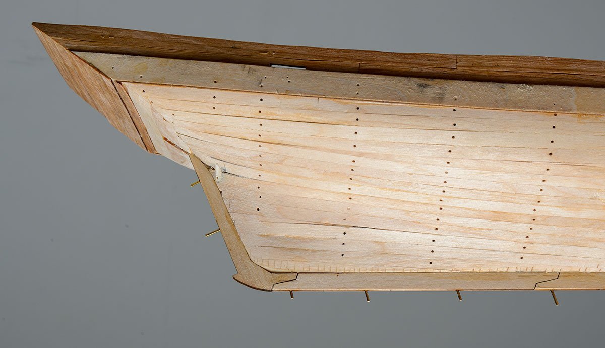
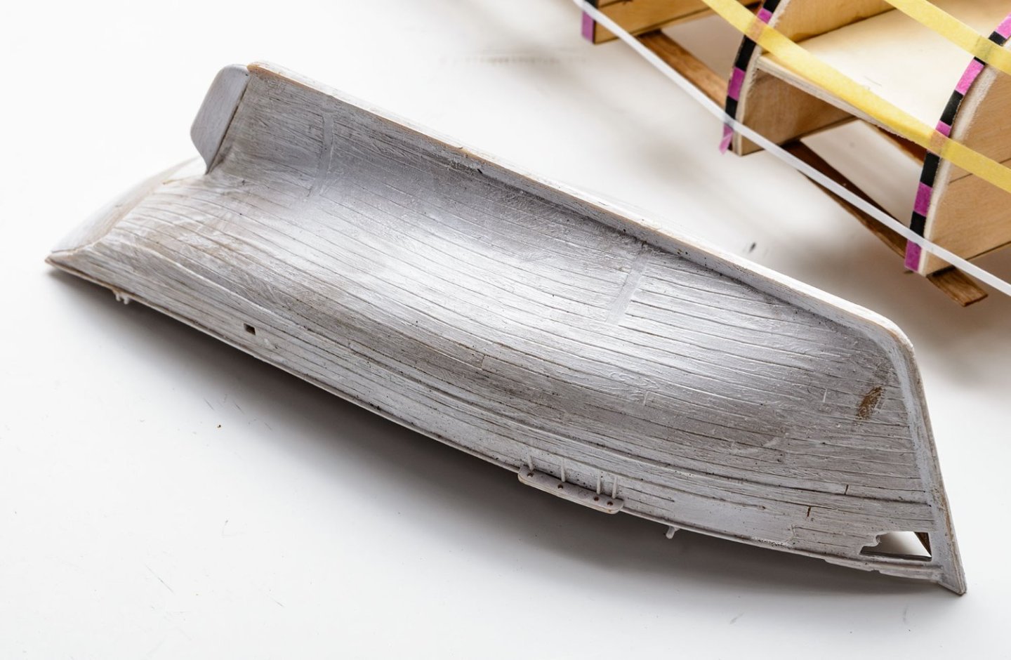
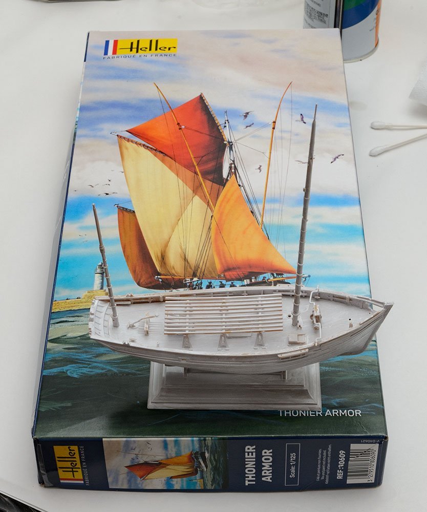
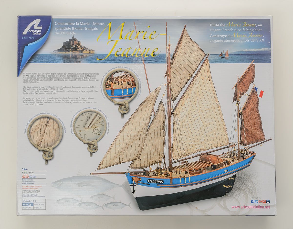
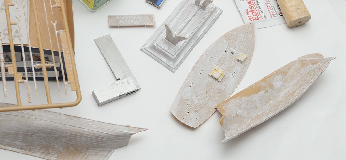
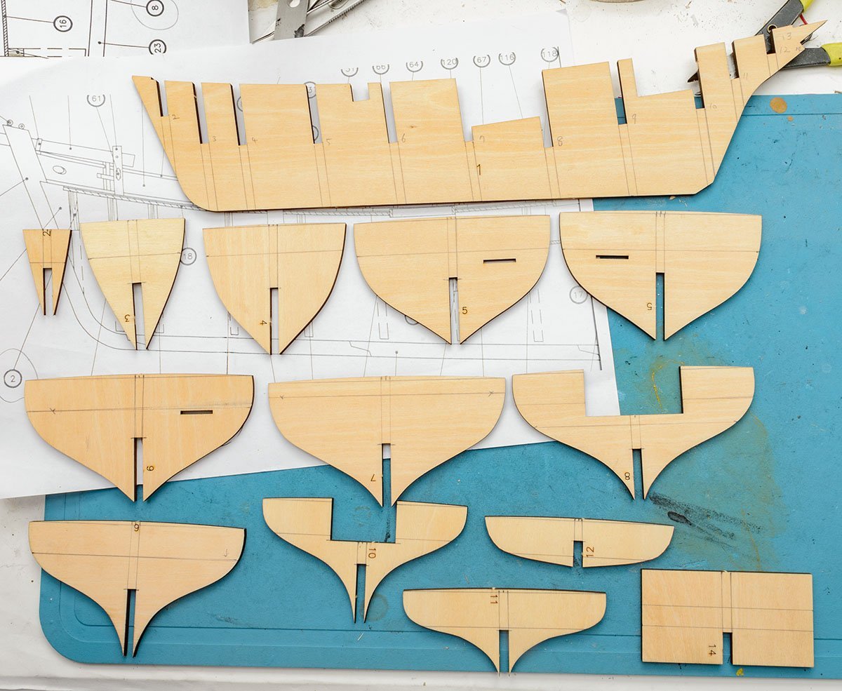
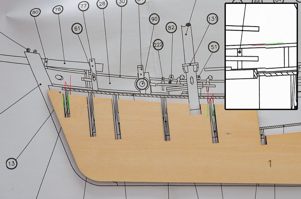
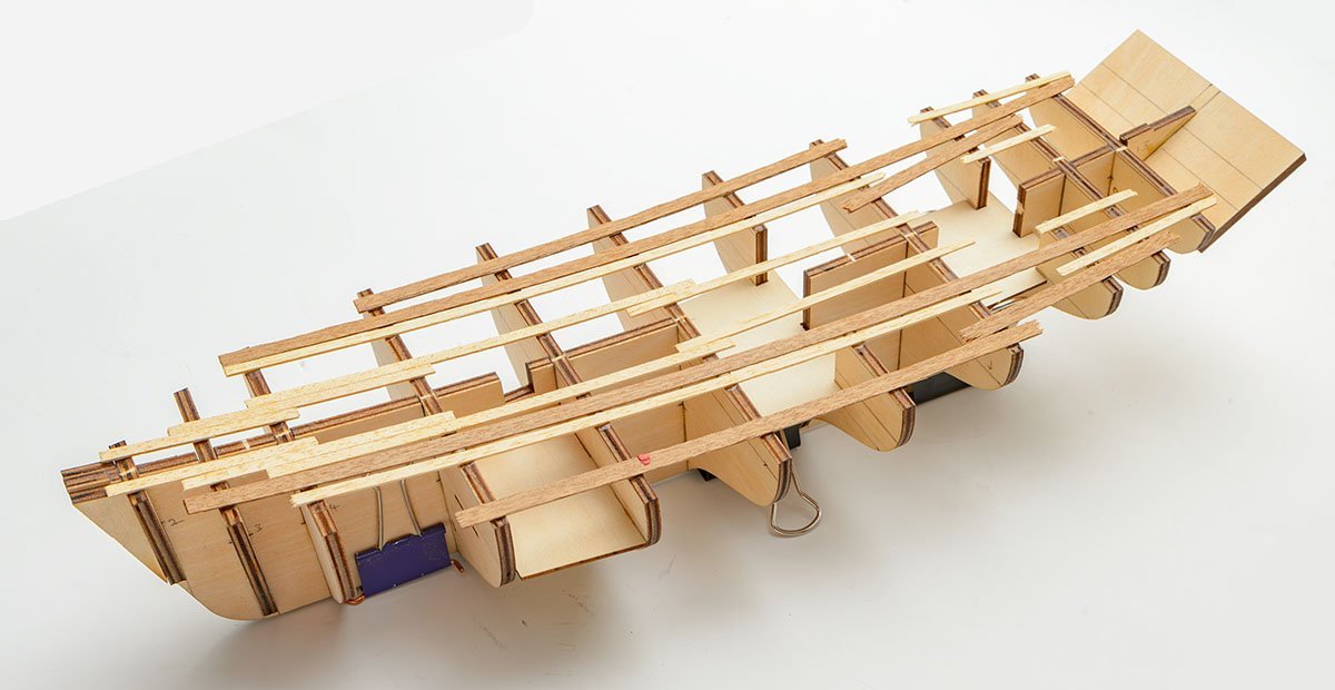
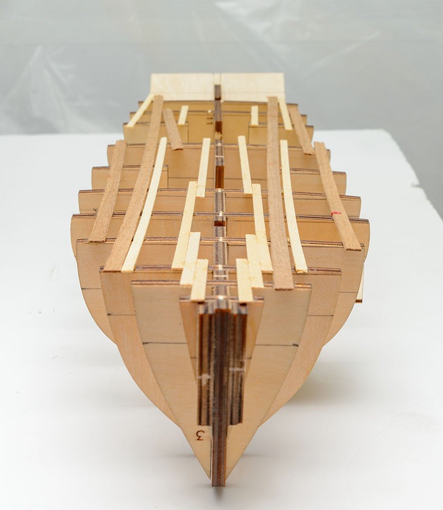
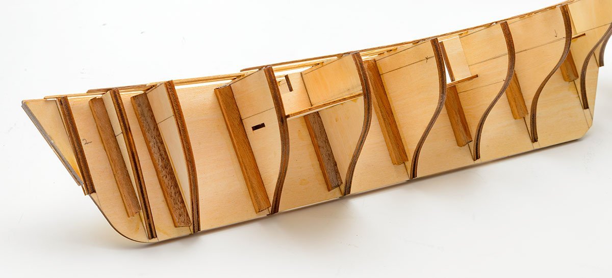
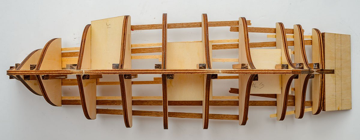
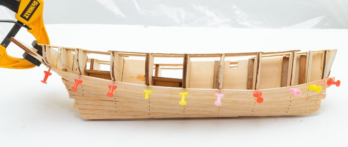
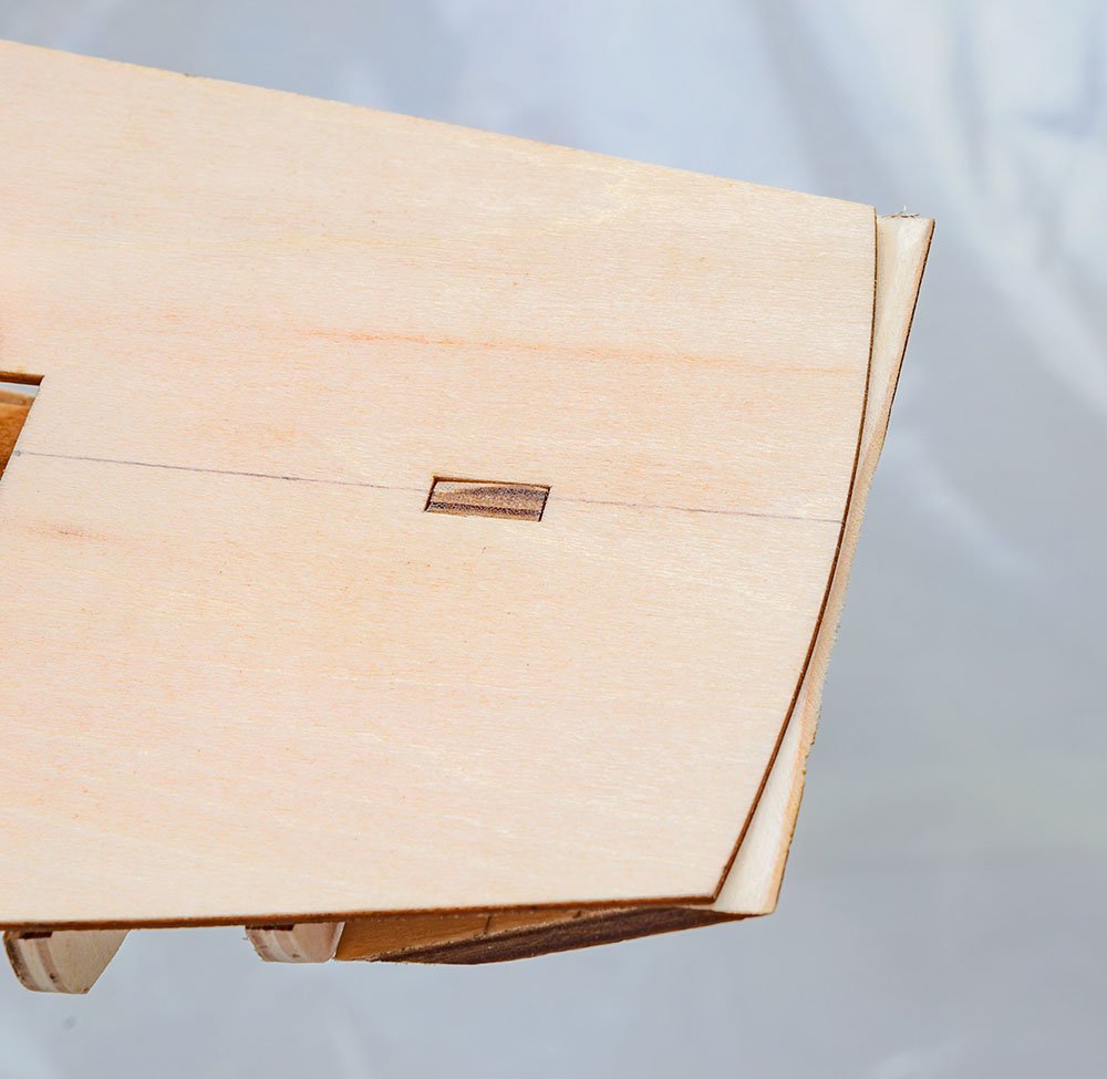
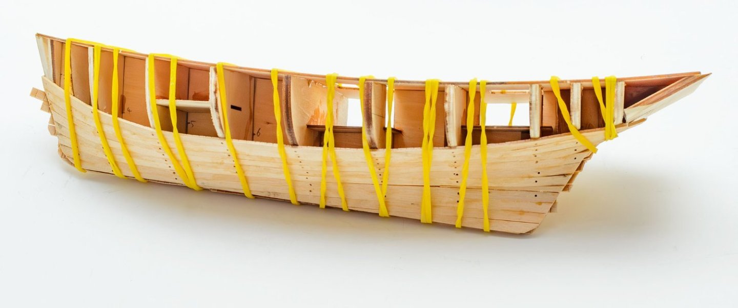
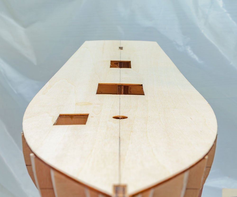
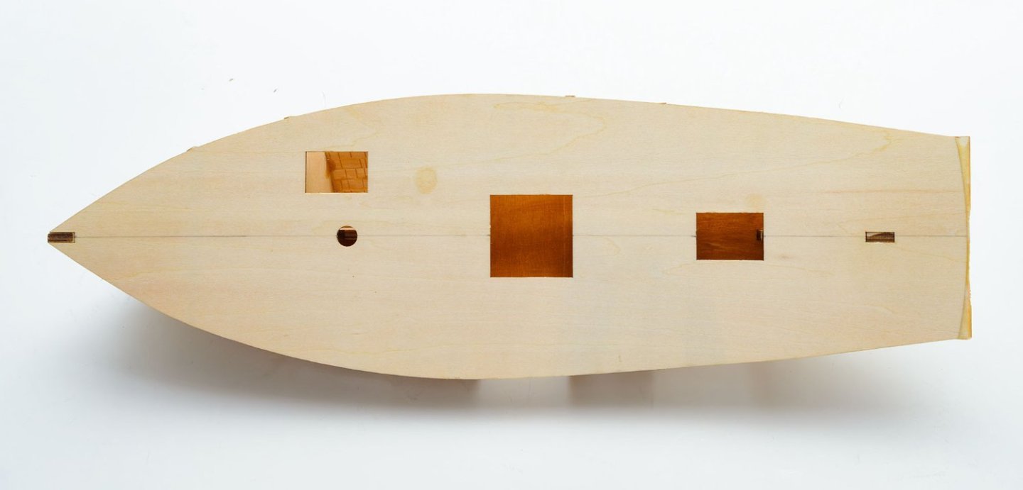
Hello, this is my ongoing project. Dundée Thonier was a type of tuna fishing boat in France during the early to mid-20th centuries. Actually, The AL's thonier Marie-Jeanne wasn't in my interest. I purchased the Heller's thonier Armor because of the beautiful box art. While I was building the plastic kit, I felt limited by the small 1/125 scale. While I was searching reference for the thonier ships, I was surprised that the AL's 1/50 thonier has exactly the same hull as the Heller's. I decided to move to the AL's kit, but the painting will be the same as the Heller's thonier Armor. By the way, my AL kit is outdated 22170. The newer 22175 kit has better box art with clearer instruction. I think AL may need an artist, rather than a photographer. Also, the Heller kit is very helpful, despite its small size. I referenced the hull's planking line. This is my best strategy for framing. I hope kit makers draw the check lines on frame parts. The AL's old kits tend to offer unreliable manuals and plans. As you see, the 1:1 plan paper didn't match with the kit's parts. Those small differences come together and form an ugly, twisted hull. I made an effort to build straight hulls against the pervasive issues. The check lines on frame parts are my best solution, for now. Instead of laying a deck sheet, I used many short temporary batterns. I was able to set an accurate distance between frames, and the batterns offered better sight. * I recommend using hardwood-dark strips, such as walnut. The basswood-white strips are too weak for use of temporary battern. These square bars help to hold frames. The first planking was easy and smooth. After I filled half of the first planking layer, I removed the temporary batterns and placed a deck sheet. There is one more error. As you see, the deck didn't fit the hull tightly. I needed a day to fix the problems. The result is extremly, enormously, gorgeously fine. It is the first hull I've ever made that didn't twist in any direction. In other words, "museum quality."
- 17 replies
-
- 5
-
-
- Marie-Jeanne
- Artesania Latina
- (and 1 more)
-
I guess this kit is from the Russian kits by DeAgostini.ru. The company launched similar kits earlier than AL. It may explain why the recent AL kits are superior to the old kits. The DeAgostini sells magazine subscription kits, like the Hachette. The total price is higher than AL, and the Russian magazines are not available in many regions. I'm interested in Le Soleil Royal, which is also shown on the DA site.
-
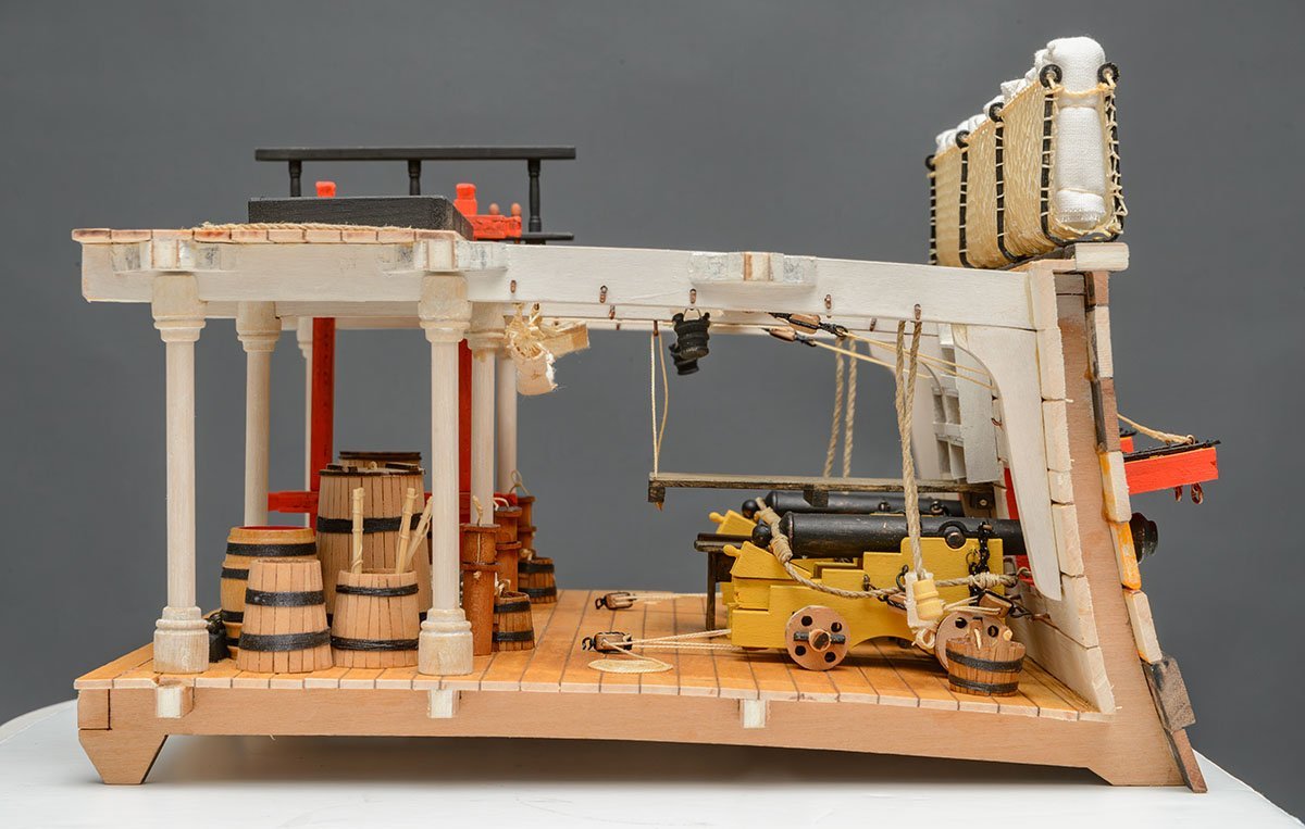
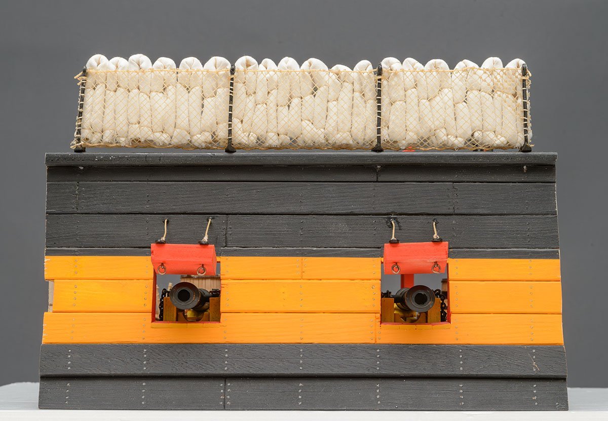
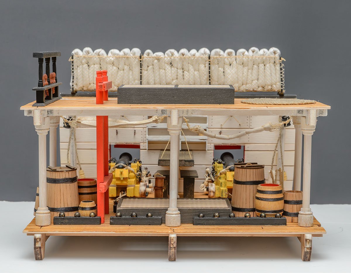
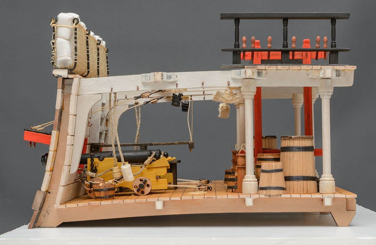
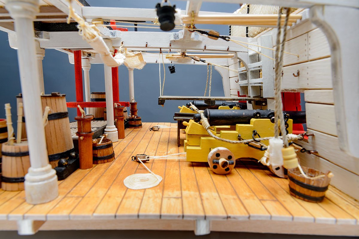
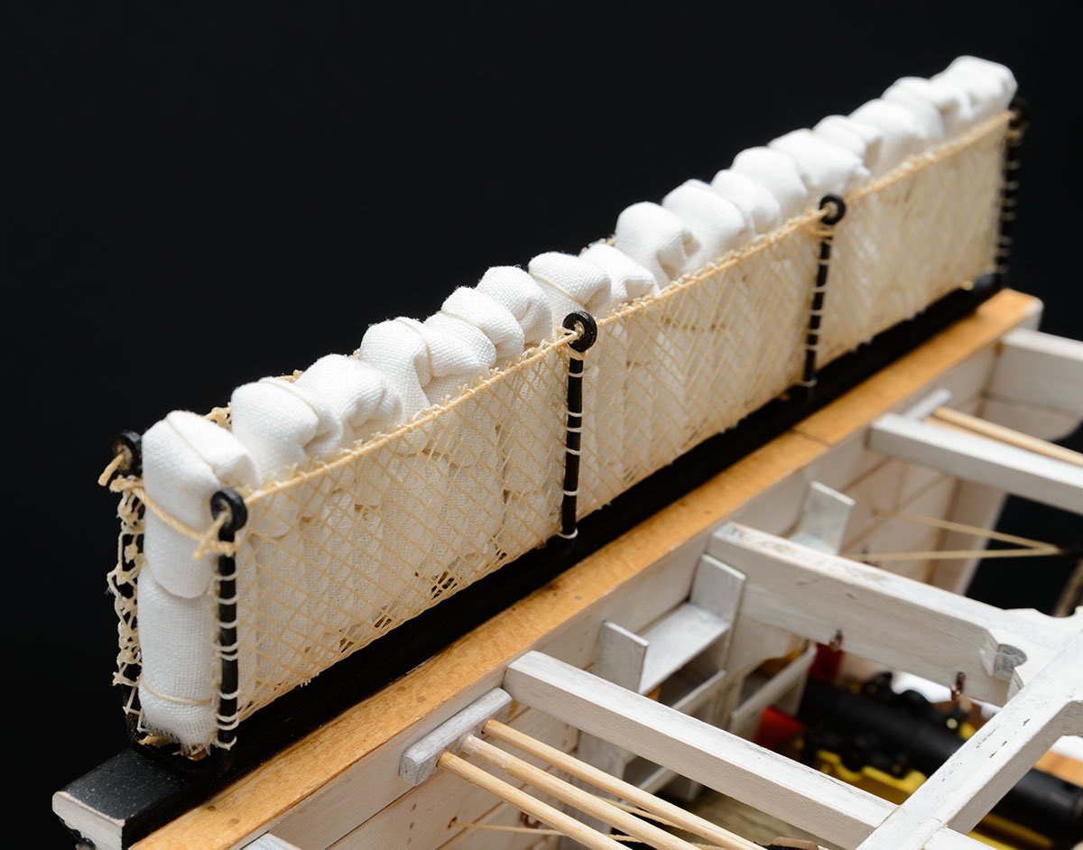
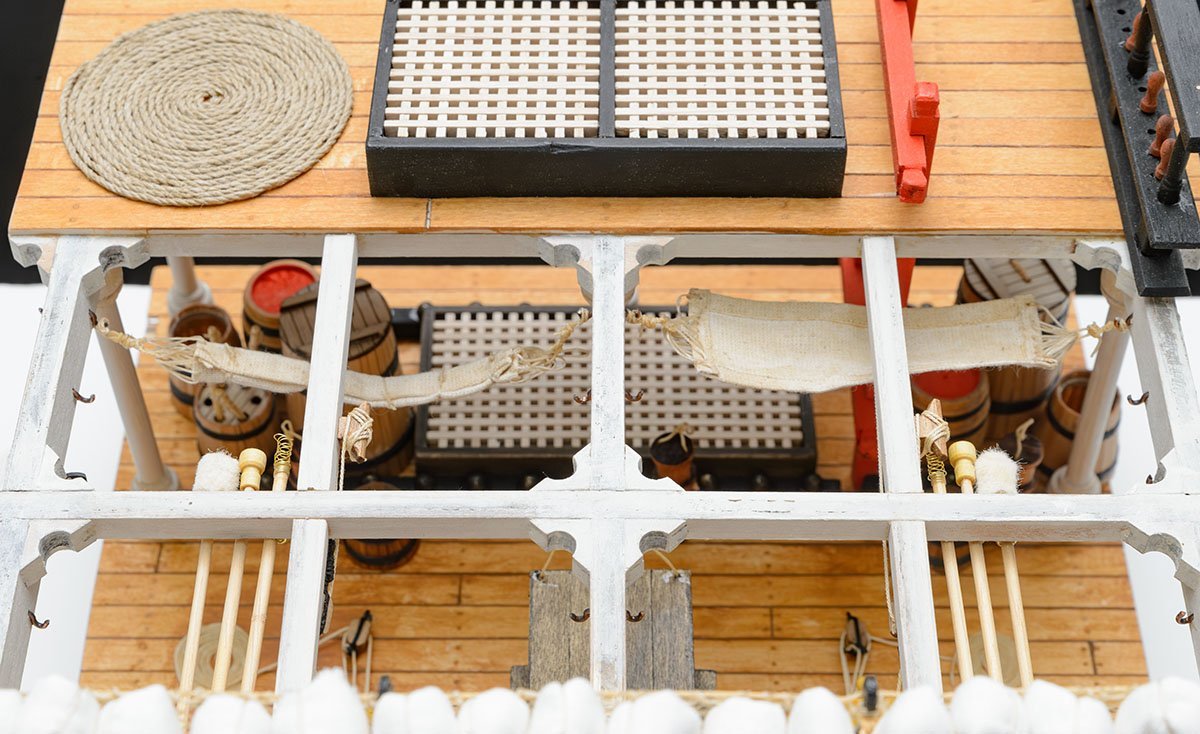
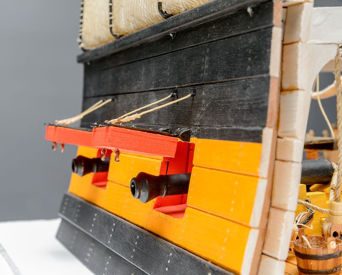
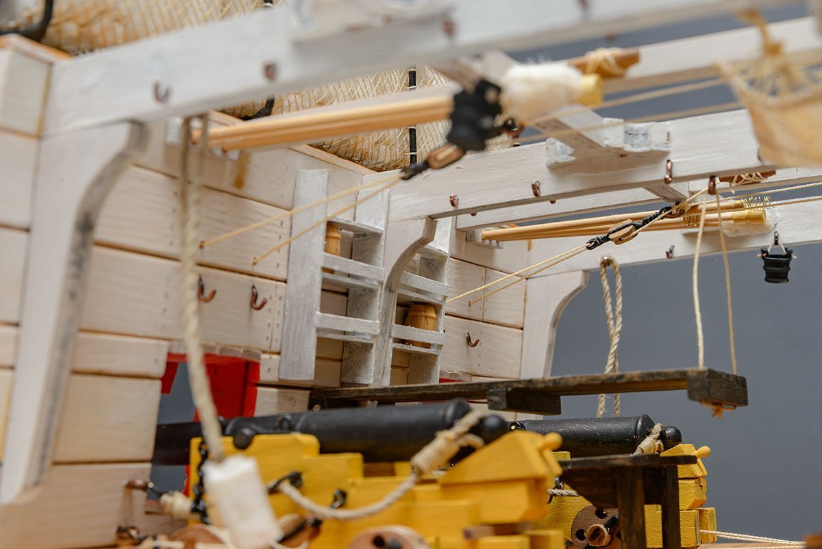
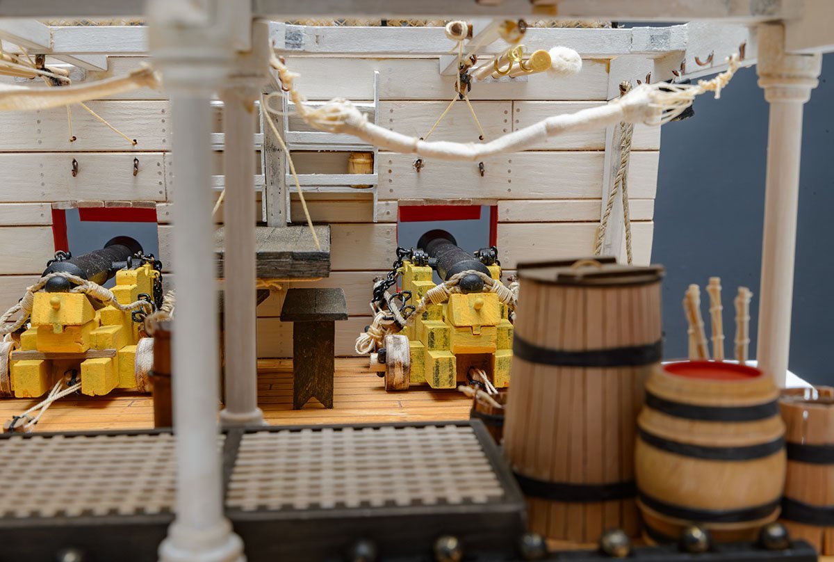
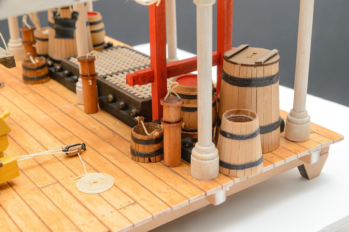
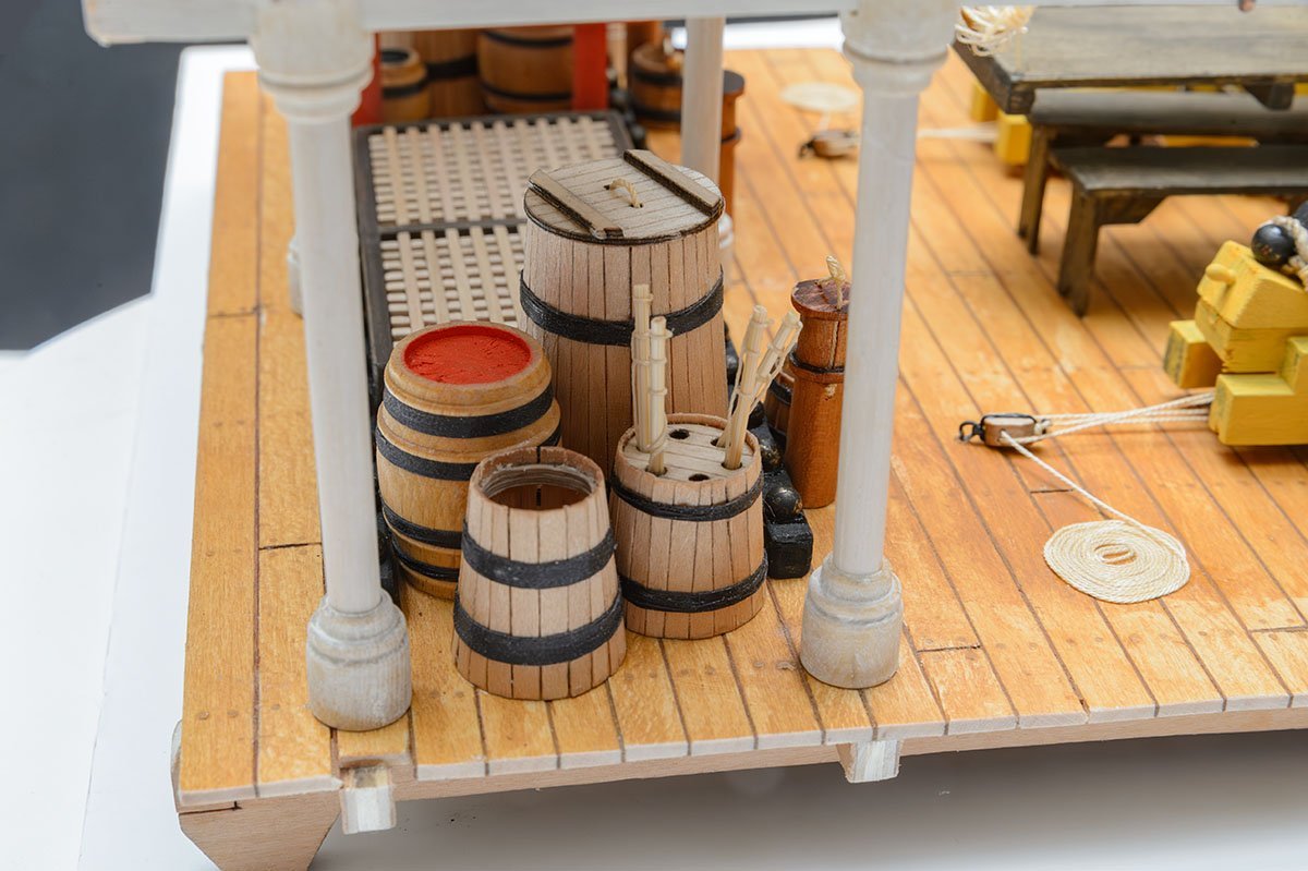
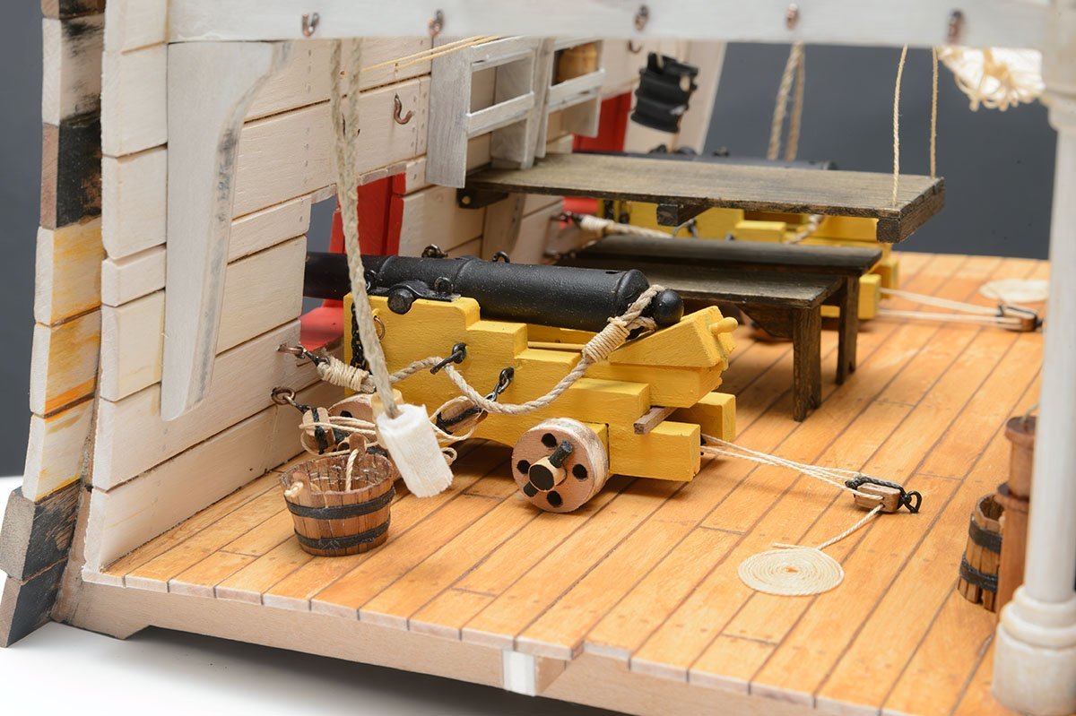
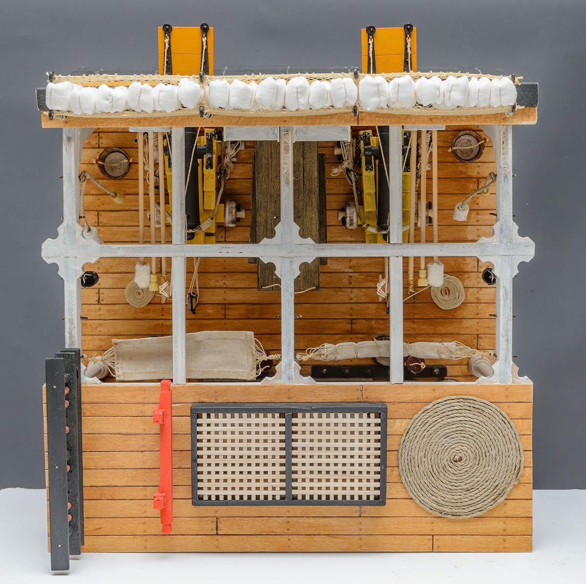
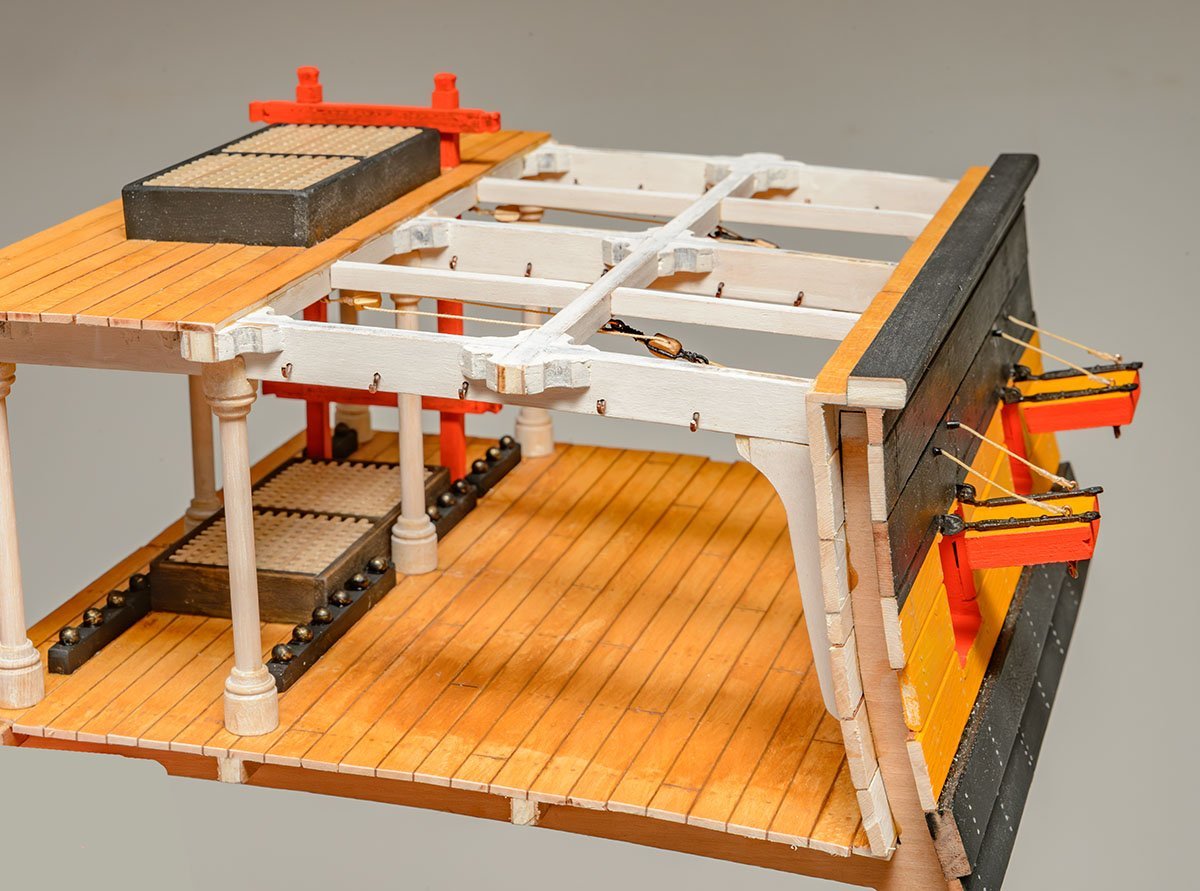
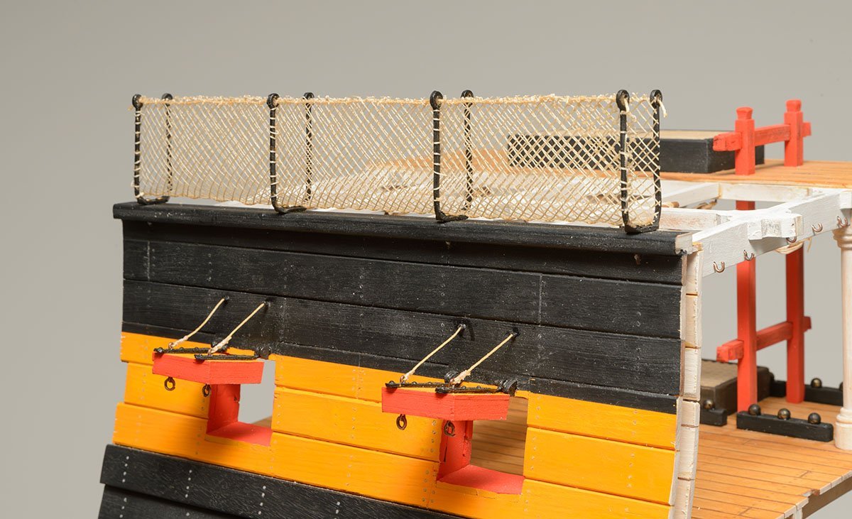
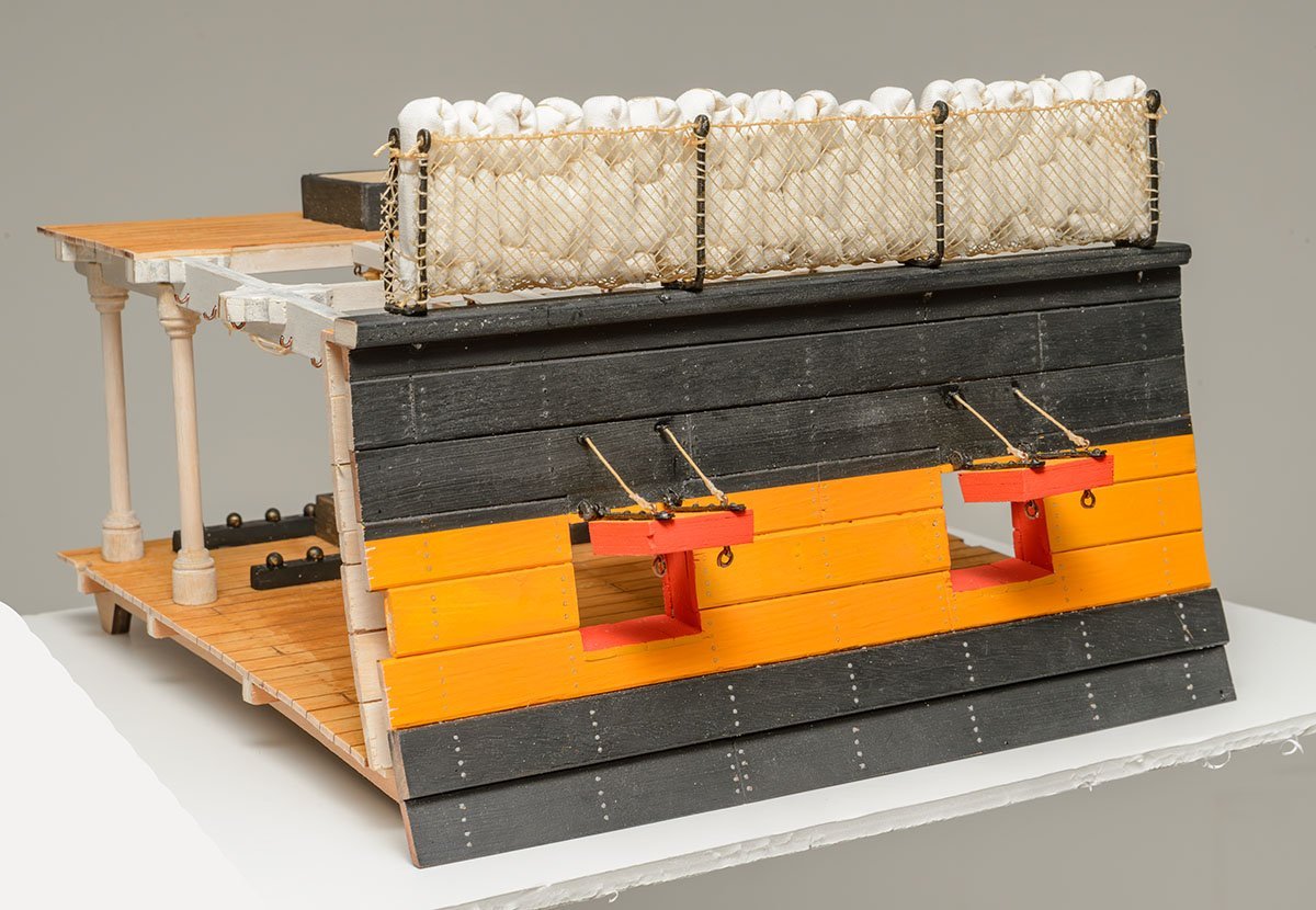
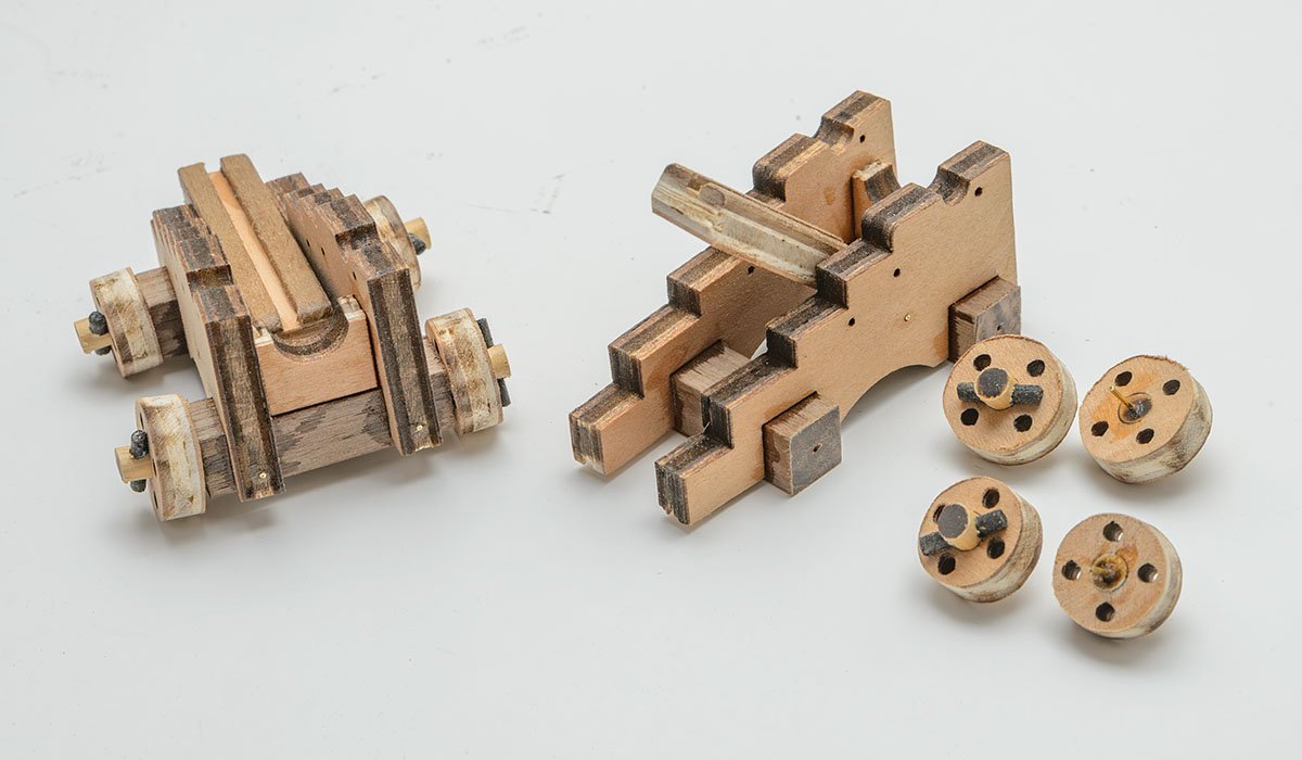
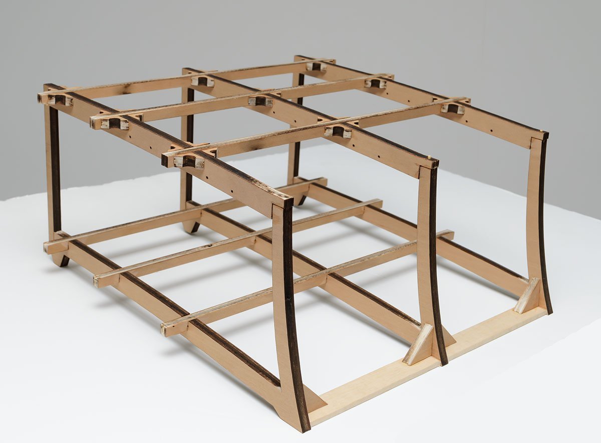
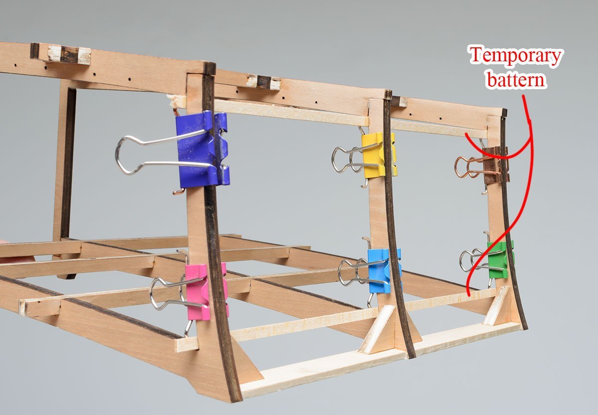
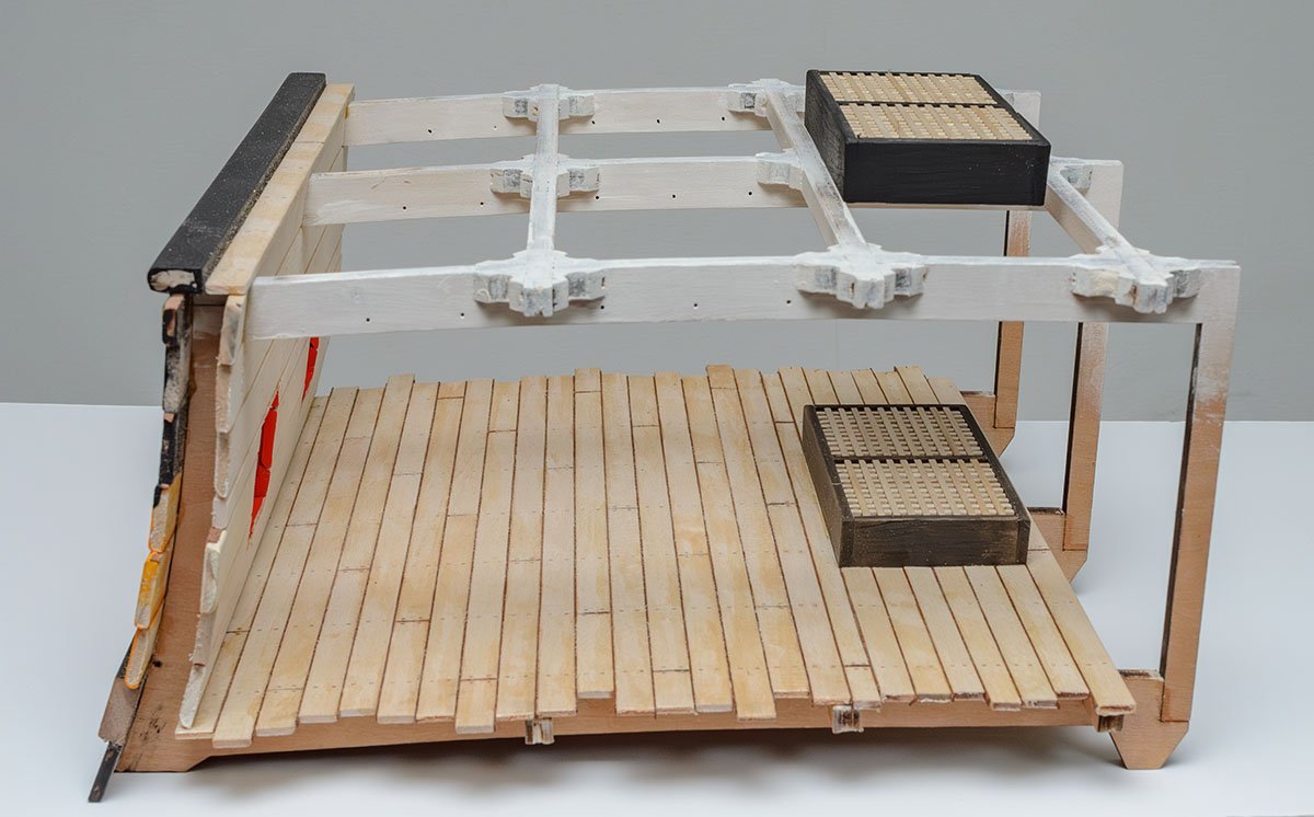
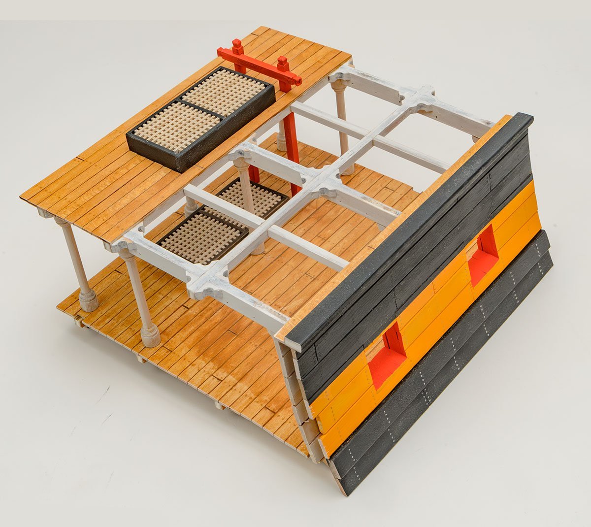
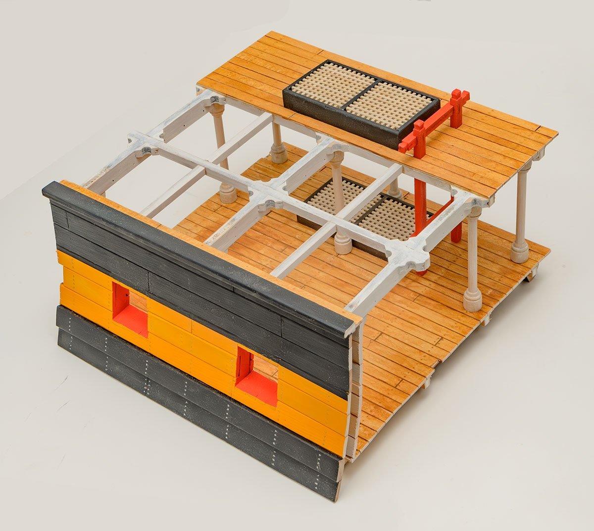
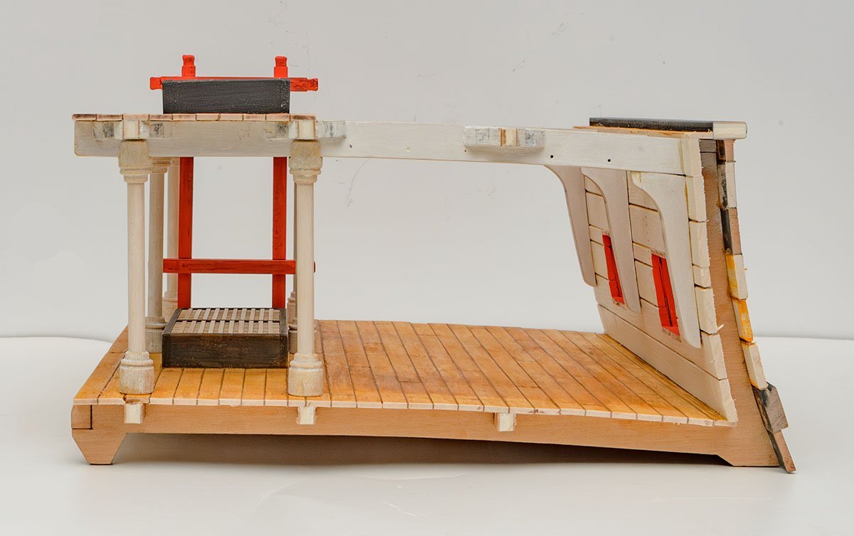
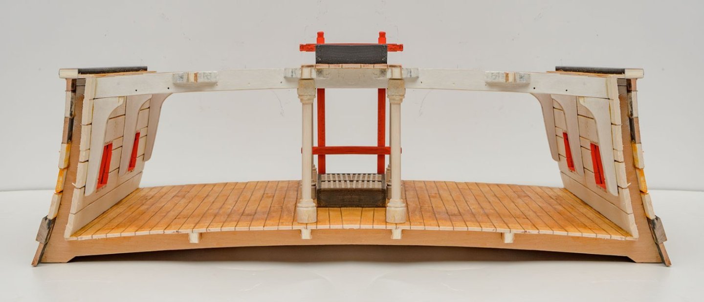
Mine is based on the HMS Victory. I referred to tour videos on Youtube. Thanks to everyone for watching my build log~
- 8 replies
-
- 2
-
-
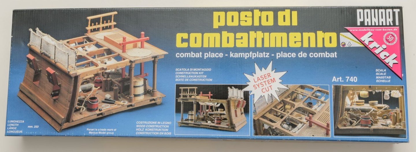
- combat place
- Panart
- (and 2 more)
-
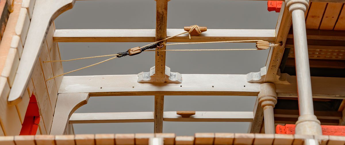
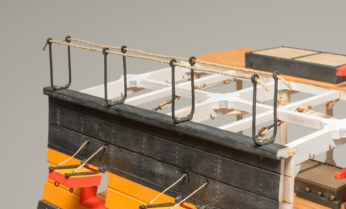
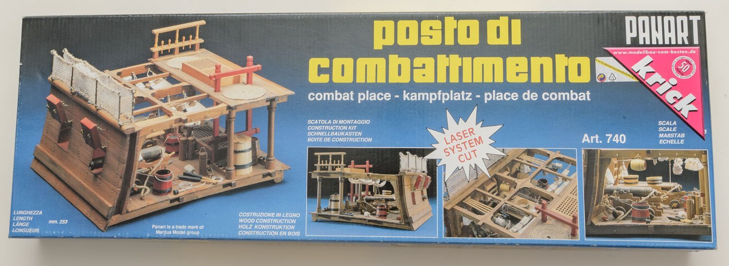
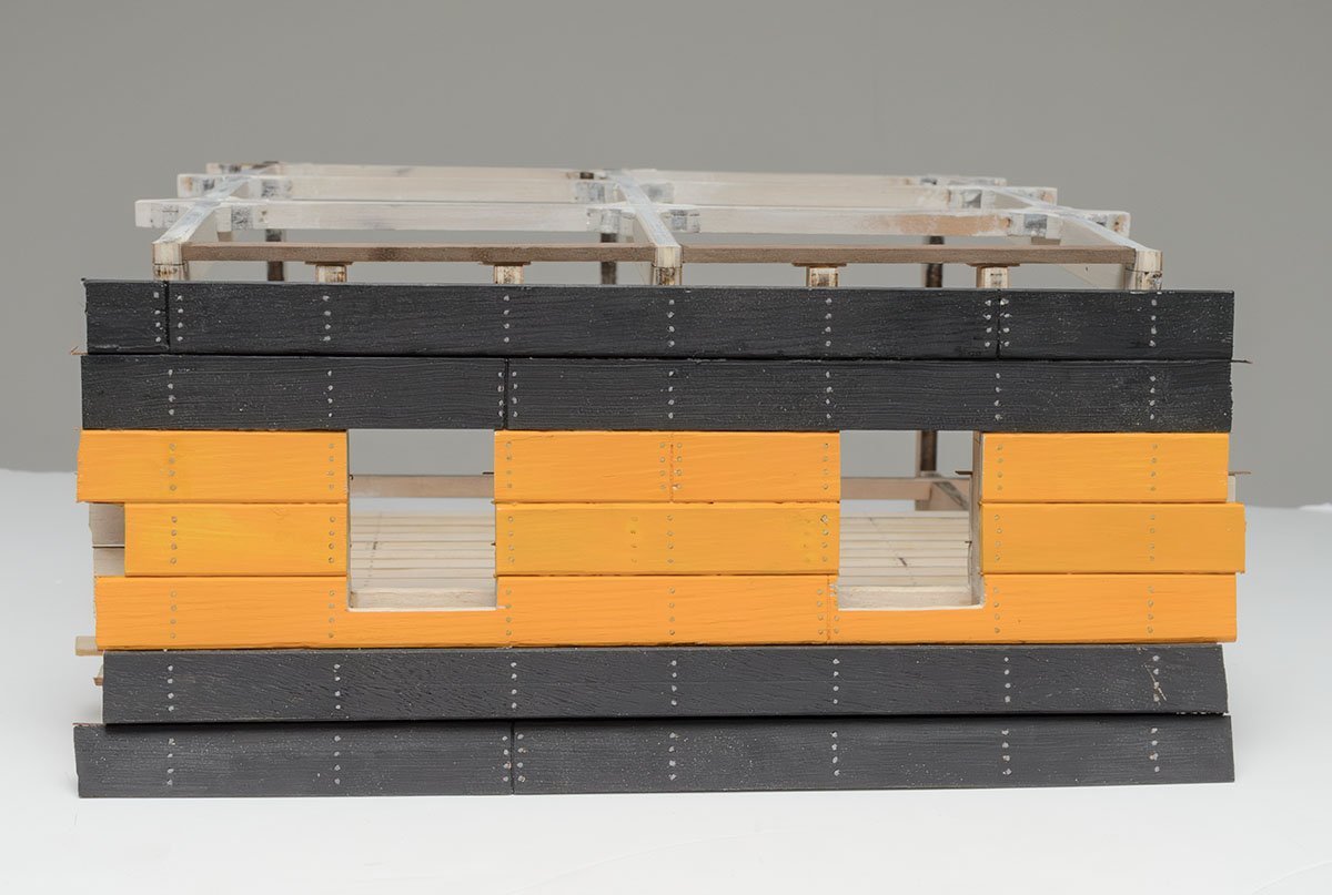
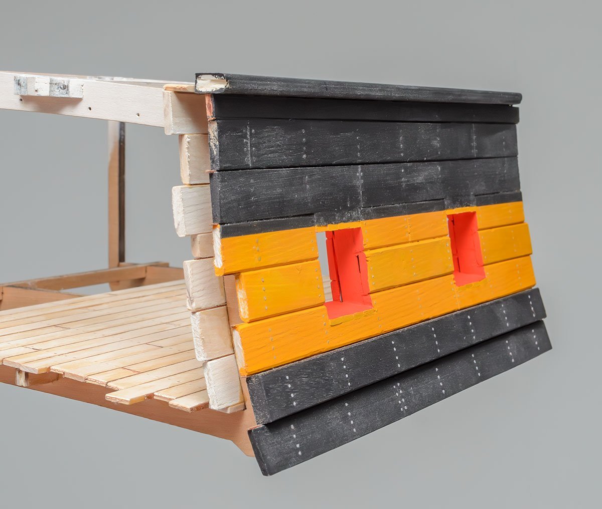
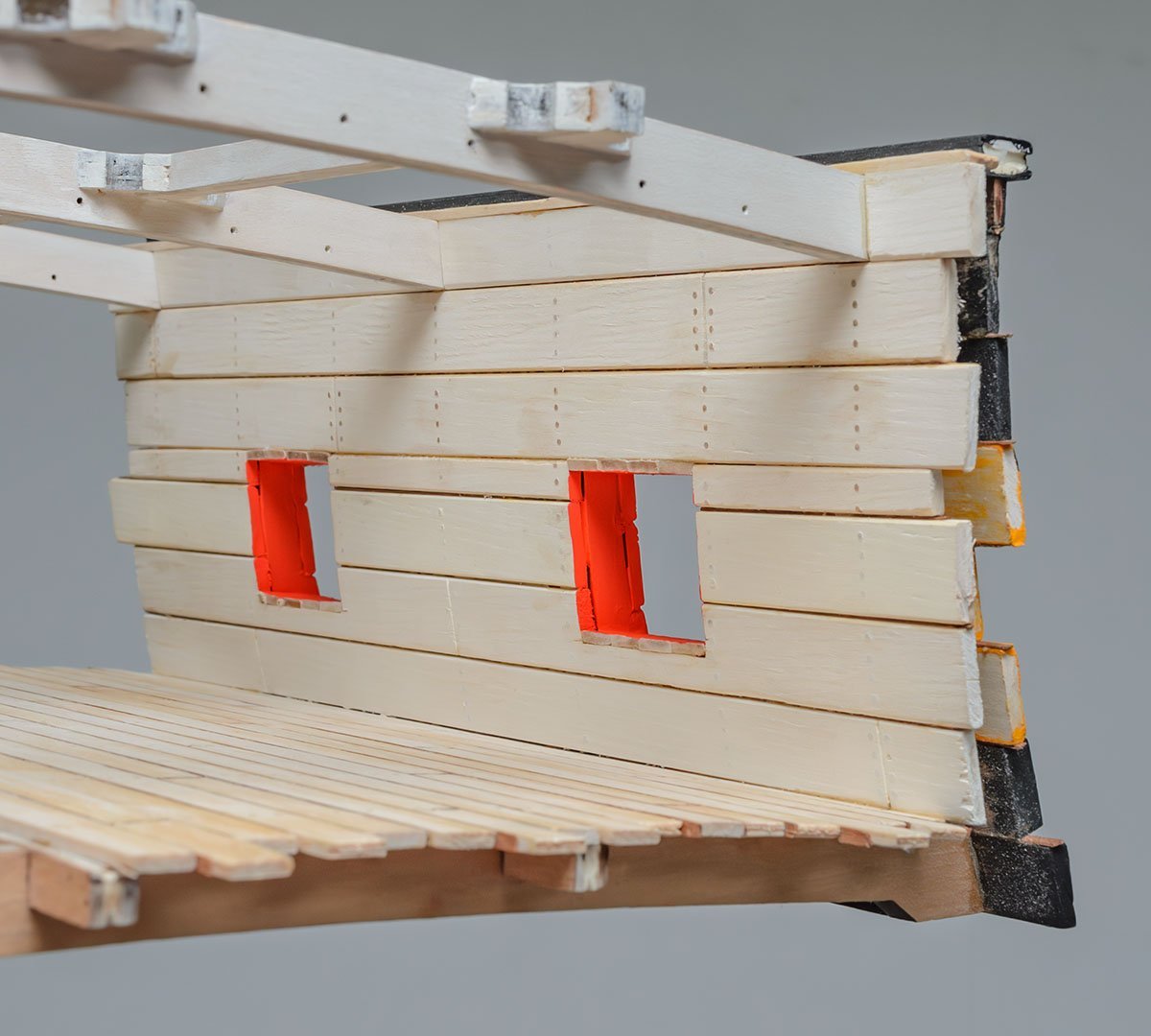
This classic kit has had various names for decades. You can find many build logs by searching the names. - Posto di combattimento - Battle station - Section Deck Between Gun Bays - Combat place

- 8 replies
-
- 5
-
-
- combat place
- Panart
- (and 2 more)