Richard44
-
Posts
429 -
Joined
-
Last visited
Content Type
Profiles
Forums
Gallery
Events
Everything posted by Richard44
-
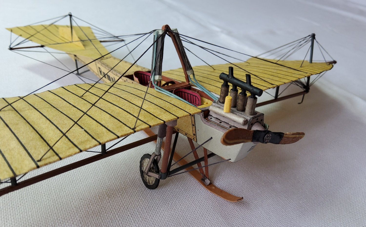
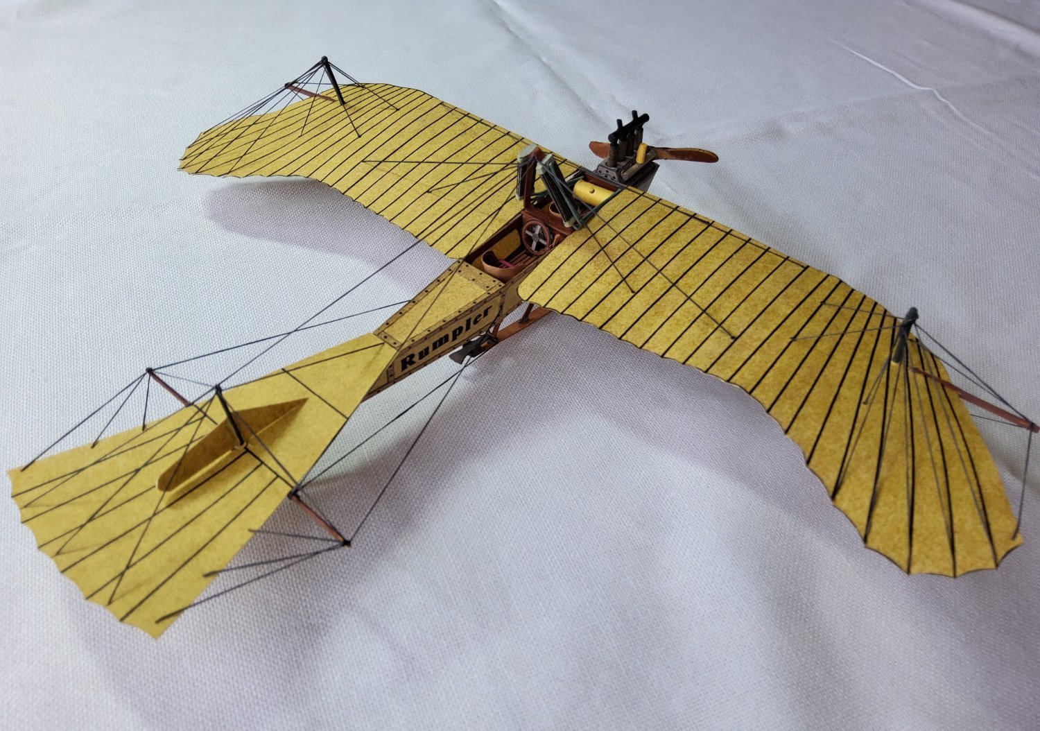
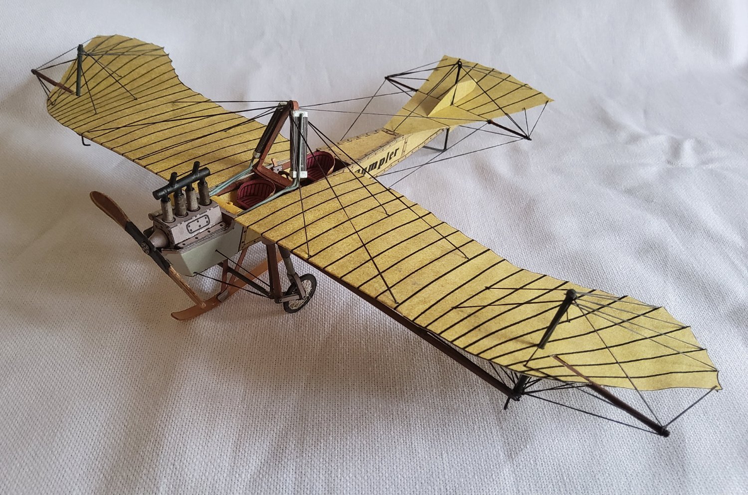
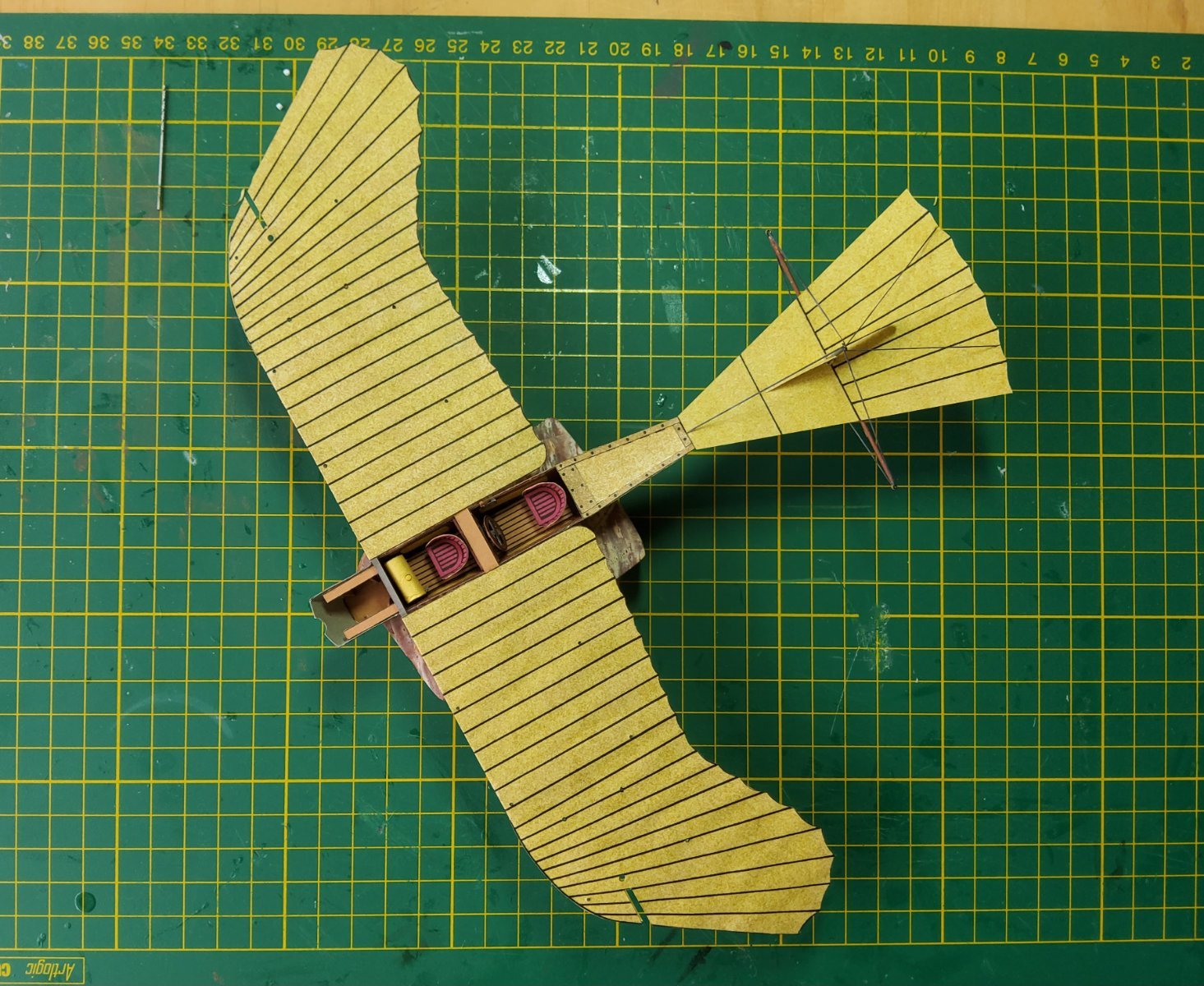
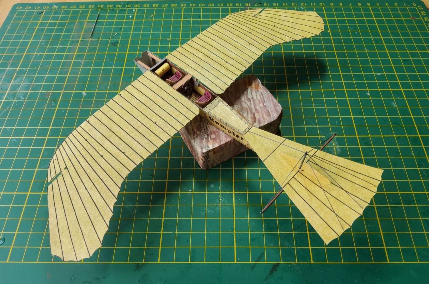
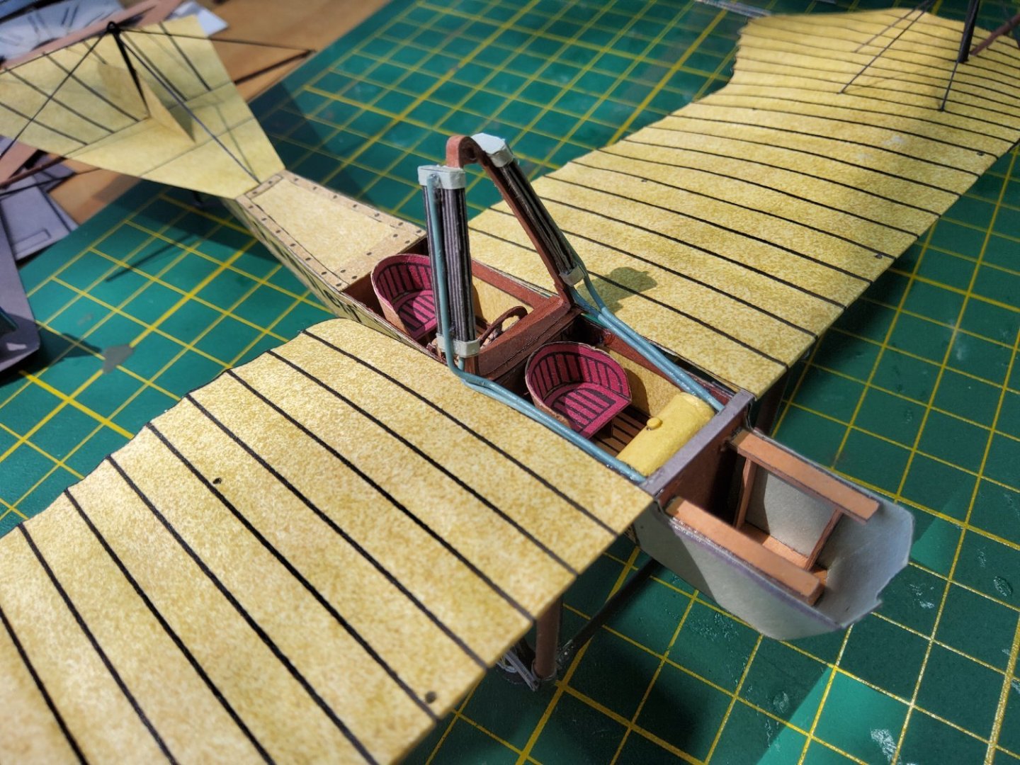
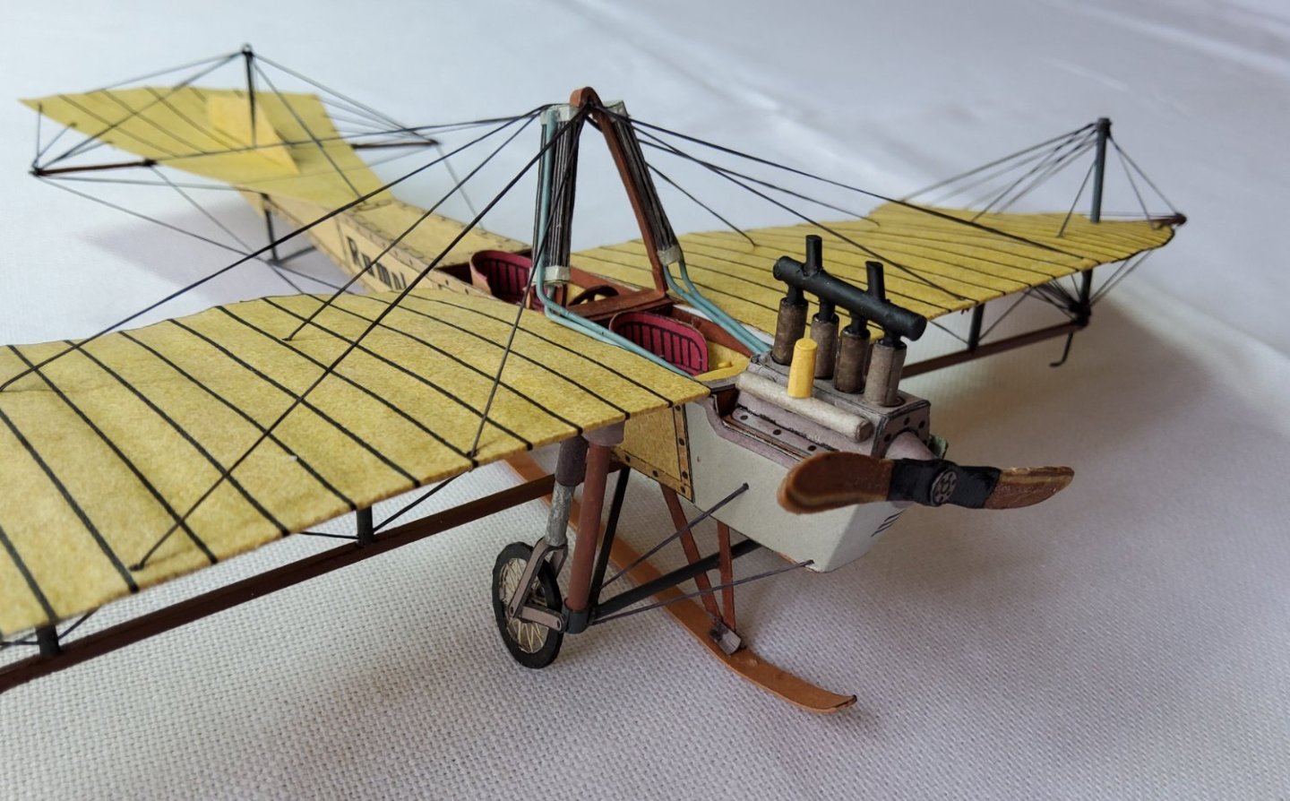
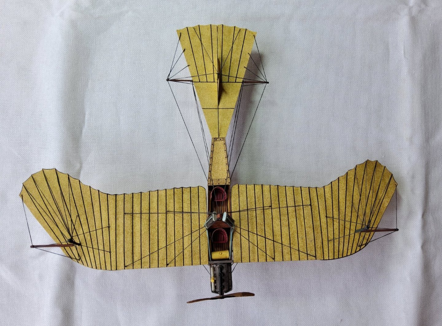
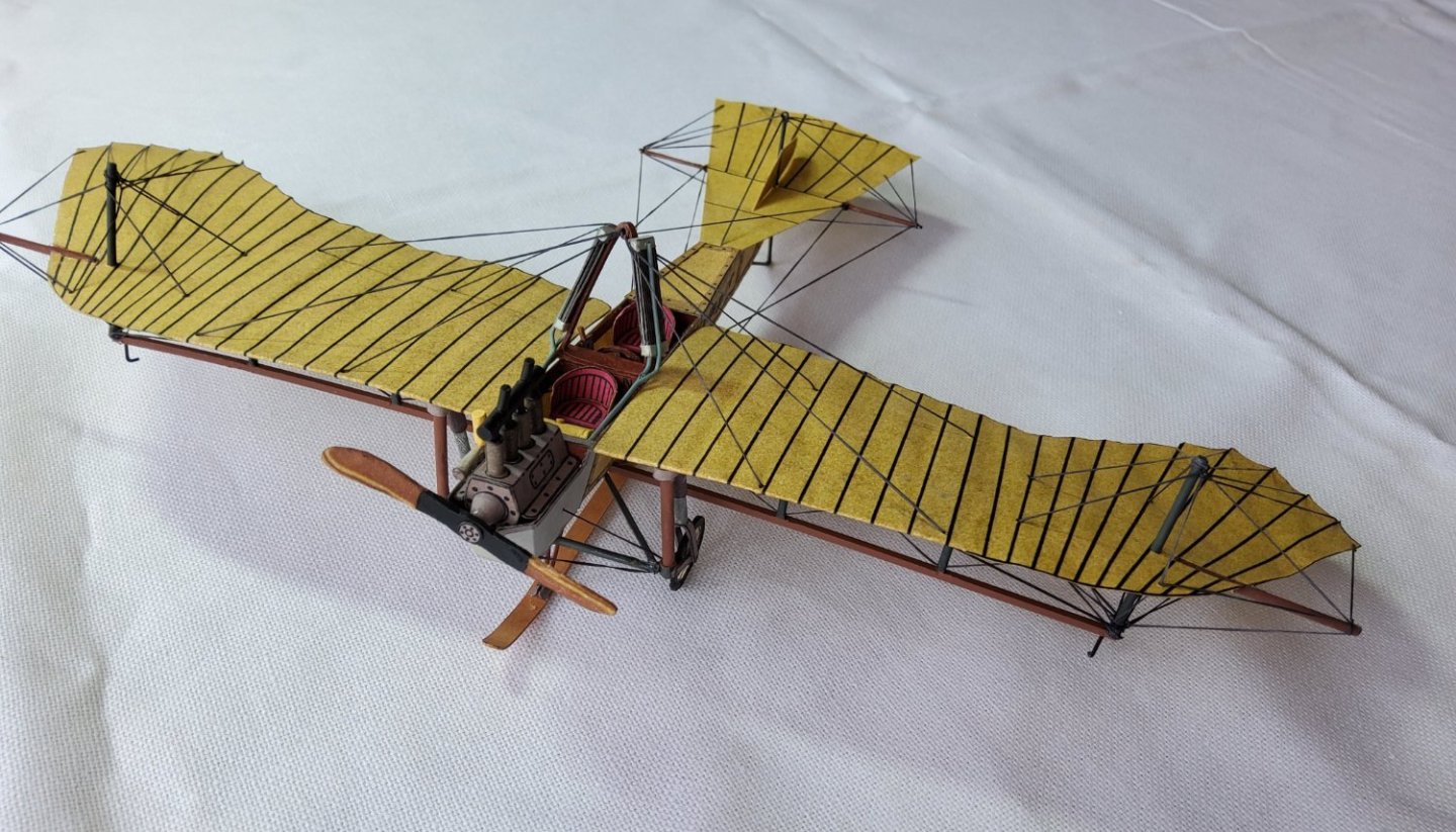
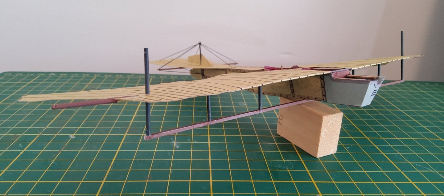
 The engine was liquid cooled, and the radiators (there were two) were mounted either side of a triangular pylon that was fastened to the fuselage between the two cockpits. (This pylon was also an important part of the rigging of the aircraft.) Other versions of the Taube, later or different manufacturers, had the radiators flat against each side of the fuselage immediately aft of the engine bay. The instructions give no hint as to how the coolant flowed between the engine and the radiators. Looking for photos on the net didn't help much, so I simply ran two styrene rods down from each radiator, along the top edge of the forward fuselage and into the engine bay. Quite possibly wrong, but at least the radiators don't look ridiculous. The rigging. As mentioned above, the diagram in the instructions didn't quite match the photo on the cover of the kit. A search of the internet showed many images of Taubes, mostly low-res. There were a few three views that allowed me to come up with an acceptable, to me anyway, rigging plan. There was still some uncertainty about some of the wires as start and end points could not be identified, so these were omitted. The main problem here was that I initially found no views of the underneath of the aircraft. After completing the rigging I did find two sites, with replicas, that showed the underside of the wings and fuselage. It was still not clear to me where some of the wires went so I left my completed rigging “as is”. (It looks as if one of the replicas, the one in the Deutsches Museum, was the basis for this model.) The engine was finally glued in place and the propeller added. I laminated the printed propeller with some lighter coloured card to give it a 3D appearance. So, here it is, the Rumpler Taube of 1911. Thanks to all who visited, reacted or left comments. Much appreciated. Cheers
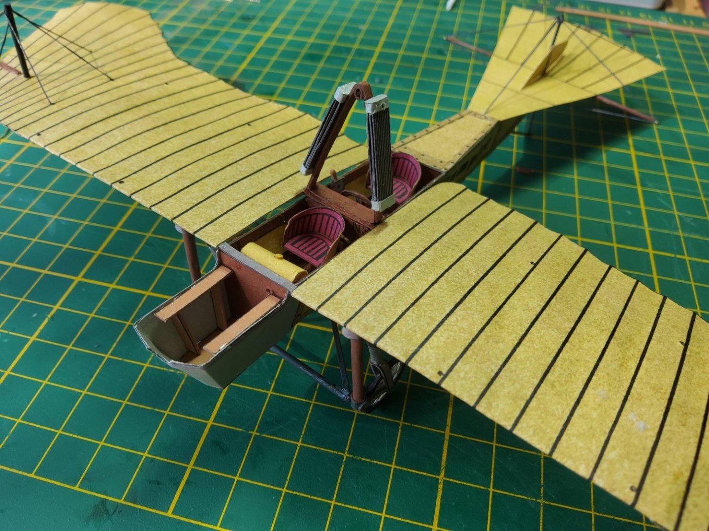


- 28 replies
-
- 13
-

-

-
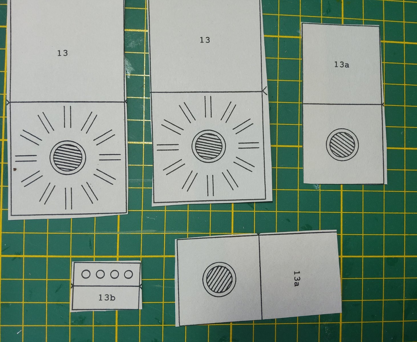
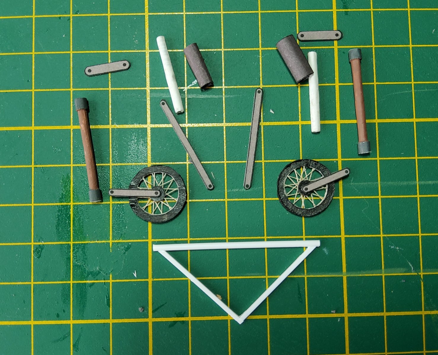
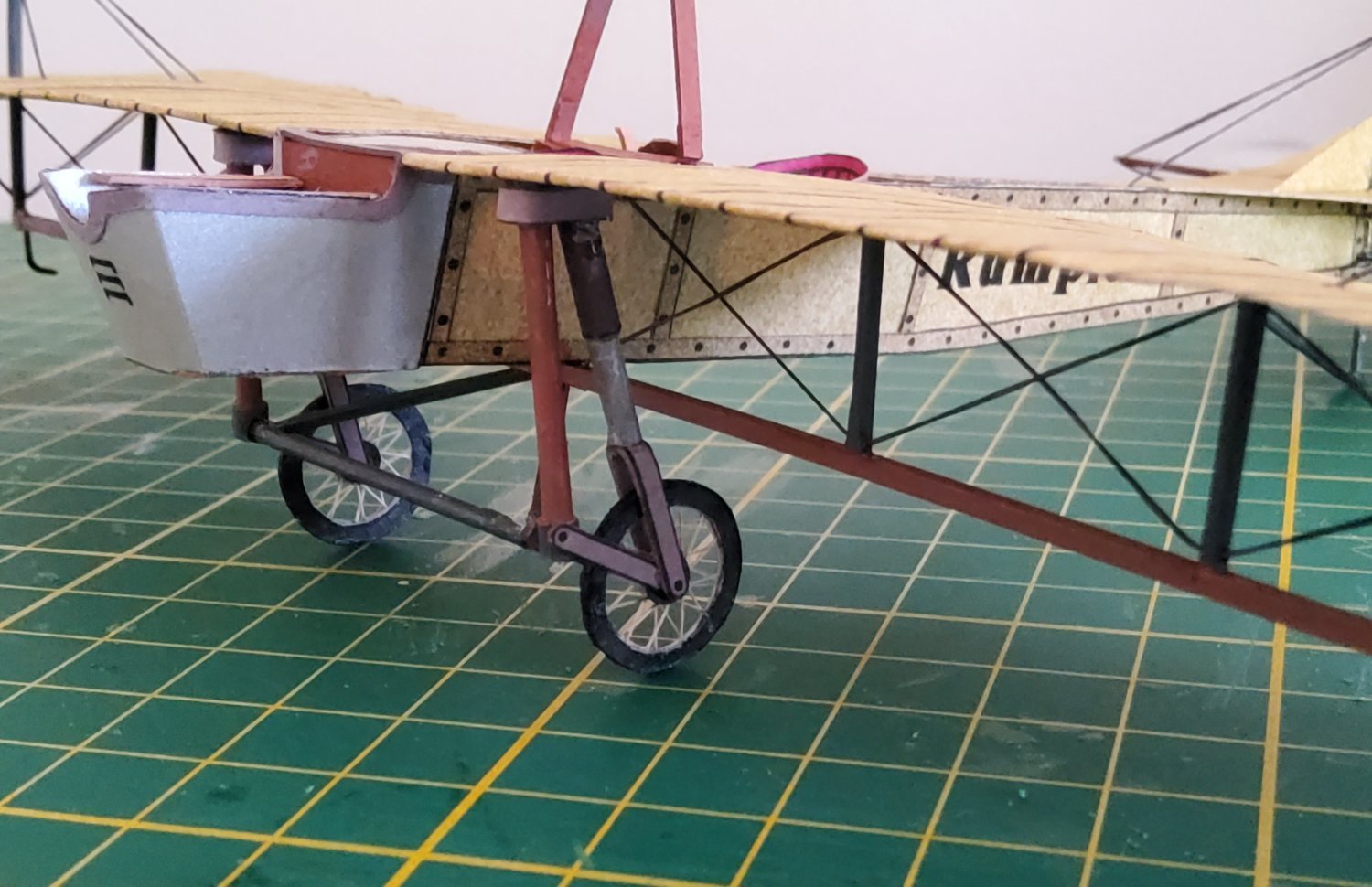
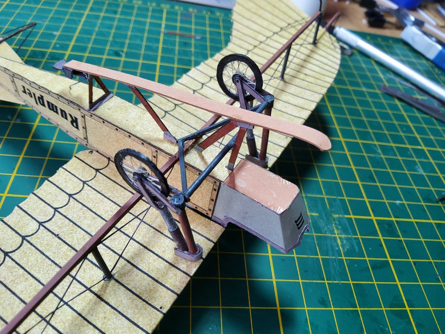
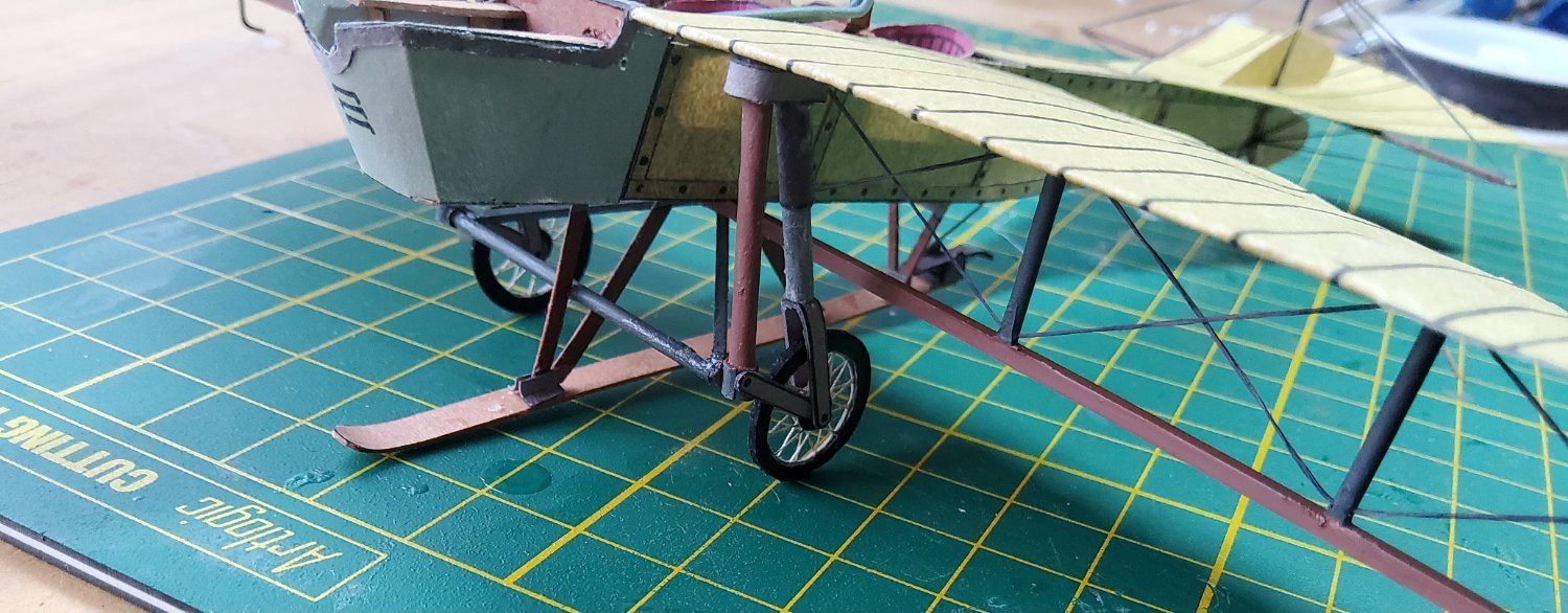
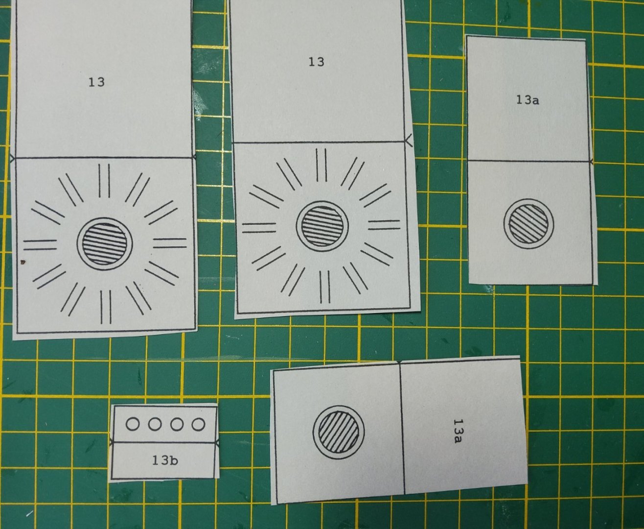
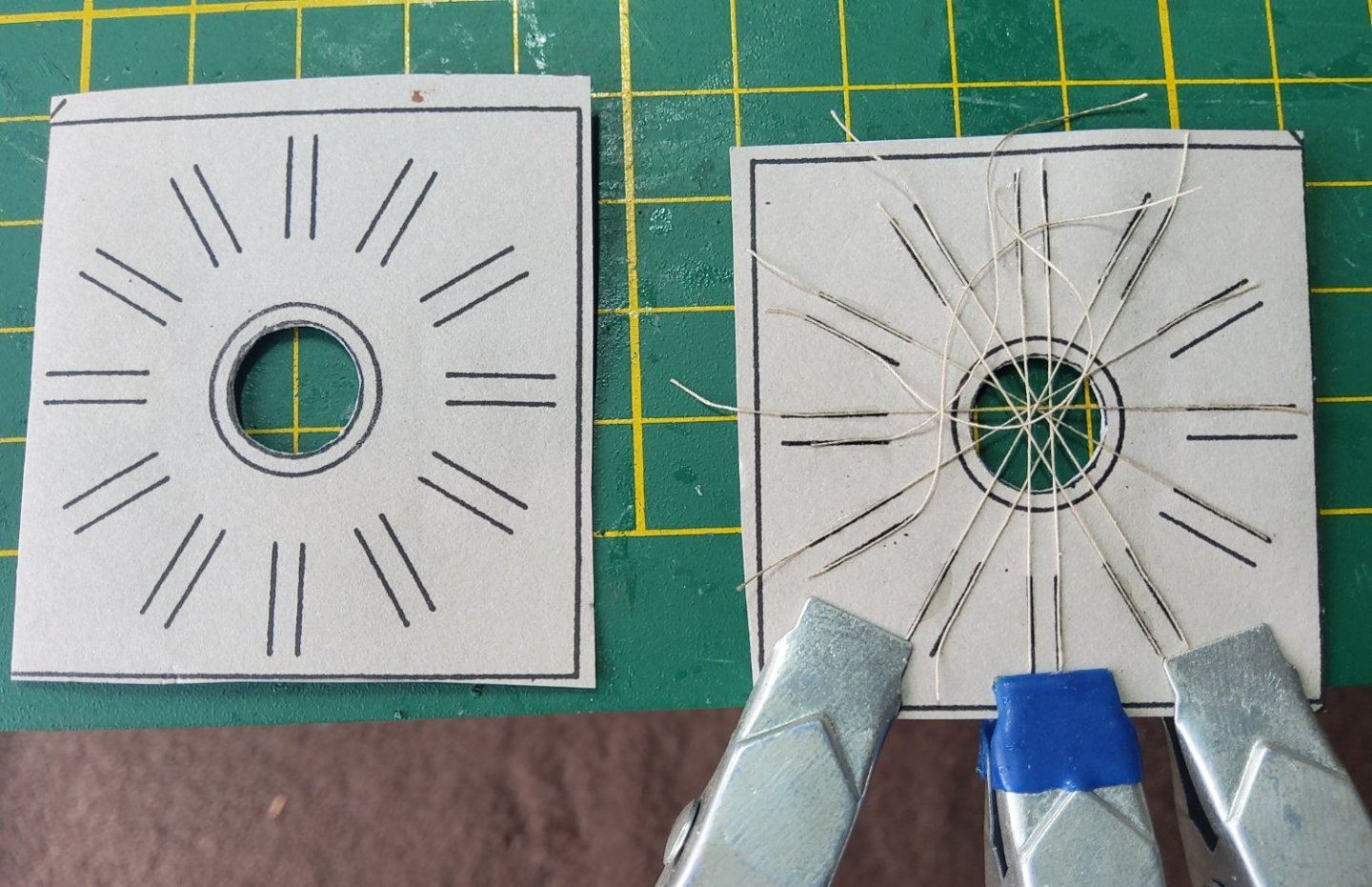
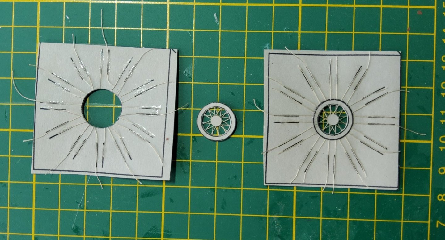
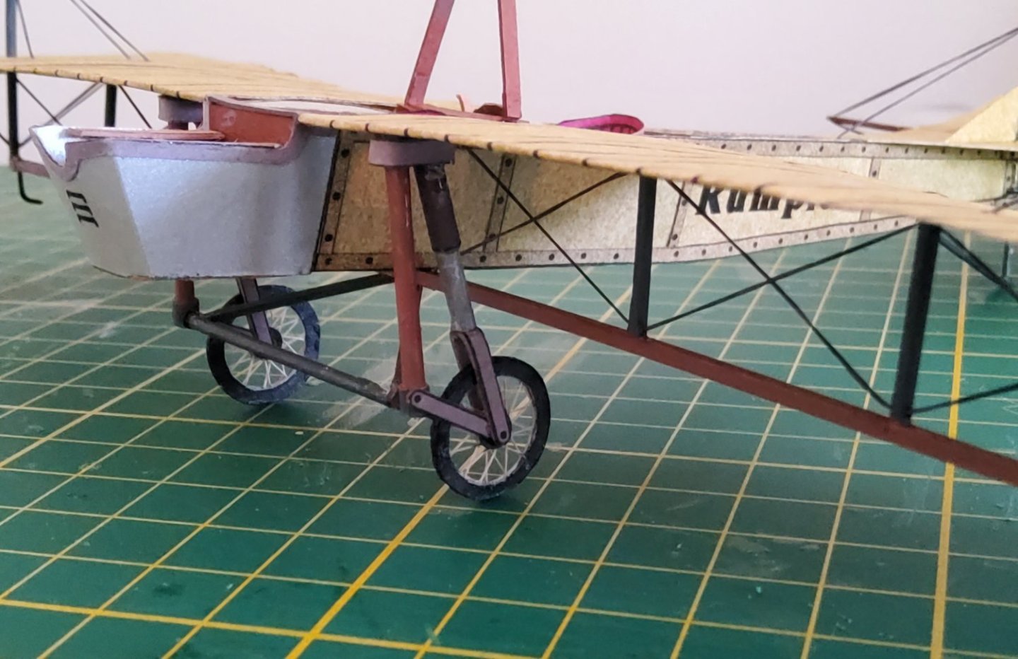
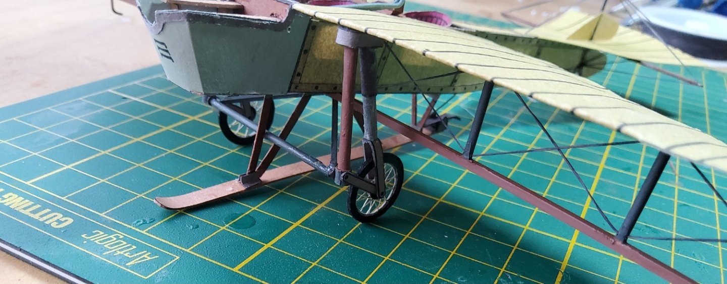
The undercarriage. First up, the wheels. These are spoked and the kit provides a neat way of building these. There are templates which include one wheel rim and separately, there is a second rim. The hatched central part of the wheel is cut out, the threads are glued onto the template in the indicated positions, then the second rim is glued on top and once completely dry, the spoked wheel is cut from the template. The various parts of the undercarriage, mostly card and some styrene. The undercarriage in place. The diagonal bracing of the bridge is apparent. Finally, a skid was mounted on struts along the bottom of the fuselage. On top of the skid at the rear, is the brake, designed to drop down and drag along the ground. Cheers


- 28 replies
-
- 10
-
-
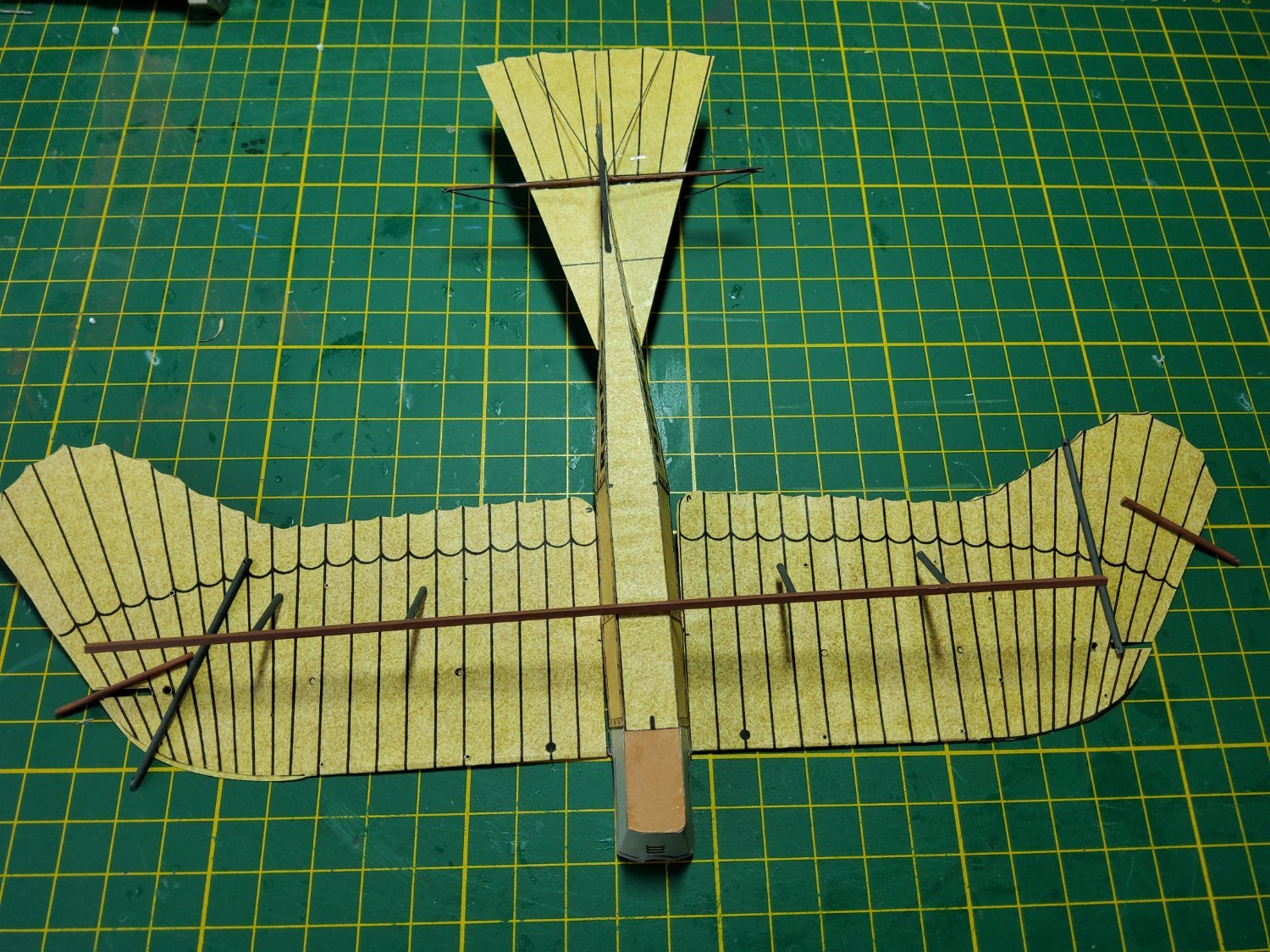
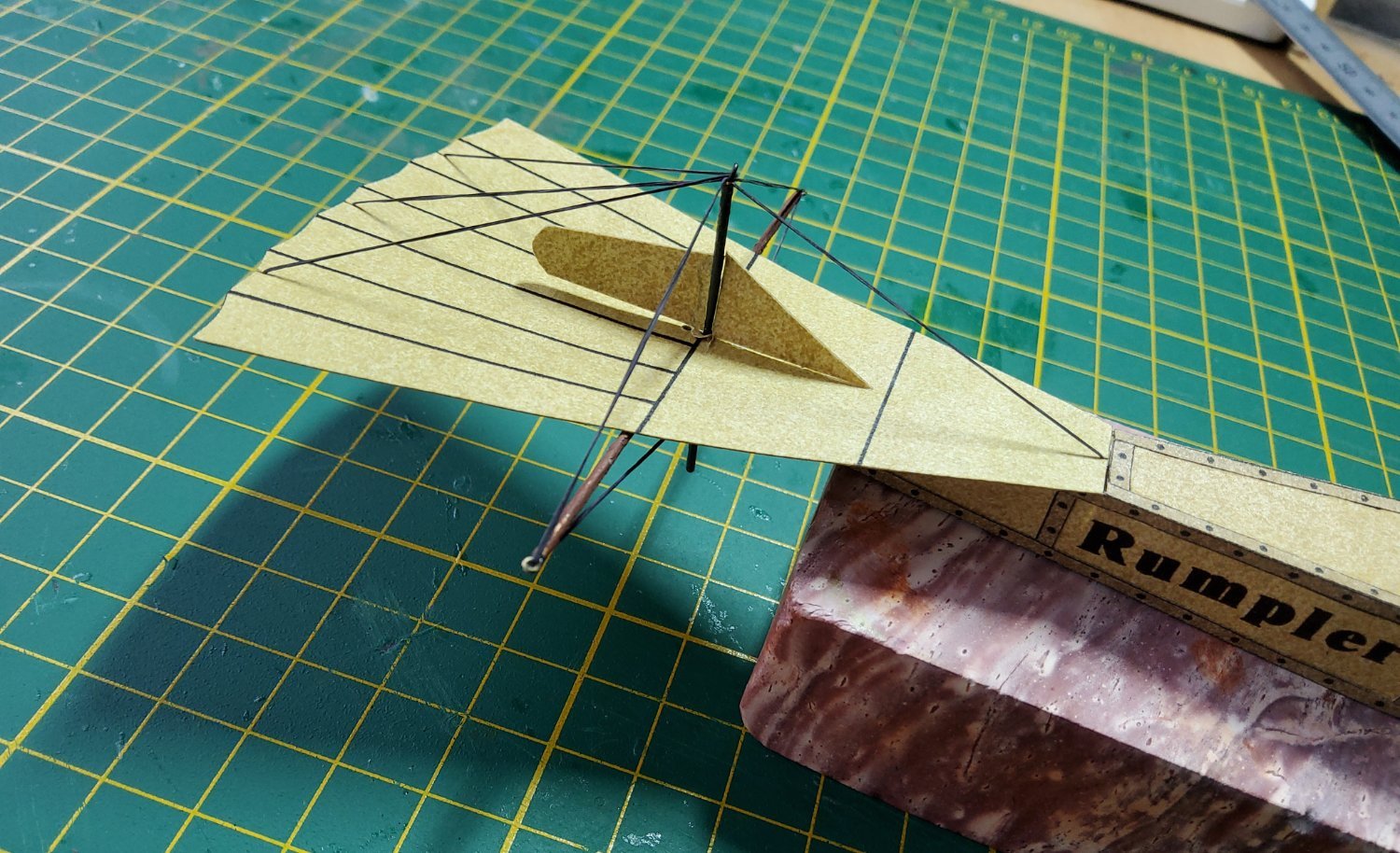
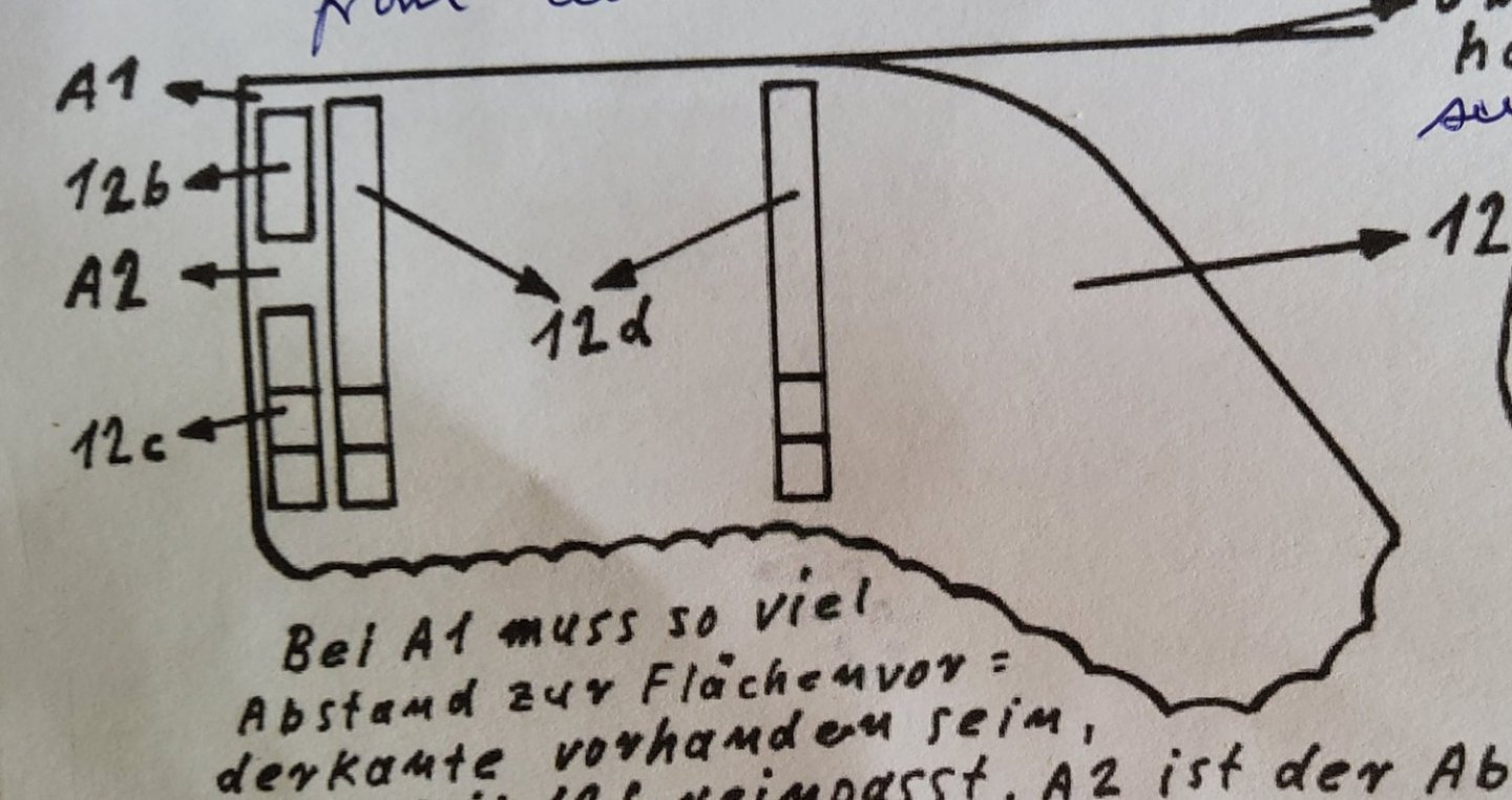
Thanks everyone for the visits, the likes and the comments. The wing was the next item. Very simple - skin, no spar and three ribs. I forgot to take a photo of the wing before folding and glueing the skin, but this image from the instructions shows the three ribs. These were laminated. Two short tabs that extend across the top of fuselage hold the wings - there is one at the leading edge and a larger one that slots through the gap in the first rib. Folding the skin and glueing it presented no problems, though the trailing edge needed some trimming as the upper and lower edges didn't always match. And this was very obvious given the scalloped trailing edge. Beneath the wing is what was called the “bridge”, basically a steel girder that gave support to the wing and all the rigging that was required, including that for the wing warping. I perhaps could have made it using the supplied printed parts, but again the small diameter tubes that were required defeated me. So styrene sections were used. The parts of the bridge ready for fixing in place. The four vertical pieces and the kingposts (all grey in the photo) were carefully drilled at each end to allow the diagonal bracing of the bridge to be done easily. There is also what seems to be an extension of the wing spar beyond the wing tip, and this was also drilled at the tip for the rigging. The basic bridge before rigging. Rigging was commenced but quickly stopped when I realised that the simple rigging diagram in the instructions didn't quite match the image on the cover of the kit. So I decided to do some internet searching before proceeding. In the meantime, I will tackle some other part of the build - the undercarriage. Cheers


- 28 replies
-
- 12
-
-
Hi Jeff, It's looking very good, even if there are some problems with the lengths of various parts. I did notice that you scratch built a replacement transom. It's too late now, but scanning the printed sheets into your computer is a really good way of having backup parts if required. Looking forward to the rest of your build. Cheers
- 63 replies
-
- 1
-
-
- card
- Revenue Cutter
- (and 2 more)
-
The engine in this version of the Taube was a Daimler/Mercedes design (E4F) of 70hp. Unlike the Wright engine, this one had a carburettor and a throttle. Other versions of the Taube (there were 14 or so different manufacturers) had 6 cylinder engines. Cheers Edit. Wikipedia lists 14 manufacturers but says the list is incomplete. Another site says "dozens" of manufacturers.
-
Yes, the sides are of very thin paper. Cheers
-
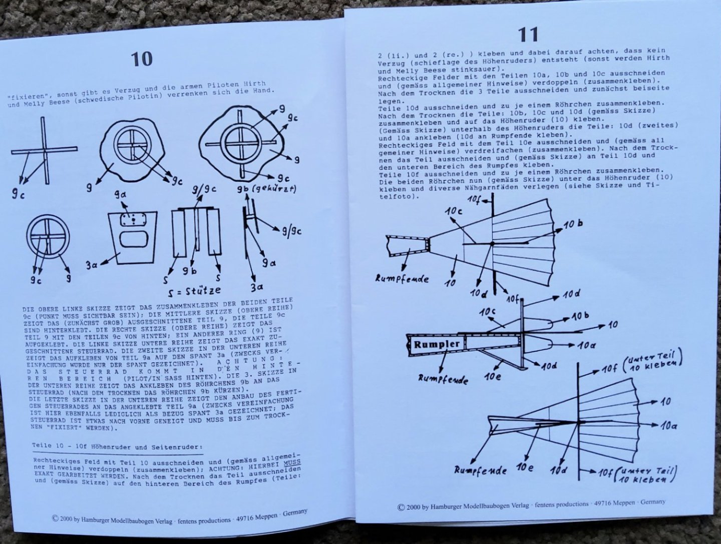
The tailplane is a simple card piece. There is no seperate elevator as the trailing edge was warped to provide pitch control. And if there was differential warping here, maybe some roll control as well. The vertical stabilizer has a small, fixed triangular fin and two parts to the actual rudder, above and below the tailplane. The rudder was the only control surface that was actually hinged. The rudderpost extends quite a way above and below the tailplane and rigging wires are to be attached to the top. There are also horizontal kingposts (not sure if this is the correct name) extending beyond the tailplane, and rigging is to be attached to each end. The rudderpost and the two kingposts should have been formed from rolled card as supplied, but trying to make these tubes between 2 and 3mm in diameter proved too much for my skills. I decided to use 2mm brass tube and glued small eyebolts into the ends to allow the rigging to be done easily. Rigging of the tail surfaces complete. There is a tailskid yet to be fastened to the bottom of the rudderpost. Cheers


- 28 replies
-
- 14
-
-
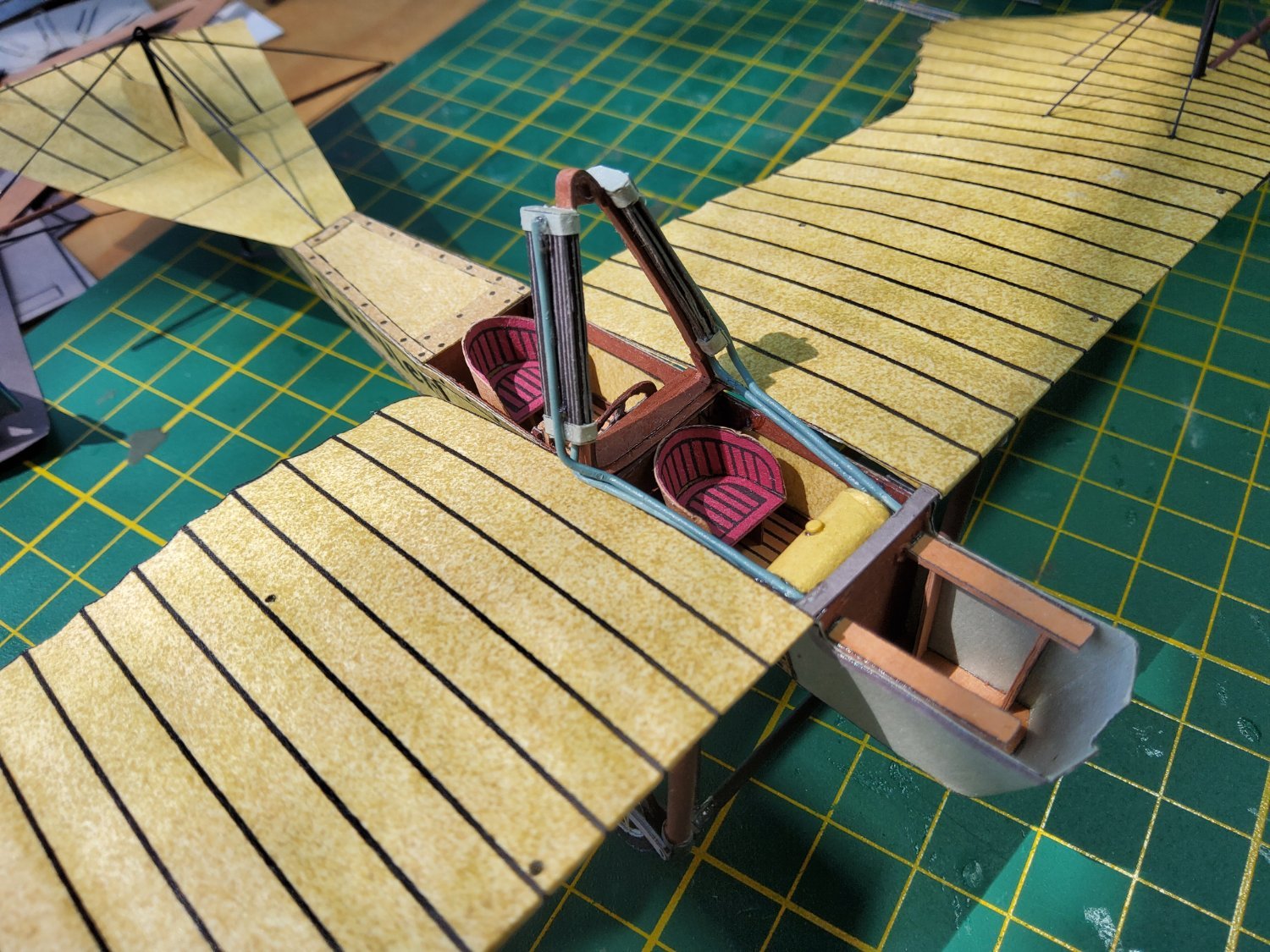
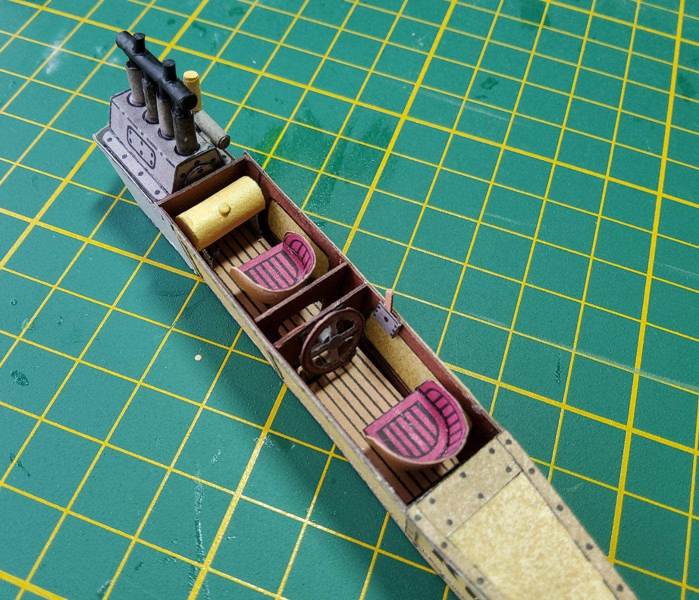
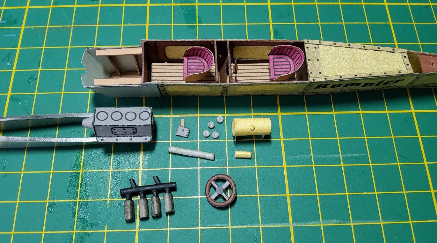
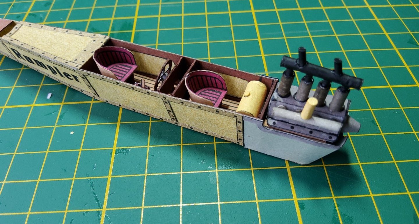
The fuselage now has rudder pedals in the rear cockpit and seats in both. The engine is partly assembled. I couldn't form the engine cylinders from the parts supplied, the card was a little too thick for me to make a neat cylinder, so I wrapped thin paper around a styrene core. The large yellow cylinder is the fuel tank, which will go into the front cockpit just above the legs of the occupier. The small yellow cylinder is the carburettor. The pilot's control wheel is ready to be fitted. The small grey square with the brown lever is the throttle. The engine completed and in place, though not glued, as I will remove it and fix it permanently later - it looks to be very vulnerable to a knock the way it sticks up. The other parts are in place. The engine looks very bare, no pipes or wires. There is nothing in the instructions and I couldn't find a suitable photo to show me what goes where. I'll maybe add some bits later. Cheers

- 28 replies
-
- 13
-
-
There are a few other models in this series - https://www.kartonmodellbau.de/kartonmodelle/?cat=24&manufacturer=422 I don't know that I have the nerve to tackle any of the others, except perhaps for the Bleriot.
-
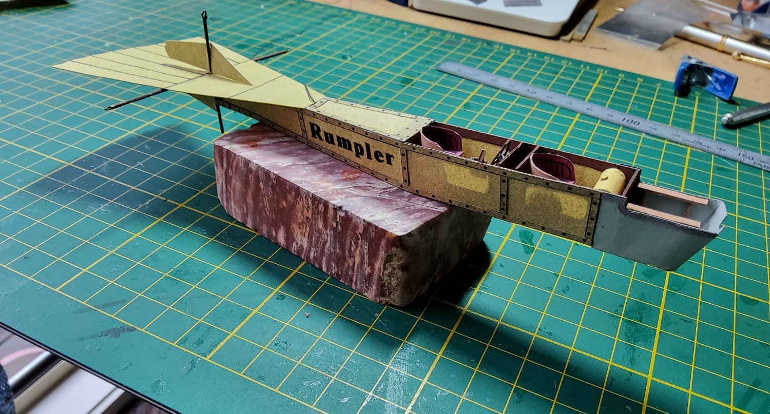
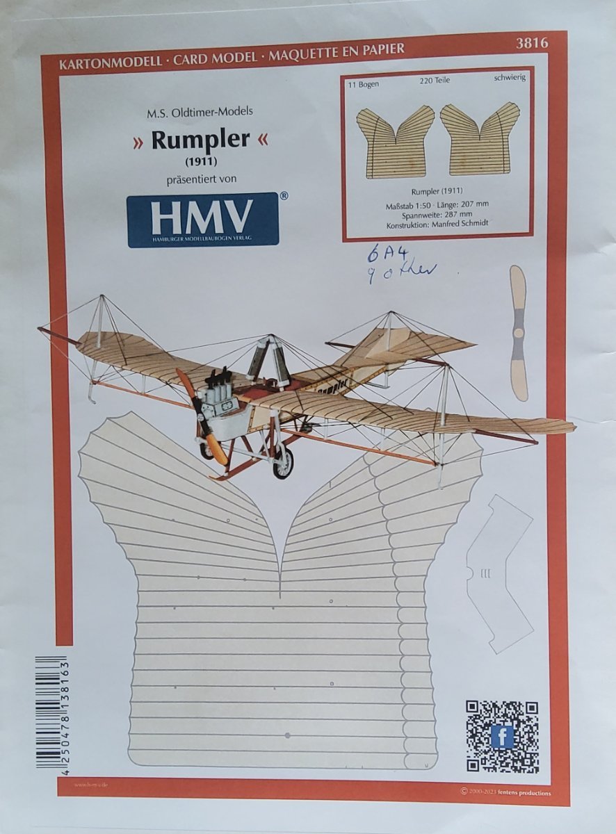
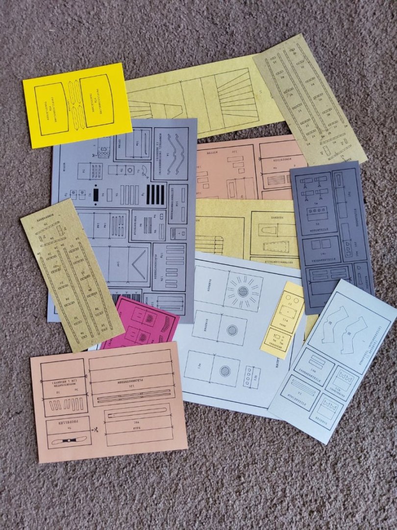
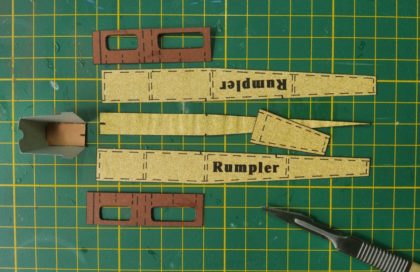
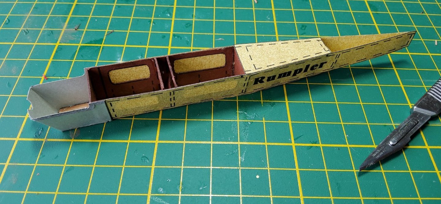
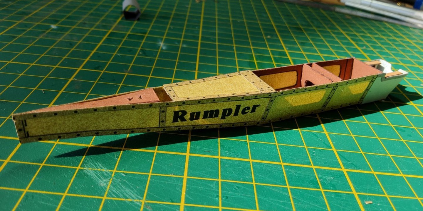
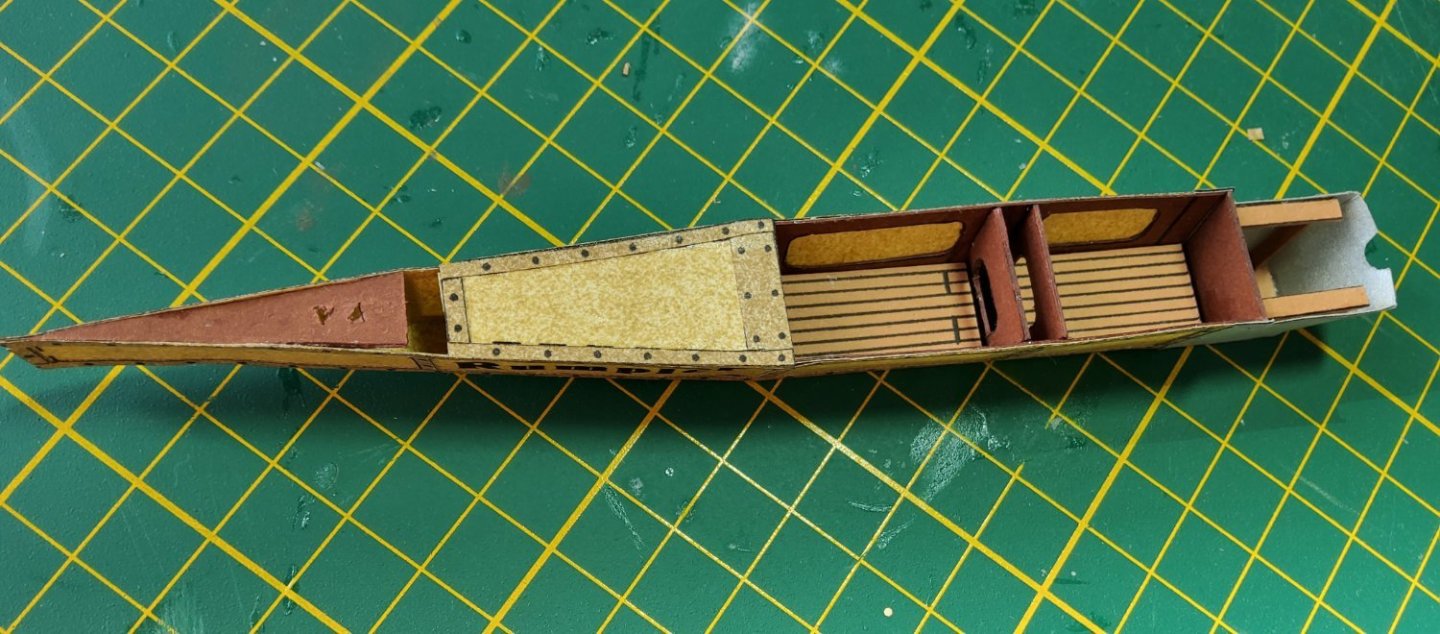
I happened to see this model while browsing a website and thought that it would be an interesting build. Firstly, some information about the actual aircraft. The following is an edited version of an article in Wikipedia. “The Taube was designed in 1909 by Igo Etrich of Austria-Hungary, and first flew in 1910. It was licensed for serial production by Lohner-Werke in Austria and by Edmund Rumpler in Germany, now called the Etrich-Rumpler-Taube. Rumpler soon changed the name to Rumpler-Taube, and stopped paying royalties to Etrich, who subsequently abandoned his patent. Despite its name (Taube means "dove"), the Taube's unique wing form was not modeled after a dove, but was copied from the seeds of Alsomitra macrocarpa, which may glide long distances from their parent tree. The wing has three spars and was braced by a cable-braced steel tube truss (called a "bridge") under each wing: at the outer ends the uprights of this structure were lengthened to rise above the upper wing surfaces, to form kingposts to carry bracing and warping wires for the enlarged wingtips. Later Taube-type aircraft from other manufacturers omitted the underwing "bridge" structure to reduce drag. Like many contemporary aircraft, especially monoplanes, the Taube used wing warping rather than ailerons for lateral (roll) control, and also warped the rear half of the stabilizer to function as the elevator. Only the vertical, twinned triangular rudder surfaces were usually hinged. The design provided for very stable flight, which made it extremely suitable for observation. The translucent wings made it difficult for ground observers to detect a Taube at an altitude above 400 meters. Poor rudder and lateral control made the Taube difficult and slow to turn. The aeroplane proved to be a very easy target for the faster and more agile Allied Scouts of the early part of World War I, and just six months into the war, the Taube had been removed from front line service to be used to train new pilots.” This model is a reissue of one that was released in, I think, 2000. It comprises 13 sheets of various sizes and thicknesses of coloured card and an A5 instruction manual of 24 pages (text and diagrams). The coloured card means that no edge colouring will be required. The instructions are in German and no English translation is available so Google translate is going to get a workout. There are no lasercut pieces, and it seems that there are no tabs or strip joiners. It appears that Google has done a more than reasonable job of translating the instructions, though there is some confusion in a few places. I feel that this confusion will be cleared up once I have cut the parts out and try to assemble them. However Google could not handle (read) the handwritten notes that are on many of the diagrams and these had to be entered manually into it. So, onto the build. The basic parts of the fuselage, with the engine bay already assembled. There are also four bulkheads shown in the following photo of the fuselage. This photo shows the fuselage with the engine bearers and floorboards in the two cockpits. I added a scrap piece in the rear to strengthen this area as it was extremely flimsy. Also printed strips replicating the structure of the fuselage have been added. Cheers

- 28 replies
-
- 18
-
-
Another "G'day" Dindsy, this time from Gosford. Enjoy MSW and good luck with Sirius. Cheers
-
Welcome to the club! 🙂🙂
-
Your boat's looking very good. I've pulled ropes until the slack is taken out then applied PVA to the rope to stiffen it. This usually works. CA will certainly stiffen the rope, but also hardens it and I've had thin lines break because of that. Cheers
-
Hi David, Can't help you on the actual lengths of planks for a boat like this. Back when I started the build, MSW didn't exist, and I knew almost nothing about full-size boat building practice. So I just built the hull basically straight from the box - I did make the comment at the beginning of this log that I would have done it differently had I known better. The info about plank lengths will certainly be available, but I have no reference books. Try a cross-post in "Building, framing....". Good luck with your build, I can guarantee it will at times try your patience! 😁 Cheers
-
No worries Mike, it's what I did!
-
Why not just mark the edges of the bulkheads where the cardinal marks are? File, pencil, whatever...Then you can have chipboard-to-chipboard and not worry about the craft glue. Cheers (looking forward to your build).
-
Hi Mike, If I were you, I wouldn't attempt to cut out that hatch. Simply lay some thin strips on top of the deck (ie. double plank it) and add the coaming around them. Keep at it Jonas, it does make up into a nice looking model if you survive the instructions etc. I remember just how much frustration I had at times when building that kit. Terrible instructions! Cheers
- 62 replies
-
- 2
-
-
- lancia armata
- panart
- (and 1 more)
-
Hi Jeff, So are the pieces simply butt-joined along the bulkhead? There's no joiner strip? How thick are the bulkheads? I'm watching your very nice build with interest as I'll be back making a card boat sometime in the near future. Cheers
- 63 replies
-
- 1
-
-
- card
- Revenue Cutter
- (and 2 more)
-
Hi, Another one of the Dutch subs, K XII, was wrecked on Fairlight beach, Sydney Harbour, in June 1949 after breaking its tow. It became a RAN vessel in 1943, but never saw service. It was moored alongside a pier at Manly wharf as a tourist attraction, but was being moved to a more sheltered site during a storm when it broke its tow. I well remember seeing it on the rocks - Fairlight was my local beach. Cheers https://www.flickr.com/photos/41311545@N05/5230854984
-
Thanks again everybody for just looking, liking or making comments. All very much appreciated. Cheers.
- 36 replies
-
- 2
-
-
- Shallop
- Pavel Nitikin
- (and 1 more)
-
Hi Chuck, Interesting video and yes, he does mention the yard. But says that he will leave it up to us to figure out how to work the sails! Cheers
-
Yes, it does have material that is printed for the sails. I forgot to mention that I wasn’t going to add the sails, though I may do so at some time.
- 36 replies
-
- 3
-
-
- Shallop
- Pavel Nitikin
- (and 1 more)
-
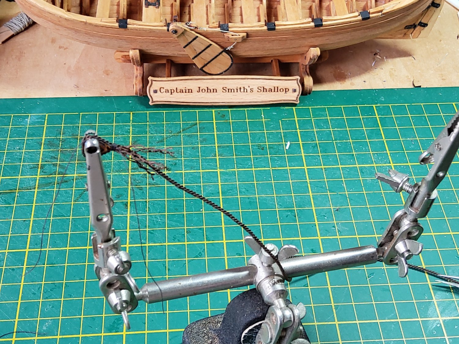
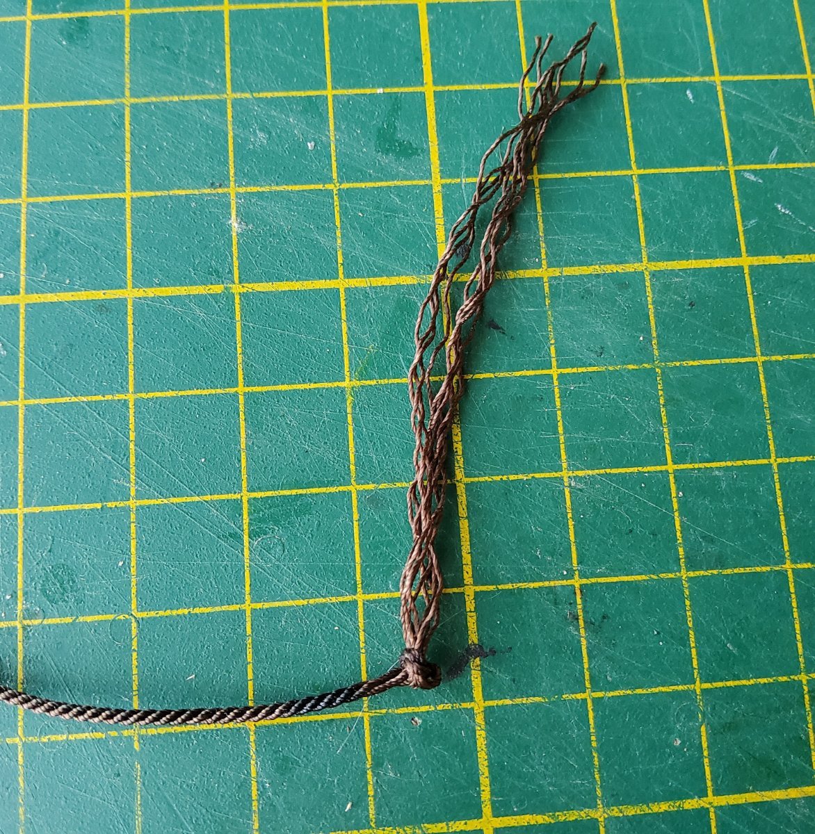
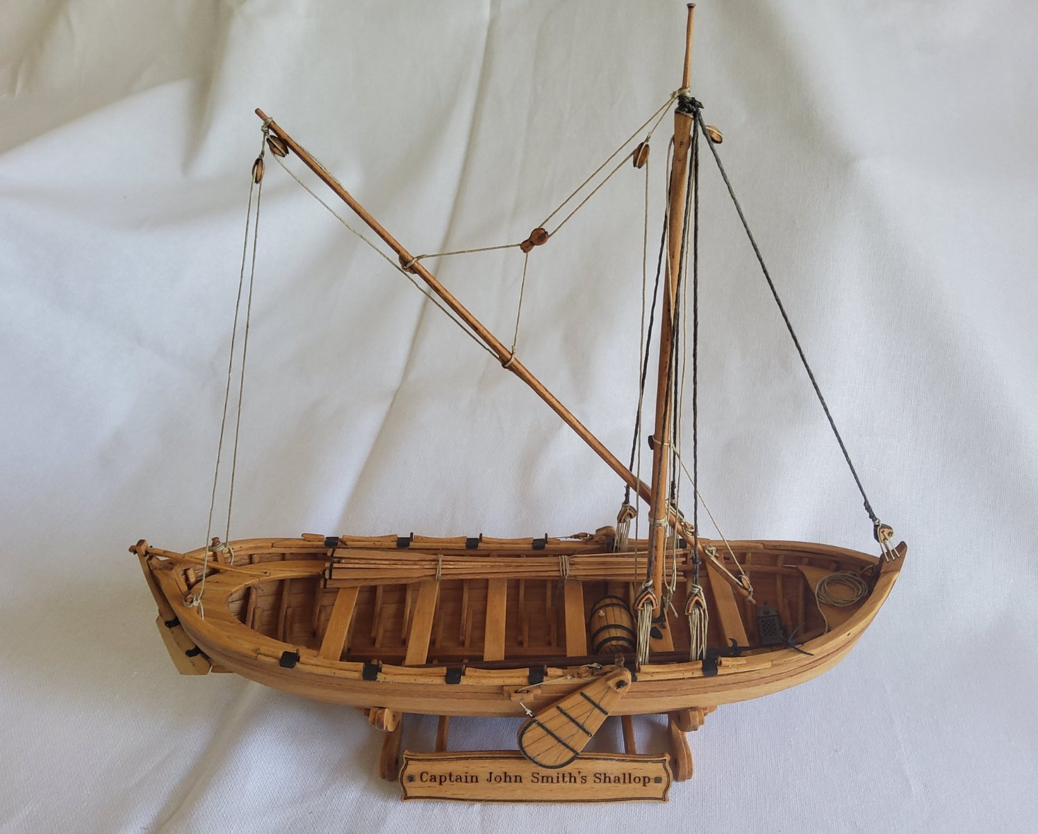
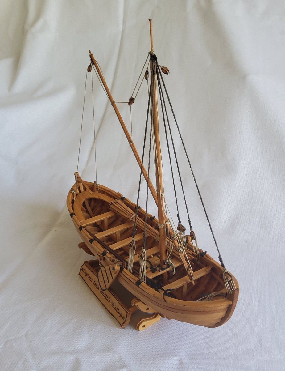
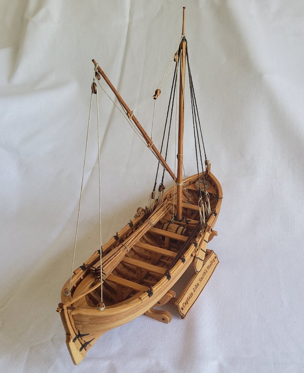
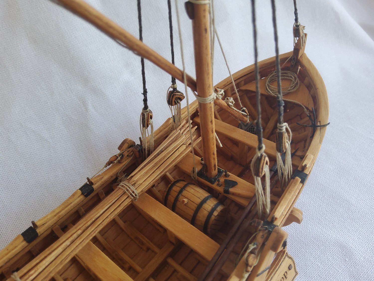
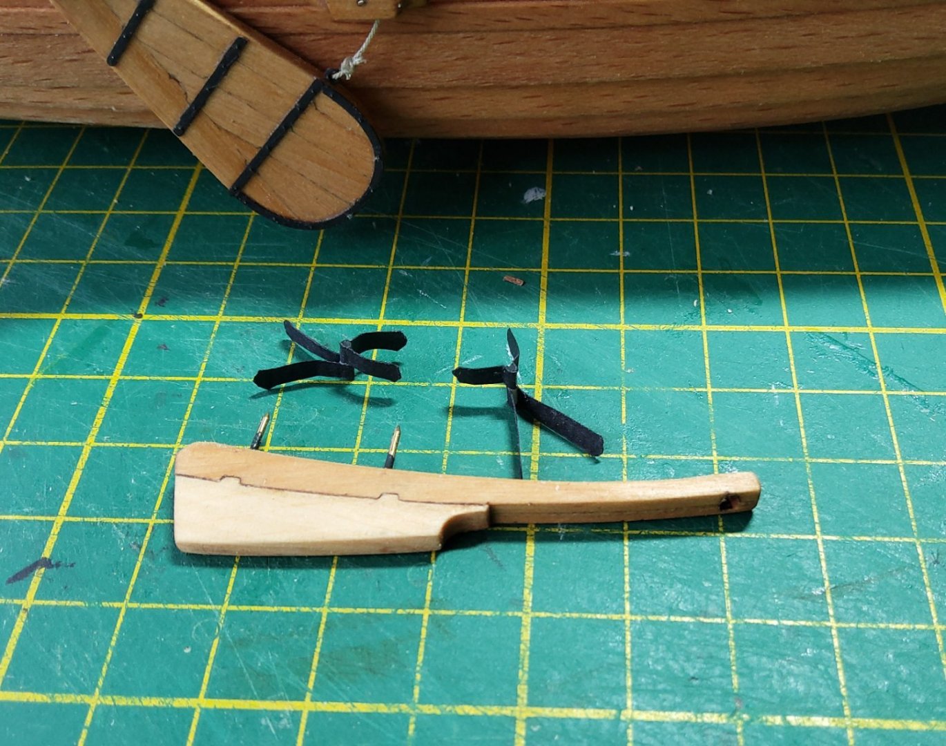
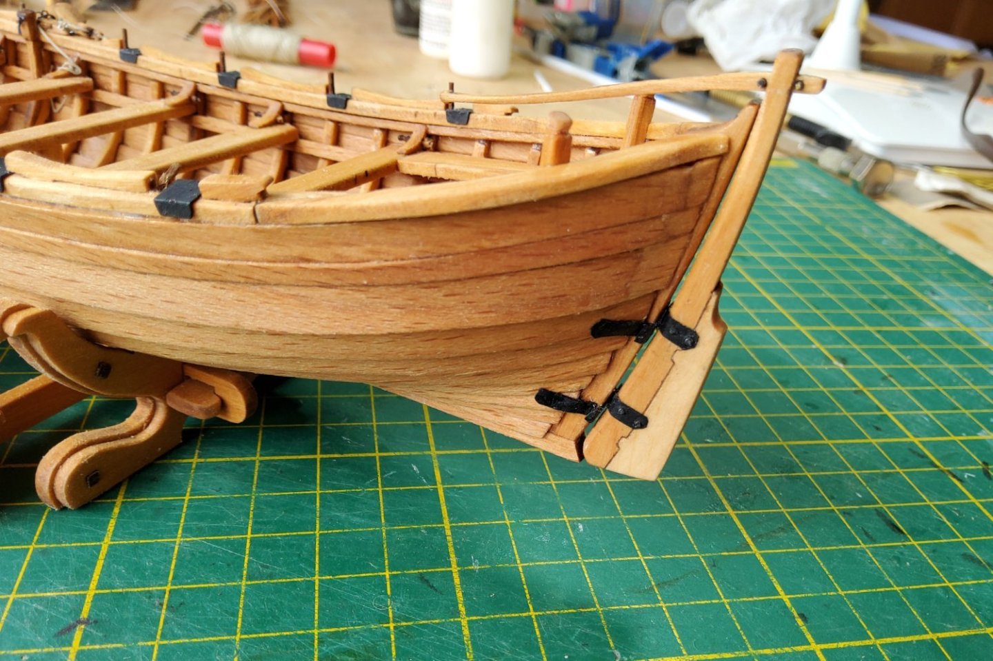
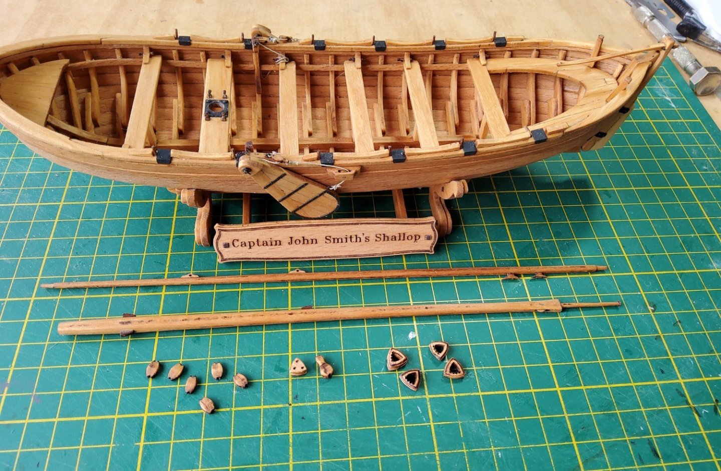
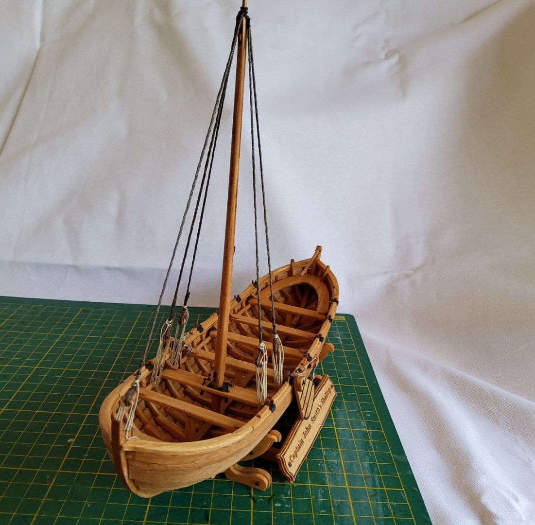
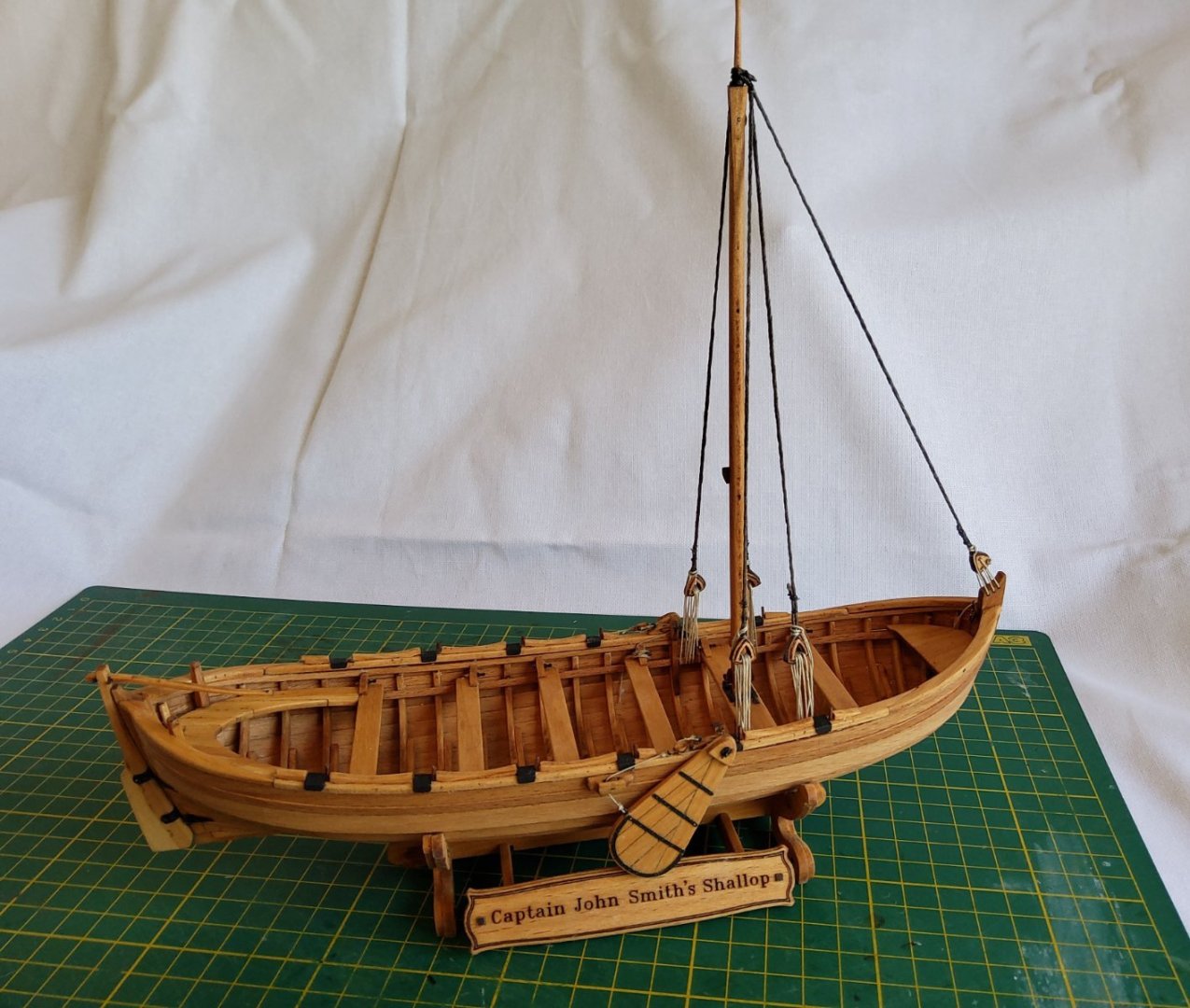
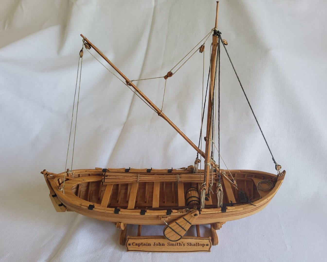
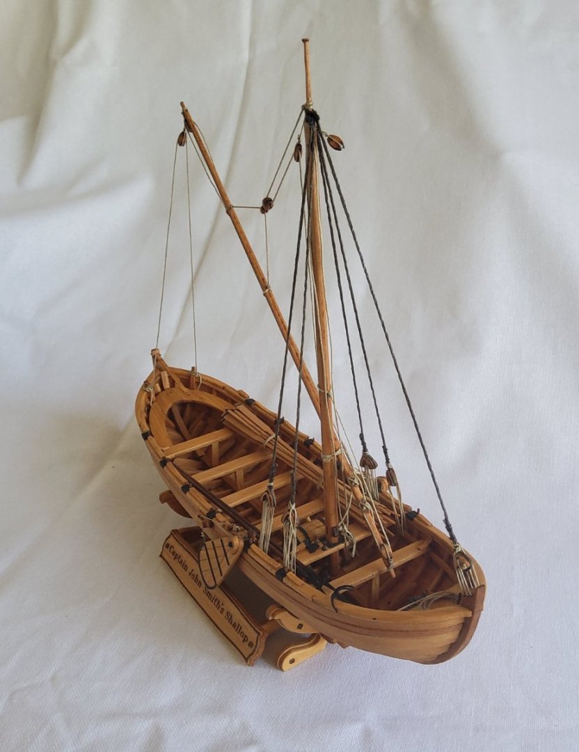
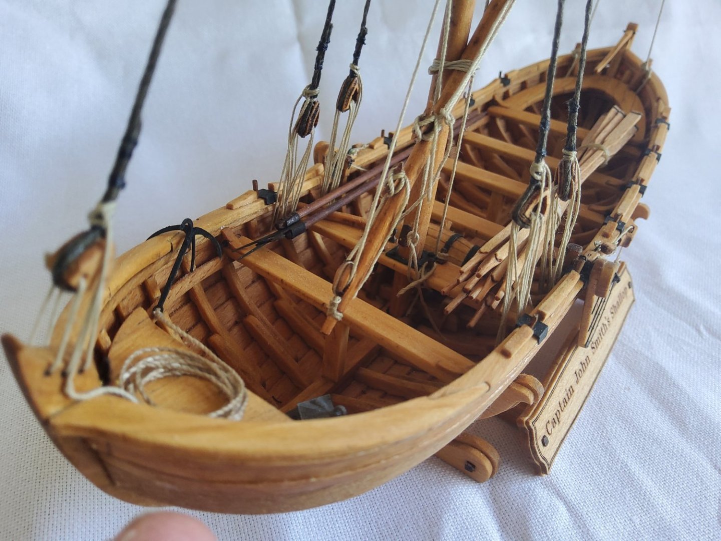
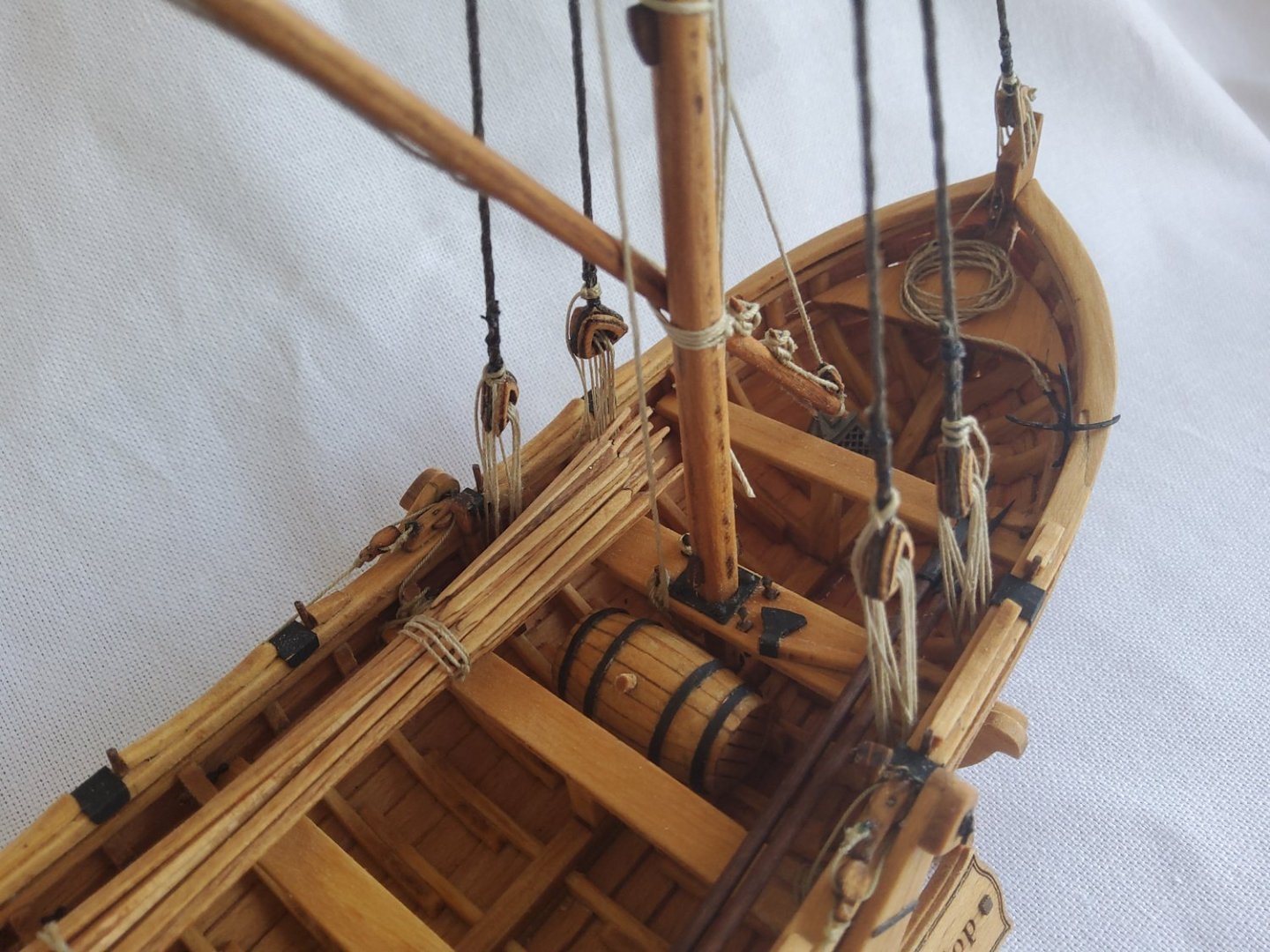
So, onto the final stretch. Firstly the rudder. The rudder itself is two pre-cut pieces, plus the pre-cut tiller. All needed cleaning up but otherwise no issues. There were brass PE straps provided but no actual pintles or gudgeons. I broke one of the straps while bending it into shape, so decided that straps made from black paper would serve and would be indistinguishable from the supplied brass straps at any reasonable viewing distance. Styrene rod was used for the pintles. I also decided that the rudder would need to be pinned to the sternpost as I didn’t think the paper straps would be sufficiently strong to hold it. When the assembled rudder etc was held up to the hull, it looked terrible. There was a large gap between the rudder and the sternpost. So I got rid of the styrene rod and just used the paper straps and the pinned rudder - certainly not prototypical but the end result is fine. And now for the rigging. One mast, one yard, two shrouds, one stay and some running rigging. Can't be too hard. The mast, yard and various blocks ready for installing. The mast and the yard came ready tapered and needed to be rounded and cleaned of char. A file and sandpaper took care of this. The mast was set in place ready for the shrouds. The manual and plans are quite detailed with every line identified but there is a considerable amount of careful perusal required as some things are a little obscure. The supplied cord for the shrouds was wrapped around one of the triangular blocks and seized with thin thread. The excess cord was cut and instant disaster 😬. The cord promptly unravelled.🥴 Not happy ☹️. I tried to seal the cord where I planned to cut it, but no glue that I have would stick to the polyester (I assume that’s what it is). I had some cord left over from another build, slightly undersized (1.0mm) compared to the supplied cord (1.2mm), but close enough. This cord was then used for the shrouds and the forestay. Again, cord I already had was used for the running rigging. No particular issues with this. However once I had most of the rigging done, the yard sort of flopped around with apparently nothing to hold it in place. I found one of Olha's videos that I hadn’t seen before and it showed her lashing the yard to the mast. A careful check of the plans showed on one of them, three thin lines where the yard crossed the mast - the lashing. The shallop is now finished. The extras in the boat, oars, water barrel etc have all been added. A fairly enjoyable build, some headaches on the way, but nothing to kill the build. Thanks to all who looked in, the likes and the comments. Cheers


- 36 replies
-
- 10
-
-
-
- Shallop
- Pavel Nitikin
- (and 1 more)
-
Hi Robert, You’re making good progress, but no, you won't catch me now 😁, I've finished, see post 🙂. As for the rigging of the yard, I've gone with the details on the plan sheets. I have no idea how the sails would be worked when the boat is tacked, maybe there's someone here who could tell us. Your illustration - have you colourised it? My plans are black and white. Cheers